EP3166166A1 - Film electrode composite, method for manufacturing film electrode composite, fuel cell, and method for manufacturing fuel cell - Google Patents
Film electrode composite, method for manufacturing film electrode composite, fuel cell, and method for manufacturing fuel cell Download PDFInfo
- Publication number
- EP3166166A1 EP3166166A1 EP15814963.3A EP15814963A EP3166166A1 EP 3166166 A1 EP3166166 A1 EP 3166166A1 EP 15814963 A EP15814963 A EP 15814963A EP 3166166 A1 EP3166166 A1 EP 3166166A1
- Authority
- EP
- European Patent Office
- Prior art keywords
- solid electrolyte
- electrolyte layer
- anode member
- layer
- electrode assembly
- Prior art date
- Legal status (The legal status is an assumption and is not a legal conclusion. Google has not performed a legal analysis and makes no representation as to the accuracy of the status listed.)
- Granted
Links
- 238000004519 manufacturing process Methods 0.000 title claims abstract description 36
- 238000000034 method Methods 0.000 title claims abstract description 32
- 239000000446 fuel Substances 0.000 title claims description 80
- 239000002131 composite material Substances 0.000 title description 4
- 239000007784 solid electrolyte Substances 0.000 claims abstract description 154
- 239000012528 membrane Substances 0.000 claims abstract description 64
- 239000010410 layer Substances 0.000 claims description 238
- 229910052751 metal Inorganic materials 0.000 claims description 58
- 239000002184 metal Substances 0.000 claims description 58
- 239000000463 material Substances 0.000 claims description 37
- PXHVJJICTQNCMI-UHFFFAOYSA-N Nickel Chemical compound [Ni] PXHVJJICTQNCMI-UHFFFAOYSA-N 0.000 claims description 26
- 229910045601 alloy Inorganic materials 0.000 claims description 10
- 239000000956 alloy Substances 0.000 claims description 10
- 229910052759 nickel Inorganic materials 0.000 claims description 8
- 230000003197 catalytic effect Effects 0.000 claims description 7
- 239000003054 catalyst Substances 0.000 claims description 5
- 239000011651 chromium Substances 0.000 claims description 4
- 239000004020 conductor Substances 0.000 claims description 4
- 239000002345 surface coating layer Substances 0.000 claims description 4
- 229910000859 α-Fe Inorganic materials 0.000 claims description 4
- 239000011796 hollow space material Substances 0.000 claims description 3
- 229910052804 chromium Inorganic materials 0.000 claims description 2
- 239000011247 coating layer Substances 0.000 claims description 2
- 229910001026 inconel Inorganic materials 0.000 claims description 2
- 230000015572 biosynthetic process Effects 0.000 description 20
- 238000010304 firing Methods 0.000 description 17
- 239000007789 gas Substances 0.000 description 16
- 238000007747 plating Methods 0.000 description 15
- 238000011056 performance test Methods 0.000 description 11
- 239000011148 porous material Substances 0.000 description 8
- 238000003825 pressing Methods 0.000 description 8
- 230000007797 corrosion Effects 0.000 description 7
- 238000005260 corrosion Methods 0.000 description 7
- 239000004033 plastic Substances 0.000 description 7
- 229910002811 Sm0.5Sr0.5CoO3 Inorganic materials 0.000 description 6
- 229910021526 gadolinium-doped ceria Inorganic materials 0.000 description 6
- 229910001233 yttria-stabilized zirconia Inorganic materials 0.000 description 6
- 230000003247 decreasing effect Effects 0.000 description 5
- 229910020630 Co Ni Inorganic materials 0.000 description 4
- 229910002440 Co–Ni Inorganic materials 0.000 description 4
- 229910018669 Mn—Co Inorganic materials 0.000 description 4
- BQCADISMDOOEFD-UHFFFAOYSA-N Silver Chemical compound [Ag] BQCADISMDOOEFD-UHFFFAOYSA-N 0.000 description 4
- QVGXLLKOCUKJST-UHFFFAOYSA-N atomic oxygen Chemical compound [O] QVGXLLKOCUKJST-UHFFFAOYSA-N 0.000 description 4
- 239000010406 cathode material Substances 0.000 description 4
- LNTHITQWFMADLM-UHFFFAOYSA-N gallic acid Chemical compound OC(=O)C1=CC(O)=C(O)C(O)=C1 LNTHITQWFMADLM-UHFFFAOYSA-N 0.000 description 4
- 229910052746 lanthanum Inorganic materials 0.000 description 4
- FZLIPJUXYLNCLC-UHFFFAOYSA-N lanthanum atom Chemical compound [La] FZLIPJUXYLNCLC-UHFFFAOYSA-N 0.000 description 4
- 239000001301 oxygen Substances 0.000 description 4
- 229910052760 oxygen Inorganic materials 0.000 description 4
- 229910052709 silver Inorganic materials 0.000 description 4
- 238000012360 testing method Methods 0.000 description 4
- UFHFLCQGNIYNRP-UHFFFAOYSA-N Hydrogen Chemical compound [H][H] UFHFLCQGNIYNRP-UHFFFAOYSA-N 0.000 description 3
- 230000006399 behavior Effects 0.000 description 3
- 239000000470 constituent Substances 0.000 description 3
- 239000001257 hydrogen Substances 0.000 description 3
- 229910052739 hydrogen Inorganic materials 0.000 description 3
- 239000000843 powder Substances 0.000 description 3
- 238000010248 power generation Methods 0.000 description 3
- 239000004332 silver Substances 0.000 description 3
- 239000007787 solid Substances 0.000 description 3
- QBYHSJRFOXINMH-UHFFFAOYSA-N [Co].[Sr].[La] Chemical compound [Co].[Sr].[La] QBYHSJRFOXINMH-UHFFFAOYSA-N 0.000 description 2
- 239000000853 adhesive Substances 0.000 description 2
- 230000001070 adhesive effect Effects 0.000 description 2
- 238000005275 alloying Methods 0.000 description 2
- 230000000712 assembly Effects 0.000 description 2
- 238000000429 assembly Methods 0.000 description 2
- MZZUATUOLXMCEY-UHFFFAOYSA-N cobalt manganese Chemical compound [Mn].[Co] MZZUATUOLXMCEY-UHFFFAOYSA-N 0.000 description 2
- ZGDWHDKHJKZZIQ-UHFFFAOYSA-N cobalt nickel Chemical compound [Co].[Ni].[Ni].[Ni] ZGDWHDKHJKZZIQ-UHFFFAOYSA-N 0.000 description 2
- 230000000694 effects Effects 0.000 description 2
- 239000000835 fiber Substances 0.000 description 2
- 239000010416 ion conductor Substances 0.000 description 2
- 238000009940 knitting Methods 0.000 description 2
- 239000000203 mixture Substances 0.000 description 2
- 239000011347 resin Substances 0.000 description 2
- 229920005989 resin Polymers 0.000 description 2
- 229910021522 yttrium-doped barium zirconate Inorganic materials 0.000 description 2
- 229920000049 Carbon (fiber) Polymers 0.000 description 1
- 241000968352 Scandia <hydrozoan> Species 0.000 description 1
- 229910052788 barium Inorganic materials 0.000 description 1
- DSAJWYNOEDNPEQ-UHFFFAOYSA-N barium atom Chemical compound [Ba] DSAJWYNOEDNPEQ-UHFFFAOYSA-N 0.000 description 1
- 239000004917 carbon fiber Substances 0.000 description 1
- 238000000748 compression moulding Methods 0.000 description 1
- 239000012141 concentrate Substances 0.000 description 1
- 238000007796 conventional method Methods 0.000 description 1
- 230000008034 disappearance Effects 0.000 description 1
- 230000005489 elastic deformation Effects 0.000 description 1
- 239000003792 electrolyte Substances 0.000 description 1
- 238000005516 engineering process Methods 0.000 description 1
- 239000002737 fuel gas Substances 0.000 description 1
- 238000010438 heat treatment Methods 0.000 description 1
- XMHIUKTWLZUKEX-UHFFFAOYSA-N hexacosanoic acid Chemical compound CCCCCCCCCCCCCCCCCCCCCCCCCC(O)=O XMHIUKTWLZUKEX-UHFFFAOYSA-N 0.000 description 1
- -1 hydrogen ions Chemical class 0.000 description 1
- 229910052742 iron Inorganic materials 0.000 description 1
- 239000011572 manganese Substances 0.000 description 1
- 238000012986 modification Methods 0.000 description 1
- 230000004048 modification Effects 0.000 description 1
- 239000007800 oxidant agent Substances 0.000 description 1
- HJGMWXTVGKLUAQ-UHFFFAOYSA-N oxygen(2-);scandium(3+) Chemical compound [O-2].[O-2].[O-2].[Sc+3].[Sc+3] HJGMWXTVGKLUAQ-UHFFFAOYSA-N 0.000 description 1
- 239000002245 particle Substances 0.000 description 1
- 230000002093 peripheral effect Effects 0.000 description 1
- 229910052697 platinum Inorganic materials 0.000 description 1
- 238000007650 screen-printing Methods 0.000 description 1
- 238000007789 sealing Methods 0.000 description 1
- 229910002076 stabilized zirconia Inorganic materials 0.000 description 1
- IGPAMRAHTMKVDN-UHFFFAOYSA-N strontium dioxido(dioxo)manganese lanthanum(3+) Chemical compound [Sr+2].[La+3].[O-][Mn]([O-])(=O)=O IGPAMRAHTMKVDN-UHFFFAOYSA-N 0.000 description 1
Images


Classifications
-
- H—ELECTRICITY
- H01—ELECTRIC ELEMENTS
- H01M—PROCESSES OR MEANS, e.g. BATTERIES, FOR THE DIRECT CONVERSION OF CHEMICAL ENERGY INTO ELECTRICAL ENERGY
- H01M8/00—Fuel cells; Manufacture thereof
- H01M8/10—Fuel cells with solid electrolytes
- H01M8/12—Fuel cells with solid electrolytes operating at high temperature, e.g. with stabilised ZrO2 electrolyte
- H01M8/1213—Fuel cells with solid electrolytes operating at high temperature, e.g. with stabilised ZrO2 electrolyte characterised by the electrode/electrolyte combination or the supporting material
-
- H—ELECTRICITY
- H01—ELECTRIC ELEMENTS
- H01M—PROCESSES OR MEANS, e.g. BATTERIES, FOR THE DIRECT CONVERSION OF CHEMICAL ENERGY INTO ELECTRICAL ENERGY
- H01M4/00—Electrodes
- H01M4/86—Inert electrodes with catalytic activity, e.g. for fuel cells
-
- H—ELECTRICITY
- H01—ELECTRIC ELEMENTS
- H01M—PROCESSES OR MEANS, e.g. BATTERIES, FOR THE DIRECT CONVERSION OF CHEMICAL ENERGY INTO ELECTRICAL ENERGY
- H01M4/00—Electrodes
- H01M4/86—Inert electrodes with catalytic activity, e.g. for fuel cells
- H01M4/8605—Porous electrodes
-
- H—ELECTRICITY
- H01—ELECTRIC ELEMENTS
- H01M—PROCESSES OR MEANS, e.g. BATTERIES, FOR THE DIRECT CONVERSION OF CHEMICAL ENERGY INTO ELECTRICAL ENERGY
- H01M4/00—Electrodes
- H01M4/86—Inert electrodes with catalytic activity, e.g. for fuel cells
- H01M4/8605—Porous electrodes
- H01M4/8621—Porous electrodes containing only metallic or ceramic material, e.g. made by sintering or sputtering
-
- H—ELECTRICITY
- H01—ELECTRIC ELEMENTS
- H01M—PROCESSES OR MEANS, e.g. BATTERIES, FOR THE DIRECT CONVERSION OF CHEMICAL ENERGY INTO ELECTRICAL ENERGY
- H01M4/00—Electrodes
- H01M4/86—Inert electrodes with catalytic activity, e.g. for fuel cells
- H01M4/8647—Inert electrodes with catalytic activity, e.g. for fuel cells consisting of more than one material, e.g. consisting of composites
- H01M4/8657—Inert electrodes with catalytic activity, e.g. for fuel cells consisting of more than one material, e.g. consisting of composites layered
-
- H—ELECTRICITY
- H01—ELECTRIC ELEMENTS
- H01M—PROCESSES OR MEANS, e.g. BATTERIES, FOR THE DIRECT CONVERSION OF CHEMICAL ENERGY INTO ELECTRICAL ENERGY
- H01M4/00—Electrodes
- H01M4/86—Inert electrodes with catalytic activity, e.g. for fuel cells
- H01M4/88—Processes of manufacture
-
- H—ELECTRICITY
- H01—ELECTRIC ELEMENTS
- H01M—PROCESSES OR MEANS, e.g. BATTERIES, FOR THE DIRECT CONVERSION OF CHEMICAL ENERGY INTO ELECTRICAL ENERGY
- H01M4/00—Electrodes
- H01M4/86—Inert electrodes with catalytic activity, e.g. for fuel cells
- H01M4/90—Selection of catalytic material
- H01M4/9041—Metals or alloys
- H01M4/905—Metals or alloys specially used in fuel cell operating at high temperature, e.g. SOFC
-
- H—ELECTRICITY
- H01—ELECTRIC ELEMENTS
- H01M—PROCESSES OR MEANS, e.g. BATTERIES, FOR THE DIRECT CONVERSION OF CHEMICAL ENERGY INTO ELECTRICAL ENERGY
- H01M4/00—Electrodes
- H01M4/86—Inert electrodes with catalytic activity, e.g. for fuel cells
- H01M4/90—Selection of catalytic material
- H01M4/9075—Catalytic material supported on carriers, e.g. powder carriers
-
- H—ELECTRICITY
- H01—ELECTRIC ELEMENTS
- H01M—PROCESSES OR MEANS, e.g. BATTERIES, FOR THE DIRECT CONVERSION OF CHEMICAL ENERGY INTO ELECTRICAL ENERGY
- H01M8/00—Fuel cells; Manufacture thereof
- H01M8/02—Details
-
- H—ELECTRICITY
- H01—ELECTRIC ELEMENTS
- H01M—PROCESSES OR MEANS, e.g. BATTERIES, FOR THE DIRECT CONVERSION OF CHEMICAL ENERGY INTO ELECTRICAL ENERGY
- H01M8/00—Fuel cells; Manufacture thereof
- H01M8/02—Details
- H01M8/0202—Collectors; Separators, e.g. bipolar separators; Interconnectors
- H01M8/023—Porous and characterised by the material
- H01M8/0232—Metals or alloys
-
- H—ELECTRICITY
- H01—ELECTRIC ELEMENTS
- H01M—PROCESSES OR MEANS, e.g. BATTERIES, FOR THE DIRECT CONVERSION OF CHEMICAL ENERGY INTO ELECTRICAL ENERGY
- H01M8/00—Fuel cells; Manufacture thereof
- H01M8/02—Details
- H01M8/0202—Collectors; Separators, e.g. bipolar separators; Interconnectors
- H01M8/023—Porous and characterised by the material
- H01M8/0241—Composites
- H01M8/0245—Composites in the form of layered or coated products
-
- H—ELECTRICITY
- H01—ELECTRIC ELEMENTS
- H01M—PROCESSES OR MEANS, e.g. BATTERIES, FOR THE DIRECT CONVERSION OF CHEMICAL ENERGY INTO ELECTRICAL ENERGY
- H01M8/00—Fuel cells; Manufacture thereof
- H01M8/02—Details
- H01M8/0297—Arrangements for joining electrodes, reservoir layers, heat exchange units or bipolar separators to each other
-
- H—ELECTRICITY
- H01—ELECTRIC ELEMENTS
- H01M—PROCESSES OR MEANS, e.g. BATTERIES, FOR THE DIRECT CONVERSION OF CHEMICAL ENERGY INTO ELECTRICAL ENERGY
- H01M8/00—Fuel cells; Manufacture thereof
- H01M8/10—Fuel cells with solid electrolytes
- H01M8/12—Fuel cells with solid electrolytes operating at high temperature, e.g. with stabilised ZrO2 electrolyte
-
- H—ELECTRICITY
- H01—ELECTRIC ELEMENTS
- H01M—PROCESSES OR MEANS, e.g. BATTERIES, FOR THE DIRECT CONVERSION OF CHEMICAL ENERGY INTO ELECTRICAL ENERGY
- H01M8/00—Fuel cells; Manufacture thereof
- H01M8/24—Grouping of fuel cells, e.g. stacking of fuel cells
- H01M8/241—Grouping of fuel cells, e.g. stacking of fuel cells with solid or matrix-supported electrolytes
- H01M8/2425—High-temperature cells with solid electrolytes
- H01M8/2432—Grouping of unit cells of planar configuration
-
- H—ELECTRICITY
- H01—ELECTRIC ELEMENTS
- H01M—PROCESSES OR MEANS, e.g. BATTERIES, FOR THE DIRECT CONVERSION OF CHEMICAL ENERGY INTO ELECTRICAL ENERGY
- H01M4/00—Electrodes
- H01M4/86—Inert electrodes with catalytic activity, e.g. for fuel cells
- H01M2004/8678—Inert electrodes with catalytic activity, e.g. for fuel cells characterised by the polarity
- H01M2004/8684—Negative electrodes
-
- H—ELECTRICITY
- H01—ELECTRIC ELEMENTS
- H01M—PROCESSES OR MEANS, e.g. BATTERIES, FOR THE DIRECT CONVERSION OF CHEMICAL ENERGY INTO ELECTRICAL ENERGY
- H01M8/00—Fuel cells; Manufacture thereof
- H01M8/02—Details
- H01M8/0202—Collectors; Separators, e.g. bipolar separators; Interconnectors
- H01M8/023—Porous and characterised by the material
- H01M8/0234—Carbonaceous material
-
- Y—GENERAL TAGGING OF NEW TECHNOLOGICAL DEVELOPMENTS; GENERAL TAGGING OF CROSS-SECTIONAL TECHNOLOGIES SPANNING OVER SEVERAL SECTIONS OF THE IPC; TECHNICAL SUBJECTS COVERED BY FORMER USPC CROSS-REFERENCE ART COLLECTIONS [XRACs] AND DIGESTS
- Y02—TECHNOLOGIES OR APPLICATIONS FOR MITIGATION OR ADAPTATION AGAINST CLIMATE CHANGE
- Y02E—REDUCTION OF GREENHOUSE GAS [GHG] EMISSIONS, RELATED TO ENERGY GENERATION, TRANSMISSION OR DISTRIBUTION
- Y02E60/00—Enabling technologies; Technologies with a potential or indirect contribution to GHG emissions mitigation
- Y02E60/30—Hydrogen technology
- Y02E60/50—Fuel cells
-
- Y—GENERAL TAGGING OF NEW TECHNOLOGICAL DEVELOPMENTS; GENERAL TAGGING OF CROSS-SECTIONAL TECHNOLOGIES SPANNING OVER SEVERAL SECTIONS OF THE IPC; TECHNICAL SUBJECTS COVERED BY FORMER USPC CROSS-REFERENCE ART COLLECTIONS [XRACs] AND DIGESTS
- Y02—TECHNOLOGIES OR APPLICATIONS FOR MITIGATION OR ADAPTATION AGAINST CLIMATE CHANGE
- Y02P—CLIMATE CHANGE MITIGATION TECHNOLOGIES IN THE PRODUCTION OR PROCESSING OF GOODS
- Y02P70/00—Climate change mitigation technologies in the production process for final industrial or consumer products
- Y02P70/50—Manufacturing or production processes characterised by the final manufactured product
Definitions
- the present invention relates to a membrane electrode assembly, a method for manufacturing a membrane electrode assembly, a fuel cell, and a method for manufacturing a fuel cell. Specifically, the present invention relates to a membrane electrode assembly and the like capable of improving performance of a fuel cell and capable of reducing the number of parts and manufacturing cost.
- a solid oxide fuel cell (hereinafter referred to as an "SOFC”) includes an electrolyte-electrode stacked body having an anode layer and a cathode layer provided on both sides of a solid electrolyte layer.
- SOFC solid oxide fuel cell
- the solid electrolyte layer has a reduced strength, which may cause a trouble during a manufacturing process or during use.
- the electrolyte-electrode stacked body described above is often manufactured by thinly applying electrolyte powder onto an anode layer powder compact and simultaneously firing this electrolyte-anode stacked body.
- the strength of the electrolyte-anode stacked body can be secured, while setting the solid electrolyte layer to have a small thickness.
- members constituting the anode layer and the solid electrolyte layer react at an interface therebetween during firing, causing problems such as a decrease in ionic conductivity and an increase in electric resistance.
- the present invention has been conceived to solve the aforementioned problems, and one object of the present invention is to provide a membrane electrode assembly capable of improving performance of a fuel cell and capable of reducing manufacturing steps and the number of parts, as well as a method for manufacturing the membrane electrode assembly. Further, another object of the present invention is to provide a fuel cell including the membrane electrode assembly, as well as a method for manufacturing a fuel cell including the method for manufacturing the membrane electrode assembly.
- a membrane electrode assembly in accordance with a first aspect of the present invention is a membrane electrode assembly including a solid electrolyte layer, an anode layer provided on one side of the solid electrolyte layer, and a cathode layer provided on the other side of the solid electrolyte layer, the anode layer being stacked on the solid electrolyte layer to be pressed thereagainst, the anode layer including a porous anode member having electrical conductivity.
- a fuel cell in accordance with a second aspect of the present invention includes the membrane electrode assembly in accordance with the first aspect described above.
- a method for manufacturing a membrane electrode assembly in accordance with a third aspect of the present invention is a method for manufacturing a membrane electrode assembly including a solid electrolyte layer, an anode layer provided on one side of the solid electrolyte layer, and a cathode layer provided on the other side of the solid electrolyte layer, including the steps of forming the solid electrolyte layer, forming the cathode layer on the other side of the solid electrolyte layer, preparing a porous anode member, and stacking the porous anode member on the one side of the solid electrolyte layer to be pressed thereagainst.
- a method for manufacturing a fuel cell in accordance with a fourth aspect of the present invention includes the method for manufacturing the membrane electrode assembly in accordance with the third aspect described above.
- a membrane electrode assembly in accordance with one embodiment of the present invention is a membrane electrode assembly including a solid electrolyte layer, an anode layer provided on one side of the solid electrolyte layer, and a cathode layer provided on the other side of the solid electrolyte layer, the anode layer being stacked on the solid electrolyte layer to be pressed thereagainst, the anode layer including a porous anode member having electrical conductivity.
- the solid electrolyte layer and the anode layer are not integrally fired in the present embodiment, there occurs no reaction between constituent materials at a boundary surface between these layers during a firing step and the like, preventing an increase in electric resistance and a decrease in ionic conductivity.
- the anode layer can also serve as a current collector, the number of parts can also be reduced.
- the solid electrolyte layer and the anode layer are stacked to be pressed against each other. Therefore, even when there is a large difference in thermal expansion coefficient and the like between these members, there is no possibility that a crack or the like resulting from the thermal expansion coefficient and the like may occur as in the case of integral firing, and thus a high-quality fuel cell can be configured.
- the solid electrolyte layer and the anode layer can be formed of optimal materials, and performance of the fuel cell can also be improved.
- the solid electrolyte layer preferably has a predetermined strength. Accordingly, it is preferable to set the solid electrolyte layer to have a thickness somewhat larger than that in a case where the anode support structure is adopted. On the other hand, an increase in the thickness of the solid electrolyte layer may cause an increase in electric resistance and a decrease in ionic conductivity. However, with the progress of material technology in recent years, setting the solid electrolyte layer to have a larger thickness does not result in a significant decrease in electrical conductivity and ionic conductivity. In the present embodiment, the solid electrolyte layer is preferably set to have a thickness of 0.1 to 1 mm in order to secure the strength of the solid electrolyte layer.
- the material constituting the solid electrolyte layer is not particularly limited, and any solid electrolyte material constituted of a variety of materials can be adopted as long as it is formed by a firing method.
- LSGM lathanum gallate
- YSZ Yttria Stabilized Zirconia
- GDC Gadolinium Doped Ceria
- the material constituting the cathode layer is also not particularly limited, and any material can be adopted as long as it can be fired after being stacked on the solid electrolyte layer.
- SSC Sm 0.5 Sr 0.5 CoO 3
- LSCF Long Strontium Cobalt Ferrite
- the anode layer in accordance with the present embodiment can be configured to include a variety of porous anode members having electrical conductivity and capable of serving as an anode electrode and also as a current collector when being pressed against the solid electrolyte layer.
- a porous body constituted of carbon fibers or the like, or a metal porous body constituted of Ni or the like can be adopted.
- the porous anode member a member which can be pressed against the solid electrolyte layer in a state where its solid electrolyte layer side is compressively deformed by a predetermined amount is preferably adopted, such that required electrical conductivity can be exhibited and a large force is not exerted on a local portion of the solid electrolyte layer or the like when the porous anode member is stacked to be pressed against the solid electrolyte layer.
- the porous anode member can be constituted of a sheet-shaped porous body having a high porosity. When the sheet-shaped porous body having a high porosity is compressed from both side surfaces, the sheet-shaped porous body is significantly deformed in the vicinity of the compressed surfaces.
- plastic deformation occurs from the vicinity of the compressed surfaces.
- the occurrence of plastic deformation in the vicinity of an interface in contact with the solid electrolyte layer prevents a large force from being locally exerted, and thereby the compressive force exerted on the solid electrolyte layer is uniformized and damage to the solid electrolyte layer can be prevented.
- contact pressure can be uniformized, good electrical conductivity can be secured throughout the surface of the solid electrolyte layer.
- the metal porous body is stacked in a state where a portion thereof in contact with the solid electrolyte layer is collapsed, its contact area with respect to the solid electrolyte layer is increased and its contact resistance is decreased, leading to an increase in electrical conductivity.
- the porosity of an intermediate portion in a thickness direction is higher than that in the vicinity of the interface, a significant decrease in gas flow resistance does not occur.
- the porous anode member is stacked on the solid electrolyte layer in a state where the porous anode member is compressively deformed by being pressed against the solid electrolyte layer at a pressure of 5 to 50 N/cm 2 .
- the porous anode member can be constituted of a metal porous body having electrical conductivity.
- a metal porous body formed of a variety of materials having electrical conductivity can be adopted.
- the metal porous body can be formed of a material selected from nickel (Ni), a nickel (Ni)-tin (Sn) alloy, a nickel (Ni)-tin (Ni)-chromium (Cr) alloy, a ferrite-based stainless alloy, an inconel (Ni-base) alloy, and the like.
- the form of the metal porous body is also not particularly limited.
- a metal porous body in the shape of a sheet formed by knitting or interlacing metal fibers can be adopted.
- a metal porous body that includes a skeleton having outer shells and a core portion made of one or both of a hollow material or an electrically conductive material, and includes a three-dimensional network structure in which the skeleton integrally continues, can be adopted.
- a porous base material including a three-dimensional network structure can have a high porosity, and also has a high electrical conductivity because its skeleton integrally continues.
- pores can be formed with a uniform pore diameter. Accordingly, gas flow resistance can be reduced, and the efficiency of the fuel cell can be improved.
- porosity and pore diameter can be easily adjusted. Accordingly, the porous base material can secure the function of diffusing gas to the solid electrolyte layer, and can serve as a gas flow channel.
- the porous base material including a three-dimensional network structure
- the porous base material upon being compressively deformed, is plastically deformed in the vicinity of a compressed surface. Accordingly, the porous base material can obtain a high electrical conductivity while preventing a large force from being exerted on a local portion of the solid electrolyte layer.
- the porous anode member can be stacked to be directly pressed against the surface of the solid electrolyte layer, or can be stacked to be pressed against the surface of the solid electrolyte layer with a member formed of a variety of electrically conductive materials being interposed therebetween.
- the porous anode member can be stacked to be pressed against the surface of the solid electrolyte layer with a soft porous body or powder having a higher electrical conductivity being interposed therebetween.
- the porous anode member can be stacked to be pressed against the surface of the solid electrolyte layer with silver powder, silver paste, or the like being interposed therebetween.
- the technique of holding the stacked state of the porous anode member is also not particularly limited.
- the porous anode member can be pressed against the surface of the solid electrolyte layer with a constituent member of the fuel cell, such as a separator, being interposed therebetween.
- the porous anode member When the porous anode member is assembled into the fuel cell, the porous anode member can be stacked to be pressed against the solid electrolyte layer, or the porous anode member can be held beforehand in a stacked state on the surface of the solid electrolyte layer and then a pressing force can be exerted thereon during assembly.
- the solid electrolyte layer and the porous anode member can be temporarily fixed with an adhesive component such as silver paste, and then a pressing force can be exerted thereon when they are assembled into the fuel cell.
- the porous anode member can be provided with a surface coating layer for improving corrosion resistance and electrical conductivity.
- the technique of providing the surface coating layer is not particularly limited, and the surface coating layer can be formed for example by a plating method or the like. For example, manganese cobalt plating or cobalt nickel plating can be applied. Thereby, performance and durability of the fuel cell can be improved.
- the porous anode member can also be caused to hold a catalytic component.
- a catalytic component such as: a single metal such as Ni, Fe, Co, Ag, Pt, or Pd, or an alloy thereof; a single ionic conductor such as YSZ (Yttria Stabilized Zirconia), GDC (Gadolinium Doped Ceria), LSGM (lanthanum gallate), SSZ (Scandia Stabilized Zirconia), BCY (Yttrium-doped Barium Cerate), or BZY (Yttrium-doped Barium Zirconate), or a composite thereof; or a composite of a metal or an alloy and an ionic conductor can be held in pores of the porous anode member.
- power generation performance of the fuel cell can be improved.
- the membrane electrode assembly can be manufactured by a method including a solid electrolyte layer formation step of forming the solid electrolyte layer, a cathode layer formation step of forming the cathode layer on the other side of the solid electrolyte layer, the step of preparing the porous anode member, and an anode member stacking step of stacking the porous anode member on a porous anode member side of the solid electrolyte layer to be pressed thereagainst.
- the porous anode member can also serve as a current collector. Further, there is no need to sinter the anode layer together with the solid electrolyte layer. Accordingly, the number of parts and manufacturing steps are reduced.
- the solid electrolyte layer formation step can include a variety of techniques and steps.
- the solid electrolyte layer formation step can include, for example, the step of compression-molding a powder-shaped solid electrolyte material, and the step of firing the compression-molded solid electrolyte material.
- the cathode layer formation step can be performed by applying a cathode layer formation material by a predetermined thickness onto one surface of the fired solid electrolyte layer, and firing the cathode layer formation material. Since the cathode material can be fired at a temperature lower than the firing temperature of the solid electrolyte material, there is no possibility that the solid electrolyte material may be deformed or the like. Further, the cathode material can also be applied onto a surface of a solid electrolyte material molded body before being fired, and then fired simultaneously.
- the step of preparing the porous anode member can include a variety of steps depending on the porous material adopted for the anode layer.
- the step of preparing the porous anode member can include the step of forming a sheet-shaped porous anode member by knitting or interlacing fibers having electrical conductivity.
- the step of preparing the porous anode member can include the step of manufacturing a metal porous body that includes a skeleton having outer shells and a core portion made of one or both of a hollow material or an electrically conductive material, and includes a three-dimensional network structure in which the skeleton integrally continues.
- the step of preparing the porous anode member may be the step of preparing a commercially available product.
- a metal porous body manufactured by Sumitomo Electric Industries registered trademark: Celmet
- the step of preparing the porous anode member can include the step of performing electrical conduction treatment on a three-dimensional network-shaped resin porous base material to form an electrically conductive layer in a surface thereof, an Ni-plated layer formation step of forming an Ni-plated layer on the electrically conductive layer, a base material disappearance step of making the resin porous base material disappear in an atmosphere in which at least oxygen is present, and a reduction step of subjecting the remaining layers to a temperature of 300°C to 1100°C in a reducing atmosphere.
- the metal porous body having the above structure can have a high porosity, because its skeleton has a three-dimensional network structure. Further, with the metal porous body having the above structure, a metal porous body having a required porosity can be easily formed. In addition, since the metal porous body can be formed to have pores with a substantially constant pore diameter, the metal porous body has a high gas diffusivity, and can cause gas to uniformly act on the solid electrolyte layer. The metal porous body having a high porosity can serve not only as an anode layer but also as a gas flow channel.
- a metal porous body which can be easily deformed is preferably adopted, such that electrical conductivity is increased and the solid electrolyte layer is not damaged when the metal porous body is pressed against the solid electrolyte layer. Since the metal porous body having the above three-dimensional network structure has a constant pore diameter, a pressing force does not concentrate on a local portion of the solid electrolyte layer.
- the metal porous body having the above three-dimensional network structure has a constant pore diameter, a pressing force does not concentrate on a local portion of the solid electrolyte layer.
- a metal porous body which can be easily deformed in the vicinity of its surface in contact with the solid electrolyte layer can be obtained. For example, it is preferable to adopt a metal porous body having a basis weight of 200 to 500 g/m 2 .
- the step of preparing the porous anode member can include the step of forming a metal porous body and the step of forming a coating layer on a surface of the metal porous body.
- the step of preparing the porous anode member can include the step of plating the metal porous body with a corrosion-resistant metal or the like, or an alloying step for improving corrosion resistance.
- the step of preparing the porous anode member can include a plating step of applying manganese cobalt plating or cobalt nickel plating to the metal porous body.
- the step of preparing the porous anode member can also include, for example, the step of performing alloying with Sn on the metal porous body, in order to improve corrosion resistance.
- the step of preparing the porous anode member can include the step of causing the porous anode member to hold a catalyst.
- the anode member stacking step can be performed with a variety of techniques.
- the porous anode member in the step of assembling the fuel cell, can be stacked on the solid electrolyte layer to be pressed thereagainst, using a separator or the like.
- the porous anode member before being assembled into the fuel cell, can be stacked on the solid electrolyte layer to be pressed thereagainst, using a jig or the like.
- the anode layer (porous anode member) and the solid electrolyte layer can be temporarily fixed with an adhesive component such as silver paste, and held in a stacked state.
- the porous anode member is preferably stacked to be deformed at least in the vicinity of the solid electrolyte layer. This can increase electrical conductivity with the solid electrolyte layer, and improve performance of the fuel cell. Further, this can decrease the porosity of the porous anode member on the solid electrolyte layer side, and can increase the action of diffusing gas in the vicinity of the solid electrolyte layer.
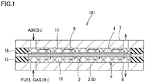
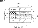
- Figs. 1 and 2 conceptually show a cell structure (fuel cell unit) 101 of a solid oxide fuel cell. It should be noted that, although Fig. 1 shows one cell structure, a fuel cell is generally composed by stacking a plurality of cell units in a thickness direction to increase a voltage for power generation.
- Fuel cell unit 101 includes a membrane electrode assembly 5 having a cathode layer 4 as an air electrode and an anode layer 3 as a fuel electrode, with a solid electrolyte layer 2 being sandwiched therebetween.
- Solid electrolyte layer 2 can be constituted of, for example, LSGM (lanthanum gallate), YSZ (Yttria Stabilized Zirconia), GDC (Gadolinium Doped Ceria), or the like.
- Cathode layer 4 in accordance with the present embodiment is formed by integrally firing a cathode material in a predetermined region on one side of solid electrolyte layer 2.
- anode layer 3 is provided by stacking a porous anode member 8 made of a metal porous body on the other side of solid electrolyte layer 2 to be pressed thereagainst.
- a current collecting member 7 On the outside of cathode layer 4 of membrane electrode assembly 5, a current collecting member 7 is provided, with a current collector 9 made of a metal porous body being interposed therebetween.
- Current collector 9 is constituted of a metal porous body having a high porosity, and serves as a gas flow channel 11.
- anode layer 3 of membrane electrode assembly 5 On the outside of anode layer 3 of membrane electrode assembly 5, a current collecting member 6 is provided to be directly stacked on anode layer 3.
- anode layer 3 is constituted of a metal porous body, and thereby serves as a gas flow channel 10 and also as a current collector.
- Current collector 9 and porous anode member 8 are constituted of porous bodies having electrical conductivity, and diffuse gases flowing through gas flow channels 10, 11 provided in these members to cathode layer 4 and solid electrolyte layer 2 to act thereon.
- Current collector 9 is configured to electrically connect cathode layer 4 and current collecting member 7 for electrical conduction therebetween.
- porous anode member 8 is configured to electrically connect solid electrolyte layer 2 and current collecting member 6 for electrical conduction therebetween.
- Fuel cell unit 101 is composed by stacking current collector 9, current collecting member 7, porous anode member 8, and current collecting member 6 on both sides of membrane electrode assembly 5, and sealing peripheral edge portions with gaskets 15, 16.
- Air containing oxygen as an oxidizer is introduced into gas flow channel 11, and oxygen is supplied to cathode layer 4 through current collector 9.
- a fuel gas containing hydrogen as a fuel is introduced into gas flow channel 10, and hydrogen is supplied to solid electrolyte layer 2 through porous anode member 8 which serves as anode layer 3.
- solid electrolyte layer 2 and cathode layer 4 are illustrated to be thicker than in reality for ease of understanding.
- Cathode layer 4 can be constituted of, for example, SSC (Sm 0.5 Sr 0. 5CoO 3 ), LSCF (Lanthanum Strontium Cobalt Ferrite), LSM (Lanthanum Strontium Manganate), BSCF (BaSrCoFe-based oxide), or the like.
- current collector 9 can be constituted of a variety of porous bodies having electrical conductivity.
- current collector 9 can also be constituted of the same metal porous body as that for porous anode member 8.
- Cathode layer 4 is an oxygen electrode, and its vicinity serves as a strong corrosive environment. Accordingly, cathode layer 4 and current collector 9 are preferably formed of materials having a high corrosion resistance.
- anode layer 3 is a fuel electrode, and its vicinity serves as a reducing atmosphere. Accordingly, porous anode member 8 is not required to be as corrosion resistant as cathode layer 4.
- anode layer 3 is composed by stacking porous anode member 8 made of a metal porous body on solid electrolyte layer 2 to be pressed thereagainst.
- solid electrolyte layer 2 and anode layer 3 are not integrally fired in the present embodiment, there occurs no reaction between constituent materials at a boundary surface between these layers during a firing step and the like, preventing an increase in electric resistance and a decrease in ionic conductivity.
- anode layer 3 can also serve as a current collector, the number of parts can also be reduced.
- anode layer 3 is stacked on solid electrolyte layer 2 to be pressed thereagainst. Therefore, even when there is a large difference in thermal expansion coefficient and the like between these members, there is no possibility that a crack or the like resulting from the thermal expansion coefficient and the like may occur as in the case of integral firing, and thus a high-quality fuel cell can be configured.
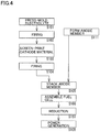
- a solid electrolyte material (LSGM: lanthanum gallate) was press-molded (S101 in Fig. 4 ) to form a plate-shaped solid electrolyte molded body, which was fired at 1500°C for 5 hours (S102 in Fig. 4 ) to form 300- ⁇ m-thick plate-shaped solid electrolyte layer 2.
- LSGM lanthanum gallate
- a cathode material (SSC: Sm 0.5 Sr 0.5 CoO 3 ) was applied onto the fired solid electrolyte molded body by screen printing (S103 in Fig. 4 ), and firing was performed thereon at 950°C for 0.5 hours (S104 in Fig. 4 ) to form 40- ⁇ m-thick cathode layer 4 integrally with solid electrolyte layer 2.
- Porous anode member 8 had a porosity of 96%, a thickness of 1 mm, and a basis weight of 400 g/m 2 .
- Fuel cell unit 101 was assembled by stacking current collecting member 7, current collector 9, solid electrolyte layer 2 provided with cathode layer 4, porous anode member 8, and current collecting member 6, and pressing porous anode member 8 against solid electrolyte layer 2 (S105 and S106 in Fig. 4 ). Porous anode member 8 was stacked on solid electrolyte layer 2 with its thickness being decreased by 5% due to a pressing force. Porous anode member 8 was stacked to be pressed in a state where plastic deformation occurred in the vicinity of interfaces with solid electrolyte layer 2 and current collecting member 6.
- Obtained fuel cell unit 101 was heated to 1000°C to be reduced (S107 in Fig. 4 ), and thereafter a performance test was conducted with each of hydrogen gas (H 2 100%) and air being introduced at 100 cc/min (S108 in Fig. 4 ).
- the fuel cell unit using a membrane electrode assembly in accordance with Example 1 was able to obtain an output of 206 mW/cm 2 .
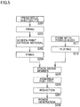
- Solid electrolyte layer 2 having the same configuration as that in Example 1 was formed by the same step as that in Example 1 (S201 to S202 in Fig. 5 ).
- Cathode layer 4 having the same configuration as that in Example 1 was formed by the same step as that in Example 1 (S203 to S204 in Fig. 5 ).
- a metal porous body having the same configuration as that in Example 1 was formed with the same technique as that in Example 1 (S211 in Fig. 5 ).
- This metal porous body was plated with 5- ⁇ m-thick Co-Ni plating to obtain porous anode member 8 (S212 in Fig. 5 ).
- the component composition of the above Co-Ni plating was set such that the mass ratio of the Co component to the Ni component was 3 to 1.
- porous anode member 8 As in Example 1, fuel cell unit 101 was assembled, with porous anode member 8 being pressed against solid electrolyte layer 2 (S205, S206 in Fig. 5 ). Porous anode member 8 was stacked on solid electrolyte layer 2 with its thickness being decreased by 5% due to a pressing force. As in Example 1, porous anode member 8 was stacked to be pressed in a state where plastic deformation occurred in the vicinity of interfaces with solid electrolyte layer 2 and current collecting member 6.
- Obtained fuel cell unit 101 was heated to 1000°C to be reduced (S207 in Fig. 5 ), and a performance test was conducted (S208 in Fig. 5 ). The performance test was conducted under the same conditions as those in Example 1.
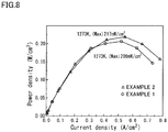
- Fig. 8 shows the fuel cell unit using a membrane electrode assembly in accordance with Example 2.
- Fig. 8 also shows the performance curve of the fuel cell unit using the membrane electrode assembly in accordance with Example 1.
- the output of the fuel cell unit using the membrane electrode assembly in accordance with Example 2 was higher than the output of the fuel cell unit using the membrane electrode assembly in accordance with Example 1 (206 mW/cm 2 ). This is considered to be because the Co-Ni plating increases electrical conductivity and improves the catalytic activity in porous anode member 8.
- Solid electrolyte layer 2 having the same configuration as that in Example 1 was formed by the same step as that in Example 1 (S201 to S202 in Fig. 5 ).
- Cathode layer 4 having the same configuration as that in Example 1 was formed by the same step as that in Example 1 (S203 to S204 in Fig. 5 ).
- a metal porous body having the same configuration as that in Example 1 was formed with the same technique as that in Example 1 (S211 in Fig. 5 ).
- This metal porous body was plated with 5- ⁇ m-thick Mn-Co plating to obtain porous anode member 8 (S212 in Fig. 5 ).
- the component composition of the above Mn-Co plating was set such that the mass ratio of the Mn component to the Co component was 9 to 1.
- porous anode member 8 As in Example 1, fuel cell unit 101 was assembled, with porous anode member 8 being pressed against solid electrolyte layer 2 (S205, S206 in Fig. 5 ). Porous anode member 8 was stacked on solid electrolyte layer 2 with its thickness being decreased by 5% due to a pressing force. As in Example 1, porous anode member 8 was stacked to be pressed in a state where plastic deformation occurred in the vicinity of interfaces with solid electrolyte layer 2 and current collecting member 6.
- Obtained fuel cell unit 101 was heated to 1000°C to be reduced (S207 in Fig. 5 ), and a performance test was conducted (S208 in Fig. 5 ). The performance test was conducted under the same conditions as those in Example 1.
- Fig. 9 shows the fuel cell unit using a membrane electrode assembly in accordance with Example 3.
- Fig. 9 also shows the performance curve of the fuel cell unit using the membrane electrode assembly in accordance with Example 1.
- the output of the fuel cell unit using the membrane electrode assembly in accordance with Example 3 was higher than the output of the fuel cell unit using the membrane electrode assembly in accordance with Example 1 (206 mW/cm 2 ). This is considered to be because the Mn-Co plating increases electrical conductivity and improves the catalytic activity in porous anode member 8.
- the output of the fuel cell unit using the membrane electrode assembly in accordance with Example 3 was higher than the output of the fuel cell unit in accordance with Example 2 shown in Fig. 8 . This is considered to be because the catalytic activity of the Mn-Co plating is higher than the catalytic activity of the Co-Ni plating.
- Solid electrolyte layer 2 having the same configuration as that in Example 1 was formed by the same step as that in Example 1 (S301 to S302 in Fig. 6 ).
- Cathode layer 4 having the same configuration as that in Example 1 was formed by the same step as that in Example 1 (S303 to S304 in Fig. 6 ).
- a metal porous body having the same configuration as that in Example 1 was formed with the same technique as that in Example 1 (S311 in Fig. 6 ).
- This metal porous body was filled with a catalyst made of NiO (S312 in Fig. 6 ).
- the catalyst had an average particle diameter of 1 ⁇ m, and the fill amount was set to 80 to 90 vol%.
- porous anode member 8 As in Example 1, fuel cell unit 101 was assembled, with porous anode member 8 being pressed against solid electrolyte layer 2 (S305, S306 in Fig. 6 ). Porous anode member 8 was stacked on solid electrolyte layer 2 with its thickness being decreased by 5% due to a pressing force. As in Example 1, porous anode member 8 was stacked to be pressed in a state where plastic deformation occurred in the vicinity of interfaces with solid electrolyte layer 2 and current collecting member 6.
- Obtained fuel cell unit 101 was heated to 1000°C to be reduced (S307 in Fig. 6 ), and a performance test was conducted (S308 in Fig. 6 ). The performance test was conducted under the same conditions as those in Example 1.
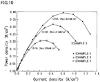
- Fig. 10 shows the fuel cell unit using a membrane electrode assembly in accordance with Example 4, and the performance curve of the fuel cell unit using the membrane electrode assembly in accordance with Example 3.
- the output of the fuel cell unit using the membrane electrode assembly in accordance with Example 4 was higher than the outputs of the fuel cell units using the membrane electrode assemblies in accordance with Examples 1 and 3 (206 mW/cm 2 and 311 mW/cm 2 , respectively). This is considered to be because the filled NiO is reduced during power generation and has a high activity as a catalyst.
Landscapes
- Chemical & Material Sciences (AREA)
- Chemical Kinetics & Catalysis (AREA)
- General Chemical & Material Sciences (AREA)
- Electrochemistry (AREA)
- Engineering & Computer Science (AREA)
- Manufacturing & Machinery (AREA)
- Sustainable Development (AREA)
- Sustainable Energy (AREA)
- Life Sciences & Earth Sciences (AREA)
- Materials Engineering (AREA)
- Composite Materials (AREA)
- Ceramic Engineering (AREA)
- Fuel Cell (AREA)
- Inert Electrodes (AREA)
Abstract
Description
- The present invention relates to a membrane electrode assembly, a method for manufacturing a membrane electrode assembly, a fuel cell, and a method for manufacturing a fuel cell. Specifically, the present invention relates to a membrane electrode assembly and the like capable of improving performance of a fuel cell and capable of reducing the number of parts and manufacturing cost.
- A solid oxide fuel cell (hereinafter referred to as an "SOFC") includes an electrolyte-electrode stacked body having an anode layer and a cathode layer provided on both sides of a solid electrolyte layer. In order to reduce ionic conduction resistance in the solid electrolyte layer, it is considered preferable to form the solid electrolyte layer to have a thickness as thin as possible. On the other hand, when the solid electrolyte layer is thinly formed, the solid electrolyte layer has a reduced strength, which may cause a trouble during a manufacturing process or during use. Accordingly, there is often adopted a structure in which an anode layer to be stacked on a solid electrolyte layer is set to be thick, and the solid electrolyte layer is integrally formed on the anode layer to secure strength as a stacked body (i.e., an anode support structure) [Japanese Patent Laying-Open No.
2012-099497 - The electrolyte-electrode stacked body described above is often manufactured by thinly applying electrolyte powder onto an anode layer powder compact and simultaneously firing this electrolyte-anode stacked body.
- PTD 1: Japanese Patent Laying-Open No.
2012-099497 - By adopting the above configuration, the strength of the electrolyte-anode stacked body can be secured, while setting the solid electrolyte layer to have a small thickness. However, due to the high firing temperature of the solid electrolyte layer, members constituting the anode layer and the solid electrolyte layer react at an interface therebetween during firing, causing problems such as a decrease in ionic conductivity and an increase in electric resistance.
- Further, when the above configuration of integrally firing the solid electrolyte layer and the anode layer is adopted, it is necessary to match firing behaviors, such as shrinkage rates, between the solid electrolyte layer and the anode layer. Accordingly, combination of materials constituting the solid electrolyte layer and the anode layer is limited, and performance of the fuel cell cannot be improved.
- Furthermore, with a conventional technique, steps for manufacturing the above electrolyte-electrode stacked body and the numbers of parts are increased, causing a problem such as an increase in manufacturing cost.
- The present invention has been conceived to solve the aforementioned problems, and one object of the present invention is to provide a membrane electrode assembly capable of improving performance of a fuel cell and capable of reducing manufacturing steps and the number of parts, as well as a method for manufacturing the membrane electrode assembly. Further, another object of the present invention is to provide a fuel cell including the membrane electrode assembly, as well as a method for manufacturing a fuel cell including the method for manufacturing the membrane electrode assembly.
- A membrane electrode assembly in accordance with a first aspect of the present invention is a membrane electrode assembly including a solid electrolyte layer, an anode layer provided on one side of the solid electrolyte layer, and a cathode layer provided on the other side of the solid electrolyte layer, the anode layer being stacked on the solid electrolyte layer to be pressed thereagainst, the anode layer including a porous anode member having electrical conductivity.
- A fuel cell in accordance with a second aspect of the present invention includes the membrane electrode assembly in accordance with the first aspect described above.
- A method for manufacturing a membrane electrode assembly in accordance with a third aspect of the present invention is a method for manufacturing a membrane electrode assembly including a solid electrolyte layer, an anode layer provided on one side of the solid electrolyte layer, and a cathode layer provided on the other side of the solid electrolyte layer, including the steps of forming the solid electrolyte layer, forming the cathode layer on the other side of the solid electrolyte layer, preparing a porous anode member, and stacking the porous anode member on the one side of the solid electrolyte layer to be pressed thereagainst.
- A method for manufacturing a fuel cell in accordance with a fourth aspect of the present invention includes the method for manufacturing the membrane electrode assembly in accordance with the third aspect described above.
- According to the above invention, performance of the fuel cell can be improved, and manufacturing steps and the number of parts can be reduced. Further, manufacturing cost can be reduced.
-
-
Fig. 1 is a cross sectional view showing a schematic configuration of a fuel cell unit in accordance with one embodiment. -
Fig. 2 is an enlarged cross sectional view of a main portion inFig. 1 . -
Fig. 3 is a cross sectional view showing a stacked form of a membrane electrode assembly in accordance with one embodiment. -
Fig. 4 is a flowchart showing a method for manufacturing a membrane electrode assembly and a fuel cell unit in accordance with Example 1. -
Fig. 5 is a flowchart showing a method for manufacturing membrane electrode assemblies and fuel cell units in accordance with Examples 2 and 3. -
Fig. 6 is a flowchart showing a method for manufacturing a membrane electrode assembly and a fuel cell unit in accordance with Example 4. -
Fig. 7 is a graph showing performance of the fuel cell unit composed using the membrane electrode assembly in accordance with Example 1. -
Fig. 8 is a graph showing performance of the fuel cell unit composed using the membrane electrode assembly in accordance with Example 2 in comparison with the performance of the fuel cell unit composed using the membrane electrode assembly in accordance with Example 1. -
Fig. 9 is a graph showing performance of the fuel cell unit composed using the membrane electrode assembly in accordance with Example 3 in comparison with the performance of the fuel cell unit composed using the membrane electrode assembly in accordance with Example 1. -
Fig. 10 is a graph showing performance of the fuel cell unit composed using the membrane electrode assembly in accordance with Example 4 in comparison with the performance of the fuel cell unit composed using the membrane electrode assembly in accordance with Example 1 and the performance of the fuel cell unit composed using the membrane electrode assembly in accordance with Example 3. - A membrane electrode assembly in accordance with one embodiment of the present invention is a membrane electrode assembly including a solid electrolyte layer, an anode layer provided on one side of the solid electrolyte layer, and a cathode layer provided on the other side of the solid electrolyte layer, the anode layer being stacked on the solid electrolyte layer to be pressed thereagainst, the anode layer including a porous anode member having electrical conductivity.
- Since the solid electrolyte layer and the anode layer are not integrally fired in the present embodiment, there occurs no reaction between constituent materials at a boundary surface between these layers during a firing step and the like, preventing an increase in electric resistance and a decrease in ionic conductivity.
- Further, since there is no need to fire the solid electrolyte layer together with the anode layer, manufacturing steps can be reduced. Furthermore, since the anode layer can also serve as a current collector, the number of parts can also be reduced.
- Furthermore, the solid electrolyte layer and the anode layer are stacked to be pressed against each other. Therefore, even when there is a large difference in thermal expansion coefficient and the like between these members, there is no possibility that a crack or the like resulting from the thermal expansion coefficient and the like may occur as in the case of integral firing, and thus a high-quality fuel cell can be configured.
- Moreover, there is also no need to set behaviors during firing, thermal expansion coefficients, and the like of materials constituting the solid electrolyte layer and the anode layer to be identical. Accordingly, the range of choices for the materials constituting the solid electrolyte layer and the anode layer is significantly widened. As a result, the solid electrolyte layer and the anode layer can be formed of optimal materials, and performance of the fuel cell can also be improved.
- Since the solid electrolyte layer is generally formed without being held on the anode layer in the present embodiment, the solid electrolyte layer preferably has a predetermined strength. Accordingly, it is preferable to set the solid electrolyte layer to have a thickness somewhat larger than that in a case where the anode support structure is adopted. On the other hand, an increase in the thickness of the solid electrolyte layer may cause an increase in electric resistance and a decrease in ionic conductivity. However, with the progress of material technology in recent years, setting the solid electrolyte layer to have a larger thickness does not result in a significant decrease in electrical conductivity and ionic conductivity. In the present embodiment, the solid electrolyte layer is preferably set to have a thickness of 0.1 to 1 mm in order to secure the strength of the solid electrolyte layer.
- The material constituting the solid electrolyte layer is not particularly limited, and any solid electrolyte material constituted of a variety of materials can be adopted as long as it is formed by a firing method. For example, LSGM (lanthanum gallate), YSZ (Yttria Stabilized Zirconia), GDC (Gadolinium Doped Ceria), or the like can be adopted.
- The material constituting the cathode layer is also not particularly limited, and any material can be adopted as long as it can be fired after being stacked on the solid electrolyte layer. For example, SSC (Sm0.5Sr0.5CoO3), LSCF (Lanthanum Strontium Cobalt Ferrite), or the like can be adopted.
- Further, there can also be adopted a configuration in which the strength of a solid electrolyte-cathode stacked body is increased by setting the cathode layer to have an increased thickness or strength.
- The anode layer in accordance with the present embodiment can be configured to include a variety of porous anode members having electrical conductivity and capable of serving as an anode electrode and also as a current collector when being pressed against the solid electrolyte layer. For example, a porous body constituted of carbon fibers or the like, or a metal porous body constituted of Ni or the like can be adopted. By adopting a metal porous body as a porous anode member, high heat resistance and electrical conductivity can be secured.
- Further, as the porous anode member, a member which can be pressed against the solid electrolyte layer in a state where its solid electrolyte layer side is compressively deformed by a predetermined amount is preferably adopted, such that required electrical conductivity can be exhibited and a large force is not exerted on a local portion of the solid electrolyte layer or the like when the porous anode member is stacked to be pressed against the solid electrolyte layer. For example, the porous anode member can be constituted of a sheet-shaped porous body having a high porosity. When the sheet-shaped porous body having a high porosity is compressed from both side surfaces, the sheet-shaped porous body is significantly deformed in the vicinity of the compressed surfaces. In particular, in the case of a metal porous body, with an increase in compressive force, plastic deformation occurs from the vicinity of the compressed surfaces. The occurrence of plastic deformation in the vicinity of an interface in contact with the solid electrolyte layer prevents a large force from being locally exerted, and thereby the compressive force exerted on the solid electrolyte layer is uniformized and damage to the solid electrolyte layer can be prevented. Further, since contact pressure can be uniformized, good electrical conductivity can be secured throughout the surface of the solid electrolyte layer. Furthermore, since the metal porous body is stacked in a state where a portion thereof in contact with the solid electrolyte layer is collapsed, its contact area with respect to the solid electrolyte layer is increased and its contact resistance is decreased, leading to an increase in electrical conductivity. On the other hand, since the porosity of an intermediate portion in a thickness direction is higher than that in the vicinity of the interface, a significant decrease in gas flow resistance does not occur. In order to secure required electrical conductivity, it is preferable to stack the porous anode member such as a metal porous body to be pressed in a state where deformation in the thickness direction including elastic deformation and plastic deformation is 2 to 10%. It is also preferable that the porous anode member is stacked on the solid electrolyte layer in a state where the porous anode member is compressively deformed by being pressed against the solid electrolyte layer at a pressure of 5 to 50 N/cm2.
- The porous anode member can be constituted of a metal porous body having electrical conductivity. As the metal porous body, a metal porous body formed of a variety of materials having electrical conductivity can be adopted. For example, the metal porous body can be formed of a material selected from nickel (Ni), a nickel (Ni)-tin (Sn) alloy, a nickel (Ni)-tin (Ni)-chromium (Cr) alloy, a ferrite-based stainless alloy, an inconel (Ni-base) alloy, and the like.
- The form of the metal porous body is also not particularly limited. For example, a metal porous body in the shape of a sheet formed by knitting or interlacing metal fibers can be adopted.
- Further, as the metal porous body, a metal porous body that includes a skeleton having outer shells and a core portion made of one or both of a hollow material or an electrically conductive material, and includes a three-dimensional network structure in which the skeleton integrally continues, can be adopted.
- A porous base material including a three-dimensional network structure can have a high porosity, and also has a high electrical conductivity because its skeleton integrally continues. When the porous base material including a three-dimensional network structure is used, pores can be formed with a uniform pore diameter. Accordingly, gas flow resistance can be reduced, and the efficiency of the fuel cell can be improved. Further, when the porous base material including a three-dimensional network structure is used, porosity and pore diameter can be easily adjusted. Accordingly, the porous base material can secure the function of diffusing gas to the solid electrolyte layer, and can serve as a gas flow channel. In addition, when the porous base material including a three-dimensional network structure is used, the porous base material, upon being compressively deformed, is plastically deformed in the vicinity of a compressed surface. Accordingly, the porous base material can obtain a high electrical conductivity while preventing a large force from being exerted on a local portion of the solid electrolyte layer.
- The porous anode member can be stacked to be directly pressed against the surface of the solid electrolyte layer, or can be stacked to be pressed against the surface of the solid electrolyte layer with a member formed of a variety of electrically conductive materials being interposed therebetween. For example, the porous anode member can be stacked to be pressed against the surface of the solid electrolyte layer with a soft porous body or powder having a higher electrical conductivity being interposed therebetween. For example, the porous anode member can be stacked to be pressed against the surface of the solid electrolyte layer with silver powder, silver paste, or the like being interposed therebetween.
- The technique of holding the stacked state of the porous anode member is also not particularly limited. For example, the porous anode member can be pressed against the surface of the solid electrolyte layer with a constituent member of the fuel cell, such as a separator, being interposed therebetween.
- When the porous anode member is assembled into the fuel cell, the porous anode member can be stacked to be pressed against the solid electrolyte layer, or the porous anode member can be held beforehand in a stacked state on the surface of the solid electrolyte layer and then a pressing force can be exerted thereon during assembly. For example, the solid electrolyte layer and the porous anode member can be temporarily fixed with an adhesive component such as silver paste, and then a pressing force can be exerted thereon when they are assembled into the fuel cell.
- The porous anode member can be provided with a surface coating layer for improving corrosion resistance and electrical conductivity. The technique of providing the surface coating layer is not particularly limited, and the surface coating layer can be formed for example by a plating method or the like. For example, manganese cobalt plating or cobalt nickel plating can be applied. Thereby, performance and durability of the fuel cell can be improved.
- The porous anode member can also be caused to hold a catalytic component. For example, a catalytic component such as: a single metal such as Ni, Fe, Co, Ag, Pt, or Pd, or an alloy thereof; a single ionic conductor such as YSZ (Yttria Stabilized Zirconia), GDC (Gadolinium Doped Ceria), LSGM (lanthanum gallate), SSZ (Scandia Stabilized Zirconia), BCY (Yttrium-doped Barium Cerate), or BZY (Yttrium-doped Barium Zirconate), or a composite thereof; or a composite of a metal or an alloy and an ionic conductor can be held in pores of the porous anode member. Thereby, power generation performance of the fuel cell can be improved.
- The membrane electrode assembly can be manufactured by a method including a solid electrolyte layer formation step of forming the solid electrolyte layer, a cathode layer formation step of forming the cathode layer on the other side of the solid electrolyte layer, the step of preparing the porous anode member, and an anode member stacking step of stacking the porous anode member on a porous anode member side of the solid electrolyte layer to be pressed thereagainst. In the present embodiment, the porous anode member can also serve as a current collector. Further, there is no need to sinter the anode layer together with the solid electrolyte layer. Accordingly, the number of parts and manufacturing steps are reduced.
- The solid electrolyte layer formation step can include a variety of techniques and steps. The solid electrolyte layer formation step can include, for example, the step of compression-molding a powder-shaped solid electrolyte material, and the step of firing the compression-molded solid electrolyte material.
- The cathode layer formation step can be performed by applying a cathode layer formation material by a predetermined thickness onto one surface of the fired solid electrolyte layer, and firing the cathode layer formation material. Since the cathode material can be fired at a temperature lower than the firing temperature of the solid electrolyte material, there is no possibility that the solid electrolyte material may be deformed or the like. Further, the cathode material can also be applied onto a surface of a solid electrolyte material molded body before being fired, and then fired simultaneously.
- The step of preparing the porous anode member can include a variety of steps depending on the porous material adopted for the anode layer. For example, the step of preparing the porous anode member can include the step of forming a sheet-shaped porous anode member by knitting or interlacing fibers having electrical conductivity.
- Alternatively, the step of preparing the porous anode member can include the step of manufacturing a metal porous body that includes a skeleton having outer shells and a core portion made of one or both of a hollow material or an electrically conductive material, and includes a three-dimensional network structure in which the skeleton integrally continues. The step of preparing the porous anode member may be the step of preparing a commercially available product. As the commercially available product, for example, a metal porous body manufactured by Sumitomo Electric Industries (registered trademark: Celmet) can be adopted.
- For example, when a metal porous body constituted of Ni is manufactured, the step of preparing the porous anode member can include the step of performing electrical conduction treatment on a three-dimensional network-shaped resin porous base material to form an electrically conductive layer in a surface thereof, an Ni-plated layer formation step of forming an Ni-plated layer on the electrically conductive layer, a base material disappearance step of making the resin porous base material disappear in an atmosphere in which at least oxygen is present, and a reduction step of subjecting the remaining layers to a temperature of 300°C to 1100°C in a reducing atmosphere.
- The metal porous body having the above structure can have a high porosity, because its skeleton has a three-dimensional network structure. Further, with the metal porous body having the above structure, a metal porous body having a required porosity can be easily formed. In addition, since the metal porous body can be formed to have pores with a substantially constant pore diameter, the metal porous body has a high gas diffusivity, and can cause gas to uniformly act on the solid electrolyte layer. The metal porous body having a high porosity can serve not only as an anode layer but also as a gas flow channel.
- Further, as the metal porous body, a metal porous body which can be easily deformed is preferably adopted, such that electrical conductivity is increased and the solid electrolyte layer is not damaged when the metal porous body is pressed against the solid electrolyte layer. Since the metal porous body having the above three-dimensional network structure has a constant pore diameter, a pressing force does not concentrate on a local portion of the solid electrolyte layer. In addition, by setting the metal porous body to have a small basis weight, a metal porous body which can be easily deformed in the vicinity of its surface in contact with the solid electrolyte layer can be obtained. For example, it is preferable to adopt a metal porous body having a basis weight of 200 to 500 g/m2.
- Since the fuel cell is operated at a high temperature, a member constituting the anode layer preferably has a predetermined corrosion resistance in order to improve durability. In this case, the step of preparing the porous anode member can include the step of forming a metal porous body and the step of forming a coating layer on a surface of the metal porous body. For example, the step of preparing the porous anode member can include the step of plating the metal porous body with a corrosion-resistant metal or the like, or an alloying step for improving corrosion resistance. For example, the step of preparing the porous anode member can include a plating step of applying manganese cobalt plating or cobalt nickel plating to the metal porous body. Further, the step of preparing the porous anode member can also include, for example, the step of performing alloying with Sn on the metal porous body, in order to improve corrosion resistance.
- In addition, as described above, the step of preparing the porous anode member can include the step of causing the porous anode member to hold a catalyst.
- The anode member stacking step can be performed with a variety of techniques. For example, in the step of assembling the fuel cell, the porous anode member can be stacked on the solid electrolyte layer to be pressed thereagainst, using a separator or the like. Further, before being assembled into the fuel cell, the porous anode member can be stacked on the solid electrolyte layer to be pressed thereagainst, using a jig or the like. In this case, the anode layer (porous anode member) and the solid electrolyte layer can be temporarily fixed with an adhesive component such as silver paste, and held in a stacked state.
- In the anode member stacking step, the porous anode member is preferably stacked to be deformed at least in the vicinity of the solid electrolyte layer. This can increase electrical conductivity with the solid electrolyte layer, and improve performance of the fuel cell. Further, this can decrease the porosity of the porous anode member on the solid electrolyte layer side, and can increase the action of diffusing gas in the vicinity of the solid electrolyte layer.
- Hereinafter, details of an embodiment will be described based on the drawings.
-
Figs. 1 and2 conceptually show a cell structure (fuel cell unit) 101 of a solid oxide fuel cell. It should be noted that, althoughFig. 1 shows one cell structure, a fuel cell is generally composed by stacking a plurality of cell units in a thickness direction to increase a voltage for power generation. -
Fuel cell unit 101 includes amembrane electrode assembly 5 having acathode layer 4 as an air electrode and ananode layer 3 as a fuel electrode, with asolid electrolyte layer 2 being sandwiched therebetween.Solid electrolyte layer 2 can be constituted of, for example, LSGM (lanthanum gallate), YSZ (Yttria Stabilized Zirconia), GDC (Gadolinium Doped Ceria), or the like. -
Cathode layer 4 in accordance with the present embodiment is formed by integrally firing a cathode material in a predetermined region on one side ofsolid electrolyte layer 2. On the other hand,anode layer 3 is provided by stacking aporous anode member 8 made of a metal porous body on the other side ofsolid electrolyte layer 2 to be pressed thereagainst. - On the outside of
cathode layer 4 ofmembrane electrode assembly 5, acurrent collecting member 7 is provided, with acurrent collector 9 made of a metal porous body being interposed therebetween.Current collector 9 is constituted of a metal porous body having a high porosity, and serves as agas flow channel 11. - On the outside of
anode layer 3 ofmembrane electrode assembly 5, acurrent collecting member 6 is provided to be directly stacked onanode layer 3. In the present embodiment,anode layer 3 is constituted of a metal porous body, and thereby serves as agas flow channel 10 and also as a current collector. -
Current collector 9 andporous anode member 8 are constituted of porous bodies having electrical conductivity, and diffuse gases flowing throughgas flow channels cathode layer 4 andsolid electrolyte layer 2 to act thereon.Current collector 9 is configured to electrically connectcathode layer 4 and current collectingmember 7 for electrical conduction therebetween. Further,porous anode member 8 is configured to electrically connectsolid electrolyte layer 2 and current collectingmember 6 for electrical conduction therebetween. -
Fuel cell unit 101 is composed by stackingcurrent collector 9, current collectingmember 7,porous anode member 8, and current collectingmember 6 on both sides ofmembrane electrode assembly 5, and sealing peripheral edge portions withgaskets - Air containing oxygen as an oxidizer is introduced into
gas flow channel 11, and oxygen is supplied tocathode layer 4 throughcurrent collector 9. A fuel gas containing hydrogen as a fuel is introduced intogas flow channel 10, and hydrogen is supplied tosolid electrolyte layer 2 throughporous anode member 8 which serves asanode layer 3. - In
anode layer 3, in the vicinity of the solid electrolyte layer, a reaction represented by H2 → 2H+ + 2e- occurs. On the other hand, incathode layer 4, a reaction represented by 1/2O2 + 2H+ + 2e- → H2O occurs. Thereby, hydrogen ions move fromanode layer 3, throughsolid electrolyte layer 2, tocathode layer 4, and electrons flow fromporous anode member 8 to current collectingmember 6, current collectingmember 7,current collector 9, andcathode layer 4, and thus electric power is obtained. It should be noted thatfuel cell unit 101 is heated to a predetermined temperature with a heating device not shown. - In
Fig. 1 ,solid electrolyte layer 2 andcathode layer 4 are illustrated to be thicker than in reality for ease of understanding. -
Cathode layer 4 can be constituted of, for example, SSC (Sm0.5Sr0.5CoO3), LSCF (Lanthanum Strontium Cobalt Ferrite), LSM (Lanthanum Strontium Manganate), BSCF (BaSrCoFe-based oxide), or the like. Further,current collector 9 can be constituted of a variety of porous bodies having electrical conductivity. For example,current collector 9 can also be constituted of the same metal porous body as that forporous anode member 8. -
Cathode layer 4 is an oxygen electrode, and its vicinity serves as a strong corrosive environment. Accordingly,cathode layer 4 andcurrent collector 9 are preferably formed of materials having a high corrosion resistance. On the other hand,anode layer 3 is a fuel electrode, and its vicinity serves as a reducing atmosphere. Accordingly,porous anode member 8 is not required to be as corrosion resistant ascathode layer 4. In the present embodiment,anode layer 3 is composed by stackingporous anode member 8 made of a metal porous body onsolid electrolyte layer 2 to be pressed thereagainst. - Since
solid electrolyte layer 2 andanode layer 3 are not integrally fired in the present embodiment, there occurs no reaction between constituent materials at a boundary surface between these layers during a firing step and the like, preventing an increase in electric resistance and a decrease in ionic conductivity. - Further, since there is no need to fire
solid electrolyte layer 2 together withanode layer 3, manufacturing steps can be reduced. Furthermore, sinceanode layer 3 can also serve as a current collector, the number of parts can also be reduced. - Furthermore, as shown in
Fig. 3 ,anode layer 3 is stacked onsolid electrolyte layer 2 to be pressed thereagainst. Therefore, even when there is a large difference in thermal expansion coefficient and the like between these members, there is no possibility that a crack or the like resulting from the thermal expansion coefficient and the like may occur as in the case of integral firing, and thus a high-quality fuel cell can be configured. - Moreover, there is also no need to set behaviors during firing, thermal expansion coefficients, and the like of the materials constituting
solid electrolyte layer 2 andanode layer 3 to be identical. Accordingly, the range of choices for the materials constitutingsolid electrolyte layer 2 andanode layer 3 is significantly widened. As a result,solid electrolyte layer 2 andanode layer 3 can be constituted of optimal materials, and performance offuel cell unit 101 and the fuel cell including the same can also be improved. - As shown in
Fig. 4 , a solid electrolyte material (LSGM: lanthanum gallate) was press-molded (S101 inFig. 4 ) to form a plate-shaped solid electrolyte molded body, which was fired at 1500°C for 5 hours (S102 inFig. 4 ) to form 300-µm-thick plate-shapedsolid electrolyte layer 2. - A cathode material (SSC: Sm0.5Sr0.5CoO3) was applied onto the fired solid electrolyte molded body by screen printing (S103 in
Fig. 4 ), and firing was performed thereon at 950°C for 0.5 hours (S104 inFig. 4 ) to form 40-µm-thick cathode layer 4 integrally withsolid electrolyte layer 2. - With the technique described above, a metal porous body having a three-dimensional network structure was formed from nickel to form porous anode member 8 (S111 in
Fig. 4 ).Porous anode member 8 had a porosity of 96%, a thickness of 1 mm, and a basis weight of 400 g/m2. -
Fuel cell unit 101 was assembled by stacking current collectingmember 7,current collector 9,solid electrolyte layer 2 provided withcathode layer 4,porous anode member 8, and current collectingmember 6, and pressingporous anode member 8 against solid electrolyte layer 2 (S105 and S106 inFig. 4 ).Porous anode member 8 was stacked onsolid electrolyte layer 2 with its thickness being decreased by 5% due to a pressing force.Porous anode member 8 was stacked to be pressed in a state where plastic deformation occurred in the vicinity of interfaces withsolid electrolyte layer 2 and current collectingmember 6. - Obtained
fuel cell unit 101 was heated to 1000°C to be reduced (S107 inFig. 4 ), and thereafter a performance test was conducted with each of hydrogen gas (H2 100%) and air being introduced at 100 cc/min (S108 inFig. 4 ). - As shown in
Fig. 7 , the fuel cell unit using a membrane electrode assembly in accordance with Example 1 was able to obtain an output of 206 mW/cm2. In particular, it was able to confirm that an output sufficient as an SOFC is obtained by stackingporous anode member 8 onsolid electrolyte layer 2 to be pressed thereagainst as described above. -
Solid electrolyte layer 2 having the same configuration as that in Example 1 was formed by the same step as that in Example 1 (S201 to S202 inFig. 5 ). -
Cathode layer 4 having the same configuration as that in Example 1 was formed by the same step as that in Example 1 (S203 to S204 inFig. 5 ). - A metal porous body having the same configuration as that in Example 1 was formed with the same technique as that in Example 1 (S211 in
Fig. 5 ). This metal porous body was plated with 5-µm-thick Co-Ni plating to obtain porous anode member 8 (S212 inFig. 5 ). It should be noted that the component composition of the above Co-Ni plating was set such that the mass ratio of the Co component to the Ni component was 3 to 1. - As in Example 1,
fuel cell unit 101 was assembled, withporous anode member 8 being pressed against solid electrolyte layer 2 (S205, S206 inFig. 5 ).Porous anode member 8 was stacked onsolid electrolyte layer 2 with its thickness being decreased by 5% due to a pressing force. As in Example 1,porous anode member 8 was stacked to be pressed in a state where plastic deformation occurred in the vicinity of interfaces withsolid electrolyte layer 2 and current collectingmember 6. - Obtained
fuel cell unit 101 was heated to 1000°C to be reduced (S207 inFig. 5 ), and a performance test was conducted (S208 inFig. 5 ). The performance test was conducted under the same conditions as those in Example 1. - As shown in
Fig. 8 , the fuel cell unit using a membrane electrode assembly in accordance with Example 2 was able to obtain an output of 217 mW/cm2. Further,Fig. 8 also shows the performance curve of the fuel cell unit using the membrane electrode assembly in accordance with Example 1. The output of the fuel cell unit using the membrane electrode assembly in accordance with Example 2 was higher than the output of the fuel cell unit using the membrane electrode assembly in accordance with Example 1 (206 mW/cm2). This is considered to be because the Co-Ni plating increases electrical conductivity and improves the catalytic activity inporous anode member 8. -
Solid electrolyte layer 2 having the same configuration as that in Example 1 was formed by the same step as that in Example 1 (S201 to S202 inFig. 5 ). -
Cathode layer 4 having the same configuration as that in Example 1 was formed by the same step as that in Example 1 (S203 to S204 inFig. 5 ). - A metal porous body having the same configuration as that in Example 1 was formed with the same technique as that in Example 1 (S211 in
Fig. 5 ). This metal porous body was plated with 5-µm-thick Mn-Co plating to obtain porous anode member 8 (S212 inFig. 5 ). It should be noted that the component composition of the above Mn-Co plating was set such that the mass ratio of the Mn component to the Co component was 9 to 1. - As in Example 1,
fuel cell unit 101 was assembled, withporous anode member 8 being pressed against solid electrolyte layer 2 (S205, S206 inFig. 5 ).Porous anode member 8 was stacked onsolid electrolyte layer 2 with its thickness being decreased by 5% due to a pressing force. As in Example 1,porous anode member 8 was stacked to be pressed in a state where plastic deformation occurred in the vicinity of interfaces withsolid electrolyte layer 2 and current collectingmember 6. - Obtained
fuel cell unit 101 was heated to 1000°C to be reduced (S207 inFig. 5 ), and a performance test was conducted (S208 inFig. 5 ). The performance test was conducted under the same conditions as those in Example 1. - As shown in
Fig. 9 , the fuel cell unit using a membrane electrode assembly in accordance with Example 3 was able to obtain an output of 311 mW/cm2. Further,Fig. 9 also shows the performance curve of the fuel cell unit using the membrane electrode assembly in accordance with Example 1. The output of the fuel cell unit using the membrane electrode assembly in accordance with Example 3 was higher than the output of the fuel cell unit using the membrane electrode assembly in accordance with Example 1 (206 mW/cm2). This is considered to be because the Mn-Co plating increases electrical conductivity and improves the catalytic activity inporous anode member 8. Further, the output of the fuel cell unit using the membrane electrode assembly in accordance with Example 3 was higher than the output of the fuel cell unit in accordance with Example 2 shown inFig. 8 . This is considered to be because the catalytic activity of the Mn-Co plating is higher than the catalytic activity of the Co-Ni plating. -
Solid electrolyte layer 2 having the same configuration as that in Example 1 was formed by the same step as that in Example 1 (S301 to S302 inFig. 6 ). -
Cathode layer 4 having the same configuration as that in Example 1 was formed by the same step as that in Example 1 (S303 to S304 inFig. 6 ). - A metal porous body having the same configuration as that in Example 1 was formed with the same technique as that in Example 1 (S311 in
Fig. 6 ). This metal porous body was filled with a catalyst made of NiO (S312 inFig. 6 ). The catalyst had an average particle diameter of 1 µm, and the fill amount was set to 80 to 90 vol%. - As in Example 1,
fuel cell unit 101 was assembled, withporous anode member 8 being pressed against solid electrolyte layer 2 (S305, S306 inFig. 6 ).Porous anode member 8 was stacked onsolid electrolyte layer 2 with its thickness being decreased by 5% due to a pressing force. As in Example 1,porous anode member 8 was stacked to be pressed in a state where plastic deformation occurred in the vicinity of interfaces withsolid electrolyte layer 2 and current collectingmember 6. - Obtained
fuel cell unit 101 was heated to 1000°C to be reduced (S307 inFig. 6 ), and a performance test was conducted (S308 inFig. 6 ). The performance test was conducted under the same conditions as those in Example 1. - As shown in
Fig. 10 , the fuel cell unit using a membrane electrode assembly in accordance with Example 4 was able to obtain an output of 401 mW/cm2. Further,Fig. 10 also shows the performance curve of the fuel cell unit using the membrane electrode assembly in accordance with Example 1, and the performance curve of the fuel cell unit using the membrane electrode assembly in accordance with Example 3. The output of the fuel cell unit using the membrane electrode assembly in accordance with Example 4 was higher than the outputs of the fuel cell units using the membrane electrode assemblies in accordance with Examples 1 and 3 (206 mW/cm2 and 311 mW/cm2, respectively). This is considered to be because the filled NiO is reduced during power generation and has a high activity as a catalyst. - It should be understood that the embodiment and examples disclosed herein are illustrative and non-restrictive in every respect. The scope of the present invention is defined by the scope of the claims, rather than the description above, and is intended to include any modifications within the scope and meaning equivalent to the scope of the claims.
- 2: solid electrolyte layer; 3: anode layer; 4: cathode layer; 5: membrane electrode assembly; 6: current collecting member; 7: current collecting member; 8: porous anode member; 9: current collector; 10: gas flow channel; 11: gas flow channel; 15: gasket; 16: gasket; 101 fuel cell unit.
Claims (15)
- A membrane electrode assembly, comprising:a solid electrolyte layer;an anode layer provided on one side of the solid electrolyte layer; anda cathode layer provided on the other side of the solid electrolyte layer,the anode layer being stacked on the solid electrolyte layer to be pressed thereagainst,the anode layer including a porous anode member having electrical conductivity.
- The membrane electrode assembly according to claim 1, wherein the porous anode member is constituted of a metal porous body having electrical conductivity.
- The membrane electrode assembly according to claim 1 or 2, wherein the porous anode member is stacked on the solid electrolyte layer to be pressed thereagainst in a state where the porous anode member is compressively deformed by a predetermined amount.
- The membrane electrode assembly according to claim 3, wherein the porous anode member is plastically deformed at least in vicinity of an interface in contact with the solid electrolyte layer.
- The membrane electrode assembly according to any one of claims 2 to 4, wherein the porous anode member is stacked on the solid electrolyte layer in a state where the porous anode member is compressively deformed by being pressed against the solid electrolyte layer at a pressure of 5 to 50 N/cm2.
- The membrane electrode assembly according to any one of claims 1 to 5, wherein
the porous anode member is constituted of a metal porous body having electrical conductivity, and
the metal porous body includes a skeleton having outer shells and a core portion made of one or both of a hollow material or an electrically conductive material, and includes a three-dimensional network structure in which the skeleton integrally continues. - The membrane electrode assembly according to any one of claims 1 to 6, wherein
the porous anode member is constituted of a metal porous body having electrical conductivity, and
the metal porous body is formed of a material selected from nickel (Ni), a nickel (Ni)-tin (Sn) alloy, a nickel (Ni)-tin (Ni)-chromium (Cr) alloy, a ferrite-based stainless alloy, and an inconel (Ni-base) alloy. - The membrane electrode assembly according to any one of claims 1 to 7, wherein the porous anode member includes a surface coating layer.
- The membrane electrode assembly according to any one of claims 1 to 8, further comprising a catalytic component held in the porous anode member.
- A fuel cell, comprising the membrane electrode assembly according to any one of claims 1 to 9.
- A method for manufacturing a membrane electrode assembly including a solid electrolyte layer, an anode layer provided on one side of the solid electrolyte layer, and a cathode layer provided on the other side of the solid electrolyte layer, comprising the steps of:forming the solid electrolyte layer;forming the cathode layer on the other side of the solid electrolyte layer;preparing a porous anode member; andstacking the porous anode member on the one side of the solid electrolyte layer to be pressed thereagainst.
- The method for manufacturing the membrane electrode assembly according to claim 11, wherein, in the step of stacking the anode member, the porous anode member is stacked to be deformed at least in vicinity of the solid electrolyte layer.
- The method for manufacturing the membrane electrode assembly according to claim 11 or 12, wherein the step of preparing the porous anode member includes the step of forming a metal porous body and the step of forming a coating layer on a surface of the metal porous body.
- The method for manufacturing the membrane electrode assembly according to any one of claims 11 to 13, wherein the step of preparing the porous anode member includes the step of causing the porous anode member to hold a catalyst.
- A method for manufacturing a fuel cell, comprising the method for manufacturing the membrane electrode assembly according to any one of claims 11 to 14.
Applications Claiming Priority (2)
| Application Number | Priority Date | Filing Date | Title |
|---|---|---|---|
| JP2014135917A JP6434723B2 (en) | 2014-07-01 | 2014-07-01 | Membrane electrode assembly, method for manufacturing membrane electrode assembly, fuel cell, and method for manufacturing fuel cell |
| PCT/JP2015/067990 WO2016002579A1 (en) | 2014-07-01 | 2015-06-23 | Film electrode composite, method for manufacturing film electrode composite, fuel cell, and method for manufacturing fuel cell |
Publications (3)
| Publication Number | Publication Date |
|---|---|
| EP3166166A1 true EP3166166A1 (en) | 2017-05-10 |
| EP3166166A4 EP3166166A4 (en) | 2017-11-22 |
| EP3166166B1 EP3166166B1 (en) | 2021-12-08 |
Family
ID=55019123
Family Applications (1)
| Application Number | Title | Priority Date | Filing Date |
|---|---|---|---|
| EP15814963.3A Active EP3166166B1 (en) | 2014-07-01 | 2015-06-23 | Film electrode composite, method for manufacturing film electrode composite, fuel cell, and method for manufacturing fuel cell |
Country Status (5)
| Country | Link |
|---|---|
| US (1) | US10431840B2 (en) |
| EP (1) | EP3166166B1 (en) |
| JP (1) | JP6434723B2 (en) |
| CN (1) | CN106575784B (en) |
| WO (1) | WO2016002579A1 (en) |
Families Citing this family (8)
| Publication number | Priority date | Publication date | Assignee | Title |
|---|---|---|---|---|
| CN110546308A (en) * | 2017-04-24 | 2019-12-06 | 住友电气工业株式会社 | Porous oxide-dispersed metal body, electrolytic electrode, and hydrogen production device |
| US11329295B2 (en) | 2018-06-21 | 2022-05-10 | Sumitomo Electric Industries, Ltd. | Porous body, current collector including the same, and fuel cell |
| KR20220012779A (en) * | 2019-05-22 | 2022-02-04 | 스미토모덴키고교가부시키가이샤 | Porous body, fuel cell including same, and water vapor electrolysis device including same |
| WO2021033366A1 (en) * | 2019-08-21 | 2021-02-25 | パナソニックIpマネジメント株式会社 | Compressor |
| US20220393215A1 (en) * | 2019-11-07 | 2022-12-08 | Hitachi High-Tech Corporation | Fuel Cell, Fuel Cell System and Method for Producing Fuel Cell |
| KR20220115573A (en) * | 2019-12-24 | 2022-08-17 | 스미토모덴키고교가부시키가이샤 | Porous body and fuel cell including same |
| DE102020130693A1 (en) | 2020-11-20 | 2022-05-25 | Schaeffler Technologies AG & Co. KG | Component for an electrochemical cell, as well as a redox flow cell, fuel cell and electrolyser |
| JP2022023997A (en) * | 2021-11-05 | 2022-02-08 | 東京瓦斯株式会社 | Electrochemical device |
Family Cites Families (16)
| Publication number | Priority date | Publication date | Assignee | Title |
|---|---|---|---|---|
| JPH07245112A (en) * | 1994-03-07 | 1995-09-19 | Fuji Electric Co Ltd | Solid electrolyte fuel cell |
| JP4383092B2 (en) * | 2003-05-28 | 2009-12-16 | 京セラ株式会社 | Electrochemical element |
| AU2004252862B2 (en) | 2003-06-09 | 2008-04-17 | Saint-Gobain Ceramics & Plastics, Inc. | Stack supported solid oxide fuel cell |
| US20070015015A1 (en) * | 2005-07-12 | 2007-01-18 | Koji Hoshino | Solid oxide fuel cell |
| US8026020B2 (en) * | 2007-05-08 | 2011-09-27 | Relion, Inc. | Proton exchange membrane fuel cell stack and fuel cell stack module |
| JP2009187887A (en) * | 2008-02-08 | 2009-08-20 | Ngk Spark Plug Co Ltd | Fuel electrode collector, and solid electrolyte fuel cell |
| JP5369050B2 (en) * | 2010-05-20 | 2013-12-18 | 住友電気工業株式会社 | Metal porous body with high corrosion resistance |
| JP5711927B2 (en) * | 2010-09-30 | 2015-05-07 | マグネクス株式会社 | Solid oxide fuel cell |
| EP2650393A4 (en) * | 2010-12-08 | 2015-02-25 | Sumitomo Electric Industries | Metallic porous body having high corrosion resistance and method for manufacturing same |
| JP6080088B2 (en) * | 2011-10-27 | 2017-02-15 | 住友電気工業株式会社 | Porous current collector and fuel cell using the same |
| JP2012099497A (en) | 2012-01-16 | 2012-05-24 | Ngk Spark Plug Co Ltd | Solid oxide fuel cell and solid oxide fuel cell stack |
| JP2013239321A (en) * | 2012-05-15 | 2013-11-28 | Sumitomo Electric Ind Ltd | Solid electrolyte laminate, manufacturing method thereof, and fuel battery |
| JP5935551B2 (en) * | 2012-07-04 | 2016-06-15 | 住友電気工業株式会社 | Manufacturing method of electrolyte composite member |
| CN103594719B (en) * | 2012-08-16 | 2016-01-20 | 中国科学院上海高等研究院 | A kind of fuel cell |
| CN106133970A (en) * | 2014-03-12 | 2016-11-16 | 住友电气工业株式会社 | Porous collector body, fuel cell and the method for manufacture porous collector body |
| KR20160138053A (en) * | 2014-03-31 | 2016-12-02 | 스미토모덴키고교가부시키가이샤 | Porous current collector and fuel cell |
-
2014
- 2014-07-01 JP JP2014135917A patent/JP6434723B2/en active Active
-
2015
- 2015-06-23 WO PCT/JP2015/067990 patent/WO2016002579A1/en active Application Filing
- 2015-06-23 EP EP15814963.3A patent/EP3166166B1/en active Active
- 2015-06-23 CN CN201580035855.0A patent/CN106575784B/en active Active
- 2015-06-23 US US15/322,537 patent/US10431840B2/en active Active
Also Published As
| Publication number | Publication date |
|---|---|
| CN106575784B (en) | 2019-05-31 |
| JP6434723B2 (en) | 2018-12-05 |
| US20170133699A1 (en) | 2017-05-11 |
| EP3166166A4 (en) | 2017-11-22 |
| US10431840B2 (en) | 2019-10-01 |
| WO2016002579A1 (en) | 2016-01-07 |
| JP2016015217A (en) | 2016-01-28 |
| EP3166166B1 (en) | 2021-12-08 |
| CN106575784A (en) | 2017-04-19 |
Similar Documents
| Publication | Publication Date | Title |
|---|---|---|
| EP3166166B1 (en) | Film electrode composite, method for manufacturing film electrode composite, fuel cell, and method for manufacturing fuel cell | |
| CN108701843B (en) | Solid oxide fuel cell | |
| JP6667238B2 (en) | Metal-supported electrochemical device, solid oxide fuel cell, and method of manufacturing metal-supported electrochemical device | |
| EP3324471B1 (en) | Fuel cell | |
| EP3118921A1 (en) | Porous collector, fuel cell and method for producing porous collector | |
| US8697313B2 (en) | Method for making a fuel cell from a solid oxide monolithic framework | |
| CN108604690B (en) | Fuel cell | |
| EP3604625A1 (en) | Method for producing alloy member, alloy member, electrochemical element, electrochemical module, electrochemical device, energy system, and solid oxide fuel cell | |
| JP6370696B2 (en) | Cell structure, electrolyte membrane-electrode assembly, and fuel cell | |
| EP3300151B1 (en) | Solid oxide fuel cell | |
| EP2851985A1 (en) | Solid electrolyte laminate, method for producing solid electrolyte laminate, and fuel cell | |
| US8715886B1 (en) | Method for making a fuel cell | |
| CN111244520A (en) | Fuel cell stack and method for manufacturing the same | |
| EP3422448B1 (en) | Fuel cell power generation unit and fuel cell stack | |
| JP2018206693A (en) | Conductive member, electrochemical reaction unit and electrochemical reaction cell stack | |
| EP2083465A1 (en) | A Process for Fabrication of a Fully Dense Electrolyte layer embedded in membrane electrolyte assembly of solid oxide fuel cell | |
| JP5667100B2 (en) | Method for producing solid oxide fuel cell | |
| US10693154B2 (en) | Method for manufacturing fuel cell stack | |
| CN111244498A (en) | Fuel cell and fuel cell stack | |
| JP5732180B1 (en) | Fuel cell | |
| JP7349846B2 (en) | Electrochemical cell, electrochemical reaction cell stack | |
| JP2018147714A (en) | Electrochemical reaction single cell and electrochemical reaction cell stack | |
| JP2022016758A (en) | Solid oxide fuel cell | |
| JP2017224524A (en) | Collector member-electrochemical reaction single cell composite body, and electrochemical reaction cell stack | |
| JP2017224525A (en) | Collector member-electrochemical reaction single cell composite body, and electrochemical reaction cell stack |
Legal Events
| Date | Code | Title | Description |
|---|---|---|---|
| STAA | Information on the status of an ep patent application or granted ep patent |
Free format text: STATUS: THE INTERNATIONAL PUBLICATION HAS BEEN MADE |
|
| PUAI | Public reference made under article 153(3) epc to a published international application that has entered the european phase |
Free format text: ORIGINAL CODE: 0009012 |
|
| STAA | Information on the status of an ep patent application or granted ep patent |
Free format text: STATUS: REQUEST FOR EXAMINATION WAS MADE |
|
| 17P | Request for examination filed |
Effective date: 20170112 |
|
| AK | Designated contracting states |
Kind code of ref document: A1 Designated state(s): AL AT BE BG CH CY CZ DE DK EE ES FI FR GB GR HR HU IE IS IT LI LT LU LV MC MK MT NL NO PL PT RO RS SE SI SK SM TR |
|
| AX | Request for extension of the european patent |
Extension state: BA ME |
|
| DAV | Request for validation of the european patent (deleted) | ||
| DAX | Request for extension of the european patent (deleted) | ||
| A4 | Supplementary search report drawn up and despatched |
Effective date: 20171025 |
|
| RIC1 | Information provided on ipc code assigned before grant |
Ipc: H01M 8/02 20160101ALI20171017BHEP Ipc: H01M 8/0232 20160101ALI20171017BHEP Ipc: H01M 8/0297 20160101ALI20171017BHEP Ipc: H01M 8/12 20160101ALI20171017BHEP Ipc: H01M 8/0245 20160101ALI20171017BHEP Ipc: H01M 8/0234 20160101ALN20171017BHEP Ipc: H01M 4/88 20060101ALI20171017BHEP Ipc: H01M 4/86 20060101AFI20171017BHEP Ipc: H01M 4/90 20060101ALI20171017BHEP Ipc: H01M 8/2432 20160101ALI20171017BHEP |
|
| RIC1 | Information provided on ipc code assigned before grant |
Ipc: H01M 4/86 20060101AFI20210628BHEP Ipc: H01M 4/88 20060101ALI20210628BHEP Ipc: H01M 8/02 20160101ALI20210628BHEP Ipc: H01M 8/12 20160101ALI20210628BHEP Ipc: H01M 8/0232 20160101ALI20210628BHEP Ipc: H01M 8/0245 20160101ALI20210628BHEP Ipc: H01M 8/2432 20160101ALI20210628BHEP Ipc: H01M 8/0297 20160101ALI20210628BHEP Ipc: H01M 4/90 20060101ALI20210628BHEP Ipc: H01M 8/0234 20160101ALN20210628BHEP |
|
| GRAP | Despatch of communication of intention to grant a patent |
Free format text: ORIGINAL CODE: EPIDOSNIGR1 |
|
| STAA | Information on the status of an ep patent application or granted ep patent |
Free format text: STATUS: GRANT OF PATENT IS INTENDED |
|
| INTG | Intention to grant announced |
Effective date: 20210818 |
|
| GRAS | Grant fee paid |
Free format text: ORIGINAL CODE: EPIDOSNIGR3 |
|
| GRAA | (expected) grant |
Free format text: ORIGINAL CODE: 0009210 |
|
| STAA | Information on the status of an ep patent application or granted ep patent |
Free format text: STATUS: THE PATENT HAS BEEN GRANTED |
|
| AK | Designated contracting states |
Kind code of ref document: B1 Designated state(s): AL AT BE BG CH CY CZ DE DK EE ES FI FR GB GR HR HU IE IS IT LI LT LU LV MC MK MT NL NO PL PT RO RS SE SI SK SM TR |
|
| REG | Reference to a national code |
Ref country code: GB Ref legal event code: FG4D |
|
| REG | Reference to a national code |
Ref country code: AT Ref legal event code: REF Ref document number: 1454433 Country of ref document: AT Kind code of ref document: T Effective date: 20211215 Ref country code: CH Ref legal event code: EP |
|
| REG | Reference to a national code |
Ref country code: DE Ref legal event code: R096 Ref document number: 602015075654 Country of ref document: DE |
|
| REG | Reference to a national code |
Ref country code: IE Ref legal event code: FG4D |
|
| REG | Reference to a national code |
Ref country code: LT Ref legal event code: MG9D |
|
| REG | Reference to a national code |
Ref country code: NL Ref legal event code: MP Effective date: 20211208 |
|
| PG25 | Lapsed in a contracting state [announced via postgrant information from national office to epo] |
Ref country code: RS Free format text: LAPSE BECAUSE OF FAILURE TO SUBMIT A TRANSLATION OF THE DESCRIPTION OR TO PAY THE FEE WITHIN THE PRESCRIBED TIME-LIMIT Effective date: 20211208 Ref country code: LT Free format text: LAPSE BECAUSE OF FAILURE TO SUBMIT A TRANSLATION OF THE DESCRIPTION OR TO PAY THE FEE WITHIN THE PRESCRIBED TIME-LIMIT Effective date: 20211208 Ref country code: FI Free format text: LAPSE BECAUSE OF FAILURE TO SUBMIT A TRANSLATION OF THE DESCRIPTION OR TO PAY THE FEE WITHIN THE PRESCRIBED TIME-LIMIT Effective date: 20211208 Ref country code: BG Free format text: LAPSE BECAUSE OF FAILURE TO SUBMIT A TRANSLATION OF THE DESCRIPTION OR TO PAY THE FEE WITHIN THE PRESCRIBED TIME-LIMIT Effective date: 20220308 |
|
| REG | Reference to a national code |
Ref country code: AT Ref legal event code: MK05 Ref document number: 1454433 Country of ref document: AT Kind code of ref document: T Effective date: 20211208 |
|
| PG25 | Lapsed in a contracting state [announced via postgrant information from national office to epo] |
Ref country code: SE Free format text: LAPSE BECAUSE OF FAILURE TO SUBMIT A TRANSLATION OF THE DESCRIPTION OR TO PAY THE FEE WITHIN THE PRESCRIBED TIME-LIMIT Effective date: 20211208 Ref country code: NO Free format text: LAPSE BECAUSE OF FAILURE TO SUBMIT A TRANSLATION OF THE DESCRIPTION OR TO PAY THE FEE WITHIN THE PRESCRIBED TIME-LIMIT Effective date: 20220308 Ref country code: LV Free format text: LAPSE BECAUSE OF FAILURE TO SUBMIT A TRANSLATION OF THE DESCRIPTION OR TO PAY THE FEE WITHIN THE PRESCRIBED TIME-LIMIT Effective date: 20211208 Ref country code: HR Free format text: LAPSE BECAUSE OF FAILURE TO SUBMIT A TRANSLATION OF THE DESCRIPTION OR TO PAY THE FEE WITHIN THE PRESCRIBED TIME-LIMIT Effective date: 20211208 Ref country code: GR Free format text: LAPSE BECAUSE OF FAILURE TO SUBMIT A TRANSLATION OF THE DESCRIPTION OR TO PAY THE FEE WITHIN THE PRESCRIBED TIME-LIMIT Effective date: 20220309 Ref country code: ES Free format text: LAPSE BECAUSE OF FAILURE TO SUBMIT A TRANSLATION OF THE DESCRIPTION OR TO PAY THE FEE WITHIN THE PRESCRIBED TIME-LIMIT Effective date: 20211208 |
|
| PG25 | Lapsed in a contracting state [announced via postgrant information from national office to epo] |
Ref country code: NL Free format text: LAPSE BECAUSE OF FAILURE TO SUBMIT A TRANSLATION OF THE DESCRIPTION OR TO PAY THE FEE WITHIN THE PRESCRIBED TIME-LIMIT Effective date: 20211208 |
|
| PG25 | Lapsed in a contracting state [announced via postgrant information from national office to epo] |
Ref country code: SM Free format text: LAPSE BECAUSE OF FAILURE TO SUBMIT A TRANSLATION OF THE DESCRIPTION OR TO PAY THE FEE WITHIN THE PRESCRIBED TIME-LIMIT Effective date: 20211208 Ref country code: SK Free format text: LAPSE BECAUSE OF FAILURE TO SUBMIT A TRANSLATION OF THE DESCRIPTION OR TO PAY THE FEE WITHIN THE PRESCRIBED TIME-LIMIT Effective date: 20211208 Ref country code: RO Free format text: LAPSE BECAUSE OF FAILURE TO SUBMIT A TRANSLATION OF THE DESCRIPTION OR TO PAY THE FEE WITHIN THE PRESCRIBED TIME-LIMIT Effective date: 20211208 Ref country code: PT Free format text: LAPSE BECAUSE OF FAILURE TO SUBMIT A TRANSLATION OF THE DESCRIPTION OR TO PAY THE FEE WITHIN THE PRESCRIBED TIME-LIMIT Effective date: 20220408 Ref country code: EE Free format text: LAPSE BECAUSE OF FAILURE TO SUBMIT A TRANSLATION OF THE DESCRIPTION OR TO PAY THE FEE WITHIN THE PRESCRIBED TIME-LIMIT Effective date: 20211208 Ref country code: CZ Free format text: LAPSE BECAUSE OF FAILURE TO SUBMIT A TRANSLATION OF THE DESCRIPTION OR TO PAY THE FEE WITHIN THE PRESCRIBED TIME-LIMIT Effective date: 20211208 |
|
| PG25 | Lapsed in a contracting state [announced via postgrant information from national office to epo] |
Ref country code: PL Free format text: LAPSE BECAUSE OF FAILURE TO SUBMIT A TRANSLATION OF THE DESCRIPTION OR TO PAY THE FEE WITHIN THE PRESCRIBED TIME-LIMIT Effective date: 20211208 Ref country code: AT Free format text: LAPSE BECAUSE OF FAILURE TO SUBMIT A TRANSLATION OF THE DESCRIPTION OR TO PAY THE FEE WITHIN THE PRESCRIBED TIME-LIMIT Effective date: 20211208 |
|
| REG | Reference to a national code |
Ref country code: DE Ref legal event code: R097 Ref document number: 602015075654 Country of ref document: DE |
|
| PG25 | Lapsed in a contracting state [announced via postgrant information from national office to epo] |
Ref country code: IS Free format text: LAPSE BECAUSE OF FAILURE TO SUBMIT A TRANSLATION OF THE DESCRIPTION OR TO PAY THE FEE WITHIN THE PRESCRIBED TIME-LIMIT Effective date: 20220408 |
|
| PLBE | No opposition filed within time limit |
Free format text: ORIGINAL CODE: 0009261 |
|
| STAA | Information on the status of an ep patent application or granted ep patent |
Free format text: STATUS: NO OPPOSITION FILED WITHIN TIME LIMIT |
|
| PG25 | Lapsed in a contracting state [announced via postgrant information from national office to epo] |
Ref country code: DK Free format text: LAPSE BECAUSE OF FAILURE TO SUBMIT A TRANSLATION OF THE DESCRIPTION OR TO PAY THE FEE WITHIN THE PRESCRIBED TIME-LIMIT Effective date: 20211208 Ref country code: AL Free format text: LAPSE BECAUSE OF FAILURE TO SUBMIT A TRANSLATION OF THE DESCRIPTION OR TO PAY THE FEE WITHIN THE PRESCRIBED TIME-LIMIT Effective date: 20211208 |
|
| 26N | No opposition filed |
Effective date: 20220909 |
|
| PG25 | Lapsed in a contracting state [announced via postgrant information from national office to epo] |
Ref country code: SI Free format text: LAPSE BECAUSE OF FAILURE TO SUBMIT A TRANSLATION OF THE DESCRIPTION OR TO PAY THE FEE WITHIN THE PRESCRIBED TIME-LIMIT Effective date: 20211208 |
|
| PG25 | Lapsed in a contracting state [announced via postgrant information from national office to epo] |
Ref country code: MC Free format text: LAPSE BECAUSE OF FAILURE TO SUBMIT A TRANSLATION OF THE DESCRIPTION OR TO PAY THE FEE WITHIN THE PRESCRIBED TIME-LIMIT Effective date: 20211208 |
|
| REG | Reference to a national code |
Ref country code: CH Ref legal event code: PL |
|
| REG | Reference to a national code |
Ref country code: BE Ref legal event code: MM Effective date: 20220630 |
|
| GBPC | Gb: european patent ceased through non-payment of renewal fee |
Effective date: 20220623 |
|
| PG25 | Lapsed in a contracting state [announced via postgrant information from national office to epo] |
Ref country code: LU Free format text: LAPSE BECAUSE OF NON-PAYMENT OF DUE FEES Effective date: 20220623 Ref country code: LI Free format text: LAPSE BECAUSE OF NON-PAYMENT OF DUE FEES Effective date: 20220630 Ref country code: IE Free format text: LAPSE BECAUSE OF NON-PAYMENT OF DUE FEES Effective date: 20220623 Ref country code: FR Free format text: LAPSE BECAUSE OF NON-PAYMENT OF DUE FEES Effective date: 20220630 Ref country code: CH Free format text: LAPSE BECAUSE OF NON-PAYMENT OF DUE FEES Effective date: 20220630 |
|
| PG25 | Lapsed in a contracting state [announced via postgrant information from national office to epo] |
Ref country code: IT Free format text: LAPSE BECAUSE OF FAILURE TO SUBMIT A TRANSLATION OF THE DESCRIPTION OR TO PAY THE FEE WITHIN THE PRESCRIBED TIME-LIMIT Effective date: 20211208 Ref country code: GB Free format text: LAPSE BECAUSE OF NON-PAYMENT OF DUE FEES Effective date: 20220623 Ref country code: BE Free format text: LAPSE BECAUSE OF NON-PAYMENT OF DUE FEES Effective date: 20220630 |
|
| P01 | Opt-out of the competence of the unified patent court (upc) registered |
Effective date: 20230515 |
|
| PGFP | Annual fee paid to national office [announced via postgrant information from national office to epo] |
Ref country code: DE Payment date: 20230502 Year of fee payment: 9 |
|
| PG25 | Lapsed in a contracting state [announced via postgrant information from national office to epo] |
Ref country code: HU Free format text: LAPSE BECAUSE OF FAILURE TO SUBMIT A TRANSLATION OF THE DESCRIPTION OR TO PAY THE FEE WITHIN THE PRESCRIBED TIME-LIMIT; INVALID AB INITIO Effective date: 20150623 |
|
| PG25 | Lapsed in a contracting state [announced via postgrant information from national office to epo] |
Ref country code: MK Free format text: LAPSE BECAUSE OF FAILURE TO SUBMIT A TRANSLATION OF THE DESCRIPTION OR TO PAY THE FEE WITHIN THE PRESCRIBED TIME-LIMIT Effective date: 20211208 Ref country code: CY Free format text: LAPSE BECAUSE OF FAILURE TO SUBMIT A TRANSLATION OF THE DESCRIPTION OR TO PAY THE FEE WITHIN THE PRESCRIBED TIME-LIMIT Effective date: 20211208 |
|
| PG25 | Lapsed in a contracting state [announced via postgrant information from national office to epo] |
Ref country code: MT Free format text: LAPSE BECAUSE OF FAILURE TO SUBMIT A TRANSLATION OF THE DESCRIPTION OR TO PAY THE FEE WITHIN THE PRESCRIBED TIME-LIMIT Effective date: 20211208 |