EP3165367A1 - Rakel, farbwerkanordnung und verwendung der rakel beim flexodruck - Google Patents
Rakel, farbwerkanordnung und verwendung der rakel beim flexodruck Download PDFInfo
- Publication number
- EP3165367A1 EP3165367A1 EP15192936.1A EP15192936A EP3165367A1 EP 3165367 A1 EP3165367 A1 EP 3165367A1 EP 15192936 A EP15192936 A EP 15192936A EP 3165367 A1 EP3165367 A1 EP 3165367A1
- Authority
- EP
- European Patent Office
- Prior art keywords
- doctor blade
- ceramic
- anilox roller
- coating
- blade
- Prior art date
- Legal status (The legal status is an assumption and is not a legal conclusion. Google has not performed a legal analysis and makes no representation as to the accuracy of the status listed.)
- Withdrawn
Links
- 238000007639 printing Methods 0.000 title claims abstract description 42
- 238000007774 anilox coating Methods 0.000 claims abstract description 72
- 238000000576 coating method Methods 0.000 claims abstract description 48
- 239000011248 coating agent Substances 0.000 claims abstract description 44
- 239000000919 ceramic Substances 0.000 claims abstract description 42
- 229910052751 metal Inorganic materials 0.000 claims abstract description 30
- 239000002184 metal Substances 0.000 claims abstract description 30
- 239000011159 matrix material Substances 0.000 claims abstract description 21
- PXHVJJICTQNCMI-UHFFFAOYSA-N Nickel Chemical compound [Ni] PXHVJJICTQNCMI-UHFFFAOYSA-N 0.000 claims description 17
- QDOXWKRWXJOMAK-UHFFFAOYSA-N dichromium trioxide Chemical compound O=[Cr]O[Cr]=O QDOXWKRWXJOMAK-UHFFFAOYSA-N 0.000 claims description 14
- 229910000831 Steel Inorganic materials 0.000 claims description 12
- 239000010959 steel Substances 0.000 claims description 12
- 239000011651 chromium Substances 0.000 claims description 11
- 229910010293 ceramic material Inorganic materials 0.000 claims description 9
- 229910052804 chromium Inorganic materials 0.000 claims description 9
- 229910052759 nickel Inorganic materials 0.000 claims description 8
- VYZAMTAEIAYCRO-UHFFFAOYSA-N Chromium Chemical compound [Cr] VYZAMTAEIAYCRO-UHFFFAOYSA-N 0.000 claims description 7
- 238000005524 ceramic coating Methods 0.000 claims description 7
- 229910052574 oxide ceramic Inorganic materials 0.000 claims description 7
- 239000011224 oxide ceramic Substances 0.000 claims description 7
- 150000004767 nitrides Chemical class 0.000 claims description 6
- 239000002344 surface layer Substances 0.000 claims description 4
- UFGZSIPAQKLCGR-UHFFFAOYSA-N chromium carbide Chemical compound [Cr]#C[Cr]C#[Cr] UFGZSIPAQKLCGR-UHFFFAOYSA-N 0.000 claims description 3
- 229910017052 cobalt Inorganic materials 0.000 claims description 3
- 239000010941 cobalt Substances 0.000 claims description 3
- GUTLYIVDDKVIGB-UHFFFAOYSA-N cobalt atom Chemical compound [Co] GUTLYIVDDKVIGB-UHFFFAOYSA-N 0.000 claims description 3
- 229910003470 tongbaite Inorganic materials 0.000 claims description 3
- 230000007547 defect Effects 0.000 description 15
- 239000000463 material Substances 0.000 description 14
- 239000002245 particle Substances 0.000 description 13
- 238000000034 method Methods 0.000 description 9
- 238000007751 thermal spraying Methods 0.000 description 9
- 238000012546 transfer Methods 0.000 description 6
- 238000013461 design Methods 0.000 description 5
- 229910018487 Ni—Cr Inorganic materials 0.000 description 4
- MCMNRKCIXSYSNV-UHFFFAOYSA-N Zirconium dioxide Chemical compound O=[Zr]=O MCMNRKCIXSYSNV-UHFFFAOYSA-N 0.000 description 4
- 230000000694 effects Effects 0.000 description 4
- 229920006254 polymer film Polymers 0.000 description 4
- 239000000843 powder Substances 0.000 description 4
- 239000000758 substrate Substances 0.000 description 4
- 238000012360 testing method Methods 0.000 description 4
- PNEYBMLMFCGWSK-UHFFFAOYSA-N aluminium oxide Inorganic materials [O-2].[O-2].[O-2].[Al+3].[Al+3] PNEYBMLMFCGWSK-UHFFFAOYSA-N 0.000 description 3
- 229910052593 corundum Inorganic materials 0.000 description 3
- 239000002994 raw material Substances 0.000 description 3
- 229910001845 yogo sapphire Inorganic materials 0.000 description 3
- 229910001018 Cast iron Inorganic materials 0.000 description 2
- 241000446313 Lamella Species 0.000 description 2
- GWEVSGVZZGPLCZ-UHFFFAOYSA-N Titan oxide Chemical compound O=[Ti]=O GWEVSGVZZGPLCZ-UHFFFAOYSA-N 0.000 description 2
- 238000004833 X-ray photoelectron spectroscopy Methods 0.000 description 2
- 239000011230 binding agent Substances 0.000 description 2
- VNNRSPGTAMTISX-UHFFFAOYSA-N chromium nickel Chemical compound [Cr].[Ni] VNNRSPGTAMTISX-UHFFFAOYSA-N 0.000 description 2
- 101150038956 cup-4 gene Proteins 0.000 description 2
- 230000001419 dependent effect Effects 0.000 description 2
- 238000002149 energy-dispersive X-ray emission spectroscopy Methods 0.000 description 2
- 238000010191 image analysis Methods 0.000 description 2
- 239000000314 lubricant Substances 0.000 description 2
- 238000004519 manufacturing process Methods 0.000 description 2
- 239000000203 mixture Substances 0.000 description 2
- 229910001120 nichrome Inorganic materials 0.000 description 2
- 238000000682 scanning probe acoustic microscopy Methods 0.000 description 2
- 238000007789 sealing Methods 0.000 description 2
- 239000002904 solvent Substances 0.000 description 2
- 229910016341 Al2O3 ZrO2 Inorganic materials 0.000 description 1
- 229910000975 Carbon steel Inorganic materials 0.000 description 1
- 229910001096 P alloy Inorganic materials 0.000 description 1
- 238000005299 abrasion Methods 0.000 description 1
- 230000006978 adaptation Effects 0.000 description 1
- 238000004458 analytical method Methods 0.000 description 1
- 238000001479 atomic absorption spectroscopy Methods 0.000 description 1
- QVGXLLKOCUKJST-UHFFFAOYSA-N atomic oxygen Chemical compound [O] QVGXLLKOCUKJST-UHFFFAOYSA-N 0.000 description 1
- 238000000889 atomisation Methods 0.000 description 1
- 239000011127 biaxially oriented polypropylene Substances 0.000 description 1
- 229920006378 biaxially oriented polypropylene Polymers 0.000 description 1
- 239000010962 carbon steel Substances 0.000 description 1
- 239000012876 carrier material Substances 0.000 description 1
- 230000000052 comparative effect Effects 0.000 description 1
- 239000002131 composite material Substances 0.000 description 1
- 230000008094 contradictory effect Effects 0.000 description 1
- 238000011161 development Methods 0.000 description 1
- 239000012769 display material Substances 0.000 description 1
- 238000005516 engineering process Methods 0.000 description 1
- 238000002474 experimental method Methods 0.000 description 1
- 239000000945 filler Substances 0.000 description 1
- 238000007647 flexography Methods 0.000 description 1
- 239000012530 fluid Substances 0.000 description 1
- 239000000446 fuel Substances 0.000 description 1
- 239000012535 impurity Substances 0.000 description 1
- 238000010147 laser engraving Methods 0.000 description 1
- 239000010410 layer Substances 0.000 description 1
- 150000002739 metals Chemical class 0.000 description 1
- 229910052760 oxygen Inorganic materials 0.000 description 1
- 239000001301 oxygen Substances 0.000 description 1
- OFNHPGDEEMZPFG-UHFFFAOYSA-N phosphanylidynenickel Chemical compound [P].[Ni] OFNHPGDEEMZPFG-UHFFFAOYSA-N 0.000 description 1
- 230000003014 reinforcing effect Effects 0.000 description 1
- 238000001878 scanning electron micrograph Methods 0.000 description 1
- 238000007790 scraping Methods 0.000 description 1
- 238000001004 secondary ion mass spectrometry Methods 0.000 description 1
- 239000007921 spray Substances 0.000 description 1
- 238000005507 spraying Methods 0.000 description 1
- 239000010935 stainless steel Substances 0.000 description 1
- 229910001220 stainless steel Inorganic materials 0.000 description 1
- 238000004381 surface treatment Methods 0.000 description 1
Images
Classifications
-
- B—PERFORMING OPERATIONS; TRANSPORTING
- B41—PRINTING; LINING MACHINES; TYPEWRITERS; STAMPS
- B41F—PRINTING MACHINES OR PRESSES
- B41F31/00—Inking arrangements or devices
- B41F31/02—Ducts, containers, supply or metering devices
- B41F31/04—Ducts, containers, supply or metering devices with duct-blades or like metering devices
-
- B—PERFORMING OPERATIONS; TRANSPORTING
- B41—PRINTING; LINING MACHINES; TYPEWRITERS; STAMPS
- B41F—PRINTING MACHINES OR PRESSES
- B41F31/00—Inking arrangements or devices
- B41F31/20—Ink-removing or collecting devices
-
- B—PERFORMING OPERATIONS; TRANSPORTING
- B41—PRINTING; LINING MACHINES; TYPEWRITERS; STAMPS
- B41F—PRINTING MACHINES OR PRESSES
- B41F9/00—Rotary intaglio printing presses
- B41F9/06—Details
- B41F9/061—Inking devices
- B41F9/063—Using inking rollers
-
- B—PERFORMING OPERATIONS; TRANSPORTING
- B41—PRINTING; LINING MACHINES; TYPEWRITERS; STAMPS
- B41F—PRINTING MACHINES OR PRESSES
- B41F9/00—Rotary intaglio printing presses
- B41F9/06—Details
- B41F9/08—Wiping mechanisms
- B41F9/10—Doctors, scrapers, or like devices
-
- B—PERFORMING OPERATIONS; TRANSPORTING
- B41—PRINTING; LINING MACHINES; TYPEWRITERS; STAMPS
- B41F—PRINTING MACHINES OR PRESSES
- B41F9/00—Rotary intaglio printing presses
- B41F9/06—Details
- B41F9/08—Wiping mechanisms
- B41F9/10—Doctors, scrapers, or like devices
- B41F9/1072—Blade construction
-
- B—PERFORMING OPERATIONS; TRANSPORTING
- B41—PRINTING; LINING MACHINES; TYPEWRITERS; STAMPS
- B41N—PRINTING PLATES OR FOILS; MATERIALS FOR SURFACES USED IN PRINTING MACHINES FOR PRINTING, INKING, DAMPING, OR THE LIKE; PREPARING SUCH SURFACES FOR USE AND CONSERVING THEM
- B41N10/00—Blankets or like coverings; Coverings for wipers for intaglio printing
- B41N10/005—Coverings for wipers
-
- D—TEXTILES; PAPER
- D21—PAPER-MAKING; PRODUCTION OF CELLULOSE
- D21G—CALENDERS; ACCESSORIES FOR PAPER-MAKING MACHINES
- D21G3/00—Doctors
- D21G3/005—Doctor knifes
Definitions
- the present application relates to a doctor blade for contact with an anilox roller, to an inking arrangement comprising an anilox roller and a doctor blade for contact with the anilox roller, and to the use of a doctor blade in flexographic printing.
- the amount of ink is volumetrically metered by the use of an engraved roller, commonly called an anilox roller.
- This roller is usually constituted by a metal cylinder onto which a ceramic coating has been applied.
- the ceramics are normally applied by a thermal spray process.
- the ceramic surface is laser engraved in order to create uniform cells for carrying and evenly transferring the ink to a flexible relief plate.
- the ink is subsequently transferred from the relief plate onto a substrate (e.g. polymer film, paper or carton board) to be printed.
- the fineness of the engraving is often expressed as the lineation, i.e. as the number of lines or cells per unit length (e.g. as the number of lines or cells per cm, l/cm) and/or as a cell transfer volume (e.g. in cm 3 /m 2 ).
- the lineation i.e. as the number of lines or cells per unit length (e.g. as the number of lines or cells per cm, l/cm) and/or as a cell transfer volume (e.g. in cm 3 /m 2 ).
- the lineation i.e. as the number of lines or cells per unit length (e.g. as the number of lines or cells per cm, l/cm) and/or as a cell transfer volume (e.g. in cm 3 /m 2 ).
- high definition flexo printing often refers to the use of anilox rollers with even finer engraving, such as anilox rollers with an lineation of from 600 to 650 l/cm, and a low quantity of ink transferred, corresponding to a cell diameter of around 15 to 17 ⁇ m as engraved on the surface of the anilox roller.
- two doctor blades define an ink chamber in co-operation with an anilox roller and a blade holder unit.
- the entrance blade also called the positive blade
- the exit blade also called the negative blade
- the contact properties between the blades and the surface of the anilox roller are important for ensuring an optimized transfer of the ink and the final printing quality.
- WO 01/60620 discloses a doctor blade for direct contact with an inking roller provided with a ceramic coating or sleeve.
- the doctor blade comprises a strip of metallic carrier material, said strip, along one edge section thereof facing the inking roller, being provided with a ceramic coating.
- the ceramic coating has a wear-resistance lower than that of said sleeve and higher than that of said strip.
- US 2013/0014656 discloses a doctor blade for scraping printing ink from a surface of a printing plate.
- the working edge region of the blade is coated with at least a first coating based on a nickel-phosphorus alloy comprising hard material particles.
- a second coating based on nickel may be arranged on the first coating.
- the second coating may comprise hard material particles.
- doctor blades are less appropriate to correctly doctor increasingly delicate anilox roller surfaces or to match new challenging demands for printing quality.
- Other current doctor blades are appropriate to doctor such surfaces but do not meet requirements for longevity and machine productivity. For these and other reasons there is a need for development of doctor blades for use in flexographic printing.
- a doctor blade for contact with an anilox roller comprising a flat, elongate base element, which, along a longitudinal region of the doctor blade adapted for contact with said anilox roller, is provided with a coating, the coating comprising a metal matrix and at least about 65 % by weight of a ceramic, such as a carbide ceramic, a nitride ceramic or an oxide ceramic.
- a doctor blade having a surface coating intended for contact with the anilox roller comprising a metal matrix and at least about 65 % by weight of a ceramic meets high quality requirements of flexographic printing in that the contact surface, when wearing during its use, has the ability to maintain a good sealing effect and a stable doctoring effect for a long time. It was thus of a surprise to see that the contradictory requirement between a defect-free smooth contact (expectedly good if the fraction of the ductile metal phase is high) and a high wear resistance (expectedly good if the fraction of the reinforcing ceramic is high) meets high quality requirements of flexographc printing at a high ceramic content, despite the high hardness and increased brittleness expected from the ceramic. In this context it was also surprisingly found that, despite of the high hardness, such ceramic based materials display material compatibility with the anilox roller.The doctor blade may accordingly be a doctor blade for flexographic printing.
- the coating may comprise a metal matrix and at least 70 % by volume of the ceramic.
- the volume content of the ceramic may be determined by methods known to persons skilled in the art, such as by image analysis of the microstructure of the coating.
- the ceramic may be a metal carbide, preferably chromium carbide.
- the coating may comprise at least about 5 % by weight, preferably at least 10 % by weight, of the metal matrix.
- the metal phase acts as a binder in the composite system of ceramic and metal, there is a metal content level, depending on specific printing configuration conditions, below which the mechanical properties will decrease.
- the metal matrix may comprise nickel, cobalt or chromium, or a combination thereof. Suitable combinations are nickel and chromium, or cobalt and chromium.
- the metal matrix preferably comprises nickel and chromium, more preferably nickel and chromium in a Ni:Cr weight ratio of about 1:1 to 9:1, most preferably in a Ni:Cr weight ratio of about 3:1 to 6:1.
- the metal matrix may comprise one or more metals.
- the coating may comprise about 70 to 90 % by weight, preferably about 75 to 85 % by weight, of the ceramic. It is especially preferred that the coating comprises about 70 to 90 % by weight, or 75 to 85 % by weight, of chromium carbide.
- composition such as the composition in % by weight, of the coating may be determined by methods known to persons skilled in the art, such as by energy-dispersive X-ray spectroscopy (EDX or EDS), Auger electron spectroscopy (AES), scanning Auger microprobe (SAM), secondary ion mass spectrometry (SIMS), X-ray photoelectron spectroscopy (XPS) or electrothermal atomization - atomic absorption spectrometry (ETA-AAS).
- energy-dispersive X-ray spectroscopy EDX or EDS
- Auger electron spectroscopy AES
- SAM scanning Auger microprobe
- SIMS secondary ion mass spectrometry
- XPS X-ray photoelectron spectroscopy
- ETA-AAS electrothermal atomization - atomic absorption spectrometry
- the ceramic is typically present in the coating as particles, preferably as particles of which a majority has a particle size of about 2 to 10 ⁇ m.
- the particle size may be determined by image analysis of a microscopic image of the coating.
- the coating may have a Vickers hardness in the range of about 800 to 1300 Hv.
- the doctor blade may have been provided with the coating by thermal spraying, optionally after a surface treatment of and/or application of a binding layer on the base element.
- a preferred method for the thermal spraying is HVOF (high velocity oxygen fuel) spraying.
- the raw material for the thermal spraying may be a powder comprising both metal and ceramic.
- the powder may comprise ceramic particles and metal, preferably so that the ceramic particles appear as filler and the metal appears as binder.
- the coating may have a thickness of about 15 to 60 ⁇ m, preferably of about 30 to 40 ⁇ m.
- the coating may have a width of about 1 to 6 mm, preferably of about 2 to 5 mm, more preferably of about 3 to 4 mm.
- the base element may be a steel strip. Normally, carbon steel or stainless steel is used. The steel may be hardened and tempered. The steel strip forming the base element may be constituted by a steel band.
- the base element may have a thickness of less than about 0.3 mm, preferably of about 0.1 to 0.25 mm, more preferably of about 0.15 to 0.25 mm.
- the base element may have a width of about 10 to 60 mm, preferably of about 25 to 35 mm.
- the doctor blade may have a rounded cross-section along the longitudinal region of the doctor blade adapted for contact with said anilox roller.
- the rounded cross section may be present at least on the doctor blade as manufactured or, in other words, be present on the doctor blade at least before it has been in use against the anilox roller.
- the negative doctor blade works in opposition against the anilox roller, creating a challenging wear situation involving high stress at the blade tip and a risk of micro-vibration.
- hard and brittle materials e.g. materials characterized by a Vickers hardness of 800 Hv and above
- such wear situation may create micro-defects at the blade tip. It was found that printing defects caused by such micro-defects at the blade tip were reduced when the coating was provided with a rounding.
- prior art doctor blades for flexography need to be bent in order to operate (i.e. doctor) properly.
- the working surface is the front face of the blade.
- a defined front angle i.e. a tip bevel
- tip bevel is no longer necessary but the doctor blade may work on its contact angle, on the rounding.
- the rounded cross-section may have a diameter of about 10 to 50 ⁇ m, preferably of about 20 to 40 ⁇ m, more preferably of about 25 to 35 ⁇ m.
- the diameter of the rounding may be determined by methods known to persons skilled in the art, such as by measuring, in a microscopic image of a cross-section of the doctor blade, the diameter of a circular arc fitted to the rounding. It is preferred that the centre of the diameter of the rounded cross-section is located substantially at the bisectrix between the front face and the outer adjacent face (i.e. outside the ink chamber) of the doctor blade.
- Said anilox roller may have a surface layer of a ceramic material, such as a ceramic coating, shell or sleeve.
- the ceramic material may be based on Cr 2 O 3 .
- the ceramic material may thus comprise Cr 2 O 3 as a main component. Normally the ceramic material consists of Cr 2 O 3 but for any unavoidable impurities or foreign elements, e.g. so that it comprises ⁇ 97 % by weight of Cr 2 O 3 .
- the surface layer of a ceramic material may be applied to the anilox roller by thermal spraying.
- the surface layer of a ceramic material may comprise ink cells, typically formed by laser engraving. The Vickers hardness of this ceramic coating, shell or sleeve may be in the range of about 1200 to 1400 Hv.
- Said anilox roller may have a lineation of at least about 80 I/cm, preferably of at least about 500, 600 or 650 I/cm. Such preferred lineations correspond to cell diameters of less than about 20 ⁇ m, preferably of less than about 17 ⁇ m, more preferably of less than about 15 ⁇ m.
- Defects at the blade surface may result from the blade manufacturing or be created during the blade usage. It has been found that for obtaining a satisfactory printing result the size of such defect on the blade surface in the contact area should preferably not exceed the cell size of the engraved pattern.
- the size of any surface defect may be no more than about 20 ⁇ m, preferably no more than about 17 ⁇ m, more preferably no more than about 15 ⁇ m.
- the size of such a surface defect may be determined by methods known to persons skilled in the art, such as by measuring, in a microscopic image of the the longitudinal region of the doctor blade adapted for contact with an anilox roller, the diameter of a circle inscribing the defect. It is preferred that no surface defect extends, in the machine direction, all across the longitudinal region of the doctor blade adapted for contact with the anilox roller.
- an inking arrangement comprising an anilox roller and a doctor blade for contact with the anilox roller, the doctor blade comprising a flat, elongate base element, which, along a longitudinal region of the doctor blade adapted for contact with said anilox roller, is provided with a coating, the coating comprising a metal matrix and at least about 65 % by weight of a ceramic, such as a carbide ceramic, a nitride ceramic or an oxide ceramic.
- the inking arrangement may be further defined as laid out above for the doctor blade and for the anilox roller.
- the doctor blade may be arranged in a trailing position or in a butting position in relation to the anilox roller.
- the doctor blade may be arranged in a butting position in relation to the anilox roller, allowing it to work in opposition against the anilox roller.
- the inking arrangement may comprise two doctor blades, preferably defining an inking chamber together with the anilox roller and, optionally, a blade holder unit. One blade may then be placed in a trailing position and the other blade in a butting position in relation to the anilox roller.
- the blade angle, i.e. the angle between the doctor blade and the tangent of the anilox roller, of the doctor blade in the butting position and/or of the doctor blade in the trailing position is typically about 35 to 40°.
- the respective blade angle is typically set by the configuration of the inking arrangement, i.e. the blade angle is fixed during printing. Trailing and butting positions correspond respectively to positive blade mode and negative blade mode.
- a doctor blade doctoring a rotogravure printing cylinder does so in a trailing position and at a blade angle of typically about 40 to 60°, with a possibility to adjust the angle during printing.
- a doctor blade doctoring a flexographic anilox roller thus does so at a narrower, fixed, angle and, as concerns a doctor blade in a butting position, works in opposition.
- a doctor blade comprising a flat, elongate base element, which, along a longitudinal region of the doctor blade, is provided with a coating comprising a metal matrix and at least about 65 % by weight of a ceramic, such as a carbide ceramic, a nitride ceramic or an oxide ceramic, in flexographic printing, preferably for contact with an anilox roller.
- a ceramic such as a carbide ceramic, a nitride ceramic or an oxide ceramic
- the use may be further defined as laid out above for the doctor blade, for the anilox roller and/or for the inking arrangement.
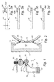
- the flexographic printer 1 shown diagrammatically in Figure 1 in a side view is provided with an inking blade unit 3 with a blade holder 9 carrying two blades 5, 7 to be further described in connection with Figure 2 . Furthermore, the printer 1 has an anilox roller 15 constituted by a steel drum covered with a ceramic sleeve or shell.
- the inking blade unit 3 is associated with a printing ink container 27, an ink feeding conduit 29 containing an ink feeding pump 31 for the transfer of printing ink from an ink supply 37 to the inking blade unit 3.
- a return conduit 35 is provided for the return of excessive printing ink to the container 27.
- the printer 1 is furthermore provided with a printing plate cylinder 21, carrying printing plates 19, and a pressure roller 23.
- a substrate 25, such as a paper web or a polymer film, for printing travels in the nip between cylinder 21 and roller 23 in the direction indicated in Figure 1 .
- FIG 2 there is shown by an enlarged side view the arrangement around the inking blade unit 3 as contained within the dashed line square of Figure 1 .
- the blade holder 9 is provided with two carrier flanges 11, 13, each carrying a blade 5, 7 arranged in butting and trailing positions, respectively, vis-a-vis the anilox roller 15.
- the anilox roller 15 is comprised of a steel cylinder 15 covered by a ceramic shell or sleeve 17, comprising Cr 2 O 3 as a main component.
- blade 7 has a sealing function
- blade 5 has a wiping function removing excess printing ink from the surface of the ceramic sleeve 17.
- the inking blade unit 3 defines an inking chamber 10 together with the anilox roller 15 with blades 5, 7 in engagement on the surface of the anilox roller 15.
- Blades 5, 7 are each provided with a coating 43, comprising a metal matrix and at least 65 wt% of a ceramic, facing the surface of the anilox roller 15.
- Figure 3a shows in a side view a steel strip 41 having an edge region 45 coated with a coating 43a comprising a metal matrix and at least 65 wt% of a ceramic.
- Figure 3a furthermore illustrates schematically the thickness t and the width w of the base element as referred to herein.
- Figure 3a also illustrates schematically the thickness ct and width cw of the coating as referred to herein.
- Figure 3b shows a similar arrangement but with the coating 43b being provided with a rounding 44 at the longitudinal region of the doctor blade adapted for contact with the anilox roller 15.
- Figure 3c shows an embodiment with the steel strip 41 being provided with a bevel 45c on the edge region, the coating 43c having a corresponding triangular configuration.
- the coating 43c has as well as a rounding 44 at the longitudinal region of the doctor blade adapted for contact with the anilox roller 15.
- Figure 3d shows an embodiment of the lamella type, wherein the strip edge region 45d has a recess opposite to the coating 43d.
- the coating 43d is shown with a square shape, but may alternatively have a rounded shape, at the longitudinal region of the doctor blade adapted for contact with the anilox roller 15.
- a fixed pin coated by thermal spraying with the respective materials listed in the tables was loaded against rotating discs of cast iron.
- Cast iron was selected to represent an appropriate counter surface in order to accelerate the wear process to be evaluated.
- the wear of the pin coating was calculated as the mass loss divided by the sliding distance and the load, and was reported as the pin wear coefficient.
- the wear of discs was measured as the depth of the wear track, and was reported as the disc wear depth.
- the pin and disc temperatures were measured.
- the friction force was calculated as end of test average.
- Doctor blades were manufactured by providing steel strips with coatings comprising CrC in a NiCr matrix by thermal spraying. CrC-Ni-Cr 80/17/3 wt% powders having different CrC particle size (about 5 ⁇ m and about 3.5 ⁇ m, particle size distribution average, Fisher Sub Sieve Sizer (FSSS) standard) were used as raw materials for the thermal spraying. Doctor blades having CrC-Ni-Cr coatings of different Vickers hardness (1050 Hv and 900 Hv) were obtained. The doctor blades were tested during 138 hours of operation on a full-scale flexographic printer with the following conditions and parameters.
- FSSS Fisher Sub Sieve Sizer
- Doctor blades were manufactured by providing steel strips with coatings comprising CrC in a NiCr matrix by thermal spraying.
- a CrC-Ni-Cr 80/17/3 wt% powder was used as raw material for the thermal spraying.
- the coatings formed were ground to obtain top and front surfaces meeting at an angle of about 90°, and subsequently polished to obtain a rounded shape of 30 ⁇ m diameter at the edge of the doctor blade intended for contact with the anilox roller.
- the doctor blades were tested on a full-scale flexographic printer with the following conditions and parameters.
- the main objective of this test was to investigate the influence of the blade tip design on the doctoring effectiveness and quality in order to optimize the ink dynamics management.
- a good printing result at least as good as for a reference lamella type steel blade having a front angle for adaptation to the anilox roller, was achieved with the rounded edge carbide based doctor blades.
- FIGS 4a and 4b are SEM images of the tip of doctor blades that have been used against an anilox roller.
- the blade top (outside the ink chamber) is denoted by T
- the sliding surface (in contact with the anilox roller surface) is denoted by S
- the blade front (inside the ink chamber) is denoted by F.
- Figure 4a is an image of the tip of a doctor blade having an Al 2 O 3 -ZrO 2 coating comprising 60 wt% Al 2 O 3 and 40 wt% ZrO 2 .
- Endcircled on the right is a local defect having a size of about 40 ⁇ m.
- Encircled on the left is a smaller defect extending all through the sliding surface, leading to a potential continuous leak of ink.
- These kinds of defects are common in such ceramic material.
- Especially defects of the type on the right may be even larger.
- this doctor blade has a narrow sliding surface because it was prematurely removed from a printing unit due to a quality issue.
- Figure 4b is an image of the tip of a doctor blade from Example 2 (CrC-Ni-Cr 80/17/3 wt%, CrC particle size about 5 ⁇ m (FSSS)). Encircled is a local defect having a size of no more than about 15 ⁇ m. This defect is the largest found in the analyses of worn blades from the full-scale tests of Example 2. The sliding surface is much wider than in Figure 4a , indicating that this doctor blade has been in operation in the printing unit for a long time without any quality issue.
Landscapes
- Engineering & Computer Science (AREA)
- Mechanical Engineering (AREA)
- Inking, Control Or Cleaning Of Printing Machines (AREA)
- Rotary Presses (AREA)
- Coating Apparatus (AREA)
Priority Applications (21)
| Application Number | Priority Date | Filing Date | Title |
|---|---|---|---|
| EP15192936.1A EP3165367A1 (de) | 2015-11-04 | 2015-11-04 | Rakel, farbwerkanordnung und verwendung der rakel beim flexodruck |
| PCT/EP2016/076697 WO2017077053A1 (en) | 2015-11-04 | 2016-11-04 | Doctor blade, inking arrangement and use of doctor blade in flexographic printing |
| CA3003223A CA3003223A1 (en) | 2015-11-04 | 2016-11-04 | Doctor blades, inking arrangement and use of doctor blade in flexographic printing |
| CN201680064783.7A CN108349241B (zh) | 2015-11-04 | 2016-11-04 | 刮刀片、上墨装置和刮刀片在柔性版印刷中的用途 |
| ES16793830T ES2779583T3 (es) | 2015-11-04 | 2016-11-04 | Rasqueta, disposición de entintado y utilización de una rasqueta en impresión flexográfica |
| EP16793830.7A EP3370971B1 (de) | 2015-11-04 | 2016-11-04 | Rakel, farbwerkanordnung und verwendung der rakel beim flexodruck |
| US15/773,428 US20180319156A1 (en) | 2015-11-04 | 2016-11-04 | Doctor blades, inking arrangement and use of doctor blade in flexographic printing |
| CA3003224A CA3003224C (en) | 2015-11-04 | 2016-11-04 | Doctor blade, inking arrangement and use of doctor blade in flexographic printing |
| PT167938307T PT3370971T (pt) | 2015-11-04 | 2016-11-04 | Lâmina raspadora, disposição da tinta e utilização da lâmina raspadora em impressão flexográfica |
| JP2018521958A JP2018532622A (ja) | 2015-11-04 | 2016-11-04 | ドクターブレード、インク装置、およびフレキソ印刷におけるドクターブレードの使用 |
| JP2018521947A JP6891171B2 (ja) | 2015-11-04 | 2016-11-04 | ドクターブレード、インク装置、およびフレキソ印刷におけるドクターブレードの使用 |
| BR112018009157A BR112018009157A8 (pt) | 2015-11-04 | 2016-11-04 | lâminas raspadoras, disposição de aplicação de tinta e uso de lâmina raspadora em impressão flexográfica |
| DK16793830.7T DK3370971T3 (da) | 2015-11-04 | 2016-11-04 | Afstryger, indfarvningsarrangement og anvendelse af afstryger i flexografisk trykning |
| EP16793827.3A EP3370970B1 (de) | 2015-11-04 | 2016-11-04 | Rakel, farbwerkanordnung und verwendung der rakel beim flexodruck |
| DK16793827.3T DK3370970T3 (da) | 2015-11-04 | 2016-11-04 | Afstrygere, indfarvningsarragement og anvendelse af afstryger i flexografisk trykning |
| ES16793827T ES2779466T3 (es) | 2015-11-04 | 2016-11-04 | Rasquetas, disposición de entintado y utilización de una rasqueta en impresión flexográfica |
| BR112018009154-5A BR112018009154B1 (pt) | 2015-11-04 | 2016-11-04 | Lâmina raspadora, disposição de aplicação de tinta e uso de lâmina raspadora |
| US15/773,437 US11718088B2 (en) | 2015-11-04 | 2016-11-04 | Doctor blade, inking arrangement and use of doctor blade in flexographic printing |
| PT167938273T PT3370970T (pt) | 2015-11-04 | 2016-11-04 | Lâminas raspadoras, disposição da tinta e utilização da lâmina raspadora em impressão flexográfica |
| CN201680064659.0A CN108349240A (zh) | 2015-11-04 | 2016-11-04 | 刮刀片、上墨装置和刮刀片在柔性版印刷中的用途 |
| PCT/EP2016/076692 WO2017077048A1 (en) | 2015-11-04 | 2016-11-04 | Doctor blades, inking arrangement and use of doctor blade in flexographic printing |
Applications Claiming Priority (1)
| Application Number | Priority Date | Filing Date | Title |
|---|---|---|---|
| EP15192936.1A EP3165367A1 (de) | 2015-11-04 | 2015-11-04 | Rakel, farbwerkanordnung und verwendung der rakel beim flexodruck |
Publications (1)
| Publication Number | Publication Date |
|---|---|
| EP3165367A1 true EP3165367A1 (de) | 2017-05-10 |
Family
ID=54366122
Family Applications (3)
| Application Number | Title | Priority Date | Filing Date |
|---|---|---|---|
| EP15192936.1A Withdrawn EP3165367A1 (de) | 2015-11-04 | 2015-11-04 | Rakel, farbwerkanordnung und verwendung der rakel beim flexodruck |
| EP16793830.7A Active EP3370971B1 (de) | 2015-11-04 | 2016-11-04 | Rakel, farbwerkanordnung und verwendung der rakel beim flexodruck |
| EP16793827.3A Active EP3370970B1 (de) | 2015-11-04 | 2016-11-04 | Rakel, farbwerkanordnung und verwendung der rakel beim flexodruck |
Family Applications After (2)
| Application Number | Title | Priority Date | Filing Date |
|---|---|---|---|
| EP16793830.7A Active EP3370971B1 (de) | 2015-11-04 | 2016-11-04 | Rakel, farbwerkanordnung und verwendung der rakel beim flexodruck |
| EP16793827.3A Active EP3370970B1 (de) | 2015-11-04 | 2016-11-04 | Rakel, farbwerkanordnung und verwendung der rakel beim flexodruck |
Country Status (10)
| Country | Link |
|---|---|
| US (2) | US11718088B2 (de) |
| EP (3) | EP3165367A1 (de) |
| JP (2) | JP2018532622A (de) |
| CN (2) | CN108349240A (de) |
| BR (2) | BR112018009157A8 (de) |
| CA (2) | CA3003223A1 (de) |
| DK (2) | DK3370970T3 (de) |
| ES (2) | ES2779466T3 (de) |
| PT (2) | PT3370970T (de) |
| WO (2) | WO2017077053A1 (de) |
Cited By (1)
| Publication number | Priority date | Publication date | Assignee | Title |
|---|---|---|---|---|
| WO2024149481A1 (de) * | 2023-01-11 | 2024-07-18 | Clouth Sprenger Gmbh | Schaberklinge mit abgerundeter kontaktspitze |
Families Citing this family (2)
| Publication number | Priority date | Publication date | Assignee | Title |
|---|---|---|---|---|
| GB2582635B (en) * | 2019-03-28 | 2021-12-29 | Archipelago Tech Group Ltd | Device, method, and assembly for loading nozzles with fluid |
| EP3912817A1 (de) * | 2020-05-19 | 2021-11-24 | Daetwyler Swisstec Ag | Ablängbares rakelband für die drucktechnik |
Citations (5)
| Publication number | Priority date | Publication date | Assignee | Title |
|---|---|---|---|---|
| DE4024514A1 (de) * | 1990-08-02 | 1992-02-06 | Marina Kinkel | Rakeln fuer druckmaschinen |
| WO2001060620A1 (en) | 2000-01-25 | 2001-08-23 | Btg Eclepens S.A. | Doctor blade |
| WO2007003332A1 (en) * | 2005-07-01 | 2007-01-11 | BTG Eclépens S.A. | Improved coating blade |
| DE102008001721A1 (de) * | 2008-05-13 | 2009-11-19 | Voith Patent Gmbh | Verfahren zum Beschichten einer Klinge |
| US20130014656A1 (en) | 2010-01-20 | 2013-01-17 | Daetwyler Swisstec Ag | Doctor blade |
Family Cites Families (17)
| Publication number | Priority date | Publication date | Assignee | Title |
|---|---|---|---|---|
| DE3110842A1 (de) | 1981-03-20 | 1982-09-30 | Basf Ag, 6700 Ludwigshafen | Rakel fuer den tiefdruck mit kunststoff-druckschichten |
| DE3302317A1 (de) | 1982-01-29 | 1983-08-11 | M.A.N.- Roland Druckmaschinen AG, 6050 Offenbach | Farbdosierelement, insbesondere farbmesser oder farbschieber, fuer das farbwerk einer rotationsdruckmaschine |
| SE511082C2 (sv) * | 1996-12-20 | 1999-08-02 | Btg Eclepens Sa | Beläggningsblad |
| US6155167A (en) | 1999-01-21 | 2000-12-05 | Meyer; Rolf | Printing doctor with a coating of hard material and method for producing same |
| JP3620713B2 (ja) * | 2000-12-07 | 2005-02-16 | 日本ニュークローム株式会社 | ドクターブレード及びその製造方法 |
| JP4375652B2 (ja) | 2002-11-21 | 2009-12-02 | 日本ニュークローム株式会社 | ドクターブレード |
| DE102004034905A1 (de) | 2004-07-19 | 2006-04-13 | Böhler-Uddeholm Precision Strip GmbH & Co. KG | Stahlband für Streichmesser, Auftragsmesser und Kreppschaber und pulvermetallurgisches Verfahren zu ihrer Herstellung |
| CA2600479A1 (en) * | 2005-07-22 | 2007-02-01 | Tdy Industries, Inc. | Composite materials |
| CN100387775C (zh) * | 2006-04-13 | 2008-05-14 | 山东科技大学 | 耐磨型造纸涂布刮刀 |
| US7691236B2 (en) * | 2006-07-26 | 2010-04-06 | The Procter + Gamble Company | Creping blade with a highly smooth bevel surface |
| DE602006002039D1 (de) * | 2006-12-04 | 2008-09-11 | C B G Acciai S R L | Vorgehonte Rakel mit bogenförmigem Lamellenprofil und Herstellungsverfahren für die Rakel |
| JP5029238B2 (ja) * | 2007-09-11 | 2012-09-19 | 凸版印刷株式会社 | 有機エレクトロルミネッセンス素子の製造方法 |
| DE102009029697A1 (de) * | 2009-09-23 | 2011-03-24 | Voith Patent Gmbh | Spritzpulver zur Cermet-Beschichtung von Rakelklingen |
| SE535064C2 (sv) | 2010-08-23 | 2012-04-03 | Sandvik Intellectual Property | Kallvalsad och härdad bandstålsprodukt |
| WO2012128700A1 (en) | 2011-03-18 | 2012-09-27 | Allan Lunnerfjord | Blade shaped tool and method for its manufacturing |
| WO2013133762A1 (en) * | 2012-03-08 | 2013-09-12 | Swedev Ab | Electrolytically puls-plated doctor blade with a multiple layer coating |
| CN103481661A (zh) * | 2013-09-05 | 2014-01-01 | 常熟市董浜镇徐市嘉峰机械厂 | 一种油墨刮刀结构 |
-
2015
- 2015-11-04 EP EP15192936.1A patent/EP3165367A1/de not_active Withdrawn
-
2016
- 2016-11-04 DK DK16793827.3T patent/DK3370970T3/da active
- 2016-11-04 ES ES16793827T patent/ES2779466T3/es active Active
- 2016-11-04 ES ES16793830T patent/ES2779583T3/es active Active
- 2016-11-04 US US15/773,437 patent/US11718088B2/en active Active
- 2016-11-04 CN CN201680064659.0A patent/CN108349240A/zh active Pending
- 2016-11-04 PT PT167938273T patent/PT3370970T/pt unknown
- 2016-11-04 EP EP16793830.7A patent/EP3370971B1/de active Active
- 2016-11-04 US US15/773,428 patent/US20180319156A1/en not_active Abandoned
- 2016-11-04 BR BR112018009157A patent/BR112018009157A8/pt not_active Application Discontinuation
- 2016-11-04 JP JP2018521958A patent/JP2018532622A/ja not_active Ceased
- 2016-11-04 CA CA3003223A patent/CA3003223A1/en not_active Abandoned
- 2016-11-04 CA CA3003224A patent/CA3003224C/en active Active
- 2016-11-04 CN CN201680064783.7A patent/CN108349241B/zh active Active
- 2016-11-04 PT PT167938307T patent/PT3370971T/pt unknown
- 2016-11-04 WO PCT/EP2016/076697 patent/WO2017077053A1/en not_active Ceased
- 2016-11-04 EP EP16793827.3A patent/EP3370970B1/de active Active
- 2016-11-04 BR BR112018009154-5A patent/BR112018009154B1/pt active IP Right Grant
- 2016-11-04 WO PCT/EP2016/076692 patent/WO2017077048A1/en not_active Ceased
- 2016-11-04 JP JP2018521947A patent/JP6891171B2/ja active Active
- 2016-11-04 DK DK16793830.7T patent/DK3370971T3/da active
Patent Citations (5)
| Publication number | Priority date | Publication date | Assignee | Title |
|---|---|---|---|---|
| DE4024514A1 (de) * | 1990-08-02 | 1992-02-06 | Marina Kinkel | Rakeln fuer druckmaschinen |
| WO2001060620A1 (en) | 2000-01-25 | 2001-08-23 | Btg Eclepens S.A. | Doctor blade |
| WO2007003332A1 (en) * | 2005-07-01 | 2007-01-11 | BTG Eclépens S.A. | Improved coating blade |
| DE102008001721A1 (de) * | 2008-05-13 | 2009-11-19 | Voith Patent Gmbh | Verfahren zum Beschichten einer Klinge |
| US20130014656A1 (en) | 2010-01-20 | 2013-01-17 | Daetwyler Swisstec Ag | Doctor blade |
Cited By (1)
| Publication number | Priority date | Publication date | Assignee | Title |
|---|---|---|---|---|
| WO2024149481A1 (de) * | 2023-01-11 | 2024-07-18 | Clouth Sprenger Gmbh | Schaberklinge mit abgerundeter kontaktspitze |
Also Published As
| Publication number | Publication date |
|---|---|
| CA3003224A1 (en) | 2017-05-11 |
| EP3370971B1 (de) | 2019-12-25 |
| BR112018009154A2 (pt) | 2018-11-06 |
| WO2017077048A1 (en) | 2017-05-11 |
| ES2779583T3 (es) | 2020-08-18 |
| BR112018009154A8 (pt) | 2019-02-26 |
| CN108349240A (zh) | 2018-07-31 |
| CN108349241A (zh) | 2018-07-31 |
| PT3370971T (pt) | 2020-03-27 |
| CA3003223A1 (en) | 2017-05-11 |
| EP3370971A1 (de) | 2018-09-12 |
| BR112018009157A2 (pt) | 2018-11-06 |
| WO2017077053A1 (en) | 2017-05-11 |
| DK3370971T3 (da) | 2020-03-23 |
| US20180319153A1 (en) | 2018-11-08 |
| JP6891171B2 (ja) | 2021-06-18 |
| CN108349241B (zh) | 2021-09-10 |
| BR112018009157A8 (pt) | 2019-02-26 |
| EP3370970A1 (de) | 2018-09-12 |
| EP3370970B1 (de) | 2019-12-25 |
| ES2779466T3 (es) | 2020-08-17 |
| JP2018532621A (ja) | 2018-11-08 |
| JP2018532622A (ja) | 2018-11-08 |
| BR112018009154B1 (pt) | 2023-12-26 |
| PT3370970T (pt) | 2020-03-27 |
| DK3370970T3 (da) | 2020-03-23 |
| US20180319156A1 (en) | 2018-11-08 |
| CA3003224C (en) | 2022-09-13 |
| US11718088B2 (en) | 2023-08-08 |
Similar Documents
| Publication | Publication Date | Title |
|---|---|---|
| EP1163113B1 (de) | Rakelblatt | |
| EP3370970B1 (de) | Rakel, farbwerkanordnung und verwendung der rakel beim flexodruck | |
| JP2010240897A (ja) | グラビアコーティング用ドクター | |
| US20110226144A1 (en) | Diamond-coated doctor blade | |
| CN102666904A (zh) | 用于刮刀的金属陶瓷涂层的喷粉 | |
| EP0262137B1 (de) | Verschleissfester rakel | |
| GB2089473A (en) | Ink Ductor Roller | |
| KR20140037365A (ko) | 초고속 용사방식을 이용한 그라비어 인쇄 롤의 제조방법 및 그라비어 인쇄 롤 | |
| CN201979788U (zh) | 一种氮化钛金属涂层油墨刮刀 | |
| US9044927B2 (en) | Doctor blade | |
| KR20170092687A (ko) | 수명이 긴 서멧 코팅된 크레이핑 블레이드 | |
| EP3023512A1 (de) | Modifizierte Wolframcarbidbeschichtung für Rakelkingenoberflächen zur Minimierung von Defekten in der Papierherstellung | |
| DE102005062204A1 (de) | Verschleißschutzbeschichtung | |
| SE516371C2 (en) | Doctor blade for inking system of e.g., flexographic printer, has ceramic coating provided on strip of metallic carrier | |
| DE8717972U1 (de) | Farbübertragungswalze mit abriebfester Beschichtung | |
| KR20050092858A (ko) | 코터 블레이드의 제조 방법 및 이에 따른 코터 블레이드 | |
| JPS6311341A (ja) | 平版印刷用メツシユロ−ル |
Legal Events
| Date | Code | Title | Description |
|---|---|---|---|
| PUAI | Public reference made under article 153(3) epc to a published international application that has entered the european phase |
Free format text: ORIGINAL CODE: 0009012 |
|
| STAA | Information on the status of an ep patent application or granted ep patent |
Free format text: STATUS: THE APPLICATION HAS BEEN PUBLISHED |
|
| AK | Designated contracting states |
Kind code of ref document: A1 Designated state(s): AL AT BE BG CH CY CZ DE DK EE ES FI FR GB GR HR HU IE IS IT LI LT LU LV MC MK MT NL NO PL PT RO RS SE SI SK SM TR |
|
| AX | Request for extension of the european patent |
Extension state: BA ME |
|
| STAA | Information on the status of an ep patent application or granted ep patent |
Free format text: STATUS: THE APPLICATION IS DEEMED TO BE WITHDRAWN |
|
| 18D | Application deemed to be withdrawn |
Effective date: 20171111 |