EP3163003B1 - Wasserdichte schwingtor-vorrichtung - Google Patents
Wasserdichte schwingtor-vorrichtung Download PDFInfo
- Publication number
- EP3163003B1 EP3163003B1 EP16195978.8A EP16195978A EP3163003B1 EP 3163003 B1 EP3163003 B1 EP 3163003B1 EP 16195978 A EP16195978 A EP 16195978A EP 3163003 B1 EP3163003 B1 EP 3163003B1
- Authority
- EP
- European Patent Office
- Prior art keywords
- door
- frame
- door leaf
- leaf
- spindle
- Prior art date
- Legal status (The legal status is an assumption and is not a legal conclusion. Google has not performed a legal analysis and makes no representation as to the accuracy of the status listed.)
- Active
Links
Images


Classifications
-
- E—FIXED CONSTRUCTIONS
- E06—DOORS, WINDOWS, SHUTTERS, OR ROLLER BLINDS IN GENERAL; LADDERS
- E06B—FIXED OR MOVABLE CLOSURES FOR OPENINGS IN BUILDINGS, VEHICLES, FENCES OR LIKE ENCLOSURES IN GENERAL, e.g. DOORS, WINDOWS, BLINDS, GATES
- E06B9/00—Screening or protective devices for wall or similar openings, with or without operating or securing mechanisms; Closures of similar construction
- E06B9/02—Shutters, movable grilles, or other safety closing devices, e.g. against burglary
- E06B9/04—Shutters, movable grilles, or other safety closing devices, e.g. against burglary of wing type, e.g. revolving or sliding
-
- E—FIXED CONSTRUCTIONS
- E05—LOCKS; KEYS; WINDOW OR DOOR FITTINGS; SAFES
- E05D—HINGES OR SUSPENSION DEVICES FOR DOORS, WINDOWS OR WINGS
- E05D15/00—Suspension arrangements for wings
- E05D15/40—Suspension arrangements for wings supported on arms movable in vertical planes
- E05D15/401—Suspension arrangements for wings supported on arms movable in vertical planes specially adapted for overhead wings
-
- E—FIXED CONSTRUCTIONS
- E05—LOCKS; KEYS; WINDOW OR DOOR FITTINGS; SAFES
- E05D—HINGES OR SUSPENSION DEVICES FOR DOORS, WINDOWS OR WINGS
- E05D15/00—Suspension arrangements for wings
- E05D15/40—Suspension arrangements for wings supported on arms movable in vertical planes
- E05D15/403—Suspension arrangements for wings supported on arms movable in vertical planes with arms fixed on the wing pivoting about an axis outside the wing
-
- E—FIXED CONSTRUCTIONS
- E06—DOORS, WINDOWS, SHUTTERS, OR ROLLER BLINDS IN GENERAL; LADDERS
- E06B—FIXED OR MOVABLE CLOSURES FOR OPENINGS IN BUILDINGS, VEHICLES, FENCES OR LIKE ENCLOSURES IN GENERAL, e.g. DOORS, WINDOWS, BLINDS, GATES
- E06B1/00—Border constructions of openings in walls, floors, or ceilings; Frames to be rigidly mounted in such openings
- E06B1/04—Frames for doors, windows, or the like to be fixed in openings
- E06B1/52—Frames specially adapted for doors
- E06B1/522—Frames specially adapted for doors for overhead garage doors
-
- E—FIXED CONSTRUCTIONS
- E06—DOORS, WINDOWS, SHUTTERS, OR ROLLER BLINDS IN GENERAL; LADDERS
- E06B—FIXED OR MOVABLE CLOSURES FOR OPENINGS IN BUILDINGS, VEHICLES, FENCES OR LIKE ENCLOSURES IN GENERAL, e.g. DOORS, WINDOWS, BLINDS, GATES
- E06B3/00—Window sashes, door leaves, or like elements for closing wall or like openings; Layout of fixed or moving closures, e.g. windows in wall or like openings; Features of rigidly-mounted outer frames relating to the mounting of wing frames
- E06B3/70—Door leaves
- E06B3/72—Door leaves consisting of frame and panels, e.g. of raised panel type
-
- E—FIXED CONSTRUCTIONS
- E06—DOORS, WINDOWS, SHUTTERS, OR ROLLER BLINDS IN GENERAL; LADDERS
- E06B—FIXED OR MOVABLE CLOSURES FOR OPENINGS IN BUILDINGS, VEHICLES, FENCES OR LIKE ENCLOSURES IN GENERAL, e.g. DOORS, WINDOWS, BLINDS, GATES
- E06B7/00—Special arrangements or measures in connection with doors or windows
- E06B7/16—Sealing arrangements on wings or parts co-operating with the wings
- E06B7/18—Sealing arrangements on wings or parts co-operating with the wings by means of movable edgings, e.g. draught sealings additionally used for bolting, e.g. by spring force or with operating lever
-
- E—FIXED CONSTRUCTIONS
- E06—DOORS, WINDOWS, SHUTTERS, OR ROLLER BLINDS IN GENERAL; LADDERS
- E06B—FIXED OR MOVABLE CLOSURES FOR OPENINGS IN BUILDINGS, VEHICLES, FENCES OR LIKE ENCLOSURES IN GENERAL, e.g. DOORS, WINDOWS, BLINDS, GATES
- E06B7/00—Special arrangements or measures in connection with doors or windows
- E06B7/16—Sealing arrangements on wings or parts co-operating with the wings
- E06B7/22—Sealing arrangements on wings or parts co-operating with the wings by means of elastic edgings, e.g. elastic rubber tubes; by means of resilient edgings, e.g. felt or plush strips, resilient metal strips
- E06B7/23—Plastic, sponge rubber, or like strips or tubes
- E06B7/2301—Plastic, sponge rubber, or like strips or tubes without an integrally formed part for fixing the edging
- E06B7/2303—Plastic, sponge rubber, or like strips or tubes without an integrally formed part for fixing the edging hollow
-
- E—FIXED CONSTRUCTIONS
- E05—LOCKS; KEYS; WINDOW OR DOOR FITTINGS; SAFES
- E05D—HINGES OR SUSPENSION DEVICES FOR DOORS, WINDOWS OR WINGS
- E05D15/00—Suspension arrangements for wings
- E05D15/16—Suspension arrangements for wings for wings sliding vertically more or less in their own plane
- E05D15/165—Details, e.g. sliding or rolling guides
-
- E—FIXED CONSTRUCTIONS
- E05—LOCKS; KEYS; WINDOW OR DOOR FITTINGS; SAFES
- E05Y—INDEXING SCHEME ASSOCIATED WITH SUBCLASSES E05D AND E05F, RELATING TO CONSTRUCTION ELEMENTS, ELECTRIC CONTROL, POWER SUPPLY, POWER SIGNAL OR TRANSMISSION, USER INTERFACES, MOUNTING OR COUPLING, DETAILS, ACCESSORIES, AUXILIARY OPERATIONS NOT OTHERWISE PROVIDED FOR, APPLICATION THEREOF
- E05Y2201/00—Constructional elements; Accessories therefor
- E05Y2201/20—Brakes; Disengaging means; Holders; Stops; Valves; Accessories therefor
- E05Y2201/218—Holders
- E05Y2201/22—Locks
-
- E—FIXED CONSTRUCTIONS
- E05—LOCKS; KEYS; WINDOW OR DOOR FITTINGS; SAFES
- E05Y—INDEXING SCHEME ASSOCIATED WITH SUBCLASSES E05D AND E05F, RELATING TO CONSTRUCTION ELEMENTS, ELECTRIC CONTROL, POWER SUPPLY, POWER SIGNAL OR TRANSMISSION, USER INTERFACES, MOUNTING OR COUPLING, DETAILS, ACCESSORIES, AUXILIARY OPERATIONS NOT OTHERWISE PROVIDED FOR, APPLICATION THEREOF
- E05Y2800/00—Details, accessories and auxiliary operations not otherwise provided for
- E05Y2800/10—Additional functions
- E05Y2800/12—Sealing
-
- E—FIXED CONSTRUCTIONS
- E05—LOCKS; KEYS; WINDOW OR DOOR FITTINGS; SAFES
- E05Y—INDEXING SCHEME ASSOCIATED WITH SUBCLASSES E05D AND E05F, RELATING TO CONSTRUCTION ELEMENTS, ELECTRIC CONTROL, POWER SUPPLY, POWER SIGNAL OR TRANSMISSION, USER INTERFACES, MOUNTING OR COUPLING, DETAILS, ACCESSORIES, AUXILIARY OPERATIONS NOT OTHERWISE PROVIDED FOR, APPLICATION THEREOF
- E05Y2800/00—Details, accessories and auxiliary operations not otherwise provided for
- E05Y2800/40—Physical or chemical protection
- E05Y2800/428—Physical or chemical protection against water or ice
-
- E—FIXED CONSTRUCTIONS
- E05—LOCKS; KEYS; WINDOW OR DOOR FITTINGS; SAFES
- E05Y—INDEXING SCHEME ASSOCIATED WITH SUBCLASSES E05D AND E05F, RELATING TO CONSTRUCTION ELEMENTS, ELECTRIC CONTROL, POWER SUPPLY, POWER SIGNAL OR TRANSMISSION, USER INTERFACES, MOUNTING OR COUPLING, DETAILS, ACCESSORIES, AUXILIARY OPERATIONS NOT OTHERWISE PROVIDED FOR, APPLICATION THEREOF
- E05Y2900/00—Application of doors, windows, wings or fittings thereof
- E05Y2900/10—Application of doors, windows, wings or fittings thereof for buildings or parts thereof
- E05Y2900/106—Application of doors, windows, wings or fittings thereof for buildings or parts thereof for garages
-
- E—FIXED CONSTRUCTIONS
- E06—DOORS, WINDOWS, SHUTTERS, OR ROLLER BLINDS IN GENERAL; LADDERS
- E06B—FIXED OR MOVABLE CLOSURES FOR OPENINGS IN BUILDINGS, VEHICLES, FENCES OR LIKE ENCLOSURES IN GENERAL, e.g. DOORS, WINDOWS, BLINDS, GATES
- E06B3/00—Window sashes, door leaves, or like elements for closing wall or like openings; Layout of fixed or moving closures, e.g. windows in wall or like openings; Features of rigidly-mounted outer frames relating to the mounting of wing frames
- E06B3/70—Door leaves
- E06B2003/7044—Garage doors
Definitions
- the invention relates to a Schwingtor device with a pivotally mounted gate, which is reversibly pivotable by means of a driven means of a drive means pivoting device from a first position in which the gate is open, in a second position, in which the gate in the region of its outer edge adjacent to a two horizontal frame struts and two vertical frame struts having door frame and thereby closes the door frame, wherein in the closed state of the door facing a arranged in the lower region of the periphery of the door frame goal frame stop rail of a door leaf sealing strip.
- Gate devices of the type mentioned are in the art in very large numbers for a variety of Applications and in different versions known.
- the known gate devices usually have the disadvantage that they are not waterproof sealable.
- An overhead gate device having the features of the preamble of claim 1 is made EP 1 369 549 A known.
- Waterproof swing gate devices are off EP 2 607 600 A and US 3,440,762 A known.
- the object of the invention is therefore to develop the known gate devices so that at least in a ground-level, lower portion of the door, a watertight barrier at least against the ingress of rain, snow and sleet, preferably against ingress of flood, is generated.
- the waterproof version is applied directly by the force of the lower end of the reciprocally mounted mandrel in interaction with the goal frame stop rail.
- This very effective mechanism for pressing each other door leaf weatherstrip and Torrahmen stop rail acts in the gate device according to the invention additionally and independently of a built-up by cooperation of a pivot bearing with a lever element pressure of the door leaf sealing strip against the door frame stop rail.
- the mandrel is mounted vertically displaceable in a sealing position of the door leaf.
- the mandrel is preferably mounted reciprocally displaceable in a guide attached to the inner surface of the door leaf.
- the lower end of the mandrel is formed tapering, wherein the mandrel is mounted in the region of the inner surface of the gate so that the tip of the mandrel upon transfer of the mandrel in a sealing position for engaging behind the goal frame stop rail in the gate leaf inner surface of the Gate frame stop rail comes to rest.
- the tapered lower end of the mandrel has an edge running at an acute angle to the vertical, which during the Operation of transferring the mandrel in a sealing position, a lever effect on the wing with the gate leaf sealing strip exerts, by means of which a watertight seal between gate leaf sealing strip and Torrahmen stop rail can be generated.
- a manually operable rotating member is mounted, whose axis of rotation is aligned normal to the door leaf and provided with tooth elements, which cooperate with mounted in the upper region of the mandrel tooth elements to a rotation of the rotation member is a linear to effect vertical displacement of the mandrel.
- a recess for receiving the lower end of the located in sealing position mandrel may be provided.
- a fixation for a pivot bearing of the gate is provided in a respective central portion of the two vertical frame struts, and both fulcrum bearings each arranged with one in a respective central portion of a side wing portion of the gate Lever element cooperate, wherein in the region of parts of the outer edge of the door frame, a stop rail is provided which in the closed state of the door leaf to an arranged in the below the two lever elements outer peripheral regions of Outer surface of the door leaf arranged sealing strip adjacent, and wherein the lever elements in conjunction with the force of the drive device cause a watertight seal between stop rail and sealing strip.
- a pivot bearing is arranged outside the plane of the goal frame at a fixed predetermined distance from the plane of the goal frame.
- a corresponding fulcrum bearing is preferably arranged offset from the plane of the goal frame in the direction of the interior of the door to be protected from the plane of the goal frame out, according to the invention usually a distance of 3 cm to 30 cm between a pivot bearing and the plane of the goal frame is formed.
- a pivot bearing each having a cooperating with a lever member rotatably mounted disc, wherein the disc is preferably rotatably mounted about a horizontal axis, and wherein the axle bearing is fixedly connected via a support member with a respective vertical frame strut ,
- a lever element is designed as a vertically arranged panel, with an abutment surface which, when the door leaf closes, adjoins tangentially to the periphery of the rotatable disc.
- a corresponding panel may in particular be formed as part of a partially open cage.
- Such a cage is preferably designed to be open at the bottom for interaction between the disc and the interface of the panel provided inside the cage, so that insertion of the disc from below into the cage is possible, the cage also containing a support panel that the cage is fixedly connected to a wing wing designed as a lateral wing part of the gate.
- the lateral wing struts of the door leaf above the lever elements are at least indirectly connected to rollers rotatably mounted about a horizontal axis, wherein the rollers are guided in respective guide rails, reversible to the gate by means of the drive means a horizontal position in which the door frame is opened, to promote in a vertical position in which the door frame is closed, wherein the side wing struts of the gate are aligned parallel to the vertical frame struts of the goal frame.
- the pivoting device preferably includes two each pivotable about a horizontal axis bearing lever arms, wherein the lateral wing struts of the leaf below the lever elements are each at least indirectly connected to a rotatably mounted end of a corresponding, in the region of its other end about a horizontal axis bearing pivotable lever arm , and wherein a respective axle bearing is fixed to a respective vertical frame strut below a fixation for a pivot bearing of the gate.
- the in the FIGS. 1 to 4 illustrated Schwingtor device 100 includes a pivotally mounted gate 110, which is reversibly pivotable by means of a drive means pivoting means from a first position in which the door leaf 110 is opened in a second position in which the door leaf 110 in the area its outer edge adjacent to a two horizontal frame struts 121 and two vertical frame struts 122 having door frame 120 and thereby closes the door frame 120, wherein in the closed state of the door leaf in the lower one Area of the periphery of the door frame arranged goal frame stop rail 123 of a door leaf sealing strip 124 faces.
- mandrel 190 In the region of the inner surface of the door leaf 110 at least one perpendicular to the surface normal of the door leaf 110 slidably mounted mandrel 190 is mounted, which is convertible from a neutral position in which a lower end of the mandrel 190 is free, in a sealing position in which the lower end of the mandrel 190 engages behind a door frame stop rail 123 close to the floor, in order to press the door leaf sealing strip 124 against the door frame stop rail 123 with the gate leaf for the purpose of a watertight closure between gate leaf sealing strip 124 and gate frame stop rail 123.
- the mandrel 190 is arranged in a fixed to the inner surface of the door leaf 110 guide 112 so that it is mounted vertically reciprocally displaceable in the sealing position of the door leaf 110.
- the lower end of the mandrel 190 is formed tapered, wherein the mandrel 190 is mounted in the region of the inner surface of the door leaf 110 so that the tip of the mandrel 190 in transferring the mandrel 190 in a sealing position for engaging behind the goal frame stop rail 123 in the area the door leaf 110 far inner surface of the door frame stop rail 123 comes to rest.
- the tapered lower end of the mandrel 190 has a flank 191 at an acute angle to the longitudinal axis of the mandrel 190, which during the process of transferring the Dorns 190 in a sealing position by a contact with the door frame stop rail 123, a lever effect on the associated with the door leaf 110 door leaf sealing strip 124 which creates a watertight seal between gate leaf sealing strip 124 and Torrahmen stop rail 123.
- a manually operable rotary member 195 is mounted, whose axis of rotation is aligned normal to the door leaf 110 and provided with tooth elements which cooperate with mounted in the upper region of the mandrel 190 tooth elements to rotate about a rotation of the element 195 to effect a linear vertical displacement of the mandrel 190.
- a recess 196 for receiving the lower end of the sealing position located in the mandrel 190 is provided.
- a fixing for a fulcrum bearing 130 of the door leaf 110 is provided in a respective middle section of the two vertical frame struts 122, wherein both fulcrum bearings 130 are each arranged with a lateral wing part 110 of the door leaf 110 formed in each middle section of a wing strut 111 Lever element 140 interact.
- a stop rail 123 is provided, which in the closed state of the door leaf 110 to one in the below the two sealing elements 140 disposed outer peripheral regions of the outer surface of the door leaf 110 arranged sealing strip 124 adjacent.
- the lever elements 140 in conjunction with the force of the drive device cause a watertight closure between stop rail 123 and sealing strip 124.
- a respective fulcrum bearing 130 is arranged offset from the plane of the door frame 120 in the direction of the interior to be protected by the door leaf 110 out of the plane of the door frame 120, wherein the distance to the plane of the door frame 120 is 5 cm.
- a respective fulcrum bearing 130 each includes a cooperating with a lever member 140, about a horizontal axis 131 rotatably mounted disc 132, wherein the relevant axle bearing is fixedly connected via a support member 150 with a respective vertical frame strut 122.
- a lever element 140 is designed as a vertically arranged panel which is provided with an abutment surface 141 which, when the door leaf 110 is closed, tangentially adjoins the periphery of the rotatable disc 132.
- a panel 140 is formed as part of a partially open cage 133.
- Such a cage 133 is formed for an interaction between the disc 132 and provided in the interior of the cage 133
- Anlag Chemistry 141 of the panel 140 downwardly open and further firmly connected via a support panel 134 with the formed as a wing struts 111 side wing portion of the gate 110.
- the lateral wing struts 111 of the door leaf 110 are above the lever elements 140 at least indirectly connected to a horizontal axis rotatably mounted rollers 160, the rollers 160 are guided in respective guide rails 170 to the door leaf 110 by means of the drive means reversible from a horizontal position, in the door frame 120 is opened to promote to a vertical position in which the door frame 120 is closed, wherein the side wing struts 111 of the door leaf 110 are aligned parallel to the vertical frame struts 122 of the door frame 120.
- the pivoting device comprises two lever arms 180 each pivotable about a horizontal axis bearing, the lateral wing struts 111 of the door leaf 110 below the lever elements 140 each being at least indirectly connected to a rotatably mounted end 181 of a corresponding axis, in the region of its other end 183 about a horizontal axis.
- Bearing 182 pivotable lever arm 180 are connected, and wherein a respective axle bearing 182 is attached to a respective vertical frame strut 122 below a fixation for a pivot bearing 130 of the door leaf 110.
Landscapes
- Engineering & Computer Science (AREA)
- Structural Engineering (AREA)
- Civil Engineering (AREA)
- Architecture (AREA)
- Mechanical Engineering (AREA)
- Barrages (AREA)
Description
- Die Erfindung betrifft eine Schwingtor-Vorrichtung mit einem schwenkbar gelagerten Torflügel, der mit Hilfe einer mittels einer Antriebseinrichtung betreibbaren Schwenkeinrichtung reversibel aus einer ersten Position, in der der Torflügel geöffnet ist, in eine zweite Position verschwenkbar ist, in welcher der Torflügel im Bereich seiner Außenkante an einen zwei horizontale Rahmenstreben und zwei vertikale Rahmenstreben aufweisenden Torrahmen angrenzt und den Torrahmen dadurch verschließt, wobei in verschlossenem Zustand des Torflügels eine im unteren Bereich der Peripherie des Torrahmens angeordnete Torrahmen-Anschlagschiene einer Torflügel-Dichtungsleiste gegenübersteht.
- Tor-Vorrichtungen der eingangs genannten Art sind im Stand der Technik in sehr großer Zahl für verschiedenste Anwendungen und in unterschiedlichen Ausführungen bekannt. Die bekannten Tor-Vorrichtungen weisen indes in der Regel den Nachteil auf, dass sie nicht wasserdicht verschließbar sind.
- Eine Schwingtor-Vorrichtung mit dem Merkmalen des Oberbegriffs des Anspruchs 1 ist aus
EP 1 369 549 A bekannt. - Wasserdichte Schwingtor-Vorrichtungen sind aus
EP 2 607 600 A undUS 3 440 762 A bekannt. - Aufgabe der Erfindung ist es deshalb, die bekannten Tor-Vorrichtungen so weiterzubilden, dass zumindest in einem bodennahen, unteren Abschnitt des Tores eine wasserdichte Barriere zumindest gegen ein Eindringen von Regen, Schnee und Graupel, vorzugsweise auch gegen ein Eindringen von Hochwasser, erzeugt wird.
- Für eine Tor-Vorrichtung der eingangs genannten Art wird diese Aufgabe erfindungsgemäß durch eine Schwingtor-Vorrichtung mit den Merkmalen des Anspruchs 1 gelöst. Bevorzugte Ausführungsformen der Erfindung sind Gegenstand der Unteransprüche.
- Bei der erfindungsgemäßen Tor-Vorrichtung wird durch die Merkmalskombination des Patentanspruchs 1 eine zeitlich unbeschränkte wasserdichte Ausführung eines um eine horizontale Achse verschwenkbaren Torflügels zumindest eines bodennahen, unteren Bereiches eines Schwenktores realisiert. Die wasserdichte Ausführung wird dabei direkt durch die Krafteinwirkung des unteren Endes des reziprozierbar gelagerten Dornes im Zusammenspiel mit der Torrahmen-Anschlagschiene aufgebracht.
- Dieser sehr effektive Mechanismus zum respektiven Aneinanderdrücken von Torflügel-Dichtungsleiste und Torrahmen-Anschlagschiene wirkt bei der erfindungsgemäßen Tor-Vorrichtung zusätzlich und unabhängig von einem durch Zusammenwirken von einem Drehpunkt-Lager mit einem Hebelelement aufgebauten Druck der Torflügel-Dichtungsleiste gegen die Torrahmen-Anschlagschiene.
- Gemäß einer ersten bevorzugten Ausführungsform der erfindungsgemäßen Vorrichtung ist der Dorn in einer Dichtungsposition des Torflügels vertikal verschiebbar gelagert. Der Dorn ist dabei vorzugsweise in einer an der Innenfläche des Torflügels befestigten Führung reziprozierbar verschiebbar gelagert.
- Das untere Ende des Dorns ist spitz zulaufend ausgebildet, wobei der Dorn im Bereich der Innenfläche des Torflügels so gelagert ist, dass die Spitze des Dorns bei Überführen des Dorns in eine Dichtungsposition für ein Hintergreifen der Torrahmen-Anschlagschiene im Bereich der dem Torflügel fernen Innenfläche der Torrahmen-Anschlagschiene zu liegen kommt.
- Gemäß einer wichtigen bevorzugten Ausführungsform der erfindungsgemäßen Vorrichtung weist das spitz zulaufende untere Ende des Dorns eine im spitzen Winkel zur Senkrechten verlaufende Flanke auf, die während des Vorgangs des Überführen des Dorns in eine Dichtungsposition eine Hebelwirkung auf die mit dem Torflügel die Torflügel-Dichtungsleiste ausübt, mittels derer ein wasserdichter Abschluss zwischen Torflügel-Dichtungsleiste und Torrahmen-Anschlagschiene erzeugbar ist.
- Des Weiteren ist vorzugsweise im Bereich der Innenfläche des Torflügels ein von Hand zu betätigendes Rotationselement angebracht, dessen Drehachse flächennormal zum Torflügel ausgerichtet ist und mit Zahnelementen versehen ist, die mit im oberen Bereich des Dornes angebrachten Zahnelementen zusammenwirken, um über ein Drehen des Rotationselementes eine linear vertikale Verschiebung des Dornes zu bewirken.
- In demjenigen Bereich hinter der Torrahmen-Anschlagschiene, in dem der Dorn in der Dichtungsposition die Torrahmen-Anschlagschiene hintergreift, kann eine Aussparung zur Aufnahme des unteren Endes des in Dichtungsposition befindlichen Dorns vorgesehen sein.
- Gemäß einer weiteren wichtigen bevorzugten Ausführungsform der erfindungsgemäßen Vorrichtung ist in einem jeweiligen mittleren Abschnitt der beiden vertikalen Rahmenstreben jeweils eine Fixierung für ein Drehpunkt-Lager des Torflügels vorgesehen, und beide Drehpunkt-Lager jeweils mit einem in einem jeweils mittleren Abschnitt eines seitlichen Flügelteils des Torflügels angeordneten Hebelelement zusammenwirken, wobei im Bereich von Teilen der Außenkante des Torrahmens eine Anschlagschiene vorgesehen ist, die in verschlossenem Zustand des Torflügels an eine in den unterhalb der beiden Hebelelemente angeordneten äußeren Peripheriebereichen der Außenfläche des Torflügels angeordnete Dichtungsleiste angrenzt, und wobei die Hebelelemente im Zusammenspiel mit der Kraft der Antriebseinrichtung einen wasserdichten Abschluss zwischen Anschlagschiene und Dichtungsleiste bewirken.
- Gemäß einer weiteren bevorzugten Ausführungsform der erfindungsgemäßen Vorrichtung ist ein Drehpunkt-Lager außerhalb der Ebene des Torrahmens in fest vorgegebenem Abstand zur Ebene des Torrahmens angeordnet. Ein entsprechendes Drehpunkt-Lager ist dabei vorzugsweise von der Ebene des Torrahmens ausgehend in Richtung des von dem Torflügel zu schützenden Innenraumes aus der Ebene des Torrahmens heraus versetzt angeordnet, wobei erfindungsgemäß in der Regel ein Abstand von 3 cm bis 30 cm zwischen einem Drehpunkt-Lager und der Ebene des Torrahmens ausgebildet ist.
- Gemäß einer anderen bevorzugten Ausführungsform der erfindungsgemäßen Vorrichtung enthält ein Drehpunkt-Lager jeweils eine mit einem Hebelelement zusammenwirkende rotierbar gelagerte Scheibe, wobei die Scheibe vorzugsweise um eine horizontale Achse drehbar gelagert ist, und wobei das Achsenlager über ein Halterungselement mit einer betreffenden vertikalen Rahmenstrebe fest verbunden ist.
- Gemäß einer wichtigen bevorzugten Ausführungsform der erfindungsgemäßen Vorrichtung ist ein Hebelelement als vertikal angeordnetes Paneel ausgebildet, mit einer Angrenzfläche, die bei einem Schließen des Torflügels tangential an die Peripherie der rotierbaren Scheibe angrenzt. Ein entsprechendes Paneel kann dabei insbesondere als Teil eines teilweise offenen Käfigs ausgebildet sein.
- Ein derartiger Käfig ist für ein Zusammenwirken zwischen der Scheibe und der im Inneren des Käfigs vorgesehenen Angrenzfläche des Paneels vorzugsweise nach unten offen ausgebildet, so dass ein Einbringen der Scheibe von unten in den Käfig ermöglicht ist, wobei der Käfig des Weiteren ein Stützpaneel enthält, über das der Käfig fest mit einem als Flügelstreben ausgebildeten seitlichen Flügelteil des Torflügels verbunden ist.
- Gemäß einer weiteren bevorzugten Ausführungsform der erfindungsgemäßen Vorrichtung ist vorgesehen, dass die seitlichen Flügelstreben des Torflügels oberhalb der Hebelelemente zumindest indirekt mit um eine horizontale Achse drehbar gelagerten Rollen verbunden sind, wobei die Rollen in jeweiligen Führungsschienen geführt sind, um den Torflügel mittels der Antriebseinrichtung reversibel aus einer horizontalen Lage, in der der Torrahmen geöffnet ist, in eine vertikale Lage zu fördern, in der der Torrahmen geschlossen ist, wobei die seitlichen Flügelstreben des Torflügels parallel zu den vertikalen Rahmenstreben des Torrahmens ausgerichtet sind.
- Die Schwenkeinrichtung enthält vorzugsweise zwei jeweils um ein horizontales Achsen-Lager verschwenkbare Hebelarme, wobei die seitlichen Flügelstreben des Torflügels unterhalb der Hebelelemente jeweils zumindest indirekt mit einem drehbar gelagerten Ende eines entsprechenden, im Bereich seines anderen Endes um ein horizontales Achsen-Lager verschwenkbaren Hebelarmes verbunden sind, und wobei ein jeweiliges Achsen-Lager an einer jeweiligen vertikalen Rahmenstrebe unterhalb einer Fixierung für ein Drehpunkt-Lager des Torflügels befestigt ist.
- Die erfindungsgemäße Schwingtor-Vorrichtung wird im Folgenden anhand einer bevorzugten Ausführungsform erläutert, die in den Figuren der Zeichnung dargestellt ist. Darin zeigen:
- Fig.1
- eine Ausführungsform der erfindungsgemäßen Vorrichtung in einer Ansicht von schräg unten;
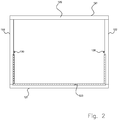
- Fig.2
- die in
Figur 1 dargestellte bevorzugten Ausführungsform der erfindungsgemäßen Vorrichtung in einer Ansicht von vorne; - Fig.3
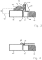
- Details der in
Figur 1 dargestellten bevorzugten Ausführungsform der erfindungsgemäßen Vorrichtung in einer Querschnittsansicht; - Fig. 4
- Details der in der
Fig. 1 dargestellten bevorzugten Ausführungsform der erfindungsgemäßen Vorrichtung in einer weiteren Querschnittsansicht. - Fig. 5
- eine weitere Ausführungsform der erfindungsgemäßen Vorrichtung in einer Ansicht von schräg oben;
- Die in den
Figuren 1 bis 4 dargestellte erfindungsgemäße Schwingtor-Vorrichtung 100 enthält einen schwenkbar gelagerten Torflügel 110, der mit Hilfe einer mittels einer Antriebseinrichtung betreibbaren Schwenkeinrichtung reversibel aus einer ersten Position, in der der Torflügel 110 geöffnet ist, in eine zweite Position verschwenkbar ist, in welcher der Torflügel 110 im Bereich seiner Außenkante an einen zwei horizontale Rahmenstreben 121 und zwei vertikale Rahmenstreben 122 aufweisenden Torrahmen 120 angrenzt und den Torrahmen 120 dadurch verschließt, wobei in verschlossenem Zustand des Torflügels eine im unteren Bereich der Peripherie des Torrahmens angeordnete Torrahmen-Anschlagschiene 123 einer Torflügel-Dichtungsleiste 124 gegenübersteht. - Im Bereich der Innenfläche des Torflügels 110 ist mindestens ein senkrecht zur Flächennormalen des Torflügels 110 verschiebbar gelagerter Dorn 190 angebracht, der aus einer Neutralposition, in der ein unteres Ende des Dorns 190 freisteht, in eine Dichtungsposition überführbar ist, in der das untere Ende des Dorns 190 eine bodennahe Torrahmen-Anschlagschiene 123 hintergreift, um mit dem Torflügel die Torflügel-Dichtungsleiste 124 zum Zweck eines wasserdichten Abschlusses zwischen Torflügel-Dichtungsleiste 124 und Torrahmen-Anschlagschiene 123 gegen die Torrahmen-Anschlagschiene 123 zu drücken.
- Der Dorn 190 ist in einer an der Innenfläche des Torflügels 110 befestigten Führung 112 so angeordnet, dass er in Dichtungsposition des Torflügels 110 vertikal reziprozierbar verschiebbar gelagert ist.
- Das untere Ende des Dorns 190 ist spitz zulaufend ausgebildet, wobei der Dorn 190 im Bereich der Innenfläche des Torflügels 110 so gelagert ist, dass die Spitze des Dorns 190 bei Überführen des Dorns 190 in eine Dichtungsposition für ein Hintergreifen der Torrahmen-Anschlagschiene 123 im Bereich der dem Torflügel 110 fernen Innenfläche der Torrahmen-Anschlagschiene 123 zu liegen kommt.
- Das spitz zulaufende untere Ende des Dorns 190 weist eine im spitzen Winkel zur Längsachse des Dorns 190 verlaufende Flanke 191 auf, die während des Vorgangs des Überführen des Dorns 190 in eine Dichtungsposition durch einen Kontakt mit der Torrahmen-Anschlagschiene 123 eine Hebelwirkung auf die mit dem Torflügel 110 verbundene Torflügel-Dichtungsleiste 124 ausübt, die einen wasserdichten Abschluss zwischen Torflügel-Dichtungsleiste 124 und Torrahmen-Anschlagschiene 123 erzeugt.
- Im Bereich der Innenfläche des Torflügels 110 ist ein von Hand zu betätigendes Rotationselement 195 angebracht, dessen Drehachse flächennormal zum Torflügel 110 ausgerichtet ist und mit Zahnelementen versehen ist, die mit im oberen Bereich des Dornes 190 angebrachten Zahnelementen zusammenwirken, um über ein Drehen des Rotationselementes 195 eine linear vertikale Verschiebung des Dornes 190 zu bewirken.
- In demjenigen Bereich hinter der Torrahmen-Anschlagschiene 123, in dem der Dorn 190 in der Dichtungsposition die Torrahmen-Anschlagschiene 123 hintergreift, ist eine Aussparung 196 zur Aufnahme des unteren Endes des in Dichtungsposition befindlichen Dorns 190 vorgesehen.
- In einem jeweiligen mittleren Abschnitt der beiden vertikalen Rahmenstreben 122 ist jeweils eine Fixierung für ein Drehpunkt-Lager 130 des Torflügels 110 vorgesehen, wobei beide Drehpunkt-Lager 130 jeweils mit einem in einem jeweils mittleren Abschnitt eines als Flügelstreben 111 ausgebildeten seitlichen Flügelteils des Torflügels 110 angeordneten Hebelelement 140 zusammenwirken.
- Im Bereich von Teilen der Außenkante des Torrahmens 122 ist eine Anschlagschiene 123 vorgesehen, die in verschlossenem Zustand des Torflügels 110 an eine in den unterhalb der beiden Hebelelemente 140 angeordneten äußeren Peripheriebereichen der Außenfläche des Torflügels 110 angeordnete Dichtungsleiste 124 angrenzt. Dabei bewirken die Hebelelemente 140 im Zusammenspiel mit der Kraft der Antriebseinrichtung einen wasserdichten Abschluss zwischen Anschlagschiene 123 und Dichtungsleiste 124.
- Ein jeweiliges Drehpunkt-Lager 130 ist von der Ebene des Torrahmens 120 ausgehend in Richtung des von dem Torflügel 110 zu schützenden Innenraumes aus der Ebene des Torrahmens 120 heraus versetzt angeordnet, wobei zur Ebene des Torrahmens 120 ein Abstand von 5 cm ausgebildet ist.
- Ein jeweiliges Drehpunkt-Lager 130 enthält jeweils eine mit einem Hebelelement 140 zusammenwirkende, um eine horizontale Achse 131 rotierbar gelagerte Scheibe 132, wobei das diesbezügliche Achsenlager über ein Halterungselement 150 mit einer betreffenden vertikalen Rahmenstrebe 122 fest verbunden ist.
- Ein Hebelelement 140 ist als vertikal angeordnetes Paneel ausgebildet, das mit einer Angrenzfläche 141 versehen ist, die bei einem Schließen des Torflügels 110 tangential an die Peripherie der rotierbaren Scheibe 132 angrenzt. Ein Paneel 140 ist dabei als Teil eines teilweise offenen Käfigs 133 ausgebildet.
- Ein derartiger Käfig 133 ist für ein Zusammenwirken zwischen der Scheibe 132 und der im Inneren des Käfigs 133 vorgesehenen Angrenzfläche 141 des Paneels 140 nach unten offen ausgebildet und des Weiteren über ein Stützpaneel 134 mit dem als Flügelstreben 111 ausgebildeten seitlichen Flügelteil des Torflügels 110 fest verbunden.
- Die seitlichen Flügelstreben 111 des Torflügels 110 sind oberhalb der Hebelelemente 140 zumindest indirekt mit um eine horizontale Achse drehbar gelagerten Rollen 160 verbunden, wobei die Rollen 160 in jeweiligen Führungsschienen 170 geführt sind, um den Torflügel 110 mittels der Antriebseinrichtung reversibel aus einer horizontalen Lage, in der der Torrahmen 120 geöffnet ist, in eine vertikale Lage zu fördern, in der der Torrahmen 120 geschlossen ist, wobei die seitlichen Flügelstreben 111 des Torflügels 110 parallel zu den vertikalen Rahmenstreben 122 des Torrahmens 120 ausgerichtet sind.
- Die Schwenkeinrichtung enthält zwei jeweils um ein horizontales Achsen-Lager verschwenkbare Hebelarme 180, wobei die seitlichen Flügelstreben 111 des Torflügels 110 unterhalb der Hebelelemente 140 jeweils zumindest indirekt mit einem drehbar gelagerten Ende 181 eines entsprechenden, im Bereich seines anderen Endes 183 um ein horizontales Achsen-Lager 182 verschwenkbaren Hebelarmes 180 verbunden sind, und wobei ein jeweiliges Achsen-Lager 182 an einer jeweiligen vertikalen Rahmenstrebe 122 unterhalb einer Fixierung für ein Drehpunkt-Lager 130 des Torflügels 110 befestigt ist.
- Das oben erläuterte Ausführungsbeispiel der Erfindung dient lediglich dem Zweck eines besseren Verständnisses der durch die Ansprüche vorgegebenen erfindungsgemäßen Lehre, die als solche durch das Ausführungsbeispiel nicht eingeschränkt ist.
Claims (17)
- Schwingtor-Vorrichtung (100) mit einem schwenkbar gelagerten Torflügel (110), der mit Hilfe einer mittels einer Antriebseinrichtung betreibbaren Schwenkeinrichtung reversibel aus einer ersten Position, in der der Torflügel (110) geöffnet ist, in eine zweite Position verschwenkbar ist, in welcher der Torflügel (110) im Bereich seiner Außenkante an einen zwei horizontale Rahmenstreben (121) und zwei vertikale Rahmenstreben (122) aufweisenden Torrahmen (120) angrenzt und den Torrahmen (120) dadurch verschließt, wobei in verschlossenem Zustand des Torflügels (110) eine im unteren Bereich der Peripherie des Torrahmens (110) angeordnete Torrahmen-Anschlagschiene (123) einer Torflügel-Dichtungsleiste (124) gegenübersteht, wobei im Bereich der Innenfläche des Torflügels (110) mindestens ein senkrecht zur Flächennormalen des Torflügels (110) verschiebbar gelagerter Dorn (190) angebracht ist, der aus einer Neutralposition, in der ein unteres Ende des Dorns (190) freisteht, in eine Dichtungsposition überführbar ist, in der das untere Ende des Dorns (190) eine bodennahe Torrahmen-Anschlagschiene (123) hintergreift, um mit dem Torflügel die Torflügel-Dichtungsleiste (124) zum Zweck eines wasserdichten Abschlusses zwischen Torflügel-Dichtungsleiste (124) und Torrahmen-Anschlagschiene (123) gegen die Torrahmen-Anschlagschiene (123) zu drücken, dadurch gekennzeichnet, dass das untere Ende des Dorns (190) spitz zulaufend ausgebildet ist, wobei der Dorn (190) im Bereich der Innenfläche des Torflügels (110) so gelagert ist, dass die Spitze des Dorns (190) bei Überführen des Dorns (190) in eine Dichtungsposition für ein Hintergreifen der Torrahmen-Anschlagschiene (123) im Bereich der dem Torflügel (110) fernen Innenfläche der Torrahmen-Anschlagschiene (123) zu liegen kommt.
- Vorrichtung nach Anspruch 1, dadurch gekennzeichnet, dass der Dorn (190) in einer Dichtungsposition des Torflügels (110) vertikal verschiebbar gelagert ist.
- Vorrichtung nach Anspruch 2, dadurch gekennzeichnet, dass der Dorn (190) in einer an der Innenfläche des Torflügels (110) befestigten Führung (112) reziprozierbar verschiebbar gelagert ist.
- Vorrichtung nach einem der vorhergehenden Ansprüche, dadurch gekennzeichnet, dass das spitz zulaufende untere Ende des Dorns (190) eine im spitzen Winkel zur Längsachse des Dorns (190) verlaufende Flanke (191) aufweist, die während des Vorgangs des Überführen des Dorns (190) in eine Dichtungsposition durch einen Kontakt mit der Torrahmen-Anschlagschiene (123) eine Hebelwirkung auf die mit dem Torflügel verbundene Torflügel-Dichtungsleiste (124) ausübt, die einen wasserdichten Abschlusses zwischen Torflügel-Dichtungsleiste (124) und Torrahmen-Anschlagschiene (123) erzeugt.
- Vorrichtung nach einem der vorhergehenden Ansprüche, dadurch gekennzeichnet, dass im Bereich der Innenfläche des Torflügels (110) ein von Hand zu betätigendes Rotationselement (195) angebracht ist, dessen Drehachse flächennormal zum Torflügel (110) ausgerichtet ist und mit Zahnelementen versehen ist, die mit im oberen Bereich des Dornes (190) angebrachten Zahnelementen zusammenwirken, um über ein Drehen des Rotationselementes (195) eine linear vertikale Verschiebung des Dornes (190) zu bewirken.
- Vorrichtung nach einem der vorhergehenden Ansprüche, dadurch gekennzeichnet, dass in demjenigen Bereich hinter der Torrahmen-Anschlagschiene (123), in dem der Dorn (190) in der Dichtungsposition die Torrahmen-Anschlagschiene (123) hintergreift, eine Aussparung (196) zur Aufnahme des unteren Endes des in Dichtungsposition befindlichen Dorns (190) vorgesehen ist.
- Vorrichtung nach einem der vorhergehenden Ansprüche, dadurch gekennzeichnet, dass in einem jeweiligen mittleren Abschnitt der beiden vertikalen Rahmenstreben (122) jeweils eine Fixierung für ein Drehpunkt-Lager (130) des Torflügels (110) vorgesehen ist, und beide Drehpunkt-Lager (130) jeweils mit einem in einem jeweils mittleren Abschnitt eines seitlichen Flügelteils (111) des Torflügels (110) angeordneten Hebelelement (140) zusammenwirken, wobei im Bereich von Teilen der Außenkante des Torrahmens (122) eine Anschlagschiene (123) vorgesehen ist, die in verschlossenem Zustand des Torflügels (110) an eine in den unterhalb der beiden Hebelelemente (140) angeordneten äußeren Peripheriebereichen der Außenfläche des Torflügels (110) angeordnete Dichtungsleiste (124) angrenzt, und wobei die Hebelelemente (140, 140") im Zusammenspiel mit der Kraft der Antriebseinrichtung einen wasserdichten Abschluss zwischen Anschlagschiene (123) und Dichtungsleiste (124) bewirken.
- Vorrichtung nach Anspruch 7, dadurch gekennzeichnet, dass ein Drehpunkt-Lager (130) außerhalb der Ebene (125) des Torrahmens (120) in fest vorgegebenem Abstand (126) zur Ebene des Torrahmens (120) angeordnet ist.
- Vorrichtung nach Anspruch 8, dadurch gekennzeichnet, dass ein Drehpunkt-Lager (130) von der Ebene des Torrahmens (120) ausgehend in Richtung des von dem Torflügel (110) zu schützenden Innenraumes aus der Ebene des Torrahmens (120) heraus versetzt angeordnet ist.
- Vorrichtung nach einem der Ansprüche 8 oder 9, dadurch gekennzeichnet, dass ein Drehpunkt-Lager (130) in einem Abstand von 3 cm bis 30 cm zur Ebene des Torrahmens (120) angeordnet ist.
- Vorrichtung nach einem der vorhergehenden Ansprüche, dadurch gekennzeichnet, dass ein Drehpunkt-Lager (130) jeweils eine mit einem Hebelelement (140) zusammenwirkende rotierbar gelagerte Scheibe (132) enthält.
- Vorrichtung nach Anspruch 11, dadurch gekennzeichnet, dass die Scheibe (132) um eine horizontale Achse (131) drehbar gelagert ist, wobei das Achsenlager über ein Halterungselement (150) mit einer betreffenden vertikalen Rahmenstrebe (122) fest verbunden ist.
- Vorrichtung nach einem der Ansprüche 11 oder 12, dadurch gekennzeichnet, dass ein Hebelelement (140) als vertikal angeordnetes Paneel (140) ausgebildet ist, mit einer Angrenzfläche (141), die bei einem Schließen des Torflügels (110) tangential an die Peripherie der rotierbaren Scheibe (132) angrenzt.
- Vorrichtung nach Anspruch 13, dadurch gekennzeichnet, dass ein Paneel (140) als Teil eines teilweise offenen Käfigs (133) ausgebildet ist.
- Vorrichtung nach einem der Ansprüche 11-14, dadurch gekennzeichnet, dass ein Käfig (133) für ein Zusammenwirken zwischen der Scheibe (132) und der im Inneren des Käfigs (133) vorgesehenen Angrenzfläche (141) des Paneels (140) nach unten offen ausgebildet ist und über ein Stützpaneel (134) mit einem als Flügelstreben (111) ausgebildeten seitlichen Flügelteil des Torflügels (110) fest verbunden ist.
- Vorrichtung nach einem der vorhergehenden Ansprüche, dadurch gekennzeichnet, dass die seitlichen Flügelstreben (111) des Torflügels (110) oberhalb der Hebelelemente (140) zumindest indirekt mit um eine horizontale Achse drehbar gelagerten Rollen (160) verbunden sind, wobei die Rollen (160) in jeweiligen Führungsschienen (170) geführt sind, um den Torflügel (110) mittels der Antriebseinrichtung reversibel aus einer horizontalen Lage, in der der Torrahmen (120) geöffnet ist, in eine vertikale Lage zu fördern, in der der Torrahmen (120) geschlossen ist, wobei die seitlichen Flügelstreben (111) des Torflügels (110) parallel zu den vertikalen Rahmenstreben (122) des Torrahmens (120) ausgerichtet sind.
- Vorrichtung nach Anspruch 16, dadurch gekennzeichnet, dass die Schwenkeinrichtung zwei jeweils um ein horizontales Achsen-Lager verschwenkbare Hebelarme (180) enthält, wobei die seitlichen Flügelstreben (111) des Torflügels (110) unterhalb der Hebelelemente (140) jeweils zumindest indirekt mit einem drehbar gelagerten Ende (181) eines entsprechenden, im Bereich seines anderen Endes (183) um ein horizontales Achsen-Lager (182) verschwenkbaren Hebelarmes (180) verbunden sind, und wobei ein jeweiliges Achsen-Lager (182) an einer jeweiligen vertikalen Rahmenstrebe (122) unterhalb einer Fixierung für ein Drehpunkt-Lager (130) des Torflügels (110) befestigt ist.
Applications Claiming Priority (1)
| Application Number | Priority Date | Filing Date | Title |
|---|---|---|---|
| DE202015105802.0U DE202015105802U1 (de) | 2015-11-02 | 2015-11-02 | Wasserdichte Schwingtor-Vorrichtung |
Publications (2)
| Publication Number | Publication Date |
|---|---|
| EP3163003A1 EP3163003A1 (de) | 2017-05-03 |
| EP3163003B1 true EP3163003B1 (de) | 2018-07-04 |
Family
ID=54768416
Family Applications (1)
| Application Number | Title | Priority Date | Filing Date |
|---|---|---|---|
| EP16195978.8A Active EP3163003B1 (de) | 2015-11-02 | 2016-10-27 | Wasserdichte schwingtor-vorrichtung |
Country Status (2)
| Country | Link |
|---|---|
| EP (1) | EP3163003B1 (de) |
| DE (1) | DE202015105802U1 (de) |
Citations (1)
| Publication number | Priority date | Publication date | Assignee | Title |
|---|---|---|---|---|
| US3440762A (en) * | 1965-12-02 | 1969-04-29 | Ass Cargo Gear Ab | Watertight vertical doors |
Family Cites Families (5)
| Publication number | Priority date | Publication date | Assignee | Title |
|---|---|---|---|---|
| GB2148377B (en) * | 1983-10-22 | 1987-02-18 | Hardware & Systems Patents Ltd | Improvements in fasteners for doors, windows and the like |
| GB9321141D0 (en) * | 1993-10-13 | 1993-12-01 | Boydell John M | Improvements in up and over garage doors |
| DE10158902C1 (de) * | 2001-11-30 | 2003-01-02 | August Guter | Dichtungs-Vorrichtung für ein Tor |
| FR2840641B1 (fr) * | 2002-06-05 | 2004-10-29 | Novoferm France | Vantail autoporteur pour porte basculante |
| GB2479470B (en) * | 2011-04-20 | 2012-03-07 | Markar Vartanian | Apparatus for flood-proofing a garage with a single panel garage door |
-
2015
- 2015-11-02 DE DE202015105802.0U patent/DE202015105802U1/de not_active Expired - Lifetime
-
2016
- 2016-10-27 EP EP16195978.8A patent/EP3163003B1/de active Active
Patent Citations (1)
| Publication number | Priority date | Publication date | Assignee | Title |
|---|---|---|---|---|
| US3440762A (en) * | 1965-12-02 | 1969-04-29 | Ass Cargo Gear Ab | Watertight vertical doors |
Also Published As
| Publication number | Publication date |
|---|---|
| DE202015105802U1 (de) | 2015-11-18 |
| EP3163003A1 (de) | 2017-05-03 |
Similar Documents
| Publication | Publication Date | Title |
|---|---|---|
| EP3805513A1 (de) | Rolltor | |
| DE69401936T2 (de) | Schiebetür - oder schiebefenster-system | |
| EP1834820A1 (de) | Panoramadach | |
| EP3163003B1 (de) | Wasserdichte schwingtor-vorrichtung | |
| DE102016113085B4 (de) | Wasserdichte Sektionaltor-Vorrichtung | |
| EP2774869A1 (de) | Behälterverschluss | |
| DE19613152B4 (de) | Lüftungsfenster, insb. Rauch-Wärme-Abzug | |
| CH714546A2 (de) | Vorrichtung zum Öffnen einer Gebäudedachöffnung. | |
| DE10029275C1 (de) | Schwenktürflügel für Fahrzeuge des öffentlichen Personennahverkehrs, insbesondere für Busse | |
| DE102008028598B4 (de) | Insektenschutztür | |
| DE102014111301B4 (de) | Wasserdichte schwingtor-vorrichtung | |
| DE3740034C2 (de) | Versenkbare Fensterscheibe für Kraftfahrzeuge | |
| EP1635024A2 (de) | Schwenktür für Fahrzeuge des öffentlichen Personenverkehrs, insbesondere für Busse | |
| DE19745180A1 (de) | Andrückvorrichtung zwischen einem Flügel und einem Blendrahmen einer Tür, eines Fensters oder dergleichen | |
| DE10331708B4 (de) | Windabweiser für ein Fahrzeugdach | |
| DE102023125043B4 (de) | System zum Öffnen einer Öffnung einer Tür | |
| DE102023120352B4 (de) | Fahrzeugeinheit eines konduktiven Ladesystems mit einer Hub-Schwenk-Kulisse | |
| DE202017106967U1 (de) | Eine Scharnieranordnung mit bogenförmigen Führungsmitteln und einer Bremseinrichtung, sowie ein Dachfenster mit einer derartigen Scharnieranordnung | |
| DE1559877C (de) | Beschlag fur wahlweise parallel zu rucksetzbare oder um eine seitliche lot rechte Achse schwenkbare Fensterflugel | |
| DE19923976A1 (de) | Führungs- und Abschirmvorrichtung für eine Schiebeplane | |
| DE1962906C3 (de) | Beschlag fur Dreh-Kipp- oder Dreh-Klappfenster | |
| DE102011117033B4 (de) | Hubtor für eine Toröffnung in einer Wand | |
| EP3299532B1 (de) | Dachfenster | |
| DE202021101589U1 (de) | Tor | |
| DE4419779B4 (de) | Türsicherungsvorrichtung |
Legal Events
| Date | Code | Title | Description |
|---|---|---|---|
| PUAI | Public reference made under article 153(3) epc to a published international application that has entered the european phase |
Free format text: ORIGINAL CODE: 0009012 |
|
| AK | Designated contracting states |
Kind code of ref document: A1 Designated state(s): AL AT BE BG CH CY CZ DE DK EE ES FI FR GB GR HR HU IE IS IT LI LT LU LV MC MK MT NL NO PL PT RO RS SE SI SK SM TR |
|
| AX | Request for extension of the european patent |
Extension state: BA ME |
|
| 17P | Request for examination filed |
Effective date: 20170628 |
|
| GRAP | Despatch of communication of intention to grant a patent |
Free format text: ORIGINAL CODE: EPIDOSNIGR1 |
|
| INTG | Intention to grant announced |
Effective date: 20180227 |
|
| GRAS | Grant fee paid |
Free format text: ORIGINAL CODE: EPIDOSNIGR3 |
|
| GRAA | (expected) grant |
Free format text: ORIGINAL CODE: 0009210 |
|
| AK | Designated contracting states |
Kind code of ref document: B1 Designated state(s): AL AT BE BG CH CY CZ DE DK EE ES FI FR GB GR HR HU IE IS IT LI LT LU LV MC MK MT NL NO PL PT RO RS SE SI SK SM TR |
|
| REG | Reference to a national code |
Ref country code: GB Ref legal event code: FG4D Free format text: NOT ENGLISH |
|
| REG | Reference to a national code |
Ref country code: CH Ref legal event code: EP |
|
| REG | Reference to a national code |
Ref country code: AT Ref legal event code: REF Ref document number: 1014697 Country of ref document: AT Kind code of ref document: T Effective date: 20180715 |
|
| REG | Reference to a national code |
Ref country code: IE Ref legal event code: FG4D Free format text: LANGUAGE OF EP DOCUMENT: GERMAN |
|
| REG | Reference to a national code |
Ref country code: DE Ref legal event code: R096 Ref document number: 502016001409 Country of ref document: DE |
|
| REG | Reference to a national code |
Ref country code: CH Ref legal event code: NV Representative=s name: R.A. EGLI AND CO, PATENTANWAELTE, CH |
|
| REG | Reference to a national code |
Ref country code: FR Ref legal event code: PLFP Year of fee payment: 3 |
|
| REG | Reference to a national code |
Ref country code: NL Ref legal event code: MP Effective date: 20180704 |
|
| REG | Reference to a national code |
Ref country code: LT Ref legal event code: MG4D |
|
| PG25 | Lapsed in a contracting state [announced via postgrant information from national office to epo] |
Ref country code: NL Free format text: LAPSE BECAUSE OF FAILURE TO SUBMIT A TRANSLATION OF THE DESCRIPTION OR TO PAY THE FEE WITHIN THE PRESCRIBED TIME-LIMIT Effective date: 20180704 |
|
| REG | Reference to a national code |
Ref country code: DE Ref legal event code: R082 Ref document number: 502016001409 Country of ref document: DE |
|
| PG25 | Lapsed in a contracting state [announced via postgrant information from national office to epo] |
Ref country code: CZ Free format text: LAPSE BECAUSE OF FAILURE TO SUBMIT A TRANSLATION OF THE DESCRIPTION OR TO PAY THE FEE WITHIN THE PRESCRIBED TIME-LIMIT Effective date: 20180704 Ref country code: BG Free format text: LAPSE BECAUSE OF FAILURE TO SUBMIT A TRANSLATION OF THE DESCRIPTION OR TO PAY THE FEE WITHIN THE PRESCRIBED TIME-LIMIT Effective date: 20181004 Ref country code: PL Free format text: LAPSE BECAUSE OF FAILURE TO SUBMIT A TRANSLATION OF THE DESCRIPTION OR TO PAY THE FEE WITHIN THE PRESCRIBED TIME-LIMIT Effective date: 20180704 Ref country code: RS Free format text: LAPSE BECAUSE OF FAILURE TO SUBMIT A TRANSLATION OF THE DESCRIPTION OR TO PAY THE FEE WITHIN THE PRESCRIBED TIME-LIMIT Effective date: 20180704 Ref country code: LT Free format text: LAPSE BECAUSE OF FAILURE TO SUBMIT A TRANSLATION OF THE DESCRIPTION OR TO PAY THE FEE WITHIN THE PRESCRIBED TIME-LIMIT Effective date: 20180704 Ref country code: IS Free format text: LAPSE BECAUSE OF FAILURE TO SUBMIT A TRANSLATION OF THE DESCRIPTION OR TO PAY THE FEE WITHIN THE PRESCRIBED TIME-LIMIT Effective date: 20181104 Ref country code: NO Free format text: LAPSE BECAUSE OF FAILURE TO SUBMIT A TRANSLATION OF THE DESCRIPTION OR TO PAY THE FEE WITHIN THE PRESCRIBED TIME-LIMIT Effective date: 20181004 Ref country code: GR Free format text: LAPSE BECAUSE OF FAILURE TO SUBMIT A TRANSLATION OF THE DESCRIPTION OR TO PAY THE FEE WITHIN THE PRESCRIBED TIME-LIMIT Effective date: 20181005 Ref country code: FI Free format text: LAPSE BECAUSE OF FAILURE TO SUBMIT A TRANSLATION OF THE DESCRIPTION OR TO PAY THE FEE WITHIN THE PRESCRIBED TIME-LIMIT Effective date: 20180704 Ref country code: SE Free format text: LAPSE BECAUSE OF FAILURE TO SUBMIT A TRANSLATION OF THE DESCRIPTION OR TO PAY THE FEE WITHIN THE PRESCRIBED TIME-LIMIT Effective date: 20180704 |
|
| PG25 | Lapsed in a contracting state [announced via postgrant information from national office to epo] |
Ref country code: ES Free format text: LAPSE BECAUSE OF FAILURE TO SUBMIT A TRANSLATION OF THE DESCRIPTION OR TO PAY THE FEE WITHIN THE PRESCRIBED TIME-LIMIT Effective date: 20180704 Ref country code: AL Free format text: LAPSE BECAUSE OF FAILURE TO SUBMIT A TRANSLATION OF THE DESCRIPTION OR TO PAY THE FEE WITHIN THE PRESCRIBED TIME-LIMIT Effective date: 20180704 Ref country code: LV Free format text: LAPSE BECAUSE OF FAILURE TO SUBMIT A TRANSLATION OF THE DESCRIPTION OR TO PAY THE FEE WITHIN THE PRESCRIBED TIME-LIMIT Effective date: 20180704 Ref country code: HR Free format text: LAPSE BECAUSE OF FAILURE TO SUBMIT A TRANSLATION OF THE DESCRIPTION OR TO PAY THE FEE WITHIN THE PRESCRIBED TIME-LIMIT Effective date: 20180704 |
|
| REG | Reference to a national code |
Ref country code: DE Ref legal event code: R097 Ref document number: 502016001409 Country of ref document: DE |
|
| PG25 | Lapsed in a contracting state [announced via postgrant information from national office to epo] |
Ref country code: EE Free format text: LAPSE BECAUSE OF FAILURE TO SUBMIT A TRANSLATION OF THE DESCRIPTION OR TO PAY THE FEE WITHIN THE PRESCRIBED TIME-LIMIT Effective date: 20180704 Ref country code: IT Free format text: LAPSE BECAUSE OF FAILURE TO SUBMIT A TRANSLATION OF THE DESCRIPTION OR TO PAY THE FEE WITHIN THE PRESCRIBED TIME-LIMIT Effective date: 20180704 Ref country code: RO Free format text: LAPSE BECAUSE OF FAILURE TO SUBMIT A TRANSLATION OF THE DESCRIPTION OR TO PAY THE FEE WITHIN THE PRESCRIBED TIME-LIMIT Effective date: 20180704 |
|
| PLBE | No opposition filed within time limit |
Free format text: ORIGINAL CODE: 0009261 |
|
| STAA | Information on the status of an ep patent application or granted ep patent |
Free format text: STATUS: NO OPPOSITION FILED WITHIN TIME LIMIT |
|
| PG25 | Lapsed in a contracting state [announced via postgrant information from national office to epo] |
Ref country code: SM Free format text: LAPSE BECAUSE OF FAILURE TO SUBMIT A TRANSLATION OF THE DESCRIPTION OR TO PAY THE FEE WITHIN THE PRESCRIBED TIME-LIMIT Effective date: 20180704 Ref country code: SK Free format text: LAPSE BECAUSE OF FAILURE TO SUBMIT A TRANSLATION OF THE DESCRIPTION OR TO PAY THE FEE WITHIN THE PRESCRIBED TIME-LIMIT Effective date: 20180704 Ref country code: DK Free format text: LAPSE BECAUSE OF FAILURE TO SUBMIT A TRANSLATION OF THE DESCRIPTION OR TO PAY THE FEE WITHIN THE PRESCRIBED TIME-LIMIT Effective date: 20180704 |
|
| 26N | No opposition filed |
Effective date: 20190405 |
|
| REG | Reference to a national code |
Ref country code: BE Ref legal event code: MM Effective date: 20181031 |
|
| PG25 | Lapsed in a contracting state [announced via postgrant information from national office to epo] |
Ref country code: LU Free format text: LAPSE BECAUSE OF NON-PAYMENT OF DUE FEES Effective date: 20181027 Ref country code: MC Free format text: LAPSE BECAUSE OF FAILURE TO SUBMIT A TRANSLATION OF THE DESCRIPTION OR TO PAY THE FEE WITHIN THE PRESCRIBED TIME-LIMIT Effective date: 20180704 |
|
| REG | Reference to a national code |
Ref country code: IE Ref legal event code: MM4A |
|
| PG25 | Lapsed in a contracting state [announced via postgrant information from national office to epo] |
Ref country code: SI Free format text: LAPSE BECAUSE OF FAILURE TO SUBMIT A TRANSLATION OF THE DESCRIPTION OR TO PAY THE FEE WITHIN THE PRESCRIBED TIME-LIMIT Effective date: 20180704 Ref country code: BE Free format text: LAPSE BECAUSE OF NON-PAYMENT OF DUE FEES Effective date: 20181031 |
|
| PG25 | Lapsed in a contracting state [announced via postgrant information from national office to epo] |
Ref country code: IE Free format text: LAPSE BECAUSE OF NON-PAYMENT OF DUE FEES Effective date: 20181027 |
|
| PG25 | Lapsed in a contracting state [announced via postgrant information from national office to epo] |
Ref country code: MT Free format text: LAPSE BECAUSE OF FAILURE TO SUBMIT A TRANSLATION OF THE DESCRIPTION OR TO PAY THE FEE WITHIN THE PRESCRIBED TIME-LIMIT Effective date: 20180704 |
|
| PG25 | Lapsed in a contracting state [announced via postgrant information from national office to epo] |
Ref country code: TR Free format text: LAPSE BECAUSE OF FAILURE TO SUBMIT A TRANSLATION OF THE DESCRIPTION OR TO PAY THE FEE WITHIN THE PRESCRIBED TIME-LIMIT Effective date: 20180704 |
|
| PG25 | Lapsed in a contracting state [announced via postgrant information from national office to epo] |
Ref country code: PT Free format text: LAPSE BECAUSE OF FAILURE TO SUBMIT A TRANSLATION OF THE DESCRIPTION OR TO PAY THE FEE WITHIN THE PRESCRIBED TIME-LIMIT Effective date: 20180704 |
|
| PG25 | Lapsed in a contracting state [announced via postgrant information from national office to epo] |
Ref country code: CY Free format text: LAPSE BECAUSE OF FAILURE TO SUBMIT A TRANSLATION OF THE DESCRIPTION OR TO PAY THE FEE WITHIN THE PRESCRIBED TIME-LIMIT Effective date: 20180704 Ref country code: HU Free format text: LAPSE BECAUSE OF FAILURE TO SUBMIT A TRANSLATION OF THE DESCRIPTION OR TO PAY THE FEE WITHIN THE PRESCRIBED TIME-LIMIT; INVALID AB INITIO Effective date: 20161027 Ref country code: MK Free format text: LAPSE BECAUSE OF NON-PAYMENT OF DUE FEES Effective date: 20180704 |
|
| PGFP | Annual fee paid to national office [announced via postgrant information from national office to epo] |
Ref country code: DE Payment date: 20251031 Year of fee payment: 10 |
|
| PGFP | Annual fee paid to national office [announced via postgrant information from national office to epo] |
Ref country code: GB Payment date: 20251001 Year of fee payment: 10 |
|
| PGFP | Annual fee paid to national office [announced via postgrant information from national office to epo] |
Ref country code: AT Payment date: 20251014 Year of fee payment: 10 |
|
| PGFP | Annual fee paid to national office [announced via postgrant information from national office to epo] |
Ref country code: FR Payment date: 20251031 Year of fee payment: 10 |
|
| REG | Reference to a national code |
Ref country code: CH Ref legal event code: U11 Free format text: ST27 STATUS EVENT CODE: U-0-0-U10-U11 (AS PROVIDED BY THE NATIONAL OFFICE) Effective date: 20260129 |
|
| PGFP | Annual fee paid to national office [announced via postgrant information from national office to epo] |
Ref country code: CH Payment date: 20260129 Year of fee payment: 10 |