EP3154182B1 - Stromwandlungsvorrichtung - Google Patents
Stromwandlungsvorrichtung Download PDFInfo
- Publication number
- EP3154182B1 EP3154182B1 EP14894405.1A EP14894405A EP3154182B1 EP 3154182 B1 EP3154182 B1 EP 3154182B1 EP 14894405 A EP14894405 A EP 14894405A EP 3154182 B1 EP3154182 B1 EP 3154182B1
- Authority
- EP
- European Patent Office
- Prior art keywords
- control
- characteristic data
- inverter unit
- output frequency
- unit
- Prior art date
- Legal status (The legal status is an assumption and is not a legal conclusion. Google has not performed a legal analysis and makes no representation as to the accuracy of the status listed.)
- Active
Links
Images


Classifications
-
- H—ELECTRICITY
- H02—GENERATION; CONVERSION OR DISTRIBUTION OF ELECTRIC POWER
- H02P—CONTROL OR REGULATION OF ELECTRIC MOTORS, ELECTRIC GENERATORS OR DYNAMO-ELECTRIC CONVERTERS; CONTROLLING TRANSFORMERS, REACTORS OR CHOKE COILS
- H02P23/00—Arrangements or methods for the control of AC motors characterised by a control method other than vector control
- H02P23/0004—Control strategies in general, e.g. linear type, e.g. P, PI, PID, using robust control
- H02P23/0027—Control strategies in general, e.g. linear type, e.g. P, PI, PID, using robust control using different modes of control depending on a parameter, e.g. the speed
-
- H—ELECTRICITY
- H02—GENERATION; CONVERSION OR DISTRIBUTION OF ELECTRIC POWER
- H02P—CONTROL OR REGULATION OF ELECTRIC MOTORS, ELECTRIC GENERATORS OR DYNAMO-ELECTRIC CONVERTERS; CONTROLLING TRANSFORMERS, REACTORS OR CHOKE COILS
- H02P23/00—Arrangements or methods for the control of AC motors characterised by a control method other than vector control
- H02P23/20—Controlling the acceleration or deceleration
-
- H—ELECTRICITY
- H02—GENERATION; CONVERSION OR DISTRIBUTION OF ELECTRIC POWER
- H02P—CONTROL OR REGULATION OF ELECTRIC MOTORS, ELECTRIC GENERATORS OR DYNAMO-ELECTRIC CONVERTERS; CONTROLLING TRANSFORMERS, REACTORS OR CHOKE COILS
- H02P27/00—Arrangements or methods for the control of AC motors characterised by the kind of supply voltage
- H02P27/04—Arrangements or methods for the control of AC motors characterised by the kind of supply voltage using variable-frequency supply voltage, e.g. inverter or converter supply voltage
- H02P27/06—Arrangements or methods for the control of AC motors characterised by the kind of supply voltage using variable-frequency supply voltage, e.g. inverter or converter supply voltage using DC to AC converters or inverters
Definitions
- the present invention relates to a power conversion devices that drive and control an electric motor.
- JP-H06-42761 B2 A background art in this technical field is disclosed in JP-H06-42761 B2 .
- a control method for an electric vehicle control device that drives and controls an induction motor by a variable-voltage variable-frequency inverter.
- an output voltage / output frequency (hereinafter, referred to as a V/F characteristic) of the above-described inverter so as to maintain a set value in order to obtain constant acceleration and deceleration performance
- the set value of the above-described V/F characteristic is made different between during powering time and during regeneration time, and the V/F characteristic during the regeneration time is set to a smaller value than the V/F characteristic during the powering time (see claims).
- an inverter that drives a motor based on a V/F characteristic which is a ratio of an output voltage to an output frequency that have been stored, includes: a storage means that stores a plurality of motor circuit constants; means for setting at least one of a model, an output, and the number of poles of the motor to be used; an operating state setting means that sets an operating state such as accelerating, driving at a constant speed, and decelerating; and means for setting the V/F characteristic based on at least one of the model, the output, and the number of poles of the motor and the operating state.” (see claims).
- US2007/216340 discloses a method and an apparatus that aim to reduce a speed of an alternating current motor and to shorten a time period of reducing the speed without bringing about a failure by reducing the speed in an overexcited state by making a time constant of a first degree delay filter larger than a time constant in a normal control state, monitoring a current flowing in the alternating current motor and adjusting the time constant in accordance with a current flowing in the alternating current motor in reducing the speed in driving the alternating current motor by a voltage type inverter including a voltage correcting portion for correcting a given voltage instruction by using a value constituted by passing a direct current bus voltage detected value through the first degree delay filter.
- JPS63268498 discloses an acceleration-deceleration discrimination circuit that discriminates whether an induction motor is accelerating or decelerating.
- An acceleration V/F pattern generation circuit outputs the optimum V/F pattern for the acceleration of the motor.
- V/F pattern generation circuit outputs the optimum V/F pattern for the deceleration of the motor.
- JPH09140181 discloses an inverter in which a positive/negative discriminating circuit discriminates between powering state and regenerative state based on the polarity of torque current. At the time of regeneration, a switch circuit is closed to make a switching from a voltage setter providing an AVR level setting for powering to a voltage setter providing an AVR level setting for regeneration in order to increase the V/f ratio. Consequently, an induction motor is brought into over exciting state and a part of regenerative energy is absorbed by the induction motor itself.
- JPS56129596 discloses an AC motor controlling method wherein a star-delta selector switch, an adjuster of V/F (Voltage/ Frequency) ratio at AC motor terminals, and a V/F ratio selector switch are furnished.
- the star-delta selector switch changes the AC motor winding connection, selecting the star for a low speed running and the delta for a high speed running.
- the V/F selector switch selects command signals to alter the output voltage of the PWM inverter so that the V/F ratio may be smaller in the low speed range and larger in the high speed range.
- motor winding connection modification and V/F ratio variation effected together result in a greatly decreased line current, ensuring a continuous torque characteristic suiting given loads even in the low speed range.
- JPS56129596 discloses an AC motor controlling method wherein a star-delta selector switch, an adjuster of V/F (Voltage/ Frequency) ratio at AC motor terminals, and a V/F ratio selector switch are furnished.
- the star-delta selector switch changes the AC motor winding connection, selecting the star for a low speed running and the delta for a high speed running.
- the V/F selector switch selects command signals to alter the output voltage of the PWM inverter so that the V/F ratio may be smaller in the low speed range and larger in the high speed range.
- JP 2001 66293 A refers to a method for driving a synchronous motor, in order to reduce acceleration and deceleration time by individually setting the ratio pattern between power and frequency being outputted by a voltage-type inverter among acceleration operation, low-speed operation, and deceleration operation and switching the ratio pattern according to the change in an operation state.
- JP-H06-42761 B2 there is described a variable-voltage variable-frequency inverter having a system for increasing regeneration performance in a high speed range by setting the V/F characteristic during the regeneration time to a smaller value than the V/F characteristic during the powering time.
- the method according to JP-H06-42761 B2 may not necessarily lead to an improvement of the regeneration performance.
- the inverter by setting the V/F characteristic during the regeneration time to a smaller value than the V/F characteristic during the powering time, electric motor loss becomes small, and regenerative torque may be reduced.
- JP-H10-174491 A there is described an inverter, which drives a motor based on a V/F characteristic that has been stored, having a system for setting the V/F characteristic based on at least one of a model, output, and the number of poles of the motor and a setting of an operating state such as accelerating, driving at a constant speed, and decelerating.
- JP-H10-174491 A assumes a square reduced torque characteristic of a fan in general, and there is described a method for setting the V/F characteristic while decelerating by also using the square reduced characteristic. In the same way as in JP-H06-42761 B2 , this may reduce the regenerative torque.
- An objective of the present invention is to provide a power conversion device with which, while decelerating an electric motor, regenerative torque is secured in a high speed range and electric motor loss is reduced in a low speed range.
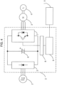
- FIG. 4 an exemplary control system including an inverter device according to the present invention is illustrated.
- Power is supplied from a three-phase alternating-current (AC) power supply 1 to an inverter device 2, and an AC electric motor 3 is driven.
- a load 4 used in a machine such as a fan and a conveyer is connected.
- the converter unit 5 converts an AC voltage supplied from the three-phase AC power supply or a power generator into a direct-current (DC) voltage.
- the DC voltage smoothed by the smoothing capacitor 6 is converted into an AC power by the inverter unit 7.
- the drive circuit 8 drives each switching element of the inverter unit 7 according to a drive control signal that is output from the control circuit 9.
- Information such as an output frequency, acceleration and deceleration time, and an operating state such as operating and stop can be set from an operator 10.
- An operating state signal within the inverter device is transmitted from the operator 10 to the control circuit 9.
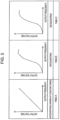
- FIG. 1 is a view illustrating a relationship between an output voltage and an output frequency controlled by an inverter unit (V/F characteristic). This is the most basic V/F characteristic, and during powering time and the like, a ratio of the output voltage / output frequency is output to be constant.
- V/F characteristic This is the most basic V/F characteristic, and during powering time and the like, a ratio of the output voltage / output frequency is output to be constant.
- the V/F characteristic is made different from the V/F characteristic during the powering time in driving. It is set such that a value of the V/F characteristic during the regeneration time is larger than a value thereof during the powering time in a region having a high output frequency and is smaller than the value thereof during the powering time in a region having a small output frequency.
- the regeneration time in a case where the V/F characteristic is high while decelerating, it enters a so-called overexcited state in which an excitation current of an electric motor increases while electric motor loss increases. Due to an increase of the electric motor loss, regeneration energy is reduced, and the regenerative torque of an inverter is relatively increased.
- the regenerative torque may be increased rather by increasing the output voltage, or by setting the V/F characteristic to a larger value than the value thereof during the powering time.
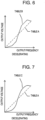
- FIG. 2 there is illustrated an exemplary load torque requested in a case where deceleration is performed by using the V/F characteristic of FIG. 1 .
- an inertia load although the load torque while decelerating is dependent on the length of deceleration time, substantially constant torque across the entire driving frequency is requested in many cases.
- an exemplary regenerative torque characteristic for each frequency while the inverter is driving is denoted by a solid line.
- the maximum regenerative torque is determined by a rated current of the inverter, a capacitor capacity of a smoothing capacitor, an overvoltage trip threshold, a characteristic of electric motor loss and the like, and it changes with frequency.
- the regenerative torque has a characteristic in which the torque is increased as it changes from a high speed to a low speed.
- the present invention it is controlled such that the value of the V/F characteristic during the regeneration time is a larger value than the value thereof during the powering time in a high output frequency region and is smaller than the value thereof during the powering time in a small output frequency region.
- FIG. 5 is a graph illustrating the V/F characteristic of a first example.
- table A the V/F characteristic while accelerating and driving at a constant speed is set, and in tables B and C, the V/F characteristic while decelerating is set.
- table A a ratio of the output voltage / output frequency is output in a fixed manner (predetermined value).
- a value of the V/F characteristic is set to be higher than the fixed value indicated in the table A in the high speed range (first frequency range) and is lower than the fixed value in the low speed range (second frequency range).
- a storage area of the control circuit 9 is set such that a plurality of V/F characteristics and the operating state signal illustrated in FIG. 5 can be stored. Based on the operating state signal, the control circuit 9 selects the table A while accelerating and driving at driving at a constant speed and the table B or the table C while decelerating. Selection between the table B or the table C while decelerating may be set from the operator 10 in advance. Based on the operating state signal indicating the decelerating, accelerating, and driving at a constant speed and the V/F characteristic that has been stored, the control circuit 9 determines the output voltage for each output frequency. Accordingly, the electric motor is successively accelerated or decelerated according to the acceleration and deceleration time that has been set.
- the V/F line of the table A is shifted upward in a part of the high speed range and is shifted downward in a part of the low speed range, which are linked together.
- the table B is constituted of straight lines, whereby it has an advantage that it can be easily created on software and a width of shifting and a break point can be set.
- the table C is the table B turned into a curved shape. It has an advantage that a possibility of causing an unstable phenomenon such as hunting is decreased by eliminating the part of the break point.
- FIG. 8 is a view illustrating a time hysteresis when switching from a state in which the output voltage is increased while decelerating to driving at a constant speed (or accelerating).
- the control circuit 9 acquires operation information of accelerating, driving at a constant speed, and decelerating, and according to this information, performs control by changing the table of the output voltage / output frequency. In changing the output voltage accompanying a change of the table, it is switched gradually by using the time ⁇ T in FIG. 8 . Accordingly, it is possible to drive while suppressing growth of an output current of the AC electric motor.
- the time of switching from decelerating to driving at a constant speed or accelerating and the time of switching from driving at a constant speed or accelerating to decelerating different.
- the unstable phenomenon such as hunting may remain due to the switching.
- tripping may be easily caused unless it is quickly switched (and the unstable phenomenon such as the hunting may remain).
- a speed of the switching be adjusted in order to stabilize rotation as well as to avoid the tripping.
- the time of the switching from driving at a constant speed or accelerating to decelerating may be made faster than the time of the switching from decelerating to driving at a constant speed or accelerating.
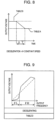
- FIG. 9 is a view illustrating a V/F characteristic according to a second example.
- the table A of FIG. 5 is set for the V/F characteristic while accelerating and driving at a constant speed
- a table D is set for the V/F characteristic while decelerating.
- the V/F characteristic of the table D is set to be high in the high speed range and to be low in the low speed range, which is the same; however, there is a difference in that a ratio of a high speed range frequency range FH (first frequency range) to a low speed range frequency range FL (second frequency range) is changed.
- the ratio of FH to FL may be set from the operator 10 in advance.
- the control circuit 9 sets the table D and stores it in the storage area.
- FIG. 9 is a graph illustrating an FH > FL characteristic.
- FIG. 10 is a graph illustrating a V/F characteristic of a third example.
- the table A of FIG. 5 is set for the V/F characteristic while accelerating and driving at a constant speed
- a table E is set for the V/F characteristic while decelerating.
- the V/F characteristic of the table E is set to be high in the high speed range and to be low in the low speed range, which is the same; however, there is a difference in that a high speed range output voltage level VH and a low speed range output voltage level VL are changed.
- the VH and the VL may be set from the operator 10 in advance. Based on this, the control circuit 9 sets the table E and stores it in the storage area. In FIG. 10 , the VH and VL are set to have positive values.
- the overvoltage and overcurrent tripping is less likely to be caused in the first frequency range while the motor loss is more likely to be decreased in the second frequency range.
- VH and VL By setting the VH and VL on a negative side, an opposite effect can be obtained. By making such setting, it is possible to perform control according to the load torque and the motor efficiency that are requested.
- a user can set applicability of the present invention to the inverter device from the operator.
- a table to be used during the regeneration time is selected by the user selecting the type of load from the operator.
- the load is a load to be a target of the present invention such as a fan and the like
- an appropriate table from among the table B to the table E may be set as the V/F characteristic during the regeneration time, and in a case where it is any other load, the same table used during the powering time may be used also during the regeneration time.
- control priority item regenerative torque priority, motor efficiency priority, and the like
- V/F characteristic during the powering time (accelerating and driving at a constant speed), which is the basic characteristic illustrated in FIG. 1 ; however, it is not necessarily to be limited to this, and a different V/F characteristic may also be used.
- a power conversion device in a power conversion device according to the present invention, it is possible to prevent the overvoltage and overcurrent tripping by increasing the regenerative torque by setting the V/F characteristic high in the high speed range while decelerating. In the low speed range, by setting the V/F characteristic low, it is possible to operate the electric motor repeatedly without burning, whereby it is effective in terms of efficiency as well.
Landscapes
- Engineering & Computer Science (AREA)
- Power Engineering (AREA)
- Control Of Ac Motors In General (AREA)
Claims (9)
- Leistungswandlervorrichtung (2), die Folgendes umfasst:eine Wandlereinheit (5), die dazu ausgelegt ist, aufgenommene Wechselstromleistung in Gleichstromleistung umzuwandeln;einen Glättungskondensator (6), der dazu ausgelegt ist, die durch die Wandlereinheit (5) umgewandelte Gleichstromleistung zu glätten;eine Wechselrichtereinheit (7), die dazu ausgelegt ist, die durch den Glättungskondensator (6) geglättete Gleichstromleistung in Wechselstromleistung umzuwandeln; undeine Steuereinheit (9), die dazu ausgelegt ist, die Wechselrichtereinheit (7) zu steuern,wobei die Steuereinheit (9) dazu ausgelegt ist, die Wechselrichtereinheit (7) so zu steuern, dass in einem ersten Ausgangsfrequenzbereich ein Wert eines Verhältnisses zwischen der Ausgangsspannung und der Ausgangsfrequenz während einer Regenerationszeit größer ist als ein Wert eines Verhältnisses zwischen der Ausgangsspannung und der Ausgangsfrequenz während einer Antriebszeit;wobei die Steuereinheit (9) dazu ausgelegt ist, eine Vielzahl von charakteristischen Daten über das Verhältnis zwischen der Ausgangsspannung und der Ausgangsfrequenz zu speichern, wobei jede aus der Vielzahl von charakteristischen Daten eine Beziehung zwischen der Ausgangsspannung und der Ausgangsfrequenz darstellt, und die Wechselrichtereinheit (7) basierend auf unterschiedlichen aus der Vielzahl von charakteristischen Daten zwischen während der Regenerationszeit und während der Antriebszeit zu steuern;wobei die Steuereinheit (9) dazu ausgelegt ist, die Wechselrichtereinheit (7) zu steuern, indem sie die charakteristischen Daten, auf denen beruhend die Wechselrichtereinheit (7) gesteuert wird, auf eine andere aus der Vielzahl von charakteristischen Daten gemäß Betriebsinformationen ändert, während beschleunigt, bei konstanter Geschwindigkeit gefahren und verlangsamt wird, und eine Änderung der charakteristischen Daten allmählich über einen vorbestimmten Zeitraum hinweg durchgeführt wird; undwobei der Wert des Verhältnisses zwischen der Ausgangsspannung und der Ausgangsfrequenz während der Antriebszeit im ersten Ausgangsfrequenzbereich und im zweiten Ausgangsfrequenzbereich ein vorbestimmter Wert ist,
dadurch gekennzeichnet, dass
die Steuereinheit (9) dazu ausgelegt ist, die Wechselrichtereinheit (7) so zu steuern, dass der Wert des Verhältnisses zwischen der Ausgangsspannung und der Ausgangsfrequenz während der Regenerationszeit kleiner ist als ein Wert eines Verhältnisses zwischen der Ausgangsspannung und der Ausgangsfrequenz während der Antriebszeit in einem zweiten Ausgangsfrequenzbereich, der kleinere Frequenzen als im ersten Ausgangsfrequenzbereich aufweist. - Leistungswandlervorrichtung (2) nach Anspruch 1, wobei die Zeit, die zur Änderung der charakteristischen Daten benötigt wird, je nachdem, ob von Fahren bei konstanter Geschwindigkeit oder von Beschleunigen auf Verlangsamen geschaltet wird oder ob von Verlangsamen zu Fahren bei konstanter Geschwindigkeit oder Beschleunigen, unterschiedlich ist.
- Leistungswandlervorrichtung (2) nach Anspruch 1, wobei die Steuereinheit (9) dazu ausgelegt ist, die Wechselrichtereinheit (7) durch Ändern eines Verhältnisses der Größe des ersten Bereichs und des zweiten Bereichs zu steuern.
- Leistungswandlervorrichtung (2) nach Anspruch 1, wobei die Steuereinheit (9) dazu ausgelegt ist, die Wechselrichtereinheit (7) durch individuelles Ändern der Ausgangsspannung im ersten Bereich und der Ausgangsspannung im zweiten Bereich zu steuern.
- Leistungswandlervorrichtung (2) nach Anspruch 1, wobei die charakteristischen Daten, auf denen beruhend die Wechselrichtereinheit (7) während der Regenerationszeit gesteuert wird, durch einen Benutzer der Leistungswandlervorrichtung (2) aus einer Vielzahl von charakteristischen Daten ausgewählt werden.
- Leistungswandlervorrichtung (2) nach Anspruch 1, ferner umfassend:eine Betriebseinheit (10), die dazu ausgelegt ist, es einem Benutzer zu ermöglichen, den Betrieb der Leistungswandlervorrichtung (2) durchzuführen, wobeidie Betriebseinheit (10) in der Lage ist, einen Lasttyp oder ein Steuerprioritätselement als Steuerziel auszuwählen, unddie Steuereinheit (9) durch Verwenden der charakteristischen Daten, die dem von der Betriebseinheit (10) ausgewählten Lasttyp oder Steuerprioritätselement entsprechen, die Steuerung der Wechselrichtereinheit (7) durchführt.
- Leistungswandlervorrichtung (2), die Folgendes umfasst:eine Wandlereinheit (5), die dazu ausgelegt ist, aufgenommene Wechselstromleistung in Gleichstromleistung umzuwandeln;einen Glättungskondensator (6), der dazu ausgelegt ist, die durch die Wandlereinheit (5) umgewandelte Gleichstromleistung zu glätten;eine Wechselrichtereinheit (7), die dazu ausgelegt ist, die durch den Glättungskondensator (6) geglättete Gleichstromleistung in Wechselstromleistung umzuwandeln; undeine Steuereinheit (9), die dazu ausgelegt ist, die Wechselrichtereinheit (7) zu steuern,wobei die Steuereinheit (9) dazu ausgelegt ist, die Wechselrichtereinheit (7) so zu steuern, dass ein Wert eines Verhältnisses zwischen der Ausgangsspannung und der Ausgangsfrequenz während einer Regenerationszeit größer ist als ein vorbestimmter Wert in einem ersten Ausgangsfrequenzbereich, in dem die Ausgangsfrequenzen größer sind als eine vorbestimmte Frequenz;wobei die Steuereinheit (9) dazu ausgelegt ist, eine Vielzahl von charakteristischen Daten über das Verhältnis zwischen der Ausgangsspannung und der Ausgangsfrequenz zu speichern, wobei jede aus der Vielzahl von charakteristischen Daten eine Beziehung zwischen der Ausgangsspannung und der Ausgangsfrequenz darstellt, und die Wechselrichtereinheit (7) basierend auf unterschiedlichen aus der Vielzahl von charakteristischen Daten zwischen während der Regenerationszeit und während der Antriebszeit zu steuern;wobei die Steuereinheit (9) dazu ausgelegt ist, die Wechselrichtereinheit (7) zu steuern, indem sie die charakteristischen Daten, auf denen beruhend die Wechselrichtereinheit (7) gesteuert wird, auf eine andere aus der Vielzahl von charakteristischen Daten gemäß Betriebsinformationen ändert, während beschleunigt, bei konstanter Geschwindigkeit gefahren und verlangsamt wird, und eine Änderung der charakteristischen Daten allmählich über einen vorbestimmten Zeitraum erfolgt;dadurch gekennzeichnet, dassdie Steuereinheit (9) dazu ausgelegt ist, die Wechselrichtereinheit (7) so zu steuern, dass der Wert des Verhältnisses zwischen der Ausgangsspannung und der Ausgangsfrequenz während der Regenerationszeit kleiner ist als der vorbestimmte Wert in einem zweiten Ausgangsfrequenzbereich, in dem die Ausgangsfrequenzen kleiner sind als die vorbestimmte Frequenz.
- Leistungswandlervorrichtung (2) nach Anspruch 7, wobei die vorbestimmte Frequenz durch Einstellen geändert werden kann.
- Leistungswandlervorrichtung (2) nach Anspruch 7, ferner Folgendes umfassend:eine Betriebseinheit (10), die dazu ausgelegt ist, es einem Benutzer zu ermöglichen, den Betrieb der Leistungswandlervorrichtung (2) durchzuführen, wobeidie Betriebseinheit (10) in der Lage ist, einen Lasttyp oder ein Steuerprioritätselement als Steuerziel auszuwählen, unddie Steuereinheit (9) ausgelegt ist, durch Verwenden der charakteristischen Daten, die dem von der Betriebseinheit (10) ausgewählten Lasttyp oder Steuerprioritätselement entsprechen, die Steuerung der Wechselrichtereinheit (7) durchzuführen.
Applications Claiming Priority (1)
| Application Number | Priority Date | Filing Date | Title |
|---|---|---|---|
| PCT/JP2014/065173 WO2015189884A1 (ja) | 2014-06-09 | 2014-06-09 | 電力変換装置 |
Publications (3)
| Publication Number | Publication Date |
|---|---|
| EP3154182A1 EP3154182A1 (de) | 2017-04-12 |
| EP3154182A4 EP3154182A4 (de) | 2018-03-14 |
| EP3154182B1 true EP3154182B1 (de) | 2024-07-31 |
Family
ID=54833017
Family Applications (1)
| Application Number | Title | Priority Date | Filing Date |
|---|---|---|---|
| EP14894405.1A Active EP3154182B1 (de) | 2014-06-09 | 2014-06-09 | Stromwandlungsvorrichtung |
Country Status (4)
| Country | Link |
|---|---|
| EP (1) | EP3154182B1 (de) |
| JP (1) | JP6438950B2 (de) |
| CN (1) | CN106105011B (de) |
| WO (1) | WO2015189884A1 (de) |
Families Citing this family (2)
| Publication number | Priority date | Publication date | Assignee | Title |
|---|---|---|---|---|
| CN106452277A (zh) * | 2016-12-15 | 2017-02-22 | 江西江特电气集团有限公司 | 一种变频器双vf曲线控制方法 |
| CN114337444A (zh) * | 2021-11-26 | 2022-04-12 | 上海力申科学仪器有限公司 | 高速离心机非正常停机的电机降速控制方法 |
Family Cites Families (12)
| Publication number | Priority date | Publication date | Assignee | Title |
|---|---|---|---|---|
| JPS56129596A (en) * | 1980-03-17 | 1981-10-09 | Toyo Electric Mfg Co Ltd | Ac motor controlling method |
| CN1006265B (zh) * | 1985-04-01 | 1989-12-27 | 陶凤白 | 一种用于无级变速的交流电动机 |
| JPS63268498A (ja) * | 1987-04-25 | 1988-11-07 | Fuji Electric Co Ltd | 電動機駆動用インバ−タの加減速切換え回路 |
| JPH06165583A (ja) * | 1992-11-25 | 1994-06-10 | Toshiba Corp | インバータ装置 |
| JPH09140181A (ja) * | 1995-11-16 | 1997-05-27 | Hitachi Ltd | インバータ装置 |
| JPH1141950A (ja) * | 1997-07-24 | 1999-02-12 | Toyota Autom Loom Works Ltd | インバータ回路 |
| JP2000166293A (ja) * | 1998-11-24 | 2000-06-16 | Fuji Electric Co Ltd | 同期電動機の駆動方法 |
| JP2002171780A (ja) * | 2000-09-20 | 2002-06-14 | Keyence Corp | 電動機駆動装置の制御パラメータ設定方法及び設定支援装置 |
| JP2002247870A (ja) * | 2001-02-16 | 2002-08-30 | Mitsubishi Heavy Ind Ltd | モータ制御方法 |
| JP2002233182A (ja) * | 2001-12-18 | 2002-08-16 | Hitachi Ltd | 誘導電動機の制御装置 |
| JP4461877B2 (ja) * | 2004-03-31 | 2010-05-12 | 株式会社安川電機 | インバータ装置 |
| JP2012120409A (ja) * | 2010-12-03 | 2012-06-21 | Mitsubishi Heavy Ind Ltd | モータ駆動装置 |
-
2014
- 2014-06-09 CN CN201480077169.5A patent/CN106105011B/zh active Active
- 2014-06-09 WO PCT/JP2014/065173 patent/WO2015189884A1/ja not_active Ceased
- 2014-06-09 JP JP2016527503A patent/JP6438950B2/ja active Active
- 2014-06-09 EP EP14894405.1A patent/EP3154182B1/de active Active
Also Published As
| Publication number | Publication date |
|---|---|
| EP3154182A1 (de) | 2017-04-12 |
| CN106105011B (zh) | 2019-01-29 |
| CN106105011A (zh) | 2016-11-09 |
| EP3154182A4 (de) | 2018-03-14 |
| JP6438950B2 (ja) | 2018-12-19 |
| WO2015189884A1 (ja) | 2015-12-17 |
| JPWO2015189884A1 (ja) | 2017-04-20 |
Similar Documents
| Publication | Publication Date | Title |
|---|---|---|
| JP5955414B2 (ja) | モータ制御装置 | |
| JP4461877B2 (ja) | インバータ装置 | |
| JP5954313B2 (ja) | モータ制御システム、制御装置及び制御方法 | |
| GB2423423A (en) | AC Motor control method and control device | |
| JP2017011970A (ja) | 電力変換制御装置 | |
| JP5753770B2 (ja) | 電力変換装置 | |
| EP3154182B1 (de) | Stromwandlungsvorrichtung | |
| CN106464186A (zh) | 电动机驱动系统 | |
| JP2012114994A (ja) | 蓄電装置 | |
| CA2714698C (en) | Method and system for braking an ac motor | |
| JP2011136785A5 (de) | ||
| JP4976746B2 (ja) | 定速走行制御方法及び制御装置 | |
| JP6057497B2 (ja) | Dcブラシレスモータの駆動装置 | |
| JP5537264B2 (ja) | 電気推進船の駆動装置及び駆動方法 | |
| CN111884561B (zh) | 基于双馈电机的起重机货物平滑提升控制系统及方法 | |
| JP2009171745A (ja) | 電動機駆動システム | |
| US11431268B2 (en) | Motor driving system and motor driving method | |
| JP2000166293A (ja) | 同期電動機の駆動方法 | |
| JP7331428B2 (ja) | ベルトコンベヤ駆動装置及びベルトコンベヤ駆動プログラム | |
| JP2009017716A (ja) | 回転機の電圧保護制御装置 | |
| JP2008312338A (ja) | モータ駆動装置およびモータ装置 | |
| JP4910736B2 (ja) | 電力変換装置 | |
| JP2566274Y2 (ja) | インバータ装置 | |
| JP2016052142A (ja) | モータ制御装置 | |
| JP6267762B2 (ja) | Dcブラシレスモータの駆動装置 |
Legal Events
| Date | Code | Title | Description |
|---|---|---|---|
| PUAI | Public reference made under article 153(3) epc to a published international application that has entered the european phase |
Free format text: ORIGINAL CODE: 0009012 |
|
| STAA | Information on the status of an ep patent application or granted ep patent |
Free format text: STATUS: REQUEST FOR EXAMINATION WAS MADE |
|
| 17P | Request for examination filed |
Effective date: 20160916 |
|
| AK | Designated contracting states |
Kind code of ref document: A1 Designated state(s): AL AT BE BG CH CY CZ DE DK EE ES FI FR GB GR HR HU IE IS IT LI LT LU LV MC MK MT NL NO PL PT RO RS SE SI SK SM TR |
|
| AX | Request for extension of the european patent |
Extension state: BA ME |
|
| DAX | Request for extension of the european patent (deleted) | ||
| A4 | Supplementary search report drawn up and despatched |
Effective date: 20180213 |
|
| RIC1 | Information provided on ipc code assigned before grant |
Ipc: H02P 23/20 20160101ALI20180208BHEP Ipc: H02P 27/06 20060101ALN20180208BHEP Ipc: H02P 23/00 20160101AFI20180208BHEP |
|
| STAA | Information on the status of an ep patent application or granted ep patent |
Free format text: STATUS: EXAMINATION IS IN PROGRESS |
|
| 17Q | First examination report despatched |
Effective date: 20200514 |
|
| REG | Reference to a national code |
Ref country code: DE Ref legal event code: R079 Free format text: PREVIOUS MAIN CLASS: H02P0005740000 Ipc: H02P0023000000 Ref document number: 602014090618 Country of ref document: DE |
|
| RIC1 | Information provided on ipc code assigned before grant |
Ipc: H02P 27/06 20060101ALN20240125BHEP Ipc: H02P 23/20 20160101ALI20240125BHEP Ipc: H02P 23/00 20160101AFI20240125BHEP |
|
| GRAP | Despatch of communication of intention to grant a patent |
Free format text: ORIGINAL CODE: EPIDOSNIGR1 |
|
| RIC1 | Information provided on ipc code assigned before grant |
Ipc: H02P 27/06 20060101ALN20240208BHEP Ipc: H02P 23/20 20160101ALI20240208BHEP Ipc: H02P 23/00 20160101AFI20240208BHEP |
|
| STAA | Information on the status of an ep patent application or granted ep patent |
Free format text: STATUS: GRANT OF PATENT IS INTENDED |
|
| INTG | Intention to grant announced |
Effective date: 20240314 |
|
| GRAS | Grant fee paid |
Free format text: ORIGINAL CODE: EPIDOSNIGR3 |
|
| GRAA | (expected) grant |
Free format text: ORIGINAL CODE: 0009210 |
|
| STAA | Information on the status of an ep patent application or granted ep patent |
Free format text: STATUS: THE PATENT HAS BEEN GRANTED |
|
| AK | Designated contracting states |
Kind code of ref document: B1 Designated state(s): AL AT BE BG CH CY CZ DE DK EE ES FI FR GB GR HR HU IE IS IT LI LT LU LV MC MK MT NL NO PL PT RO RS SE SI SK SM TR |
|
| REG | Reference to a national code |
Ref country code: CH Ref legal event code: EP Ref country code: GB Ref legal event code: FG4D |
|
| REG | Reference to a national code |
Ref country code: DE Ref legal event code: R096 Ref document number: 602014090618 Country of ref document: DE |
|
| REG | Reference to a national code |
Ref country code: IE Ref legal event code: FG4D |
|
| REG | Reference to a national code |
Ref country code: LT Ref legal event code: MG9D |
|
| REG | Reference to a national code |
Ref country code: NL Ref legal event code: MP Effective date: 20240731 |
|
| PG25 | Lapsed in a contracting state [announced via postgrant information from national office to epo] |
Ref country code: PT Free format text: LAPSE BECAUSE OF FAILURE TO SUBMIT A TRANSLATION OF THE DESCRIPTION OR TO PAY THE FEE WITHIN THE PRESCRIBED TIME-LIMIT Effective date: 20241202 |
|
| REG | Reference to a national code |
Ref country code: AT Ref legal event code: MK05 Ref document number: 1709447 Country of ref document: AT Kind code of ref document: T Effective date: 20240731 |
|
| PG25 | Lapsed in a contracting state [announced via postgrant information from national office to epo] |
Ref country code: PT Free format text: LAPSE BECAUSE OF FAILURE TO SUBMIT A TRANSLATION OF THE DESCRIPTION OR TO PAY THE FEE WITHIN THE PRESCRIBED TIME-LIMIT Effective date: 20241202 |
|
| PG25 | Lapsed in a contracting state [announced via postgrant information from national office to epo] |
Ref country code: NO Free format text: LAPSE BECAUSE OF FAILURE TO SUBMIT A TRANSLATION OF THE DESCRIPTION OR TO PAY THE FEE WITHIN THE PRESCRIBED TIME-LIMIT Effective date: 20241031 |
|
| PG25 | Lapsed in a contracting state [announced via postgrant information from national office to epo] |
Ref country code: PL Free format text: LAPSE BECAUSE OF FAILURE TO SUBMIT A TRANSLATION OF THE DESCRIPTION OR TO PAY THE FEE WITHIN THE PRESCRIBED TIME-LIMIT Effective date: 20240731 Ref country code: FI Free format text: LAPSE BECAUSE OF FAILURE TO SUBMIT A TRANSLATION OF THE DESCRIPTION OR TO PAY THE FEE WITHIN THE PRESCRIBED TIME-LIMIT Effective date: 20240731 Ref country code: NL Free format text: LAPSE BECAUSE OF FAILURE TO SUBMIT A TRANSLATION OF THE DESCRIPTION OR TO PAY THE FEE WITHIN THE PRESCRIBED TIME-LIMIT Effective date: 20240731 Ref country code: GR Free format text: LAPSE BECAUSE OF FAILURE TO SUBMIT A TRANSLATION OF THE DESCRIPTION OR TO PAY THE FEE WITHIN THE PRESCRIBED TIME-LIMIT Effective date: 20241101 |
|
| PG25 | Lapsed in a contracting state [announced via postgrant information from national office to epo] |
Ref country code: BG Free format text: LAPSE BECAUSE OF FAILURE TO SUBMIT A TRANSLATION OF THE DESCRIPTION OR TO PAY THE FEE WITHIN THE PRESCRIBED TIME-LIMIT Effective date: 20240731 |
|
| PG25 | Lapsed in a contracting state [announced via postgrant information from national office to epo] |
Ref country code: LV Free format text: LAPSE BECAUSE OF FAILURE TO SUBMIT A TRANSLATION OF THE DESCRIPTION OR TO PAY THE FEE WITHIN THE PRESCRIBED TIME-LIMIT Effective date: 20240731 |
|
| PG25 | Lapsed in a contracting state [announced via postgrant information from national office to epo] |
Ref country code: IS Free format text: LAPSE BECAUSE OF FAILURE TO SUBMIT A TRANSLATION OF THE DESCRIPTION OR TO PAY THE FEE WITHIN THE PRESCRIBED TIME-LIMIT Effective date: 20241130 Ref country code: AT Free format text: LAPSE BECAUSE OF FAILURE TO SUBMIT A TRANSLATION OF THE DESCRIPTION OR TO PAY THE FEE WITHIN THE PRESCRIBED TIME-LIMIT Effective date: 20240731 |
|
| PG25 | Lapsed in a contracting state [announced via postgrant information from national office to epo] |
Ref country code: HR Free format text: LAPSE BECAUSE OF FAILURE TO SUBMIT A TRANSLATION OF THE DESCRIPTION OR TO PAY THE FEE WITHIN THE PRESCRIBED TIME-LIMIT Effective date: 20240731 |
|
| PG25 | Lapsed in a contracting state [announced via postgrant information from national office to epo] |
Ref country code: ES Free format text: LAPSE BECAUSE OF FAILURE TO SUBMIT A TRANSLATION OF THE DESCRIPTION OR TO PAY THE FEE WITHIN THE PRESCRIBED TIME-LIMIT Effective date: 20240731 Ref country code: RS Free format text: LAPSE BECAUSE OF FAILURE TO SUBMIT A TRANSLATION OF THE DESCRIPTION OR TO PAY THE FEE WITHIN THE PRESCRIBED TIME-LIMIT Effective date: 20241031 |
|
| PG25 | Lapsed in a contracting state [announced via postgrant information from national office to epo] |
Ref country code: RS Free format text: LAPSE BECAUSE OF FAILURE TO SUBMIT A TRANSLATION OF THE DESCRIPTION OR TO PAY THE FEE WITHIN THE PRESCRIBED TIME-LIMIT Effective date: 20241031 Ref country code: PL Free format text: LAPSE BECAUSE OF FAILURE TO SUBMIT A TRANSLATION OF THE DESCRIPTION OR TO PAY THE FEE WITHIN THE PRESCRIBED TIME-LIMIT Effective date: 20240731 Ref country code: NO Free format text: LAPSE BECAUSE OF FAILURE TO SUBMIT A TRANSLATION OF THE DESCRIPTION OR TO PAY THE FEE WITHIN THE PRESCRIBED TIME-LIMIT Effective date: 20241031 Ref country code: NL Free format text: LAPSE BECAUSE OF FAILURE TO SUBMIT A TRANSLATION OF THE DESCRIPTION OR TO PAY THE FEE WITHIN THE PRESCRIBED TIME-LIMIT Effective date: 20240731 Ref country code: LV Free format text: LAPSE BECAUSE OF FAILURE TO SUBMIT A TRANSLATION OF THE DESCRIPTION OR TO PAY THE FEE WITHIN THE PRESCRIBED TIME-LIMIT Effective date: 20240731 Ref country code: IS Free format text: LAPSE BECAUSE OF FAILURE TO SUBMIT A TRANSLATION OF THE DESCRIPTION OR TO PAY THE FEE WITHIN THE PRESCRIBED TIME-LIMIT Effective date: 20241130 Ref country code: HR Free format text: LAPSE BECAUSE OF FAILURE TO SUBMIT A TRANSLATION OF THE DESCRIPTION OR TO PAY THE FEE WITHIN THE PRESCRIBED TIME-LIMIT Effective date: 20240731 Ref country code: GR Free format text: LAPSE BECAUSE OF FAILURE TO SUBMIT A TRANSLATION OF THE DESCRIPTION OR TO PAY THE FEE WITHIN THE PRESCRIBED TIME-LIMIT Effective date: 20241101 Ref country code: FI Free format text: LAPSE BECAUSE OF FAILURE TO SUBMIT A TRANSLATION OF THE DESCRIPTION OR TO PAY THE FEE WITHIN THE PRESCRIBED TIME-LIMIT Effective date: 20240731 Ref country code: ES Free format text: LAPSE BECAUSE OF FAILURE TO SUBMIT A TRANSLATION OF THE DESCRIPTION OR TO PAY THE FEE WITHIN THE PRESCRIBED TIME-LIMIT Effective date: 20240731 Ref country code: BG Free format text: LAPSE BECAUSE OF FAILURE TO SUBMIT A TRANSLATION OF THE DESCRIPTION OR TO PAY THE FEE WITHIN THE PRESCRIBED TIME-LIMIT Effective date: 20240731 Ref country code: AT Free format text: LAPSE BECAUSE OF FAILURE TO SUBMIT A TRANSLATION OF THE DESCRIPTION OR TO PAY THE FEE WITHIN THE PRESCRIBED TIME-LIMIT Effective date: 20240731 |
|
| PG25 | Lapsed in a contracting state [announced via postgrant information from national office to epo] |
Ref country code: DK Free format text: LAPSE BECAUSE OF FAILURE TO SUBMIT A TRANSLATION OF THE DESCRIPTION OR TO PAY THE FEE WITHIN THE PRESCRIBED TIME-LIMIT Effective date: 20240731 Ref country code: SM Free format text: LAPSE BECAUSE OF FAILURE TO SUBMIT A TRANSLATION OF THE DESCRIPTION OR TO PAY THE FEE WITHIN THE PRESCRIBED TIME-LIMIT Effective date: 20240731 Ref country code: RO Free format text: LAPSE BECAUSE OF FAILURE TO SUBMIT A TRANSLATION OF THE DESCRIPTION OR TO PAY THE FEE WITHIN THE PRESCRIBED TIME-LIMIT Effective date: 20240731 |
|
| PG25 | Lapsed in a contracting state [announced via postgrant information from national office to epo] |
Ref country code: EE Free format text: LAPSE BECAUSE OF FAILURE TO SUBMIT A TRANSLATION OF THE DESCRIPTION OR TO PAY THE FEE WITHIN THE PRESCRIBED TIME-LIMIT Effective date: 20240731 |
|
| PG25 | Lapsed in a contracting state [announced via postgrant information from national office to epo] |
Ref country code: CZ Free format text: LAPSE BECAUSE OF FAILURE TO SUBMIT A TRANSLATION OF THE DESCRIPTION OR TO PAY THE FEE WITHIN THE PRESCRIBED TIME-LIMIT Effective date: 20240731 |
|
| PG25 | Lapsed in a contracting state [announced via postgrant information from national office to epo] |
Ref country code: SK Free format text: LAPSE BECAUSE OF FAILURE TO SUBMIT A TRANSLATION OF THE DESCRIPTION OR TO PAY THE FEE WITHIN THE PRESCRIBED TIME-LIMIT Effective date: 20240731 |
|
| REG | Reference to a national code |
Ref country code: DE Ref legal event code: R097 Ref document number: 602014090618 Country of ref document: DE |
|
| PLBE | No opposition filed within time limit |
Free format text: ORIGINAL CODE: 0009261 |
|
| STAA | Information on the status of an ep patent application or granted ep patent |
Free format text: STATUS: NO OPPOSITION FILED WITHIN TIME LIMIT |
|
| 26N | No opposition filed |
Effective date: 20250501 |
|
| PG25 | Lapsed in a contracting state [announced via postgrant information from national office to epo] |
Ref country code: SE Free format text: LAPSE BECAUSE OF FAILURE TO SUBMIT A TRANSLATION OF THE DESCRIPTION OR TO PAY THE FEE WITHIN THE PRESCRIBED TIME-LIMIT Effective date: 20240731 |
|
| REG | Reference to a national code |
Ref country code: DE Ref legal event code: R119 Ref document number: 602014090618 Country of ref document: DE |
|
| REG | Reference to a national code |
Ref country code: CH Ref legal event code: H13 Free format text: ST27 STATUS EVENT CODE: U-0-0-H10-H13 (AS PROVIDED BY THE NATIONAL OFFICE) Effective date: 20260127 |
|
| PG25 | Lapsed in a contracting state [announced via postgrant information from national office to epo] |
Ref country code: MC Free format text: LAPSE BECAUSE OF FAILURE TO SUBMIT A TRANSLATION OF THE DESCRIPTION OR TO PAY THE FEE WITHIN THE PRESCRIBED TIME-LIMIT Effective date: 20240731 |
|
| PG25 | Lapsed in a contracting state [announced via postgrant information from national office to epo] |
Ref country code: LU Free format text: LAPSE BECAUSE OF NON-PAYMENT OF DUE FEES Effective date: 20250609 |
|
| GBPC | Gb: european patent ceased through non-payment of renewal fee |
Effective date: 20250609 |
|
| REG | Reference to a national code |
Ref country code: BE Ref legal event code: MM Effective date: 20250630 |