EP3153258B1 - Method for producing a tool for machining, and tool for machining - Google Patents
Method for producing a tool for machining, and tool for machining Download PDFInfo
- Publication number
- EP3153258B1 EP3153258B1 EP15803141.9A EP15803141A EP3153258B1 EP 3153258 B1 EP3153258 B1 EP 3153258B1 EP 15803141 A EP15803141 A EP 15803141A EP 3153258 B1 EP3153258 B1 EP 3153258B1
- Authority
- EP
- European Patent Office
- Prior art keywords
- layer
- barrier layer
- tool
- formation step
- nitride
- Prior art date
- Legal status (The legal status is an assumption and is not a legal conclusion. Google has not performed a legal analysis and makes no representation as to the accuracy of the status listed.)
- Active
Links
Images
Classifications
-
- B—PERFORMING OPERATIONS; TRANSPORTING
- B23—MACHINE TOOLS; METAL-WORKING NOT OTHERWISE PROVIDED FOR
- B23B—TURNING; BORING
- B23B27/00—Tools for turning or boring machines; Tools of a similar kind in general; Accessories therefor
- B23B27/14—Cutting tools of which the bits or tips or cutting inserts are of special material
-
- B—PERFORMING OPERATIONS; TRANSPORTING
- B23—MACHINE TOOLS; METAL-WORKING NOT OTHERWISE PROVIDED FOR
- B23P—METAL-WORKING NOT OTHERWISE PROVIDED FOR; COMBINED OPERATIONS; UNIVERSAL MACHINE TOOLS
- B23P15/00—Making specific metal objects by operations not covered by a single other subclass or a group in this subclass
- B23P15/28—Making specific metal objects by operations not covered by a single other subclass or a group in this subclass cutting tools
-
- B—PERFORMING OPERATIONS; TRANSPORTING
- B23—MACHINE TOOLS; METAL-WORKING NOT OTHERWISE PROVIDED FOR
- B23B—TURNING; BORING
- B23B51/00—Tools for drilling machines
-
- B—PERFORMING OPERATIONS; TRANSPORTING
- B23—MACHINE TOOLS; METAL-WORKING NOT OTHERWISE PROVIDED FOR
- B23C—MILLING
- B23C5/00—Milling-cutters
- B23C5/16—Milling-cutters characterised by physical features other than shape
-
- C—CHEMISTRY; METALLURGY
- C23—COATING METALLIC MATERIAL; COATING MATERIAL WITH METALLIC MATERIAL; CHEMICAL SURFACE TREATMENT; DIFFUSION TREATMENT OF METALLIC MATERIAL; COATING BY VACUUM EVAPORATION, BY SPUTTERING, BY ION IMPLANTATION OR BY CHEMICAL VAPOUR DEPOSITION, IN GENERAL; INHIBITING CORROSION OF METALLIC MATERIAL OR INCRUSTATION IN GENERAL
- C23C—COATING METALLIC MATERIAL; COATING MATERIAL WITH METALLIC MATERIAL; SURFACE TREATMENT OF METALLIC MATERIAL BY DIFFUSION INTO THE SURFACE, BY CHEMICAL CONVERSION OR SUBSTITUTION; COATING BY VACUUM EVAPORATION, BY SPUTTERING, BY ION IMPLANTATION OR BY CHEMICAL VAPOUR DEPOSITION, IN GENERAL
- C23C14/00—Coating by vacuum evaporation, by sputtering or by ion implantation of the coating forming material
- C23C14/02—Pretreatment of the material to be coated
- C23C14/024—Deposition of sublayers, e.g. to promote adhesion of the coating
-
- C—CHEMISTRY; METALLURGY
- C23—COATING METALLIC MATERIAL; COATING MATERIAL WITH METALLIC MATERIAL; CHEMICAL SURFACE TREATMENT; DIFFUSION TREATMENT OF METALLIC MATERIAL; COATING BY VACUUM EVAPORATION, BY SPUTTERING, BY ION IMPLANTATION OR BY CHEMICAL VAPOUR DEPOSITION, IN GENERAL; INHIBITING CORROSION OF METALLIC MATERIAL OR INCRUSTATION IN GENERAL
- C23C—COATING METALLIC MATERIAL; COATING MATERIAL WITH METALLIC MATERIAL; SURFACE TREATMENT OF METALLIC MATERIAL BY DIFFUSION INTO THE SURFACE, BY CHEMICAL CONVERSION OR SUBSTITUTION; COATING BY VACUUM EVAPORATION, BY SPUTTERING, BY ION IMPLANTATION OR BY CHEMICAL VAPOUR DEPOSITION, IN GENERAL
- C23C14/00—Coating by vacuum evaporation, by sputtering or by ion implantation of the coating forming material
- C23C14/06—Coating by vacuum evaporation, by sputtering or by ion implantation of the coating forming material characterised by the coating material
- C23C14/0641—Nitrides
-
- C—CHEMISTRY; METALLURGY
- C23—COATING METALLIC MATERIAL; COATING MATERIAL WITH METALLIC MATERIAL; CHEMICAL SURFACE TREATMENT; DIFFUSION TREATMENT OF METALLIC MATERIAL; COATING BY VACUUM EVAPORATION, BY SPUTTERING, BY ION IMPLANTATION OR BY CHEMICAL VAPOUR DEPOSITION, IN GENERAL; INHIBITING CORROSION OF METALLIC MATERIAL OR INCRUSTATION IN GENERAL
- C23C—COATING METALLIC MATERIAL; COATING MATERIAL WITH METALLIC MATERIAL; SURFACE TREATMENT OF METALLIC MATERIAL BY DIFFUSION INTO THE SURFACE, BY CHEMICAL CONVERSION OR SUBSTITUTION; COATING BY VACUUM EVAPORATION, BY SPUTTERING, BY ION IMPLANTATION OR BY CHEMICAL VAPOUR DEPOSITION, IN GENERAL
- C23C14/00—Coating by vacuum evaporation, by sputtering or by ion implantation of the coating forming material
- C23C14/06—Coating by vacuum evaporation, by sputtering or by ion implantation of the coating forming material characterised by the coating material
- C23C14/08—Oxides
- C23C14/081—Oxides of aluminium, magnesium or beryllium
-
- C—CHEMISTRY; METALLURGY
- C23—COATING METALLIC MATERIAL; COATING MATERIAL WITH METALLIC MATERIAL; CHEMICAL SURFACE TREATMENT; DIFFUSION TREATMENT OF METALLIC MATERIAL; COATING BY VACUUM EVAPORATION, BY SPUTTERING, BY ION IMPLANTATION OR BY CHEMICAL VAPOUR DEPOSITION, IN GENERAL; INHIBITING CORROSION OF METALLIC MATERIAL OR INCRUSTATION IN GENERAL
- C23C—COATING METALLIC MATERIAL; COATING MATERIAL WITH METALLIC MATERIAL; SURFACE TREATMENT OF METALLIC MATERIAL BY DIFFUSION INTO THE SURFACE, BY CHEMICAL CONVERSION OR SUBSTITUTION; COATING BY VACUUM EVAPORATION, BY SPUTTERING, BY ION IMPLANTATION OR BY CHEMICAL VAPOUR DEPOSITION, IN GENERAL
- C23C14/00—Coating by vacuum evaporation, by sputtering or by ion implantation of the coating forming material
- C23C14/22—Coating by vacuum evaporation, by sputtering or by ion implantation of the coating forming material characterised by the process of coating
- C23C14/24—Vacuum evaporation
- C23C14/32—Vacuum evaporation by explosion; by evaporation and subsequent ionisation of the vapours, e.g. ion-plating
- C23C14/325—Electric arc evaporation
-
- C—CHEMISTRY; METALLURGY
- C23—COATING METALLIC MATERIAL; COATING MATERIAL WITH METALLIC MATERIAL; CHEMICAL SURFACE TREATMENT; DIFFUSION TREATMENT OF METALLIC MATERIAL; COATING BY VACUUM EVAPORATION, BY SPUTTERING, BY ION IMPLANTATION OR BY CHEMICAL VAPOUR DEPOSITION, IN GENERAL; INHIBITING CORROSION OF METALLIC MATERIAL OR INCRUSTATION IN GENERAL
- C23C—COATING METALLIC MATERIAL; COATING MATERIAL WITH METALLIC MATERIAL; SURFACE TREATMENT OF METALLIC MATERIAL BY DIFFUSION INTO THE SURFACE, BY CHEMICAL CONVERSION OR SUBSTITUTION; COATING BY VACUUM EVAPORATION, BY SPUTTERING, BY ION IMPLANTATION OR BY CHEMICAL VAPOUR DEPOSITION, IN GENERAL
- C23C14/00—Coating by vacuum evaporation, by sputtering or by ion implantation of the coating forming material
- C23C14/22—Coating by vacuum evaporation, by sputtering or by ion implantation of the coating forming material characterised by the process of coating
- C23C14/34—Sputtering
- C23C14/3435—Applying energy to the substrate during sputtering
- C23C14/345—Applying energy to the substrate during sputtering using substrate bias
-
- C—CHEMISTRY; METALLURGY
- C23—COATING METALLIC MATERIAL; COATING MATERIAL WITH METALLIC MATERIAL; CHEMICAL SURFACE TREATMENT; DIFFUSION TREATMENT OF METALLIC MATERIAL; COATING BY VACUUM EVAPORATION, BY SPUTTERING, BY ION IMPLANTATION OR BY CHEMICAL VAPOUR DEPOSITION, IN GENERAL; INHIBITING CORROSION OF METALLIC MATERIAL OR INCRUSTATION IN GENERAL
- C23C—COATING METALLIC MATERIAL; COATING MATERIAL WITH METALLIC MATERIAL; SURFACE TREATMENT OF METALLIC MATERIAL BY DIFFUSION INTO THE SURFACE, BY CHEMICAL CONVERSION OR SUBSTITUTION; COATING BY VACUUM EVAPORATION, BY SPUTTERING, BY ION IMPLANTATION OR BY CHEMICAL VAPOUR DEPOSITION, IN GENERAL
- C23C14/00—Coating by vacuum evaporation, by sputtering or by ion implantation of the coating forming material
- C23C14/22—Coating by vacuum evaporation, by sputtering or by ion implantation of the coating forming material characterised by the process of coating
- C23C14/34—Sputtering
- C23C14/35—Sputtering by application of a magnetic field, e.g. magnetron sputtering
- C23C14/352—Sputtering by application of a magnetic field, e.g. magnetron sputtering using more than one target
-
- C—CHEMISTRY; METALLURGY
- C23—COATING METALLIC MATERIAL; COATING MATERIAL WITH METALLIC MATERIAL; CHEMICAL SURFACE TREATMENT; DIFFUSION TREATMENT OF METALLIC MATERIAL; COATING BY VACUUM EVAPORATION, BY SPUTTERING, BY ION IMPLANTATION OR BY CHEMICAL VAPOUR DEPOSITION, IN GENERAL; INHIBITING CORROSION OF METALLIC MATERIAL OR INCRUSTATION IN GENERAL
- C23C—COATING METALLIC MATERIAL; COATING MATERIAL WITH METALLIC MATERIAL; SURFACE TREATMENT OF METALLIC MATERIAL BY DIFFUSION INTO THE SURFACE, BY CHEMICAL CONVERSION OR SUBSTITUTION; COATING BY VACUUM EVAPORATION, BY SPUTTERING, BY ION IMPLANTATION OR BY CHEMICAL VAPOUR DEPOSITION, IN GENERAL
- C23C14/00—Coating by vacuum evaporation, by sputtering or by ion implantation of the coating forming material
- C23C14/22—Coating by vacuum evaporation, by sputtering or by ion implantation of the coating forming material characterised by the process of coating
- C23C14/50—Substrate holders
- C23C14/505—Substrate holders for rotation of the substrates
-
- B—PERFORMING OPERATIONS; TRANSPORTING
- B23—MACHINE TOOLS; METAL-WORKING NOT OTHERWISE PROVIDED FOR
- B23B—TURNING; BORING
- B23B2224/00—Materials of tools or workpieces composed of a compound including a metal
- B23B2224/08—Aluminium nitride
-
- B—PERFORMING OPERATIONS; TRANSPORTING
- B23—MACHINE TOOLS; METAL-WORKING NOT OTHERWISE PROVIDED FOR
- B23B—TURNING; BORING
- B23B2224/00—Materials of tools or workpieces composed of a compound including a metal
- B23B2224/24—Titanium aluminium nitride
-
- B—PERFORMING OPERATIONS; TRANSPORTING
- B23—MACHINE TOOLS; METAL-WORKING NOT OTHERWISE PROVIDED FOR
- B23B—TURNING; BORING
- B23B2228/00—Properties of materials of tools or workpieces, materials of tools or workpieces applied in a specific manner
- B23B2228/08—Properties of materials of tools or workpieces, materials of tools or workpieces applied in a specific manner applied by physical vapour deposition [PVD]
-
- B—PERFORMING OPERATIONS; TRANSPORTING
- B23—MACHINE TOOLS; METAL-WORKING NOT OTHERWISE PROVIDED FOR
- B23C—MILLING
- B23C2224/00—Materials of tools or workpieces composed of a compound including a metal
- B23C2224/24—Titanium aluminium nitride (TiAlN)
-
- B—PERFORMING OPERATIONS; TRANSPORTING
- B23—MACHINE TOOLS; METAL-WORKING NOT OTHERWISE PROVIDED FOR
- B23C—MILLING
- B23C2228/00—Properties of materials of tools or workpieces, materials of tools or workpieces applied in a specific manner
- B23C2228/08—Properties of materials of tools or workpieces, materials of tools or workpieces applied in a specific manner applied by physical vapour deposition [PVD]
Definitions
- the present invention relates to a method for producing a tool for machining, and to a tool for machining.
- a coating film is formed by physical vapor deposition (thereafter PVD) on the surface of the base material of a tool for machining such as a cutting tool, in order to increase the hardness and wear resistance of the tool.
- PVD physical vapor deposition
- a multilayer PVD-coated cutting tool disclosed in Patent Literature 1 is produced through alternate layering, by PVD such as ion plating, of a nitride or carbide of a metal such as titanium (Ti), and aluminum oxide (hereafter alumina), on the surface of a base material.
- the layer containing Ti has the function of increasing the hardness and wear resistance of the tool.
- the alumina layer has the function of preventing oxidation of the layer containing Ti. In a multilayer coating film resulting from alternately laying these layers, the layer containing alumina and the layer containing Ti become worn down sequentially from the tool surface during use of the tool, and then, the remaining alumina layer lying closer to the base material prevents oxidation of the underlying layer containing Ti and the base material.
- US 2004/121147 A1 discloses an Alumina film on an Oxide film. Further, the Oxide film can be formed on a Mixed Nitride film. An Intermediate layer can be formed between a base object and the Oxide film. Further, the Intermediate layer can be formed after forming the Mixed Nitride film.
- JP 54 35484 A a method of manufacturing a metal filling fine structure is discussed.
- US 2001/0016273 A1 discusses multilayered coating of a plurality of ultrathin CVD coating layers. In particular, several ways and aspects of multilayered coating are discussed.
- the number of layers can be e.g. 60 to 200. In one embodiment at least two different layers are deposited in a selected order.
- An object of the present invention is to provide a method for producing a tool for machining in which defective adhesion of a coating film at an interface of a layer containing titanium and an alumina layer is prevented. Further, a tool shall be provided.
- titanium oxide is formed at the interface of the layer containing Ti and the alumina layer, this titanium oxide being more brittle than the foregoing layers, and found that the titanium oxide impairs adhesion between the layer containing Ti and the alumina layer at the interface.
- the inventors found that in a case where the alumina layer is formed by PVD on the layer containing Ti, oxygen gas is fed into a chamber in which PVD is carried out, and hence the surface of the layer containing Ti becomes exposed to the oxygen gas, whereupon Ti reacts with oxygen, and thereby titanium oxide is formed at the interface of the layer containing Ti and the alumina layer.
- the inventors arrived at the invention below in order to improve impaired adhesion of a coating film caused by generation of titanium oxide.
- the method for producing a tool for machining of the present invention is a method for producing a tool for machining in which a coating film of a plurality of layers is formed on the surface of a base material by physical vapor deposition, the method including: a first layer formation step of forming a first layer containing a nitride or carbide of titanium on the surface of the base material; a first barrier layer formation step of forming a barrier layer that covers a surface of the first layer; and a second layer formation step of forming a second layer containing aluminum oxide on a surface of the barrier layer; and a second barrier layer formation step of forming the barrier layer that covers a surface of the second layer after the second layer formation step, wherein a plurality of cycles each including the first layer formation step, the first barrier layer formation step, the second layer formation step and the second barrier layer formation step are continuously performed, to form a multilayer coating film in which the first layer, the second layer and the barrier layer are sequentially laid on each other so that the barrier layer is formed before and
- the method for producing a tool for machining of the present embodiment is a method for producing a tool for machining, for instance a cutting tool 20 (for example a drill or end mill) such as the one illustrated in Fig. 1 .
- the present production method is a method in which the cutting tool 20 is produced through formation of a coating film of a plurality of layers (i.e. a first layer 22, a barrier layer 23 and a second layer 24) on the surface of a base material 21, by physical vapor deposition (PVD).
- PVD physical vapor deposition
- the present production method is a method that involves formation of the barrier layer 23 between a step of forming the first layer 22 containing titanium (Ti) and a step of forming the second layer 24 containing aluminum oxide (alumina), as a result of which there is prevented generation of titanium oxide (TiO) at an interface of the first layer 22 and the second layer 24.
- alumina encompasses for instance Al 2 O 3 and amorphous aluminum oxide having no crystal structure.
- the production method of the cutting tool 20 has: a first layer formation step of forming the first layer 22 containing a nitride or carbide or titanium for instance, a layer made up of titanium aluminum nitride (TiAlN), on the surface of the base material 21; a first barrier layer formation step of forming the barrier layer 23 (for instance, layer made up of aluminum nitride (AlN)) that covers the surface of the first layer 22; and a second layer formation step of forming the second layer 24 containing aluminum oxide (so-called alumina) on the surface of the barrier layer 23.
- a first layer formation step of forming the first layer 22 containing a nitride or carbide or titanium for instance, a layer made up of titanium aluminum nitride (TiAlN), on the surface of the base material 21
- a first barrier layer formation step of forming the barrier layer 23 for instance, layer made up of aluminum nitride (AlN)
- AlN aluminum nitride
- the production method of the present embodiment further has a second barrier layer formation step of forming the barrier layer 23 that covers the surface of the second layer 24, after the second layer formation step.
- a plurality of cycles each including the first layer formation step, the first barrier layer formation step, the second layer formation step and the second barrier layer formation step, by PVD, are continuously performed, to form as a result a multilayer coating film in which the first layer 22, the barrier layer 23 and the second layer 24 are sequentially laid.
- PVD encompasses various methods, provided that the methods are physical vapor deposition methods that involve depositing a film using a solid target.
- Examples of PVD in the present embodiment include for instance methods such as ion plating (specifically, arc ion plating (AIP) or the like), magnetron sputtering (specifically, unbalanced magnetron sputtering (UBMS), dual magnetron sputtering (DMS) or the like), arc discharge vapor deposition, and ion beam deposition (IBAD (ion beam assisted deposition)) or the like.
- AIP arc ion plating
- UBMS unbalanced magnetron sputtering
- DMS dual magnetron sputtering
- IBAD ion beam assisted deposition
- the cutting tool 20 produced in accordance with the above production method has a structure in which the first layer 22 and the second layer 24 are sequentially laid on the surface of the base material 21, and a respective barrier layer 23 is interposed at the interface of the first layer 22 and the second layer 24.
- the portions of the cutting tool 20 are configured as follows.
- the base material 21 is produced out of a high-hardness material that is utilized for tool production, for instance tungsten carbide (WC).
- WC tungsten carbide
- the first layer 22 is a layer that covers the surface of the base material 21, in order to enhance the hardness and the wear resistance of the cutting tool 20.
- the first layer 22 is a layer containing a nitride or carbide of titanium, for instance a layer made up of titanium aluminum nitride (TiAIN).
- the first layer 22 is a layer containing a nitride or carbide of titanium.
- the first layer 22 may be for instance a layer (so-called nano-laminate) in which titanium aluminum nitride and aluminum chromium nitride are mixed and layered at the nano-scale.
- the first layer 22 may be a layer made up of a carbide of titanium such as titanium carbon nitride (TiCN) or titanium carbide (TiC).
- the lowermost first layer i.e. the first layer 22 that is in contact with the surface of the base material 21, is formed to be thicker than the other first layers 22.
- the second layer 24 is a layer that covers the first layer 22 that comprises titanium aluminum nitride, in order to prevent oxidation of the first layer 22.
- the second layer 24 is a layer containing aluminum oxide (alumina), for instance a layer made up of alumina.
- the second layer 24 has alumina as a main component, but may contain other components.
- a first layer 22 made up of titanium aluminum nitride having a higher hardness than alumina is disposed at the outermost layer, but this outermost first layer 22 may be omitted.
- the barrier layer 23 is a layer interposed between the first layer 22 containing Ti and the second layer 24 containing oxygen.
- the barrier layer 23 prevents generation of titanium oxide (TiO) at the interface of the first layer 22 and the second layer 24, at the upper and lower surfaces of the first layer 22.
- barrier layer 23 a layer containing a nitride or carbide of a metal different from titanium is used as the barrier layer 23.
- the barrier layer 23 made up of a metal nitride or carbide exhibits high hardness, and is thus preferred herein.
- the barrier layer 23 is a layer containing a nitride or carbide of a metal including aluminum.
- the aluminum-containing barrier layer 23 contains aluminum similarly to the second layer 24 that comprises alumina, and has thus a composition similar to that of the second layer 24; accordingly, the barrier layer 23 exhibits good adhesion and affinity towards the second layer 24.
- the barrier layer 23 is preferably a layer made up of aluminum nitride (AlN).
- AlN aluminum nitride
- the aluminum target that is used when forming by PVD the second layer 24 made up of alumina can be used in a case where the barrier layer 23 made up of aluminum nitride is formed by PVD.
- the barrier layer 23 is a layer that prevents generation of titanium oxide (TiO) at the interface of the first layer 22 and the second layer 24, and may be a layer made up of aluminum chromium nitride (AlCrN) or chromium nitride (CrN), besides aluminum nitride (AlN).
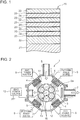
- a film deposition process by PVD for producing the above cutting tool 20 will be explained next with reference to Fig. 2 .
- the cutting tool 20 is produced using the film deposition apparatus 1 illustrated in Fig. 2 .
- the film deposition apparatus 1 is an apparatus for forming a coating film of a plurality of layers, by PVD, on the surface of a workpiece W which serves herein as the base material 21 of the cutting tool 20.
- the film deposition apparatus 1 illustrated in Fig. 2 comprises a vacuum chamber 2, a rotating table 3 on which workpieces W are placed, a plurality (two in Fig. 2 ) of arc evaporation sources 4 and a plurality (two in Fig. 2 ) of sputtering evaporation sources 5.
- the vacuum chamber 2 has a space 2a in which there are accommodated the rotating table 3 and the workpieces W placed on the rotating table 3. During the film deposition process, the space 2a is kept in vacuum, or in a state near vacuum, by a vacuum pump not shown.
- an introduction section 6 for introducing, into the space 2a, gases necessary for the film deposition process, and a discharge section 7 through which gases after the film deposition process are discharged out of the space 2a.
- the rotating table 3 is disposed within the space 2a of the vacuum chamber 2. During the film deposition process, the rotating table 3 rotates about a central axis O, in a state where a plurality of workpieces W has been placed on the rotating table 3.
- the rotating table 3 may be further provided with rotating platforms on which the workpieces W are individually placed, such that each workpiece W can rotate on itself.
- the arc evaporation sources 4 are evaporation sources for performing arc ion plating (hereafter, AIP) on the workpieces W, in order to form the first layer 22 made up of titanium aluminum nitride.
- the arc evaporation sources 4 are, for instance, arc ion plating evaporation sources of cathode discharge type.
- the arc evaporation sources 4 are connected to the cathodes of arc power sources 8.
- the anodes of the arc power sources 8 are, for instance, connected to the vacuum chamber 2, but may be connected to some other member.
- Targets 12 of titanium-aluminum (TiAl) that constitutes the material for forming a film of titanium aluminum nitride are mounted on the arc evaporation sources 4.
- the first layer 22 can be formed using sputtering evaporation sources for performing sputtering, instead of using the arc evaporation sources 4.
- the sputtering evaporation sources are for instance evaporation sources for performing magnetron sputtering, more specifically dual magnetron sputtering (DMS).
- the sputtering evaporation sources 5 are evaporation sources for performing film deposition on the workpieces W by sputtering, in order to form layers other than the first layer 22, namely the barrier layer 23 made up of aluminum nitride and the second layer 24 made up of alumina.
- the sputtering evaporation sources 5 are, for instance, dual magnetron sputtering (DMS) evaporation sources.
- the cathodes of sputtering power sources 9 are connected to the sputtering evaporation sources 5.
- the anodes of the sputtering power sources 9 are, for instance, connected to the vacuum chamber 2, but may be connected to some other member.
- Targets 13 of aluminum which constitutes the material for depositing a film of aluminum nitride and alumina, are mounted on the sputtering evaporation sources 5.
- the barrier layer 23 and the second layer 24 can be formed using arc evaporation sources that perform AIP, instead of the sputtering evaporation sources 5.
- the workpieces W made up of tungsten carbide (WC) that constitutes the base material 21 of the cutting tool 20 are firstly placed on the rotating table 3.
- Air inside the space 2a of the vacuum chamber 2 is discharged out of the chamber by means of a vacuum pump not shown.
- bias voltage is applied to the workpieces W from a bias power source 10, across the rotating table 3.
- the rotating table 3 rotates in this state, with the workpieces W placed thereon.
- the workpieces W on the rotating table 3 are heated by a heater 11.
- the first layer 22 made up of titanium aluminum nitride (TiAlN) becomes formed on the surface of the workpieces W (i.e. on the base material 21) by AIP, using the arc evaporation sources 4.
- nitrogen gas is supplied through the introduction section 6 into the space 2a of the vacuum chamber 2.
- high current from the arc power sources 8 is applied to the arc evaporation sources 4.
- Arc discharge occurs thereupon between the anodes and the targets 12 of titanium-aluminum of the arc evaporation sources 4.
- the first layer 22 made up of titanium aluminum nitride becomes thus formed on the surface of the workpieces W.
- the barrier layer 23 made up of aluminum nitride (AlN) is formed on the first layer 22 of the workpieces W through dual magnetron sputtering (DMS); using the sputtering evaporation sources 5.
- argon and nitrogen gas are supplied through the introduction section 6 into the space 2a of the vacuum chamber 2.
- high voltage is applied from the sputtering power sources 9 to the sputtering evaporation sources 5.
- argon between the cathodes and the aluminum targets 13 of the sputtering evaporation sources 5 is excited into a plasma state, and the ionized argon strikes the targets 13.
- Aluminum particles fly thereupon off the targets 13 and become adhered on the workpieces W.
- the supplied nitrogen gas as well decomposes and ionizes within the argon plasma, and becomes deposited on the surface of the workpieces W together with the aluminum particles; the barrier layer 23 made up of aluminum nitride becomes formed as a result on the surface of the workpieces W.
- the second layer 24 made up of alumina is formed on the barrier layer 23 of the workpieces W through UBMS using the sputtering evaporation sources 5, similarly to the barrier layer 23.
- argon and oxygen gas are supplied into the vacuum chamber 2, and high voltage from the sputtering power sources 9 is applied to the sputtering evaporation sources 5.
- argon between the cathodes and the aluminum targets 13 of the sputtering evaporation sources 5 is excited into a plasma state, and the ionized argon strikes the targets 13. Aluminum particles fly thereupon off the targets 13 and become adhered to the workpieces W.
- the supplied oxygen gas as well decomposes and ionizes within the argon plasma, and becomes deposited on the surface of the workpieces W together with the aluminum particles; the second layer 24 made up of alumina becomes formed as a result on the surface of the workpieces W.
- the cutting tool 20 produced in accordance with the production method of the present embodiment has a multilayer coating film that includes the barrier layer 23, and hence no titanium oxide is generated at the interface of the first layer 22 and the second layer 24.
- adhesion of the multilayer coating film in the cutting tool 20 is improved, whereby peeling of the multilayer coating film is rendered unlikelier.
- the cutting tool 20 produced in accordance with the production method of the present embodiment undergoes no peeling at all for instance in a scratch test (test for assessing the degree of peeling of a coating film through pressing of a hard, sharp tip of diamond or the like against the coating film), also under conditions where peeling of the coating film occurs in a structure having a conventional multilayer coating film (i.e. multilayer structure having no barrier layer).
- the production method of the cutting tool 20 of the present embodiment explained above has the following characterizing features.
- the cutting tool 20 such as a drill or an end mill
- the tool for machining produced in accordance with the production method of the present invention is a tool for machining having formed thereon a coating film of a plurality of layers including a first layer containing a nitride or carbide of titanium and a second layer containing aluminum oxide.
- the production method of the present invention can be used also to produce tools for machining other than cutting tools, such as tools for grinding and polishing.
- the method for producing a tool for machining of the present embodiment is a method for producing a tool for machining in which a coating film of a plurality of layers is formed on a surface of a base material by physical vapor deposition, the method including: a first layer formation step of forming a first layer containing a nitride or carbide of titanium on the surface of the base material; a first barrier layer formation step of forming a barrier layer that covers a surface of the first layer; and a second layer formation step of forming a second layer containing aluminum oxide on a surface of the barrier layer.
- a first layer containing a nitride or carbide that contains titanium is formed on the surface of a base material by physical vapor deposition (PVD), and then the surface of the first layer is covered by a barrier layer.
- PVD physical vapor deposition
- the titanium in the first layer is not exposed to oxygen gas, being a material for generating the aluminum oxide of the second layer containing aluminum oxide (alumina), on the first layer, even upon formation of the second layer by PVD on the surface of the barrier layer. Therefore, no titanium oxide is generated on the surface of the first layer. This allows preventing defective adhesion of the coating film at the interface of the first layer containing Ti and the second layer containing alumina.
- the production method of the present embodiment can be used also in a case where a multilayer coating film is formed through alternate layering of the first layer and the second layer.
- the method further has a second barrier layer formation step of forming the barrier layer that covers a surface of the second layer after the second layer formation step; wherein a plurality of cycles each including the first layer formation step, the first barrier layer formation step, the second layer formation step and the second barrier layer formation step are continuously performed.
- the inventors discovered the following features relating to such a multilayer coating film. Specifically, the inventors found that under conditions whereby the tool is in a high-temperature atmosphere, oxygen might desorb from the alumina layer and react with Ti of the layer containing Ti, thereby giving rise to titanium oxide, also at the interface of the alumina layer and the layer containing Ti and that is positioned on the alumina layer, in a case where a multilayer coating film is formed through alternate layering of a layer containing Ti and a layer containing alumina, as in conventional multilayer coating films. Specifically, the inventors found that when forming the multilayer coating film, titanium oxide is generated at the interface with the alumina layer also on the upper and lower surface sides of the layer containing Ti.
- a barrier layer is formed before and after formation of the second layer, as a result of which it becomes possible to prevent generation of titanium oxide at the interface with the alumina layer on the upper and lower surface sides of the layer containing Ti.
- defective adhesion of the multilayer coating film on the surface of the base material can be prevented, and adhesion of the multilayer coating film can be improved.
- the barrier layer includes a nitride or carbide of a metal different from titanium. Decreases in hardness on the entire layered portion of the coating film can be thus suppressed since the barrier layer containing a nitride or carbide of a metal has high hardness. Further, the metal is different from titanium, which prevents the generation of titanium oxide at the interface of the barrier layer and the second layer. Accordingly, it becomes possible to prevent defective adhesion at the interface.
- the barrier layer includes a nitride or carbide of a metal including aluminum.
- the composition of the barrier layer containing aluminum is similar to that of the second layer containing aluminum; adhesion and affinity of the barrier layer and the second layer are further enhanced as a result.
- the barrier layer preferably comprises aluminum nitride.
- Aluminum is used as a target in a case where the barrier layer is formed by PVD.
- This aluminum can be used as a target in the formation, by PVD, of the second layer containing aluminum oxide. Accordingly, a shared aluminum target can be used in a case where the barrier layer and the second layer are formed by PVD. This allows reducing the size of the film deposition apparatus for performing PVD.
- the first layer includes titanium aluminum nitride in a case where the barrier layer includes a nitride or carbide of a metal including aluminum, as described above.
- the composition of the first layer is similar to that of the barrier layer containing aluminum, and accordingly adhesion and affinity of the first layer and the barrier layer are further enhanced as a result.
- the first layer, the barrier layer and the second layer all contain aluminum, and hence there are enhanced adhesion and affinity in the entire layered portion of the foregoing layers.
- the tool for machining of the present embodiment is characterized by being produced in accordance with the above production method.
- the barrier layer is interposed between the first layer and the second layer, and hence no titanium oxide is generated at the interface of the first layer and the second layer. As a result, this allows preventing defective adhesion of the coating film at the interface of the first layer containing Ti and the second layer containing alumina.
Landscapes
- Chemical & Material Sciences (AREA)
- Engineering & Computer Science (AREA)
- Mechanical Engineering (AREA)
- Chemical Kinetics & Catalysis (AREA)
- Materials Engineering (AREA)
- Metallurgy (AREA)
- Organic Chemistry (AREA)
- Cutting Tools, Boring Holders, And Turrets (AREA)
- Drilling Tools (AREA)
- Physical Vapour Deposition (AREA)
Applications Claiming Priority (2)
| Application Number | Priority Date | Filing Date | Title |
|---|---|---|---|
| JP2014115515A JP6242751B2 (ja) | 2014-06-04 | 2014-06-04 | 機械加工用工具の製造方法、および機械加工用工具 |
| PCT/JP2015/063047 WO2015186460A1 (ja) | 2014-06-04 | 2015-04-30 | 機械加工用工具の製造方法、および機械加工用工具 |
Publications (3)
| Publication Number | Publication Date |
|---|---|
| EP3153258A1 EP3153258A1 (en) | 2017-04-12 |
| EP3153258A4 EP3153258A4 (en) | 2017-12-27 |
| EP3153258B1 true EP3153258B1 (en) | 2021-01-06 |
Family
ID=54766538
Family Applications (1)
| Application Number | Title | Priority Date | Filing Date |
|---|---|---|---|
| EP15803141.9A Active EP3153258B1 (en) | 2014-06-04 | 2015-04-30 | Method for producing a tool for machining, and tool for machining |
Country Status (7)
| Country | Link |
|---|---|
| US (1) | US20170051391A1 (he) |
| EP (1) | EP3153258B1 (he) |
| JP (1) | JP6242751B2 (he) |
| KR (1) | KR20170004002A (he) |
| CN (1) | CN106457414B (he) |
| IL (1) | IL248612B (he) |
| WO (1) | WO2015186460A1 (he) |
Families Citing this family (3)
| Publication number | Priority date | Publication date | Assignee | Title |
|---|---|---|---|---|
| DE4015493C1 (en) | 1989-09-20 | 1991-05-23 | Mti-Mischtechnik Industrieanlagen Gmbh, 4937 Lage, De | Easily cleanable vertical mixer - has a removable cover over the container, the container being split into two halves where the upper can be lifted off the lower |
| CN114427079A (zh) * | 2021-12-15 | 2022-05-03 | 广东拓必拓科技股份有限公司 | 刀具表面的自洁抗菌耐磨防锈的pvd膜层的制备方法 |
| WO2025244588A1 (en) * | 2024-05-24 | 2025-11-27 | King Mongkut's Institute Of Technology Ladkrabang | Multilayer-structured aluminum nitride and aluminum oxide film coated product and production method thereof |
Family Cites Families (17)
| Publication number | Priority date | Publication date | Assignee | Title |
|---|---|---|---|---|
| JPS6033603B2 (ja) * | 1977-08-25 | 1985-08-03 | 日本特殊陶業株式会社 | 硬質層を被覆した高速切削用工具 |
| DE59008847D1 (de) * | 1989-11-22 | 1995-05-11 | Balzers Hochvakuum | Werkzeug oder Instrument mit einer verschleissresistenten Hartschicht zum Be- oder Verarbeiten von organischem Material. |
| CA2155164C (en) * | 1994-08-01 | 2001-07-10 | Satoru Kukino | Super hard composite material for tools |
| SE518151C2 (sv) | 1997-12-10 | 2002-09-03 | Sandvik Ab | Multiskiktbelagt skärverktyg |
| JP3443314B2 (ja) * | 1998-03-12 | 2003-09-02 | 日立ツール株式会社 | 被覆硬質工具 |
| JP4171099B2 (ja) * | 1998-04-24 | 2008-10-22 | 株式会社神戸製鋼所 | 耐摩耗性に優れる硬質皮膜 |
| US20010016273A1 (en) * | 1998-05-08 | 2001-08-23 | Krishnan Narasimhan | Multilayer cvd coated article and process for producing same |
| JP3985412B2 (ja) * | 2000-02-08 | 2007-10-03 | 三菱マテリアル株式会社 | 耐摩耗性のすぐれた表面被覆超硬合金製切削工具 |
| JP3580271B2 (ja) * | 2001-07-16 | 2004-10-20 | 三菱マテリアル神戸ツールズ株式会社 | 切粉滑り性にすぐれた表面被覆超硬合金製切削工具 |
| US6767627B2 (en) * | 2002-12-18 | 2004-07-27 | Kobe Steel, Ltd. | Hard film, wear-resistant object and method of manufacturing wear-resistant object |
| JP3853757B2 (ja) * | 2003-05-30 | 2006-12-06 | ユニオンツール株式会社 | 切削工具用硬質皮膜 |
| JP2005153095A (ja) * | 2003-11-27 | 2005-06-16 | Kyocera Corp | 表面被覆切削工具 |
| CN100419117C (zh) * | 2004-02-02 | 2008-09-17 | 株式会社神户制钢所 | 硬质叠层被膜、其制造方法及成膜装置 |
| US7967961B2 (en) * | 2004-08-30 | 2011-06-28 | Ulvac, Inc | Film forming apparatus |
| WO2012018063A1 (ja) * | 2010-08-04 | 2012-02-09 | 株式会社タンガロイ | 被覆工具 |
| CN103084598A (zh) * | 2011-10-31 | 2013-05-08 | 三菱综合材料株式会社 | 硬质包覆层发挥优异的耐崩刀性的表面包覆切削工具 |
| EP2604720A1 (en) * | 2011-12-14 | 2013-06-19 | Sandvik Intellectual Property Ab | Coated cutting tool and method of manufacturing the same |
-
2014
- 2014-06-04 JP JP2014115515A patent/JP6242751B2/ja active Active
-
2015
- 2015-04-30 US US15/308,321 patent/US20170051391A1/en not_active Abandoned
- 2015-04-30 KR KR1020167035115A patent/KR20170004002A/ko not_active Ceased
- 2015-04-30 WO PCT/JP2015/063047 patent/WO2015186460A1/ja not_active Ceased
- 2015-04-30 EP EP15803141.9A patent/EP3153258B1/en active Active
- 2015-04-30 CN CN201580029642.7A patent/CN106457414B/zh active Active
-
2016
- 2016-10-30 IL IL248612A patent/IL248612B/he active IP Right Grant
Non-Patent Citations (1)
| Title |
|---|
| XINYU WANG ET AL: "Mechanical Property and Processing Investigation of Pulsed Laser Deposited Al", MATERIALS, vol. 2004, 1 January 2004 (2004-01-01), pages 147 - 151, XP055474476, ISBN: 978-0-7918-4712-1, DOI: 10.1115/IMECE2004-61000 * |
Also Published As
| Publication number | Publication date |
|---|---|
| KR20170004002A (ko) | 2017-01-10 |
| EP3153258A1 (en) | 2017-04-12 |
| IL248612A0 (he) | 2017-01-31 |
| JP2015229204A (ja) | 2015-12-21 |
| CN106457414A (zh) | 2017-02-22 |
| IL248612B (he) | 2021-06-30 |
| US20170051391A1 (en) | 2017-02-23 |
| WO2015186460A1 (ja) | 2015-12-10 |
| EP3153258A4 (en) | 2017-12-27 |
| JP6242751B2 (ja) | 2017-12-06 |
| CN106457414B (zh) | 2019-04-30 |
Similar Documents
| Publication | Publication Date | Title |
|---|---|---|
| JP6222675B2 (ja) | 表面被覆切削工具、およびその製造方法 | |
| JP5730535B2 (ja) | 硬質皮膜形成部材および硬質皮膜の形成方法 | |
| KR20090068150A (ko) | 코팅된 절삭 공구를 제조하는 방법 및 그 절삭 공구 | |
| JP2009078351A (ja) | 被膜付き切削工具の製造方法 | |
| JPWO2014025057A1 (ja) | 被覆工具 | |
| JP2005042146A (ja) | 高耐摩耗性高硬度皮膜 | |
| US20140248100A1 (en) | Drill having a coating | |
| JPH07171706A (ja) | 被覆工具及び切断方法 | |
| EP3153258B1 (en) | Method for producing a tool for machining, and tool for machining | |
| EP2758561B1 (en) | Coated cutting tool | |
| CN101720362A (zh) | 具有多层金属氧化物涂层的工具和制备所述涂层工具的方法 | |
| JP2019507025A (ja) | 切削装置 | |
| WO2012057000A1 (ja) | 硬質皮膜形成部材および硬質皮膜の形成方法 | |
| JP5241538B2 (ja) | 切削工具 | |
| US12195837B2 (en) | Cutting tool with hard coating film formed thereon | |
| KR101727420B1 (ko) | 내마모성이 우수한 적층 피막 | |
| JP2006169614A (ja) | 金属複合ダイヤモンドライクカーボン(dlc)皮膜、その形成方法、及び摺動部材 | |
| JP5580906B2 (ja) | 被膜、切削工具および被膜の製造方法 | |
| KR20090005857A (ko) | 피증착물의 박막 증착 장치, 박막 증착 방법 및 이에 의해증착된 고속 가공용 공구 | |
| JP2005335040A (ja) | 表面被覆切削工具 | |
| JP4084678B2 (ja) | 表面被覆切削工具およびその製造方法 | |
| JP7240053B2 (ja) | 酸窒化超多層被膜からなるAlCr耐酸化耐摩耗性被膜、その被覆物及びその製法 | |
| JP5975342B2 (ja) | 表面被覆切削工具 | |
| RU2700344C1 (ru) | СПОСОБ УПРОЧНЕНИЯ РЕЖУЩЕГО ИНСТРУМЕНТА ОСАЖДЕНИЕМ МУЛЬТИСЛОЙНЫХ ПОКРЫТИЙ СИСТЕМЫ Ti - Al | |
| JP4916176B2 (ja) | 被覆部材 |
Legal Events
| Date | Code | Title | Description |
|---|---|---|---|
| STAA | Information on the status of an ep patent application or granted ep patent |
Free format text: STATUS: THE INTERNATIONAL PUBLICATION HAS BEEN MADE |
|
| PUAI | Public reference made under article 153(3) epc to a published international application that has entered the european phase |
Free format text: ORIGINAL CODE: 0009012 |
|
| STAA | Information on the status of an ep patent application or granted ep patent |
Free format text: STATUS: REQUEST FOR EXAMINATION WAS MADE |
|
| 17P | Request for examination filed |
Effective date: 20161109 |
|
| AK | Designated contracting states |
Kind code of ref document: A1 Designated state(s): AL AT BE BG CH CY CZ DE DK EE ES FI FR GB GR HR HU IE IS IT LI LT LU LV MC MK MT NL NO PL PT RO RS SE SI SK SM TR |
|
| AX | Request for extension of the european patent |
Extension state: BA ME |
|
| DAV | Request for validation of the european patent (deleted) | ||
| DAX | Request for extension of the european patent (deleted) | ||
| A4 | Supplementary search report drawn up and despatched |
Effective date: 20171129 |
|
| RIC1 | Information provided on ipc code assigned before grant |
Ipc: C23C 28/04 20060101ALI20171123BHEP Ipc: B23B 27/14 20060101AFI20171123BHEP Ipc: B23P 15/28 20060101ALI20171123BHEP Ipc: B23C 5/16 20060101ALI20171123BHEP Ipc: B23B 51/00 20060101ALI20171123BHEP Ipc: C23C 14/02 20060101ALI20171123BHEP |
|
| STAA | Information on the status of an ep patent application or granted ep patent |
Free format text: STATUS: EXAMINATION IS IN PROGRESS |
|
| 17Q | First examination report despatched |
Effective date: 20180518 |
|
| GRAP | Despatch of communication of intention to grant a patent |
Free format text: ORIGINAL CODE: EPIDOSNIGR1 |
|
| STAA | Information on the status of an ep patent application or granted ep patent |
Free format text: STATUS: GRANT OF PATENT IS INTENDED |
|
| INTG | Intention to grant announced |
Effective date: 20201005 |
|
| GRAS | Grant fee paid |
Free format text: ORIGINAL CODE: EPIDOSNIGR3 |
|
| GRAA | (expected) grant |
Free format text: ORIGINAL CODE: 0009210 |
|
| STAA | Information on the status of an ep patent application or granted ep patent |
Free format text: STATUS: THE PATENT HAS BEEN GRANTED |
|
| AK | Designated contracting states |
Kind code of ref document: B1 Designated state(s): AL AT BE BG CH CY CZ DE DK EE ES FI FR GB GR HR HU IE IS IT LI LT LU LV MC MK MT NL NO PL PT RO RS SE SI SK SM TR |
|
| REG | Reference to a national code |
Ref country code: GB Ref legal event code: FG4D |
|
| REG | Reference to a national code |
Ref country code: AT Ref legal event code: REF Ref document number: 1351824 Country of ref document: AT Kind code of ref document: T Effective date: 20210115 Ref country code: CH Ref legal event code: EP |
|
| REG | Reference to a national code |
Ref country code: DE Ref legal event code: R096 Ref document number: 602015064494 Country of ref document: DE |
|
| REG | Reference to a national code |
Ref country code: IE Ref legal event code: FG4D |
|
| REG | Reference to a national code |
Ref country code: NL Ref legal event code: MP Effective date: 20210106 |
|
| REG | Reference to a national code |
Ref country code: AT Ref legal event code: MK05 Ref document number: 1351824 Country of ref document: AT Kind code of ref document: T Effective date: 20210106 |
|
| REG | Reference to a national code |
Ref country code: LT Ref legal event code: MG9D |
|
| PG25 | Lapsed in a contracting state [announced via postgrant information from national office to epo] |
Ref country code: LT Free format text: LAPSE BECAUSE OF FAILURE TO SUBMIT A TRANSLATION OF THE DESCRIPTION OR TO PAY THE FEE WITHIN THE PRESCRIBED TIME-LIMIT Effective date: 20210106 Ref country code: PT Free format text: LAPSE BECAUSE OF FAILURE TO SUBMIT A TRANSLATION OF THE DESCRIPTION OR TO PAY THE FEE WITHIN THE PRESCRIBED TIME-LIMIT Effective date: 20210506 Ref country code: NO Free format text: LAPSE BECAUSE OF FAILURE TO SUBMIT A TRANSLATION OF THE DESCRIPTION OR TO PAY THE FEE WITHIN THE PRESCRIBED TIME-LIMIT Effective date: 20210406 Ref country code: BG Free format text: LAPSE BECAUSE OF FAILURE TO SUBMIT A TRANSLATION OF THE DESCRIPTION OR TO PAY THE FEE WITHIN THE PRESCRIBED TIME-LIMIT Effective date: 20210406 Ref country code: NL Free format text: LAPSE BECAUSE OF FAILURE TO SUBMIT A TRANSLATION OF THE DESCRIPTION OR TO PAY THE FEE WITHIN THE PRESCRIBED TIME-LIMIT Effective date: 20210106 Ref country code: HR Free format text: LAPSE BECAUSE OF FAILURE TO SUBMIT A TRANSLATION OF THE DESCRIPTION OR TO PAY THE FEE WITHIN THE PRESCRIBED TIME-LIMIT Effective date: 20210106 Ref country code: GR Free format text: LAPSE BECAUSE OF FAILURE TO SUBMIT A TRANSLATION OF THE DESCRIPTION OR TO PAY THE FEE WITHIN THE PRESCRIBED TIME-LIMIT Effective date: 20210407 Ref country code: FI Free format text: LAPSE BECAUSE OF FAILURE TO SUBMIT A TRANSLATION OF THE DESCRIPTION OR TO PAY THE FEE WITHIN THE PRESCRIBED TIME-LIMIT Effective date: 20210106 |
|
| PG25 | Lapsed in a contracting state [announced via postgrant information from national office to epo] |
Ref country code: SE Free format text: LAPSE BECAUSE OF FAILURE TO SUBMIT A TRANSLATION OF THE DESCRIPTION OR TO PAY THE FEE WITHIN THE PRESCRIBED TIME-LIMIT Effective date: 20210106 Ref country code: LV Free format text: LAPSE BECAUSE OF FAILURE TO SUBMIT A TRANSLATION OF THE DESCRIPTION OR TO PAY THE FEE WITHIN THE PRESCRIBED TIME-LIMIT Effective date: 20210106 Ref country code: PL Free format text: LAPSE BECAUSE OF FAILURE TO SUBMIT A TRANSLATION OF THE DESCRIPTION OR TO PAY THE FEE WITHIN THE PRESCRIBED TIME-LIMIT Effective date: 20210106 Ref country code: RS Free format text: LAPSE BECAUSE OF FAILURE TO SUBMIT A TRANSLATION OF THE DESCRIPTION OR TO PAY THE FEE WITHIN THE PRESCRIBED TIME-LIMIT Effective date: 20210106 Ref country code: AT Free format text: LAPSE BECAUSE OF FAILURE TO SUBMIT A TRANSLATION OF THE DESCRIPTION OR TO PAY THE FEE WITHIN THE PRESCRIBED TIME-LIMIT Effective date: 20210106 |
|
| PG25 | Lapsed in a contracting state [announced via postgrant information from national office to epo] |
Ref country code: IS Free format text: LAPSE BECAUSE OF FAILURE TO SUBMIT A TRANSLATION OF THE DESCRIPTION OR TO PAY THE FEE WITHIN THE PRESCRIBED TIME-LIMIT Effective date: 20210506 |
|
| REG | Reference to a national code |
Ref country code: DE Ref legal event code: R097 Ref document number: 602015064494 Country of ref document: DE |
|
| PG25 | Lapsed in a contracting state [announced via postgrant information from national office to epo] |
Ref country code: CZ Free format text: LAPSE BECAUSE OF FAILURE TO SUBMIT A TRANSLATION OF THE DESCRIPTION OR TO PAY THE FEE WITHIN THE PRESCRIBED TIME-LIMIT Effective date: 20210106 Ref country code: EE Free format text: LAPSE BECAUSE OF FAILURE TO SUBMIT A TRANSLATION OF THE DESCRIPTION OR TO PAY THE FEE WITHIN THE PRESCRIBED TIME-LIMIT Effective date: 20210106 Ref country code: SM Free format text: LAPSE BECAUSE OF FAILURE TO SUBMIT A TRANSLATION OF THE DESCRIPTION OR TO PAY THE FEE WITHIN THE PRESCRIBED TIME-LIMIT Effective date: 20210106 |
|
| PLBE | No opposition filed within time limit |
Free format text: ORIGINAL CODE: 0009261 |
|
| STAA | Information on the status of an ep patent application or granted ep patent |
Free format text: STATUS: NO OPPOSITION FILED WITHIN TIME LIMIT |
|
| PG25 | Lapsed in a contracting state [announced via postgrant information from national office to epo] |
Ref country code: RO Free format text: LAPSE BECAUSE OF FAILURE TO SUBMIT A TRANSLATION OF THE DESCRIPTION OR TO PAY THE FEE WITHIN THE PRESCRIBED TIME-LIMIT Effective date: 20210106 Ref country code: SK Free format text: LAPSE BECAUSE OF FAILURE TO SUBMIT A TRANSLATION OF THE DESCRIPTION OR TO PAY THE FEE WITHIN THE PRESCRIBED TIME-LIMIT Effective date: 20210106 Ref country code: MC Free format text: LAPSE BECAUSE OF FAILURE TO SUBMIT A TRANSLATION OF THE DESCRIPTION OR TO PAY THE FEE WITHIN THE PRESCRIBED TIME-LIMIT Effective date: 20210106 Ref country code: DK Free format text: LAPSE BECAUSE OF FAILURE TO SUBMIT A TRANSLATION OF THE DESCRIPTION OR TO PAY THE FEE WITHIN THE PRESCRIBED TIME-LIMIT Effective date: 20210106 Ref country code: ES Free format text: LAPSE BECAUSE OF FAILURE TO SUBMIT A TRANSLATION OF THE DESCRIPTION OR TO PAY THE FEE WITHIN THE PRESCRIBED TIME-LIMIT Effective date: 20210106 |
|
| 26N | No opposition filed |
Effective date: 20211007 |
|
| GBPC | Gb: european patent ceased through non-payment of renewal fee |
Effective date: 20210430 |
|
| PG25 | Lapsed in a contracting state [announced via postgrant information from national office to epo] |
Ref country code: LU Free format text: LAPSE BECAUSE OF NON-PAYMENT OF DUE FEES Effective date: 20210430 |
|
| REG | Reference to a national code |
Ref country code: BE Ref legal event code: MM Effective date: 20210430 |
|
| PG25 | Lapsed in a contracting state [announced via postgrant information from national office to epo] |
Ref country code: GB Free format text: LAPSE BECAUSE OF NON-PAYMENT OF DUE FEES Effective date: 20210430 Ref country code: FR Free format text: LAPSE BECAUSE OF NON-PAYMENT OF DUE FEES Effective date: 20210430 Ref country code: AL Free format text: LAPSE BECAUSE OF FAILURE TO SUBMIT A TRANSLATION OF THE DESCRIPTION OR TO PAY THE FEE WITHIN THE PRESCRIBED TIME-LIMIT Effective date: 20210106 Ref country code: CH Free format text: LAPSE BECAUSE OF NON-PAYMENT OF DUE FEES Effective date: 20210430 Ref country code: LI Free format text: LAPSE BECAUSE OF NON-PAYMENT OF DUE FEES Effective date: 20210430 |
|
| PG25 | Lapsed in a contracting state [announced via postgrant information from national office to epo] |
Ref country code: SI Free format text: LAPSE BECAUSE OF FAILURE TO SUBMIT A TRANSLATION OF THE DESCRIPTION OR TO PAY THE FEE WITHIN THE PRESCRIBED TIME-LIMIT Effective date: 20210106 |
|
| PG25 | Lapsed in a contracting state [announced via postgrant information from national office to epo] |
Ref country code: IT Free format text: LAPSE BECAUSE OF FAILURE TO SUBMIT A TRANSLATION OF THE DESCRIPTION OR TO PAY THE FEE WITHIN THE PRESCRIBED TIME-LIMIT Effective date: 20210106 Ref country code: IE Free format text: LAPSE BECAUSE OF NON-PAYMENT OF DUE FEES Effective date: 20210430 |
|
| PG25 | Lapsed in a contracting state [announced via postgrant information from national office to epo] |
Ref country code: IS Free format text: LAPSE BECAUSE OF FAILURE TO SUBMIT A TRANSLATION OF THE DESCRIPTION OR TO PAY THE FEE WITHIN THE PRESCRIBED TIME-LIMIT Effective date: 20210506 |
|
| PG25 | Lapsed in a contracting state [announced via postgrant information from national office to epo] |
Ref country code: BE Free format text: LAPSE BECAUSE OF NON-PAYMENT OF DUE FEES Effective date: 20210430 |
|
| PG25 | Lapsed in a contracting state [announced via postgrant information from national office to epo] |
Ref country code: HU Free format text: LAPSE BECAUSE OF FAILURE TO SUBMIT A TRANSLATION OF THE DESCRIPTION OR TO PAY THE FEE WITHIN THE PRESCRIBED TIME-LIMIT; INVALID AB INITIO Effective date: 20150430 |
|
| P01 | Opt-out of the competence of the unified patent court (upc) registered |
Effective date: 20230523 |
|
| PG25 | Lapsed in a contracting state [announced via postgrant information from national office to epo] |
Ref country code: CY Free format text: LAPSE BECAUSE OF FAILURE TO SUBMIT A TRANSLATION OF THE DESCRIPTION OR TO PAY THE FEE WITHIN THE PRESCRIBED TIME-LIMIT Effective date: 20210106 |
|
| PG25 | Lapsed in a contracting state [announced via postgrant information from national office to epo] |
Ref country code: MK Free format text: LAPSE BECAUSE OF FAILURE TO SUBMIT A TRANSLATION OF THE DESCRIPTION OR TO PAY THE FEE WITHIN THE PRESCRIBED TIME-LIMIT Effective date: 20210106 |
|
| PG25 | Lapsed in a contracting state [announced via postgrant information from national office to epo] |
Ref country code: TR Free format text: LAPSE BECAUSE OF FAILURE TO SUBMIT A TRANSLATION OF THE DESCRIPTION OR TO PAY THE FEE WITHIN THE PRESCRIBED TIME-LIMIT Effective date: 20210106 |
|
| PG25 | Lapsed in a contracting state [announced via postgrant information from national office to epo] |
Ref country code: MT Free format text: LAPSE BECAUSE OF FAILURE TO SUBMIT A TRANSLATION OF THE DESCRIPTION OR TO PAY THE FEE WITHIN THE PRESCRIBED TIME-LIMIT Effective date: 20210106 |
|
| PGFP | Annual fee paid to national office [announced via postgrant information from national office to epo] |
Ref country code: DE Payment date: 20250305 Year of fee payment: 11 |