EP3153087A1 - Geschirrspülmaschine - Google Patents
Geschirrspülmaschine Download PDFInfo
- Publication number
- EP3153087A1 EP3153087A1 EP16192175.4A EP16192175A EP3153087A1 EP 3153087 A1 EP3153087 A1 EP 3153087A1 EP 16192175 A EP16192175 A EP 16192175A EP 3153087 A1 EP3153087 A1 EP 3153087A1
- Authority
- EP
- European Patent Office
- Prior art keywords
- illumination device
- lighting device
- dishwasher
- dishwasher according
- washing
- Prior art date
- Legal status (The legal status is an assumption and is not a legal conclusion. Google has not performed a legal analysis and makes no representation as to the accuracy of the status listed.)
- Granted
Links
Images


Classifications
-
- A—HUMAN NECESSITIES
- A47—FURNITURE; DOMESTIC ARTICLES OR APPLIANCES; COFFEE MILLS; SPICE MILLS; SUCTION CLEANERS IN GENERAL
- A47L—DOMESTIC WASHING OR CLEANING; SUCTION CLEANERS IN GENERAL
- A47L15/00—Washing or rinsing machines for crockery or tableware
- A47L15/42—Details
- A47L15/4246—Details of the tub
-
- A—HUMAN NECESSITIES
- A47—FURNITURE; DOMESTIC ARTICLES OR APPLIANCES; COFFEE MILLS; SPICE MILLS; SUCTION CLEANERS IN GENERAL
- A47L—DOMESTIC WASHING OR CLEANING; SUCTION CLEANERS IN GENERAL
- A47L15/00—Washing or rinsing machines for crockery or tableware
- A47L15/42—Details
- A47L15/4251—Details of the casing
Definitions
- the invention relates to a dishwasher, in particular a domestic dishwasher, with a washing compartment providing a washing compartment, which serves to receive items to be cleaned, wherein the washing container for loading with items has a feed opening, which is fluid-tightly closed by means of a rotatably mounted Spülraumt, and with a arranged outside the washing compartment lighting device.
- Dishwashers of the generic type have a washing compartment providing a washing compartment. This is the user side accessible via a feed opening, which is fluid-tightly closed by means of a pivotally mounted washroom door.
- the washing container serves to receive items to be cleaned, which may be dishes, cutlery pieces and / or the like, for example.
- the dishwasher For loading of items to be cleaned with rinsing liquid, the so-called rinsing liquor, the dishwasher has a spray device in the interior of the washing container.
- This spraying device typically provides rotatably mounted spray arms, wherein usually two or three such spray arms are provided.
- a loading of the items to be cleaned with rinse liquor by means of rotating spray arms.
- a light source in the washing compartment provided by the washing compartment.
- This light source can be switched by means of a door-operated circuit arrangement, so that when the dishwasher door is pivoted from the closed position into an open position, the light source is automatically switched on. Since this light source is used to illuminate the washroom, it is also referred to as washroom lighting.
- the arrangement of a light source within the washing compartment can be disadvantageous in that the user is dazzled in the intended use case.
- a lighting device is for example from the DE 10 2004 051 174 A1 according to which the lighting device is formed on the pivotally arranged Spülraumt.
- the embodiment of the DE 10 2004 051 174 A1 is not free from disadvantages.
- the EP 2 394 557 A2 has been proposed to arrange the lighting device at the top of the feed opening.
- Advantage of this solution is that a sufficient illumination of an extended lower and / or upper basket is possible. However, it can only take place an insufficient illumination of the washing itself.
- a light guiding device which, for example by means of a lens, at least partially diverts the light emitted by the lighting device into the washing compartment.
- the object of the invention to further develop a dishwasher to the effect that an improved illumination in particular of the washing compartment is allowed.
- the invention proposes a dishwasher of the type mentioned, which is characterized in that the lighting device is arranged movably on the washing.
- the illumination device provided according to the invention is adjustable in its relative position to the washing container, it can therefore be transferred from a position of use to a non-use position and vice versa.
- This embodiment of the invention makes it possible to convert the lighting device in case of need in their position of use, in which position an optimized illumination of the washing compartment is allowed. Despite such an optimized Spülraumausbeleuchtung no larger installation space is required, since due to the movable arrangement of the lighting device in relation to the washing a transferring the same is allowed in a non-use position. In the non-use position, the lighting device is not functional and saves space.
- the lighting device preferably has an abutment which cooperates with the Spülraumt.
- the abutment may be, for example, a contact surface which, in the event of movement of the illumination device, rests on the inside of the flushing chamber door. A transfer of the lighting device from a non-use position to a use position and vice versa can therefore be achieved depending on the Spülraumtscher.
- the lighting device is in the open position when the dishwasher door is open.
- it can be provided to place the lighting device under spring action, so that this moves spring-loaded in its intended use position.
- such a method is only possible with the dishwasher door open, as this otherwise blocks movement of the lighting device.
- the lighting device is automatically transferred to its position of use in a spring-loaded condition. Once the Spülraumt closed again, that is spent from its open position to its closed position, moves the Spülraumt with its inside wall on the lighting device and counteracts the spring force acting on the lighting device a back process also the lighting device in its non-use position.
- the lighting device switches off, which ensures that the lighting device is switched off when the washroom door is closed. Accordingly, an automatic switching on of the lighting device takes place when the lighting device is transferred as a result of a transfer of the Spülraumt in an open position from the non-use position into a position of use.
- the lighting device is formed linearly movable. It can therefore be moved in a straight line.
- a rotatable embodiment of the illumination device may be provided, in which case the illumination device is rotated about a fixed pivot point. In both cases, it may be provided in the manner already described above that the illumination device moves from a non-use position into a use position or rotates and vice versa.
- the illumination device is accommodated within a housing arranged on the rinsing container.
- This housing may for example be arranged at the edge upper side of the charging opening of the washing container on the washing compartment.
- the housing or the illumination device is positioned on the rinsing container in such a way that, in the case of use, a co-operation of the rinsing chamber door with the illumination device can take place. It then requires no further switching devices, since an operation of the lighting device is automatically accompanied by a pivoting of the dishwasher door.
- the illumination device can according to a further feature of the invention have a light source.
- a light source Preferably, an LED is provided as the light source.
- a corresponding wiring can be provided or it is the formation of contact rails possible.
- the power supply is in any case designed such that the above-described movement of the lighting device from a non-use position is allowed in a use position and vice versa.
- the lighting device at least water-repellent, so that it can not be due to splashing water and / or vapors to damage the lighting device.
- a watertight embodiment of the lighting device is not necessary, since it is not arranged inside the washing compartment but outside it.
- the illumination device does not have a light source, but it is provided that a light guide opens into the illumination device.
- the light source is positioned independently of the illumination device and the light generated by it is conveyed by means of a light guide to the illumination device. The lighting device is thus formed at the end of the light guide.
- a dishwasher is proposed as a whole, which, in contrast to the prior art, permits improved illumination, in particular of the washing container, that is to say the washing compartment provided by the washing container.
- the lighting device is designed to be movable and can be moved from a non-use position into a use position, in which position the relative position of the lighting device to the washing compartment is such that illumination is possible over an enlarged angular range in contrast to the prior art.
- shadowing caused by the charging port-side purge door seal is minimized.
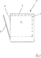
- Fig. 1 can be seen in a purely schematic representation of a dishwasher 1 according to the invention.
- This has, in a manner known per se, a housing 2 accommodating a washing container 3, which in turn defines a washing compartment 4.
- the washing compartment 4 is accessible via a charging opening 5, which can be closed by means of a pivotally mounted flushing door 6.
- Fig. 1 shows the Spülraumt 6 in the half-open position.
- the dishwasher 1 For illumination, in particular also of the washing compartment 4, the dishwasher 1 has a lighting device 7.
- Fig. 2 schematically identifies possible positions X for such a lighting device 7, wherein the use of multiple lighting devices 7 is possible.
- FIGS. 3 to 8 shows an embodiment according to which the dishwasher 1 has an illumination device 7, which is arranged in the region of the upper end edge of the feed opening 5.
- This factual context is in particular the case FIGS. 3, 4 and 5 recognize in their synopsis.
- the lighting device 7 is arranged linearly movable on the washing container 3.
- a housing 11 is provided, in which the interposition of a spring 12, the lighting device 7 is housed.
- the illumination device 7 provides a contact surface 13 on the side of the flushing chamber, which interacts on the inside of the flushing chamber door 6 with a peripheral edge 10 of the flushing chamber door 6, as shown in FIGS FIGS. 4 and 5 reveal.
- Fig. 4 shows the Spülraumt 6 in the closed position.
- the feed opening 5 is closed fluid-tight, which is achieved in that the Spülraumt 6 rests with its inner side 9 to a circumferential door seal 8.
- the lighting device 7 is in this position of the Spülraumt 6 in its non-use position and is turned off.
- the Spülraumt 6 is opened, which is in Fig. 5 is shown, it pivots with respect to the plane of the drawing Fig. 5 to the right, that is in the direction of the arrow. Due to the spring force acting on the illumination device 7, the illumination device 7 is moved linearly relative to the housing 11 and thus also relative to the rinsing container 3, in the direction of the arrow. In the extended position of the lighting device 7, as this in Fig. 5 is shown, selbige is in the use position and is turned on. In this position of use, an optimized illumination of the washing compartment 4 takes place by means of the lighting device 7 located in the position of use.
- Fig. 6 shows the rinse tank 3 and the provided therefrom Spülraum 4 schematically in a side view with the Spülraumt 6.
- the lighting device 7 is formed in the region of the upper peripheral edge of the feed opening 6.
- Fig. 7 shows the detail B according to an embodiment of the prior art. According to this, an illumination device 7 with light distribution device in the form of a lens is used. As can be seen from this illustration, the possible angle of incidence ⁇ 1 is limited by the seal 8 on the flushing chamber side. It turns so far as a corresponding shading.
- Fig. 8 shows the embodiment of the invention.
- the angle of incidence ⁇ 2 increases considerably, namely because the illumination device 7 is illuminated from the non-use position in order to illuminate the flushing space 4 Fig. 4 in the position of use Fig. 5 procedure is.
- the shading caused by the seal 8 is significantly reduced due to the increased light incidence angle ⁇ 2 , which leads to the advantage of a significantly improved illumination of the washing compartment 4.
- FIGS. 9, 10 and 11 show an alternative embodiment.
- the illumination device 7 is not linearly movable, but designed to pivot about a fixed pivot point 14.
- the operation is the same as already explained with reference to the preceding figures, since the illumination device 7 from a non-use position ( Fig. 9 ) in a position of use ( Fig. 10 ) and vice versa.
- the illumination device 7 cooperates with the Spülraumt 6, so that when opening the Spülraumt 6 a transfer of the illumination device 7 takes place automatically in the use position.
- a pivotable trained lighting device 7 this is preferably done by spring force.
- an electromotive method of the illumination device 7 is of course conceivable, both in a movable and in a rotatable arrangement of the illumination device. 7
Landscapes
- Washing And Drying Of Tableware (AREA)
Abstract
Description
- Die Erfindung betrifft eine Geschirrspülmaschine, insbesondere eine Haushaltsgeschirrspülmaschine, mit einem einen Spülraum bereitstellenden Spülbehälter, der der Aufnahme von zu reinigendem Spülgut dient, wobei der Spülbehälter zur Beschickung mit Spülgut eine Beschickungsöffnung aufweist, die mittels einer verdrehbar gelagerten Spülraumtür fluiddicht verschließbar ist, sowie mit einer außerhalb des Spülraums angeordnete Beleuchtungseinrichtung.
- Geschirrspülmaschinen der gattungsgemäßen Art verfügen über einen einen Spülraum bereitstellenden Spülbehälter. Dieser ist verwenderseitig über eine Beschickungsöffnung zugänglich, die mittels einer verschwenkbar gelagerten Spülraumtür fluiddicht verschließbar ist. Im bestimmungsgemäßen Verwendungsfall dient der Spülbehälter der Aufnahme von zu reinigendem Spülgut, bei dem es sich beispielsweise um Geschirr, Besteckteile und/oder dergleichen handeln kann.
- Zur Beaufschlagung von zu reinigendem Spülgut mit Spülflüssigkeit, der sogenannten Spülflotte, verfügt die Geschirrspülmaschine im Innenraum des Spülbehälters über eine Sprüheinrichtung. Diese Sprüheinrichtung stellt typischerweise verdrehbar gelagerte Sprüharme zur Verfügung, wobei in der Regel zwei oder drei solcher Sprüharme vorgesehen sind. Im bestimmungsgemäßen Verwendungsfall erfolgt eine Beaufschlagung des zu reinigenden Spülguts mit Spülflotte mittels sich drehender Sprüharme.
- Um einem Verwender eine Beschickung und/oder Entleerung der Geschirrspülmaschine zu erleichtern, ist es aus dem Stand der Technik bekannt, in dem vom Spülbehälter bereitgestellten Spülraum eine Lichtquelle anzuordnen. Diese Lichtquelle ist mittels einer türbetätigten Schaltungsanordnung schaltbar, so dass bei einem Verschwenken der Spülraumtür aus der Verschlussstellung in eine Offenstellung ein automatisches Einschalten der Lichtquelle stattfindet. Da diese Lichtquelle der Ausleuchtung des Spülraums dient, wird sie auch als Spülraumbeleuchtung bezeichnet.
- Die Anordnung einer Lichtquelle innerhalb des Spülraums kann insofern von Nachteil sein, als dass der Verwender im bestimmungsgemäßen Verwendungsfall geblendet wird. Um diesem Nachteil zu begegnen, ist es aus dem Stand der Technik bekannt geworden, eine Geschirrspülmaschine mit einer außerhalb des Spülraums angeordnete Beleuchtungseinrichtung auszurüsten. Eine derartige Beleuchtungseinrichtung ist beispielsweise aus der
DE 10 2004 051 174 A1 bekannt, dergemäß die Beleuchtungseinrichtung an der verschwenkbar angeordneten Spülraumtür ausgebildet ist. - Die Ausgestaltung nach der
DE 10 2004 051 174 A1 ist allerdings nicht frei von Nachteilen. So ist insbesondere problematisch, dass bei einem bestimmungsgemäß ausgezogenen Unterkorb die Beleuchtungseinrichtung vom Unterkorb verdeckt ist, so dass eine hinreichende Ausleuchtung des Spülraums nicht mehr gewährleistet ist. Um diesem Problem zu begegnen, ist mit derEP 2 394 557 A2 vorgeschlagen worden, die Beleuchtungseinrichtung am oberen Rand der Beschickungsöffnung anzuordnen. Vorteil dieser Lösung ist, dass eine hinreichende Ausleuchtung eines ausgezogenen Unter- und/oder Oberkorbs möglich ist. Es kann allerdings nur eine unzureichende Ausleuchtung des Spülraums selbst stattfinden. Um gleichwohl einen Teil des von der Beleuchtungseinrichtung abgegebenen Lichts in den vom Spülbehälter bereitgestellten Spülraum abzugeben, kommt eine Lichtleitvorrichtung zum Einsatz, die beispielsweise mittels einer Linse das von der Beleuchtungseinrichtung abgegebene Licht zumindest teilweise in den Spülraum umlenkt. - Obgleich sich die vorbeschriebene Beleuchtungseinrichtung im alltäglichen Praxiseinsatz bewährt hat, ist diese nicht frei von Nachteilen. So erfordert ein aus der
EP 2 394 557 A2 bekanntes Beleuchtungssystem einen entsprechenden Einbauraum randseitig der Beschickungsöffnung. Dieser Einbauraum steht aber nicht immer zur Verfügung, insbesondere dann nicht, wenn die Geschirrspülmaschine als sogenannte vollintegrierte Maschine ausgebildet ist, bei der die verwenderseitig zu erreichenden Bedienelemente stirnseitig der Spülraumtür angeordnet sind. Im Übrigen ist bei der vorbekannten Konstruktion von Nachteil, dass trotz der vorgesehenen Lichtleitvorrichtung eine nur unzureichende Spülraumausleuchtung gestattet ist, da die im Türzargenbereich angeordnete Türdichtung für eine Schattenbildung innerhalb des Spülraums sorgt. - Es ist zur Vermeidung der voraufgeführten Nachteile die Aufgabe der Erfindung, eine Geschirrspülmaschine dahingehend weiterzuentwickeln, dass eine verbesserte Ausleuchtung insbesondere auch des Spülraums gestattet ist.
- Zur Lösung dieser Aufgabe wird mit der Erfindung eine Geschirrspülmaschine der eingangs genannten Art vorgeschlagen, die sich dadurch auszeichnet, dass die Beleuchtungseinrichtung am Spülbehälter bewegbar angeordnet ist.
- Die nach der Erfindung vorgesehene Beleuchtungseinrichtung ist in ihrer relativen Lage zum Spülbehälter verstellbar, sie kann mithin aus einer Gebrauchsstellung in eine Nicht-Gebrauchsstellung überführt werden und umgekehrt. Diese erfindungsgemäße Ausgestaltung gestattet es, die Beleuchtungseinrichtung im Bedarfsfall in ihre Gebrauchsstellung zu überführen, in welcher Stellung eine optimierte Ausleuchtung des Spülraums gestattet ist. Trotz einer solchen optimierten Spülraumausleuchtung ist kein größerer Einbauraum erforderlich, da aufgrund der bewegbaren Anordnung der Beleuchtungseinrichtung in Relation zum Spülbehälter ein Überführen derselben in eine Nicht-Gebrauchsstellung gestattet ist. In der Nicht-Gebrauchsstellung ist die Beleuchtungseinrichtung nicht in Funktion und platzsparend untergebracht.
- Die Beleuchtungseinrichtung verfügt bevorzugterweise über ein Widerlager, das mit der Spülraumtür zusammenwirkt. Bei dem Widerlager kann es sich beispielsweise um eine Kontaktfläche handeln, die im Bewegungsfall der Beleuchtungseinrichtung innenseitig der Spülraumtür anliegt. Ein Überführen der Beleuchtungseinrichtung aus einer Nicht-Gebrauchsstellung in eine Gebrauchsstellung und umgekehrt kann mithin in Abhängigkeit der Spülraumtürstellung erreicht werden.
- Es ist indes bevorzugt, dass sich die Beleuchtungseinrichtung bei geöffneter Spülraumtür in Gebrauchsstellung befindet. Zu diesem Zweck kann vorgesehen sein, die Beleuchtungseinrichtung unter Federeinwirkung zu stellen, so dass diese federbelastet in ihre bestimmungsgemäße Gebrauchsstellung verfährt. Ein solches Verfahren ist allerdings nur bei geöffneter Spülraumtür möglich, da diese ansonsten eine Bewegung der Beleuchtungseinrichtung blockiert. So kann beispielsweise vorgesehen sein, dass bei einem Öffnen der Spülraumtür die Beleuchtungseinrichtung federbelastet bedingt automatisch in ihre Gebrauchsstellung überführt wird. Sobald die Spülraumtür wieder geschlossen, das heißt aus ihrer Offenstellung in ihre Verschlussstellung verbracht wird, fährt die Spülraumtür mit ihrer innenseitigen Wandung auf die Beleuchtungseinrichtung auf und bewirkt entgegen der auf die Beleuchtungseinrichtung einwirkenden Federkraft ein Zurückverfahren auch der Beleuchtungseinrichtung in ihre Nicht-Gebrauchsstellung.
- Sobald die Beleuchtungseinrichtung ihre Nicht-Gebrauchsstellung erreicht hat, schaltet sich die Beleuchtungseinrichtung aus, womit sichergestellt ist, dass die Beleuchtungseinrichtung bei geschlossener Spülraumtür ausgeschaltet ist. Dementsprechend findet ein automatisches Einschalten der Beleuchtungseinrichtung statt, wenn die Beleuchtungseinrichtung infolge einer Überführung der Spülraumtür in eine Offenstellung aus der Nicht-Gebrauchsstellung in eine Gebrauchsstellung überführt wird.
- Gemäß einer ersten Alternative der Erfindung ist die Beleuchtungseinrichtung linear verfahrbar ausgebildet. Sie kann mithin gradlinig verfahren werden. Alternativ kann eine verdrehbare Ausgestaltung der Beleuchtungseinrichtung vorgesehen sein, in welchem Fall die Beleuchtungseinrichtung um einen feststehenden Drehpunkt verdreht. In beiden Fällen kann in der schon vorbeschriebenen Weise vorgesehen sein, dass die Beleuchtungseinrichtung aus einer Nicht-Gebrauchsstellung in eine Gebrauchsstellung verfährt beziehungsweise verdreht und umgekehrt.
- Konstruktiv kann gemäß einem weiteren Merkmal der Erfindung vorgesehen sein, dass die Beleuchtungseinrichtung innerhalb eines am Spülbehälter angeordneten Gehäuses untergebracht ist. Dieses Gehäuse kann beispielsweise randoberseitig der Beschickungsöffnung des Spülbehälters am Spülbehälter angeordnet sein. Bei geöffneter Spülraumtür befindet sich die Beleuchtungseinrichtung in ihrer Gebrauchsstellung, in welcher sie die obere Randkante der Beschickungsöffnung je nach zugelassenem Verfahrweg überragt, so dass im Unterschied zum Stand der Technik ein tieferes Ausleuchten des Spülraums gestattet ist. Dabei ist das Gehäuse beziehungsweise die Beleuchtungseinrichtung am Spülbehälter derart positioniert, dass im Verwendungsfall ein Zusammenwirken der Spülraumtür mit der Beleuchtungseinrichtung stattfinden kann. Es bedarf dann keiner weiteren Schalteinrichtungen, da eine Bedienung der Beleuchtungseinrichtung automatisch mit einer Verschwenkung der Spülraumtür einhergeht.
- Die Beleuchtungseinrichtung kann gemäß einem weiteren Merkmal der Erfindung über eine Lichtquelle verfügen. Bevorzugterweise ist eine LED als Lichtquelle vorgesehen. Zur Stromversorgung kann eine entsprechende Verkabelung vorgesehen sein oder es ist die Ausbildung von Kontaktschienen möglich. Die Stromversorgung ist jedenfalls derart auszugestalten, dass die vorbeschriebene Verfahrbewegung der Beleuchtungseinrichtung aus einer Nicht-Gebrauchsstellung in eine Gebrauchsstellung und umgekehrt gestattet ist.
- Bevorzugt ist darüber hinaus, die Beleuchtungseinrichtung zumindest wasserabweisend auszubilden, damit es nicht aufgrund von Spritzwasser und/oder Brüden zu einer Beschädigung der Beleuchtungseinrichtung kommen kann. Eine wasserdichte Ausgestaltung der Beleuchtungseinrichtung ist aber nicht erforderlich, da sie nicht innerhalb des Spülraums sondern außerhalb desselben angeordnet ist.
- Gemäß einer alternativen Ausgestaltung verfügt die Beleuchtungseinrichtung nicht über eine Lichtquelle, sondern es ist vorgesehen, dass ein Lichtleiter in die Beleuchtungseinrichtung einmündet. In diesem Fall ist die Lichtquelle unabhängig von der Beleuchtungseinrichtung positioniert und das von ihr erzeugte Licht wird mittels eines Lichtleiters zur Beleuchtungseinrichtung gefördert. Die Beleuchtungseinrichtung ist mithin endseitig des Lichtleiters ausgebildet.
- Mit der Erfindung wird insgesamt eine Geschirrspülmaschine vorgeschlagen, die im Unterschied zum Stand der Technik eine verbesserte Ausleuchtung insbesondere des Spülbehälters, das heißt dem vom Spülbehälter bereitgestellten Spülraum gestattet. Dies deshalb, weil die Beleuchtungseinrichtung bewegbar ausgebildet und aus einer Nicht-Gebrauchsstellung in eine Gebrauchsstellung überführbar ist, in welcher Stellung die relative Lage der Beleuchtungseinrichtung zum Spülraum eine solche ist, dass eine Ausleuchtung über einen im Unterschied zum Stand der Technik vergrößerten Winkelbereich ermöglicht ist. Im Ergebnis ist die durch die beschickungsöffnungsseitige Spülraumtürdichtung bedingte Schattenbildung minimiert.
- Weitere Vorteile und Merkmale der Erfindung ergeben sich aus der nachfolgenden Beschreibung anhand der Figuren. Dabei zeigen:
- Fig. 1
- in schematischer Darstellung eine erfindungsgemäße Geschirrspülmaschine;
- Fig. 2
- in schematisch perspektivischer Ansicht einen Spülbehälter;
- Fig. 3
- in einer Draufsicht von oben den Spülbehälter nach
Fig. 2 ; - Fig. 4
- in schematischer Seitendarstellung den Schnitt A-A nach
Fig. 3 bei geschlossener Spülraumtür; - Fig. 5
- in schematischer Seitendarstellung den Schnitt A-A nach
Fig. 3 bei geöffneter Spülraumtür; - Fig. 6
- in schematischer Seitenansicht einen Spülbehälter nach der Erfindung;
- Fig. 7
- in schematischer Darstellung das Detail B nach
Fig. 6 gemäß einer Ausführung nach dem Stand der Technik; - Fig. 8
- in schematischer Darstellung das Detail B nach
Fig. 6 gemäß der Erfindung; - Fig. 9
- in einer schematischen Draufsicht von oben eine alternative Ausgestaltung der Erfindung bei geschlossener Spülraumtür;
- Fig. 10
- in einer schematischen Draufsicht von oben eine alternative Ausgestaltung der Erfindung bei geöffneter Spülraumtür und
- Fig. 11
- in schematischer Seitenansicht die alternative Ausgestaltung gemäß
Fig. 10 . -
Fig. 1 lässt in rein schematischer Darstellung eine Geschirrspülmaschine 1 nach der Erfindung erkennen. Diese verfügt in an sich bekannter Weise über ein Gehäuse 2, das einen Spülbehälter 3 beherbergt, der seinerseits einen Spülraum 4 definiert. Verwenderseitig ist der Spülraum 4 über eine Beschickungsöffnung 5 zugänglich, die mittels einer verschwenkbar gelagerten Spülraumtür 6 verschließbar ist.Fig. 1 zeigt die Spülraumtür 6 in halbgeöffneter Stellung. - Zur Ausleuchtung insbesondere auch des Spülraums 4 verfügt die Geschirrspülmaschine 1 über ein Beleuchtungseinrichtung 7.
Fig. 2 lässt schematisch mögliche Positionen X für eine solche Beleuchtungseinrichtung 7 erkennen, wobei auch der Einsatz mehrerer Beleuchtungseinrichtungen 7 möglich ist. - Das Ausführungsbeispiel gemäß der weiteren
Figuren 3 bis 8 lässt eine Ausführungsform erkennen, dergemäß die Geschirrspülmaschine 1 über eine Beleuchtungseinrichtung 7 verfügt, die im Bereich der oberen Abschlusskante der Beschickungsöffnung 5 angeordnet ist. Diesen Sachzusammenhang lassen insbesondere dieFiguren 3, 4 und 5 in ihrer Zusammenschau erkennen. - Wie sich insbesondere aus den
Figuren 4 und 5 ergibt, ist die Beleuchtungseinrichtung 7 linear verfahrbar am Spülbehälter 3 angeordnet. Zu diesem Zweck ist ein Gehäuse 11 vorgesehen, in dem unter Zwischenordnung einer Feder 12 die Beleuchtungseinrichtung 7 untergebracht ist. Die Beleuchtungseinrichtung 7 stellt spülraumtürseitig eine Kontaktfläche 13 zur Verfügung, die innenseitig der Spülraumtür 6 mit einer Randkante 10 der Spülraumtür 6 zusammenwirkt, wie dies dieFiguren 4 und 5 erkennen lassen. -
Fig. 4 zeigt die Spülraumtür 6 in geschlossener Stellung. In dieser Stellung der Spülraumtür 6 ist die Beschickungsöffnung 5 fluiddicht verschlossen, was dadurch erreicht ist, dass die Spülraumtür 6 mit ihrer Innenseite 9 an einer umlaufenden Türdichtung 8 anliegt. Die Beleuchtungseinrichtung 7 befindet sich in dieser Stellung der Spülraumtür 6 in ihrer Nicht-Gebrauchsstellung und ist ausgeschaltet. - Wird nun die Spülraumtür 6 geöffnet, was in
Fig. 5 dargestellt ist, so verschwenkt diese mit Bezug auf die Zeichnungsebene nachFig. 5 nach rechts, das heißt in Richtung des eingezeichneten Pfeils. Aufgrund der auf die Beleuchtungseinrichtung 7 einwirkenden Federkraft wird die Beleuchtungseinrichtung 7 relativ zum Gehäuse 11 und damit auch relativ zum Spülbehälter 3 linear verfahren, und zwar in Pfeilrichtung. In ausgefahrener Stellung der Beleuchtungseinrichtung 7, wie diese inFig. 5 gezeigt ist, befindet sich selbige in Gebrauchsstellung und ist eingeschaltet. In dieser Gebrauchsstellung findet ein optimiertes Ausleuchten des Spülraums 4 mittels der sich in Gebrauchsstellung befindlichen Beleuchtungseinrichtung 7 statt. -
Fig. 6 zeigt den Spülbehälter 3 und den davon bereitgestellten Spülraum 4 schematisch in einer Seitenansicht bei geschlossener Spülraumtür 6. Gemäß Detail B ist die Beleuchtungseinrichtung 7 im Bereich der oberen Randkante der Beschickungsöffnung 6 ausgebildet. -
Fig. 7 zeigt das Detail B gemäß einer Ausführung nach dem Stand der Technik. Gemäß diesem kommt eine Beleuchtungseinrichtung 7 mit Lichtverteileinrichtung in Form einer Linse zum Einsatz. Wie sich aus dieser Darstellung ergibt, ist der mögliche Lichteinfallwinkel α1 spülraumseitig durch die Dichtung 8 begrenzt. Es stellt sich insofern eine entsprechende Verschattung ein. -
Fig. 8 zeigt die erfindungsgemäße Ausgestaltung. Wie sich aus dieser Darstellung ergibt, vergrößert sich der Lichteinfallwinkel α2 im Unterschied zum Stand der Technik erheblich, und zwar dadurch, dass die Beleuchtungseinrichtung 7 zwecks Ausleuchtung des Spülraums 4 aus der Nicht-Gebrauchsstellung nachFig. 4 in die Gebrauchsstellung nachFig. 5 verfahren ist. Die durch die Dichtung 8 bedingte Verschattung ist aufgrund des vergrößerten Lichteinfallwinkels α2 erheblich reduziert, was zu dem Vorteil einer deutlich verbesserten Ausleuchtung des Spülraums 4 führt. - Die
Figuren 9, 10 und 11 zeigen eine alternative Ausführungsform. Gemäß dieser Ausführungsform ist die Beleuchtungseinrichtung 7 nicht linear verfahrbar, sondern um einen festen Drehpunkt 14 verschwenkbar ausgebildet. Die Funktionsweise ist indes aber die gleiche wie schon anhand der vorstehenden Figuren erläutert, da die Beleuchtungseinrichtung 7 aus einer Nicht-Gebrauchsstellung (Fig. 9 ) in eine Gebrauchsstellung (Fig. 10 ) und umgekehrt überführt werden kann. Dabei wirkt die Beleuchtungseinrichtung 7 mit der Spülraumtür 6 zusammen, so dass bei einem Öffnen der Spülraumtür 6 ein Überführen der Beleuchtungseinrichtung 7 in die Gebrauchsstellung automatisch stattfindet. Auch bei einer verschwenkbar ausgebildeten Beleuchtungseinrichtung 7 geschieht dies vorzugsweise mittels Federkraft. Aber auch ein elektromotorisches Verfahren der Beleuchtungseinrichtung 7 ist natürlich denkbar, und zwar sowohl bei einer verfahrbaren als auch bei einer verdrehbaren Anordnung der Beleuchtungseinrichtung 7. -
- 1
- Geschirrspülmaschine
- 2
- Gehäuse
- 3
- Spülbehälter
- 4
- Spülraum
- 5
- Beschickungsöffnung
- 6
- Spülraumtür
- 7
- Beleuchtungseinrichtung
- 8
- Dichtung
- 9
- Innenseite
- 10
- Randkante
- 11
- Gehäuse
- 12
- Feder
- 13
- Kontaktfläche
- 14
- Drehpunkt
Claims (9)
- Geschirrspülmaschine, insbesondere Haushaltsgeschirrspülmaschine, mit einem einen Spülraum (4) bereitstellenden Spülbehälter (3), der der Aufnahme von zu reinigendem Spülgut dient, wobei der Spülbehälter (3) zur Beschickung mit Spülgut eine Beschickungsöffnung (5) aufweist, die mittels einer verschwenkbar gelagerten Spülraumtür (6) fluiddicht verschließbar ist, sowie mit einer außerhalb des Spülraums (4) angeordneten Beleuchtungseinrichtung (7),
dadurch gekennzeichnet,
dass die Beleuchtungseinrichtung (7) am Spülbehälter (3) bewegbar angeordnet ist. - Geschirrspülmaschine nach Anspruch 1, dadurch gekennzeichnet, dass die Beleuchtungseinrichtung (7) am Spülbehälter (3) linear verfahrbar angeordnet ist.
- Geschirrspülmaschine nach Anspruch 1, dadurch gekennzeichnet, dass die Beleuchtungseinrichtung (7) am Spülbehälter (3) verdrehbar angeordnet ist.
- Geschirrspülmaschine nach einem der vorhergehenden Ansprüche, dadurch gekennzeichnet, dass die Beleuchtungseinrichtung (7) eine Lichtquelle, vorzugsweise eine LED aufweist.
- Geschirrspülmaschine nach einem der vorhergehenden Ansprüche 1 bis 3, dadurch gekennzeichnet, dass die Beleuchtungseinrichtung (7) einendseitig eines Lichtleiters ausgebildet ist.
- Geschirrspülmaschine nach einem der vorhergehenden Ansprüche, dadurch gekennzeichnet, dass die Beleuchtungseinrichtung (7) bewegbar innerhalb eines am Spülbehälter (3) angeordneten Gehäuses (11) untergebracht ist.
- Geschirrspülmaschine nach einem der vorhergehenden Ansprüche, dadurch gekennzeichnet, dass die Beleuchtungseinrichtung (7) aus einer Gebrauchsstellung in eine Nicht-Gebrauchsstellung und umgekehrt überführbar ist.
- Geschirrspülmaschine nach einem der vorhergehenden Ansprüche, dadurch gekennzeichnet, dass die Beleuchtungseinrichtung (7) in Nicht-Gebrauchsstellung unter Federvorspannung steht
- Geschirrspülmaschine nach einem der vorhergehenden Ansprüche, dadurch gekennzeichnet, dass die Beleuchtungseinrichtung (7) ein mit der Spülraumtür (6) zusammenwirkendes Widerlager, vorzugsweise eine Kontaktfläche (13) aufweist.
Applications Claiming Priority (1)
| Application Number | Priority Date | Filing Date | Title |
|---|---|---|---|
| DE102015116973.8A DE102015116973A1 (de) | 2015-10-06 | 2015-10-06 | Geschirrspülmaschine |
Publications (2)
| Publication Number | Publication Date |
|---|---|
| EP3153087A1 true EP3153087A1 (de) | 2017-04-12 |
| EP3153087B1 EP3153087B1 (de) | 2018-05-02 |
Family
ID=57047110
Family Applications (1)
| Application Number | Title | Priority Date | Filing Date |
|---|---|---|---|
| EP16192175.4A Active EP3153087B1 (de) | 2015-10-06 | 2016-10-04 | Geschirrspülmaschine |
Country Status (3)
| Country | Link |
|---|---|
| EP (1) | EP3153087B1 (de) |
| DE (1) | DE102015116973A1 (de) |
| TR (1) | TR201808374T4 (de) |
Cited By (1)
| Publication number | Priority date | Publication date | Assignee | Title |
|---|---|---|---|---|
| EP3884836A1 (de) * | 2020-03-25 | 2021-09-29 | Miele & Cie. KG | Dosiergerät |
Families Citing this family (1)
| Publication number | Priority date | Publication date | Assignee | Title |
|---|---|---|---|---|
| DE102019220265B4 (de) * | 2019-12-19 | 2021-10-21 | BSH Hausgeräte GmbH | Haushalts-Geschirrspülmaschine mit einer beweglichen Bedieneinrichtung |
Citations (4)
| Publication number | Priority date | Publication date | Assignee | Title |
|---|---|---|---|---|
| DE102004051174A1 (de) | 2004-10-20 | 2006-05-04 | BSH Bosch und Siemens Hausgeräte GmbH | Beleuchtungsvorrichtung für ein wasserführendes Haushaltsgerät |
| EP2364635A2 (de) * | 2010-03-08 | 2011-09-14 | Miele & Cie. KG | Geschirrspüler mit Beleuchtungseinrichtung |
| EP2394557A2 (de) | 2010-03-18 | 2011-12-14 | Miele & Cie. KG | Geschirrspüler mit einem Beleuchtungssystem |
| EP2581026A2 (de) * | 2011-10-13 | 2013-04-17 | BSH Bosch und Siemens Hausgeräte GmbH | Geschirrspülmaschine mit mindestens einem Leuchtelement an mindestens einer Beladeeinheit |
Family Cites Families (1)
| Publication number | Priority date | Publication date | Assignee | Title |
|---|---|---|---|---|
| US6700500B1 (en) * | 2002-05-06 | 2004-03-02 | S. Mark Burnett | Appliance hazard warning device |
-
2015
- 2015-10-06 DE DE102015116973.8A patent/DE102015116973A1/de not_active Withdrawn
-
2016
- 2016-10-04 EP EP16192175.4A patent/EP3153087B1/de active Active
- 2016-10-04 TR TR2018/08374T patent/TR201808374T4/tr unknown
Patent Citations (4)
| Publication number | Priority date | Publication date | Assignee | Title |
|---|---|---|---|---|
| DE102004051174A1 (de) | 2004-10-20 | 2006-05-04 | BSH Bosch und Siemens Hausgeräte GmbH | Beleuchtungsvorrichtung für ein wasserführendes Haushaltsgerät |
| EP2364635A2 (de) * | 2010-03-08 | 2011-09-14 | Miele & Cie. KG | Geschirrspüler mit Beleuchtungseinrichtung |
| EP2394557A2 (de) | 2010-03-18 | 2011-12-14 | Miele & Cie. KG | Geschirrspüler mit einem Beleuchtungssystem |
| EP2581026A2 (de) * | 2011-10-13 | 2013-04-17 | BSH Bosch und Siemens Hausgeräte GmbH | Geschirrspülmaschine mit mindestens einem Leuchtelement an mindestens einer Beladeeinheit |
Cited By (1)
| Publication number | Priority date | Publication date | Assignee | Title |
|---|---|---|---|---|
| EP3884836A1 (de) * | 2020-03-25 | 2021-09-29 | Miele & Cie. KG | Dosiergerät |
Also Published As
| Publication number | Publication date |
|---|---|
| EP3153087B1 (de) | 2018-05-02 |
| TR201808374T4 (tr) | 2018-07-23 |
| DE102015116973A1 (de) | 2017-04-06 |
Similar Documents
| Publication | Publication Date | Title |
|---|---|---|
| EP2401950B1 (de) | Beleuchtungsvorrichtung für eine Geschirrspülmaschine | |
| DE60130335T2 (de) | Ergonomische geschirrspülmaschine | |
| DE102015207582B4 (de) | Sprüharm und Geschirrspülmaschine | |
| DE1428320A1 (de) | Geschirrwaschmaschine | |
| EP2982288A1 (de) | Geschirrspülautomat, insbesondere haushaltsgeschirrspülmaschine | |
| DE2102572A1 (de) | Automatische Geschirrspülmaschine | |
| EP2394557A2 (de) | Geschirrspüler mit einem Beleuchtungssystem | |
| EP3173007A1 (de) | Dosiergerät | |
| DE3608620A1 (de) | Waschmaschine mit einer waschmittel-einspuelschale | |
| EP3151718A1 (de) | Geschirrspülmaschine, insbesondere haushaltsgeschirrspülmaschine | |
| EP3153087B1 (de) | Geschirrspülmaschine | |
| DE102008027727B3 (de) | Hausgerät mit einer Tür | |
| DE102017213699B4 (de) | Haushaltsgeschirrspülmaschine | |
| EP3169215B1 (de) | Haushaltsgeschirrspülmaschine | |
| DE60130882T2 (de) | Geschirrspülmaschine mit einem zusätzlichen Besteckkorb | |
| DE102010052182A1 (de) | Vorrichtung zur Abgabe von Reinigungsmittel | |
| DE102005028448A1 (de) | Geschirrspülmaschine | |
| DE1148716B (de) | Verriegelungseinrichtung an Geschirrwaschmaschinen | |
| DE102015105435B4 (de) | Geschirrspülmaschine | |
| EP2932880A1 (de) | Geschirrspülmaschine | |
| DE60013952T2 (de) | Vorrichtung zur Höhenverstellung eines oberen Geschirrkorbes in einer Geschirrspülmaschine | |
| DE102020100015A1 (de) | Geschirrspülmaschine, insbesondere Haushaltsgeschirrspülmaschine | |
| DE102015100056A1 (de) | Geschirrspülmaschine, insbesondere Haushaltsgeschirrspülmaschine | |
| DE102014220245B4 (de) | Geschirrspülmaschine mit einer Beleuchtung | |
| DE102014108517A1 (de) | Geschirrspülautomat, insbesondere Haushaltsgeschirrspülmaschine |
Legal Events
| Date | Code | Title | Description |
|---|---|---|---|
| PUAI | Public reference made under article 153(3) epc to a published international application that has entered the european phase |
Free format text: ORIGINAL CODE: 0009012 |
|
| 17P | Request for examination filed |
Effective date: 20170302 |
|
| AK | Designated contracting states |
Kind code of ref document: A1 Designated state(s): AL AT BE BG CH CY CZ DE DK EE ES FI FR GB GR HR HU IE IS IT LI LT LU LV MC MK MT NL NO PL PT RO RS SE SI SK SM TR |
|
| AX | Request for extension of the european patent |
Extension state: BA ME |
|
| RIC1 | Information provided on ipc code assigned before grant |
Ipc: A47L 15/42 20060101AFI20170510BHEP |
|
| 17Q | First examination report despatched |
Effective date: 20170619 |
|
| GRAP | Despatch of communication of intention to grant a patent |
Free format text: ORIGINAL CODE: EPIDOSNIGR1 |
|
| INTG | Intention to grant announced |
Effective date: 20171221 |
|
| GRAS | Grant fee paid |
Free format text: ORIGINAL CODE: EPIDOSNIGR3 |
|
| GRAA | (expected) grant |
Free format text: ORIGINAL CODE: 0009210 |
|
| AK | Designated contracting states |
Kind code of ref document: B1 Designated state(s): AL AT BE BG CH CY CZ DE DK EE ES FI FR GB GR HR HU IE IS IT LI LT LU LV MC MK MT NL NO PL PT RO RS SE SI SK SM TR |
|
| REG | Reference to a national code |
Ref country code: GB Ref legal event code: FG4D Free format text: NOT ENGLISH |
|
| REG | Reference to a national code |
Ref country code: DE Ref legal event code: R084 Ref document number: 502016000964 Country of ref document: DE |
|
| REG | Reference to a national code |
Ref country code: CH Ref legal event code: EP Ref country code: AT Ref legal event code: REF Ref document number: 994369 Country of ref document: AT Kind code of ref document: T Effective date: 20180515 |
|
| REG | Reference to a national code |
Ref country code: DE Ref legal event code: R096 Ref document number: 502016000964 Country of ref document: DE Ref country code: IE Ref legal event code: FG4D Free format text: LANGUAGE OF EP DOCUMENT: GERMAN |
|
| REG | Reference to a national code |
Ref country code: DE Ref legal event code: R096 Ref document number: 502016000964 Country of ref document: DE |
|
| REG | Reference to a national code |
Ref country code: GB Ref legal event code: 746 Effective date: 20180511 |
|
| REG | Reference to a national code |
Ref country code: NL Ref legal event code: MP Effective date: 20180502 |
|
| REG | Reference to a national code |
Ref country code: LT Ref legal event code: MG4D |
|
| REG | Reference to a national code |
Ref country code: FR Ref legal event code: PLFP Year of fee payment: 3 |
|
| PG25 | Lapsed in a contracting state [announced via postgrant information from national office to epo] |
Ref country code: ES Free format text: LAPSE BECAUSE OF FAILURE TO SUBMIT A TRANSLATION OF THE DESCRIPTION OR TO PAY THE FEE WITHIN THE PRESCRIBED TIME-LIMIT Effective date: 20180502 Ref country code: NO Free format text: LAPSE BECAUSE OF FAILURE TO SUBMIT A TRANSLATION OF THE DESCRIPTION OR TO PAY THE FEE WITHIN THE PRESCRIBED TIME-LIMIT Effective date: 20180802 Ref country code: SE Free format text: LAPSE BECAUSE OF FAILURE TO SUBMIT A TRANSLATION OF THE DESCRIPTION OR TO PAY THE FEE WITHIN THE PRESCRIBED TIME-LIMIT Effective date: 20180502 Ref country code: FI Free format text: LAPSE BECAUSE OF FAILURE TO SUBMIT A TRANSLATION OF THE DESCRIPTION OR TO PAY THE FEE WITHIN THE PRESCRIBED TIME-LIMIT Effective date: 20180502 Ref country code: BG Free format text: LAPSE BECAUSE OF FAILURE TO SUBMIT A TRANSLATION OF THE DESCRIPTION OR TO PAY THE FEE WITHIN THE PRESCRIBED TIME-LIMIT Effective date: 20180802 Ref country code: LT Free format text: LAPSE BECAUSE OF FAILURE TO SUBMIT A TRANSLATION OF THE DESCRIPTION OR TO PAY THE FEE WITHIN THE PRESCRIBED TIME-LIMIT Effective date: 20180502 |
|
| PG25 | Lapsed in a contracting state [announced via postgrant information from national office to epo] |
Ref country code: GR Free format text: LAPSE BECAUSE OF FAILURE TO SUBMIT A TRANSLATION OF THE DESCRIPTION OR TO PAY THE FEE WITHIN THE PRESCRIBED TIME-LIMIT Effective date: 20180803 Ref country code: RS Free format text: LAPSE BECAUSE OF FAILURE TO SUBMIT A TRANSLATION OF THE DESCRIPTION OR TO PAY THE FEE WITHIN THE PRESCRIBED TIME-LIMIT Effective date: 20180502 Ref country code: HR Free format text: LAPSE BECAUSE OF FAILURE TO SUBMIT A TRANSLATION OF THE DESCRIPTION OR TO PAY THE FEE WITHIN THE PRESCRIBED TIME-LIMIT Effective date: 20180502 Ref country code: LV Free format text: LAPSE BECAUSE OF FAILURE TO SUBMIT A TRANSLATION OF THE DESCRIPTION OR TO PAY THE FEE WITHIN THE PRESCRIBED TIME-LIMIT Effective date: 20180502 Ref country code: NL Free format text: LAPSE BECAUSE OF FAILURE TO SUBMIT A TRANSLATION OF THE DESCRIPTION OR TO PAY THE FEE WITHIN THE PRESCRIBED TIME-LIMIT Effective date: 20180502 |
|
| PG25 | Lapsed in a contracting state [announced via postgrant information from national office to epo] |
Ref country code: SK Free format text: LAPSE BECAUSE OF FAILURE TO SUBMIT A TRANSLATION OF THE DESCRIPTION OR TO PAY THE FEE WITHIN THE PRESCRIBED TIME-LIMIT Effective date: 20180502 Ref country code: RO Free format text: LAPSE BECAUSE OF FAILURE TO SUBMIT A TRANSLATION OF THE DESCRIPTION OR TO PAY THE FEE WITHIN THE PRESCRIBED TIME-LIMIT Effective date: 20180502 Ref country code: CZ Free format text: LAPSE BECAUSE OF FAILURE TO SUBMIT A TRANSLATION OF THE DESCRIPTION OR TO PAY THE FEE WITHIN THE PRESCRIBED TIME-LIMIT Effective date: 20180502 Ref country code: EE Free format text: LAPSE BECAUSE OF FAILURE TO SUBMIT A TRANSLATION OF THE DESCRIPTION OR TO PAY THE FEE WITHIN THE PRESCRIBED TIME-LIMIT Effective date: 20180502 Ref country code: DK Free format text: LAPSE BECAUSE OF FAILURE TO SUBMIT A TRANSLATION OF THE DESCRIPTION OR TO PAY THE FEE WITHIN THE PRESCRIBED TIME-LIMIT Effective date: 20180502 Ref country code: PL Free format text: LAPSE BECAUSE OF FAILURE TO SUBMIT A TRANSLATION OF THE DESCRIPTION OR TO PAY THE FEE WITHIN THE PRESCRIBED TIME-LIMIT Effective date: 20180502 |
|
| REG | Reference to a national code |
Ref country code: DE Ref legal event code: R097 Ref document number: 502016000964 Country of ref document: DE |
|
| PG25 | Lapsed in a contracting state [announced via postgrant information from national office to epo] |
Ref country code: SM Free format text: LAPSE BECAUSE OF FAILURE TO SUBMIT A TRANSLATION OF THE DESCRIPTION OR TO PAY THE FEE WITHIN THE PRESCRIBED TIME-LIMIT Effective date: 20180502 |
|
| PLBE | No opposition filed within time limit |
Free format text: ORIGINAL CODE: 0009261 |
|
| STAA | Information on the status of an ep patent application or granted ep patent |
Free format text: STATUS: NO OPPOSITION FILED WITHIN TIME LIMIT |
|
| 26N | No opposition filed |
Effective date: 20190205 |
|
| PG25 | Lapsed in a contracting state [announced via postgrant information from national office to epo] |
Ref country code: SI Free format text: LAPSE BECAUSE OF FAILURE TO SUBMIT A TRANSLATION OF THE DESCRIPTION OR TO PAY THE FEE WITHIN THE PRESCRIBED TIME-LIMIT Effective date: 20180502 |
|
| REG | Reference to a national code |
Ref country code: BE Ref legal event code: MM Effective date: 20181031 |
|
| PG25 | Lapsed in a contracting state [announced via postgrant information from national office to epo] |
Ref country code: LU Free format text: LAPSE BECAUSE OF NON-PAYMENT OF DUE FEES Effective date: 20181004 Ref country code: MC Free format text: LAPSE BECAUSE OF FAILURE TO SUBMIT A TRANSLATION OF THE DESCRIPTION OR TO PAY THE FEE WITHIN THE PRESCRIBED TIME-LIMIT Effective date: 20180502 |
|
| REG | Reference to a national code |
Ref country code: IE Ref legal event code: MM4A |
|
| PG25 | Lapsed in a contracting state [announced via postgrant information from national office to epo] |
Ref country code: BE Free format text: LAPSE BECAUSE OF NON-PAYMENT OF DUE FEES Effective date: 20181031 |
|
| PG25 | Lapsed in a contracting state [announced via postgrant information from national office to epo] |
Ref country code: IE Free format text: LAPSE BECAUSE OF NON-PAYMENT OF DUE FEES Effective date: 20181004 |
|
| PG25 | Lapsed in a contracting state [announced via postgrant information from national office to epo] |
Ref country code: AL Free format text: LAPSE BECAUSE OF FAILURE TO SUBMIT A TRANSLATION OF THE DESCRIPTION OR TO PAY THE FEE WITHIN THE PRESCRIBED TIME-LIMIT Effective date: 20180502 |
|
| PG25 | Lapsed in a contracting state [announced via postgrant information from national office to epo] |
Ref country code: MT Free format text: LAPSE BECAUSE OF FAILURE TO SUBMIT A TRANSLATION OF THE DESCRIPTION OR TO PAY THE FEE WITHIN THE PRESCRIBED TIME-LIMIT Effective date: 20180502 |
|
| PG25 | Lapsed in a contracting state [announced via postgrant information from national office to epo] |
Ref country code: PT Free format text: LAPSE BECAUSE OF FAILURE TO SUBMIT A TRANSLATION OF THE DESCRIPTION OR TO PAY THE FEE WITHIN THE PRESCRIBED TIME-LIMIT Effective date: 20180502 |
|
| REG | Reference to a national code |
Ref country code: CH Ref legal event code: PL |
|
| PG25 | Lapsed in a contracting state [announced via postgrant information from national office to epo] |
Ref country code: HU Free format text: LAPSE BECAUSE OF FAILURE TO SUBMIT A TRANSLATION OF THE DESCRIPTION OR TO PAY THE FEE WITHIN THE PRESCRIBED TIME-LIMIT; INVALID AB INITIO Effective date: 20161004 Ref country code: CY Free format text: LAPSE BECAUSE OF FAILURE TO SUBMIT A TRANSLATION OF THE DESCRIPTION OR TO PAY THE FEE WITHIN THE PRESCRIBED TIME-LIMIT Effective date: 20180502 Ref country code: MK Free format text: LAPSE BECAUSE OF NON-PAYMENT OF DUE FEES Effective date: 20180502 |
|
| PG25 | Lapsed in a contracting state [announced via postgrant information from national office to epo] |
Ref country code: CH Free format text: LAPSE BECAUSE OF NON-PAYMENT OF DUE FEES Effective date: 20191031 Ref country code: LI Free format text: LAPSE BECAUSE OF NON-PAYMENT OF DUE FEES Effective date: 20191031 Ref country code: IS Free format text: LAPSE BECAUSE OF FAILURE TO SUBMIT A TRANSLATION OF THE DESCRIPTION OR TO PAY THE FEE WITHIN THE PRESCRIBED TIME-LIMIT Effective date: 20180902 |
|
| REG | Reference to a national code |
Ref country code: AT Ref legal event code: MM01 Ref document number: 994369 Country of ref document: AT Kind code of ref document: T Effective date: 20211004 |
|
| PG25 | Lapsed in a contracting state [announced via postgrant information from national office to epo] |
Ref country code: AT Free format text: LAPSE BECAUSE OF NON-PAYMENT OF DUE FEES Effective date: 20211004 |
|
| P01 | Opt-out of the competence of the unified patent court (upc) registered |
Effective date: 20230528 |
|
| PGFP | Annual fee paid to national office [announced via postgrant information from national office to epo] |
Ref country code: TR Payment date: 20250922 Year of fee payment: 10 |
|
| PGFP | Annual fee paid to national office [announced via postgrant information from national office to epo] |
Ref country code: DE Payment date: 20251031 Year of fee payment: 10 |
|
| PGFP | Annual fee paid to national office [announced via postgrant information from national office to epo] |
Ref country code: GB Payment date: 20251023 Year of fee payment: 10 |
|
| PGFP | Annual fee paid to national office [announced via postgrant information from national office to epo] |
Ref country code: IT Payment date: 20251022 Year of fee payment: 10 |
|
| PGFP | Annual fee paid to national office [announced via postgrant information from national office to epo] |
Ref country code: FR Payment date: 20251027 Year of fee payment: 10 |