EP3151237B1 - Dispositif d'operation pour instrument de musique electronique - Google Patents
Dispositif d'operation pour instrument de musique electronique Download PDFInfo
- Publication number
- EP3151237B1 EP3151237B1 EP16191061.7A EP16191061A EP3151237B1 EP 3151237 B1 EP3151237 B1 EP 3151237B1 EP 16191061 A EP16191061 A EP 16191061A EP 3151237 B1 EP3151237 B1 EP 3151237B1
- Authority
- EP
- European Patent Office
- Prior art keywords
- conductive portion
- fixed conductive
- fixed
- strip members
- main
- Prior art date
- Legal status (The legal status is an assumption and is not a legal conclusion. Google has not performed a legal analysis and makes no representation as to the accuracy of the status listed.)
- Active
Links
Images


Classifications
-
- H—ELECTRICITY
- H01—ELECTRIC ELEMENTS
- H01H—ELECTRIC SWITCHES; RELAYS; SELECTORS; EMERGENCY PROTECTIVE DEVICES
- H01H1/00—Contacts
- H01H1/06—Contacts characterised by the shape or structure of the contact-making surface, e.g. grooved
-
- G—PHYSICS
- G10—MUSICAL INSTRUMENTS; ACOUSTICS
- G10H—ELECTROPHONIC MUSICAL INSTRUMENTS; INSTRUMENTS IN WHICH THE TONES ARE GENERATED BY ELECTROMECHANICAL MEANS OR ELECTRONIC GENERATORS, OR IN WHICH THE TONES ARE SYNTHESISED FROM A DATA STORE
- G10H1/00—Details of electrophonic musical instruments
- G10H1/02—Means for controlling the tone frequencies, e.g. attack or decay; Means for producing special musical effects, e.g. vibratos or glissandos
- G10H1/04—Means for controlling the tone frequencies, e.g. attack or decay; Means for producing special musical effects, e.g. vibratos or glissandos by additional modulation
- G10H1/053—Means for controlling the tone frequencies, e.g. attack or decay; Means for producing special musical effects, e.g. vibratos or glissandos by additional modulation during execution only
- G10H1/055—Means for controlling the tone frequencies, e.g. attack or decay; Means for producing special musical effects, e.g. vibratos or glissandos by additional modulation during execution only by switches with variable impedance elements
- G10H1/0558—Means for controlling the tone frequencies, e.g. attack or decay; Means for producing special musical effects, e.g. vibratos or glissandos by additional modulation during execution only by switches with variable impedance elements using variable resistors
-
- G—PHYSICS
- G10—MUSICAL INSTRUMENTS; ACOUSTICS
- G10H—ELECTROPHONIC MUSICAL INSTRUMENTS; INSTRUMENTS IN WHICH THE TONES ARE GENERATED BY ELECTROMECHANICAL MEANS OR ELECTRONIC GENERATORS, OR IN WHICH THE TONES ARE SYNTHESISED FROM A DATA STORE
- G10H1/00—Details of electrophonic musical instruments
- G10H1/32—Constructional details
- G10H1/34—Switch arrangements, e.g. keyboards or mechanical switches specially adapted for electrophonic musical instruments
- G10H1/344—Structural association with individual keys
-
- H—ELECTRICITY
- H01—ELECTRIC ELEMENTS
- H01H—ELECTRIC SWITCHES; RELAYS; SELECTORS; EMERGENCY PROTECTIVE DEVICES
- H01H13/00—Switches having rectilinearly-movable operating part or parts adapted for pushing or pulling in one direction only, e.g. push-button switch
- H01H13/70—Switches having rectilinearly-movable operating part or parts adapted for pushing or pulling in one direction only, e.g. push-button switch having a plurality of operating members associated with different sets of contacts, e.g. keyboard
- H01H13/702—Switches having rectilinearly-movable operating part or parts adapted for pushing or pulling in one direction only, e.g. push-button switch having a plurality of operating members associated with different sets of contacts, e.g. keyboard with contacts carried by or formed from layers in a multilayer structure, e.g. membrane switches
-
- H—ELECTRICITY
- H01—ELECTRIC ELEMENTS
- H01H—ELECTRIC SWITCHES; RELAYS; SELECTORS; EMERGENCY PROTECTIVE DEVICES
- H01H13/00—Switches having rectilinearly-movable operating part or parts adapted for pushing or pulling in one direction only, e.g. push-button switch
- H01H13/70—Switches having rectilinearly-movable operating part or parts adapted for pushing or pulling in one direction only, e.g. push-button switch having a plurality of operating members associated with different sets of contacts, e.g. keyboard
- H01H13/76—Switches having rectilinearly-movable operating part or parts adapted for pushing or pulling in one direction only, e.g. push-button switch having a plurality of operating members associated with different sets of contacts, e.g. keyboard wherein some or all of the operating members actuate different combinations of the contact sets, e.g. ten operating members actuating different combinations of four contact sets
-
- H—ELECTRICITY
- H01—ELECTRIC ELEMENTS
- H01H—ELECTRIC SWITCHES; RELAYS; SELECTORS; EMERGENCY PROTECTIVE DEVICES
- H01H13/00—Switches having rectilinearly-movable operating part or parts adapted for pushing or pulling in one direction only, e.g. push-button switch
- H01H13/70—Switches having rectilinearly-movable operating part or parts adapted for pushing or pulling in one direction only, e.g. push-button switch having a plurality of operating members associated with different sets of contacts, e.g. keyboard
- H01H13/78—Switches having rectilinearly-movable operating part or parts adapted for pushing or pulling in one direction only, e.g. push-button switch having a plurality of operating members associated with different sets of contacts, e.g. keyboard characterised by the contacts or the contact sites
- H01H13/80—Switches having rectilinearly-movable operating part or parts adapted for pushing or pulling in one direction only, e.g. push-button switch having a plurality of operating members associated with different sets of contacts, e.g. keyboard characterised by the contacts or the contact sites characterised by the manner of cooperation of the contacts, e.g. with both contacts movable or with bounceless contacts
-
- H—ELECTRICITY
- H01—ELECTRIC ELEMENTS
- H01H—ELECTRIC SWITCHES; RELAYS; SELECTORS; EMERGENCY PROTECTIVE DEVICES
- H01H13/00—Switches having rectilinearly-movable operating part or parts adapted for pushing or pulling in one direction only, e.g. push-button switch
- H01H13/70—Switches having rectilinearly-movable operating part or parts adapted for pushing or pulling in one direction only, e.g. push-button switch having a plurality of operating members associated with different sets of contacts, e.g. keyboard
- H01H13/78—Switches having rectilinearly-movable operating part or parts adapted for pushing or pulling in one direction only, e.g. push-button switch having a plurality of operating members associated with different sets of contacts, e.g. keyboard characterised by the contacts or the contact sites
- H01H13/807—Switches having rectilinearly-movable operating part or parts adapted for pushing or pulling in one direction only, e.g. push-button switch having a plurality of operating members associated with different sets of contacts, e.g. keyboard characterised by the contacts or the contact sites characterised by the spatial arrangement of the contact sites, e.g. superimposed sites
-
- H—ELECTRICITY
- H05—ELECTRIC TECHNIQUES NOT OTHERWISE PROVIDED FOR
- H05K—PRINTED CIRCUITS; CASINGS OR CONSTRUCTIONAL DETAILS OF ELECTRIC APPARATUS; MANUFACTURE OF ASSEMBLAGES OF ELECTRICAL COMPONENTS
- H05K1/00—Printed circuits
- H05K1/02—Details
- H05K1/0286—Programmable, customizable or modifiable circuits
- H05K1/0293—Individual printed conductors which are adapted for modification, e.g. fusable or breakable conductors, printed switches
-
- G—PHYSICS
- G10—MUSICAL INSTRUMENTS; ACOUSTICS
- G10H—ELECTROPHONIC MUSICAL INSTRUMENTS; INSTRUMENTS IN WHICH THE TONES ARE GENERATED BY ELECTROMECHANICAL MEANS OR ELECTRONIC GENERATORS, OR IN WHICH THE TONES ARE SYNTHESISED FROM A DATA STORE
- G10H2220/00—Input/output interfacing specifically adapted for electrophonic musical tools or instruments
- G10H2220/155—User input interfaces for electrophonic musical instruments
- G10H2220/265—Key design details; Special characteristics of individual keys of a keyboard; Key-like musical input devices, e.g. finger sensors, pedals, potentiometers, selectors
- G10H2220/275—Switching mechanism or sensor details of individual keys, e.g. details of key contacts, hall effect or piezoelectric sensors used for key position or movement sensing purposes; Mounting thereof
- G10H2220/285—Switching mechanism or sensor details of individual keys, e.g. details of key contacts, hall effect or piezoelectric sensors used for key position or movement sensing purposes; Mounting thereof with three contacts, switches or sensor triggering levels along the key kinematic path
-
- H—ELECTRICITY
- H01—ELECTRIC ELEMENTS
- H01H—ELECTRIC SWITCHES; RELAYS; SELECTORS; EMERGENCY PROTECTIVE DEVICES
- H01H2203/00—Form of contacts
- H01H2203/02—Interspersed fingers
-
- H—ELECTRICITY
- H01—ELECTRIC ELEMENTS
- H01H—ELECTRIC SWITCHES; RELAYS; SELECTORS; EMERGENCY PROTECTIVE DEVICES
- H01H2203/00—Form of contacts
- H01H2203/026—Form of contacts on different planes
-
- H—ELECTRICITY
- H01—ELECTRIC ELEMENTS
- H01H—ELECTRIC SWITCHES; RELAYS; SELECTORS; EMERGENCY PROTECTIVE DEVICES
- H01H2217/00—Facilitation of operation; Human engineering
- H01H2217/006—Different feeling for different switch sites
-
- H—ELECTRICITY
- H01—ELECTRIC ELEMENTS
- H01H—ELECTRIC SWITCHES; RELAYS; SELECTORS; EMERGENCY PROTECTIVE DEVICES
- H01H2217/00—Facilitation of operation; Human engineering
- H01H2217/036—Plural multifunctional miniature keys for one symbol
-
- H—ELECTRICITY
- H01—ELECTRIC ELEMENTS
- H01H—ELECTRIC SWITCHES; RELAYS; SELECTORS; EMERGENCY PROTECTIVE DEVICES
- H01H2227/00—Dimensions; Characteristics
- H01H2227/002—Layer thickness
- H01H2227/012—Conductive rubber
-
- H—ELECTRICITY
- H01—ELECTRIC ELEMENTS
- H01H—ELECTRIC SWITCHES; RELAYS; SELECTORS; EMERGENCY PROTECTIVE DEVICES
- H01H2231/00—Applications
- H01H2231/018—Musical instrument
-
- H—ELECTRICITY
- H05—ELECTRIC TECHNIQUES NOT OTHERWISE PROVIDED FOR
- H05K—PRINTED CIRCUITS; CASINGS OR CONSTRUCTIONAL DETAILS OF ELECTRIC APPARATUS; MANUFACTURE OF ASSEMBLAGES OF ELECTRICAL COMPONENTS
- H05K2201/00—Indexing scheme relating to printed circuits covered by H05K1/00
- H05K2201/03—Conductive materials
- H05K2201/0332—Structure of the conductor
- H05K2201/0388—Other aspects of conductors
Definitions
- the present invention relates to an operator device for an electronic musical instrument that detects an operation when an operator is operated so as to electrically short a pair of fixed conductive portions with a movable conductive portion.
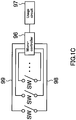
- the pair of fixed conductive portions 102 includes a first fixed conductive portion cA and a second fixed conductive portion cB that make up a pair of electrodes.
- the fixed conductive portions cA and cB both do not have a comb teeth shape overall.
- the fixed conductive portions cA and cB respectively have strip members tA and tB that are shaped as long and thin strips, and the strip members tA and tB (referred to as "strip members t" hereinafter when not distinguishing between them, and the same following for the reference signs of other constituent elements as well) are aligned in parallel with each other.
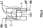
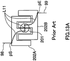
- strip members are employed in the switch of the comparative example shown in FIG. 4 as well, and that the external wiring patterns 98 and 99 are respectively connected to one end portion of each of the strip members t at the contact points pS and pE, which are power feed portions, as in the conventional example ( FIGS. 13A and 13B ).
- the length of the conductive path formed from the contact point pS to the contact point pE via the movable conductive portion 101 is L1.
- FIG. 5 is a schematic diagram of a specific example of the pair of fixed conductive portions 102 according to a first modified example.
- the strip members tA and tB are rectangular, and therefore an arrangement pitch P of the strip members tA and tB is the same at all positions in the extending direction, which is the direction orthogonal to the width direction (alignment direction) .
- the arrangement pitch P is defined as the distance between intermediate positions in the alignment direction. Note that letting D be the gap between the closest portions of the adjacent strip members tA and tB, the gap D is the same at all positions in the extending direction of the strip members tA and tB.
- the first main conductive pattern dA also extends under the strip members tA1 and tA2 on the substrate 93. Accordingly, practically, the first end portion tAlf and the second end portion tA1r have approximately the same potential, and the first end portion tA2f and the second end portion tA2r also have approximately the same potential.
- the second main conductive pattern dB also extends under the strip members tB1 and tB2. Accordingly, practically, the first end portion tB1f and the second end portion tB1r have approximately the same potential, and the first end portion tB2f and the second end portion tB2r also have approximately the same potential.
- the arrangement pitch of the central portion in the extending direction is smaller than that of the two end portions of the strip members t (on the first end portion tA2f and tB1f side, and on the second end portion tA2r and tB1r side) . Accordingly, even with a configuration in which the fixed conductive portions cA and cB each have two or more strip members t, the resistance value for the total length of the conductive path can be readily set smaller than in the configuration shown in FIG. 2 , and this is advantageous in improving the resistance characteristic.
- the strip members t need only be shaped as long and thin strips, are not required to have straight line portions, and may have an overall curved shape.
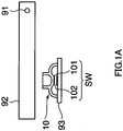
- the switch body 10 has one switch SW.
- two or more switches SW may be provided, and there are three switches SW in an exemplary configuration according to a second embodiment of the present invention.
- a movable conductive portion 101-1 and a pair of fixed conductive portions 102-1 constitute the switch SW1
- a movable conductive portion 101-2 and a pair of fixed conductive portions 102-2 constitute the switch SW2
- a movable conductive portion 101-3 and a pair of fixed conductive portions 102-3 constitute the switch SW3.
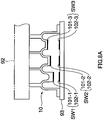
- FIG. 8B is a partial configuration diagram of a control circuit.
- the switches SW1, SW2, and SW3 are each connected to the external wiring pattern 98 via the first main conductive pattern dA. Also, the switches SW1, SW2, and SW3 are respectively connected to external wiring patterns 99-1, 99-2, and 99-3 via second main conductive patterns dB-1, dB-2, and dB-3.
- the second main conductive patterns dB-1, dB-2, and dB-3 are connected to the external wiring patterns 99-1, 99-2, and 99-3 through through-holes 81 (81-1, 81-2, 81-3) formed in the substrate 93. Two through-holes 81 are provided for each of the switches SW.
- Other configurations of the control circuit are the same as in the first embodiment.
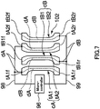
- the first fixed conductive portions cA (cA-1, cA-2, cA-3) and the second fixed conductive portions cB (cB-1, cB-2, cB-3) constitute the fixed conductive portions 102-1, 102-2, and 102-3.
- the first fixed conductive portion cA-1 has strip members tA1, tA2, and tA3
- the second fixed conductive portion cB-1 has strip members tB1 and tB2. In this way, an odd number of strip members t constitute the first fixed conductive portion cA, and an even number of strip members t constitute the second fixed conductive portion cB.
- holes 83 are formed in the resist 70 in correspondence with the through-holes 81 (81-1, 81-2, 81-3).
- the resist 70 is also provided with multiple conduction holes h for putting the main conductive patterns dA and dB and the fixed conductive portions cA and cB, which are laminated on each other, into conduction with each other.
- conduction holes h1 to h8 are formed.
- conduction holes h2 and h6 are formed at positions corresponding to the first end portion tB1f and the second end portion tB1r of the strip member tB1.
- the strip members tA1 and tA3 have a short length, and therefore one corresponding conduction hole h is provided for each of them, and the conduction efficiency is raised by causing the region spanning the two end portions in the extending direction of the strip members tA1 and tA3 to come into contact with the first main conductive pattern dA, but conduction holes h may be provided at positions corresponding to the two end portions.
- a configuration is possible in which a conduction hole h is added at a position corresponding to an intermediate position in the extending direction, thus causing these strip members to come into contact with the main conductive patterns dA and dB at an intermediate position in the extending direction in addition to the two end portions.
- the configurations of the fixed conductive portions cA-2, cA-3, cB-2, and cB-3 and the corresponding conduction holes h are the same as the configurations of the fixed conductive portions cA-1 and cB-1 and the corresponding conduction holes h.
- the main conductive patterns dA and dB are formed so as to be somewhat larger than or the same size as the fixed conductive portions cA and cB, and therefore the fixed conductive portions cA and cB are formed in ranges that do not extend beyond the main conductive patterns dA and dB.
- the first fixed conductive portion cA is laminated on the first main conductive pattern dA, and, regarding the arrangement range of the strip members t in the extending direction, the arrangement range of the first main conductive pattern dA contains the arrangement range of the strip members t that constitute the first fixed conductive portion cA.
- the second fixed conductive portion cB is laminated on the second main conductive pattern dB, and, regarding the arrangement range of the strip members t in the extending direction, the arrangement range of the second main conductive pattern dB contains the arrangement range of the strip members t that constitute the second fixed conductive portion cB.
- the main conductive patterns dA and dB have shapes that are approximately the same as the strip members constituting the fixed conductive portions cA and cB, and that the arrangement ranges thereof approximately match each other. Due to the resist 70 being arranged between the fixed conductive portions cA and cB and the main conductive patterns dA and dB, as long as the conduction holes h1 to h8 do not extend beyond the patterns of the fixed conductive portions cA and cB, even if the main conductive patterns dA and dB extend beyond the patterns of the fixed conductive portions cA and cB, shorting will not occur in this circuit.
- the main conductive patterns dA and dB are configured such that the portions thereof having the strip members t that constitute the fixed conductive portions cA and cB laminated thereon are continuous without interruptions in the extending direction of the strip members t. If the main conductive patterns dA and dB were partially non-continuous, portions of the surfaces of the fixed conductive portions cA and cB that come into contact with the movable conductive portion 101 would be low regions, and the band-shaped contact region would be non-continuous. As the number of such regions increases, the contact area decreases in size, and the total resistance increases.
- the main conductive patterns dA and dB are configured such that at least the portions thereof having the strip members t laminated thereon are continuous without interruption in the extending direction of the strip members t.
- the strip members tA2 in the center in the alignment direction in the respective first fixed conductive portions cA-1, cA-2, and cA-3 are connected by the same first main conductive pattern dA.
- the end portion of the strip member tA2 of one of the sets is physically connected to the end portion of the strip member tA2 of the other adjacent set.
- All of the strip members tA1 and tA3 that constitute the first fixed conductive portions cA-1, cA-2, and cA-3 are in electrical conduction with each other via the first main conductive pattern dA.
- strip members tA1, tA2 and tA3 that constitute the first fixed conductive portions cA-1, cA-2, and cA-3 are required to be in electrical conduction with each other.
- a configuration is possible in which at least one of strip members tA1, tA2 and tA3 of the fixed conductive portion is in electrical conduction with the one of other fixed conductive portion, and is connected to the microcomputer.
- a configuration is possible in which the gap between adjacent strip members tA2 is set to a gap of 0 by design, and the strip members tA2 may be non-continuous or continuous with each other.
- FIG. 11B a configuration is possible in which adjacent strip members tA2 are continuous with each other, and consequently the three strip members tA2 are continuous with each other.
- this configuration becomes difficult to realize with comb teeth-shaped fixed conductive portions.
- FIG. 12 is a schematic diagram of fixed conductive portions configured as described in a comparative example.
- the strip members tA that constitute the first fixed conductive portion cA-1 and the strip members tB that constitute the second fixed conductive portion cB-1 are arranged in an alternating manner.
- the strip members tA that constitute the first fixed conductive portion cA-2 and the strip members tB that constitute the second fixed conductive portion cB-2 are arranged in an alternating manner, but the arrangement sequence is different from that of the first switch, such that they alternate.
- the strip members tA must not be in electrical conduction with the strip members tB, and therefore in order to reliably ensure gaps between adjacent end portions of the strip members tA and strip members tB, leeway needs to be provided in design, with consideration given to manufacturing tolerance as well. In comparison to the present embodiment, this is therefore a disadvantage in terms of the close arrangement of switches.
- At least the two end portions of the strip members tA and tB are connected to the main conductive patterns dA and dB, thus making it possible to achieve the same effects as the first embodiment in terms of improving the resistance characteristic of the conductive path during switching.
- the arrangement pitch of the strip members t is smaller in the central portion in the extending direction than in the two end portions, and therefore it is possible to achieve the same effects as the configurations shown in FIGS. 5 and 7 in terms of making it easier to shorten the conductive path.
- the fixed conductive portions cA and cB are formed in ranges that do not extend beyond the main conductive patterns dA and dB, and therefore the surfaces that come into contact with the movable conductive portion 101 are more readily made smooth, thus making it possible to raise the circuit reliability.
- the adjacent end portions of strip members tA2 are physically connected to each other.
- multiple sets (three sets in the present embodiment) of conductive portions, each set including the first fixed conductive portion cA, the second fixed conductive portion cB, and the movable conductive portion 101, are provided in correspondence with one operator (switch body 10), the sets of conductive portions are arranged along the extending direction of the strip members t, and the respective adjacent end portions of the central strip member tA2 that constitutes the first fixed conductive portion cA of one set and the central strip member tA that constitutes the first fixed conductive portion cA of an adjacent set are physically connected to each other.
- multiple sets of conductive portions are arranged along the extending direction of the strip member refers to a state in which the arrangement direction of the sets and the extending direction of the strip member match each other to the extent that the end portions of strip members arranged in the center of adjacent sets can be physically connected, and the arrangement direction and the extending direction of the strip members are orthogonal to each other.
- the first fixed conductive portions cA (cA-1, cA-2, cA-3) each have three strip members tA (tAl, tA2, tA3)
- the second fixed conductive portions cB (cB-1, cB-2, cB-3) each have two strip members tB (tB1, tB2).
- the overall shape of the first and second fixed conductive portions is set to an elliptical shape.
- the key 92 and the substrate 93 of the electronic musical instrument according to the present embodiment have an elongated shape that is elongated in one direction, and their dimensional and positional precision are higher in the widthwise direction than in the lengthwise direction. For this reason, the probability distribution of positions of contact with the movable conductive portion has an elliptical shape.
- the conduction holes h1 and h5 may be made larger than the strip members tA1 and tA3 respectively.
- a configuration is possible in which that strip member tB or those strip members tB are in full-area contact with the second main conductive pattern dB.
- a configuration is possible in which in the strip members that constitute the first fixed conductive portion or the second fixed conductive portion and are located at the two ends in the alignment direction, the region spanning the two end portions in the extending direction comes into contact with the corresponding main conductive pattern. Accordingly, although the movable conductive portion 101 tends to unstably land on the strip members t at the two ends, the resistance value is lowered by causing the full area of the strip members t at the two ends to come into contact with the main conductive pattern, thus improving the resistance characteristic and making it possible to raise the operation detection precision.
Landscapes
- Engineering & Computer Science (AREA)
- Physics & Mathematics (AREA)
- Acoustics & Sound (AREA)
- Multimedia (AREA)
- Microelectronics & Electronic Packaging (AREA)
- Electrophonic Musical Instruments (AREA)
- Rotary Switch, Piano Key Switch, And Lever Switch (AREA)
- Contacts (AREA)
- Push-Button Switches (AREA)
Claims (8)
- Dispositif d'opérateur pour un instrument musical électronique, le dispositif d'opérateur comprenant :un substrat ;une première portion conductrice fixe (cA) et une seconde portion conductrice fixe (cB) qui sont agencées sur le substrat (93) et constituent une paire d'électrodes ;un premier motif conducteur principal (dA) et un second motif conducteur principal (dB) qui sont agencés sur le substrat (93), ont une conductivité plus élevée que les première et seconde portions conductrices fixes (cA, cB), et correspondent respectivement à la première portion conductrice fixe (cA) et à la seconde portion conductrice fixe (cB) ; etune portion conductrice mobile (101) qui est configurée pour se déplacer par une opération réalisée sur l'opérateur, et court-circuite électriquement la première portion conductrice fixe (cA) et la seconde portion conductrice fixe (cB) lorsqu'elle vient en contact avec les deux,dans lequel la première portion conductrice fixe (cA) et la seconde portion conductrice fixe (cB) sont chacune constituées d'au moins un organe de barrette (tA, tB), et l'organe de barrette (tA) constituant la première portion conductrice fixe (cA) et l'organe de barrette (tB) constituant la seconde portion conductrice fixe (cB) sont alignés en parallèle et de manière alternée, etau moins deux portions d'extrémité (tAf, tAr) de l'organe de barrette (tA) constituant la première portion conductrice fixe (cA) sont connectées électriquement au premier motif conducteur principal (dA), et au moins deux portions d'extrémité (tBf, tBr) de l'organe de barrette (tB) constituant la seconde portion conductrice fixe (cB) sont connectées électriquement au second motif conducteur principal (dB),caractérisé en ce quedans les organes de barrette (ta, tB) qui constituent la première portion conductrice fixe (cA) et la seconde portion conductrice fixe (cB), un pas d'agencement dans une direction d'alignement des organes de barrette (tA, tB) est plus petit dans une portion centrale dans une direction d'extension des organes de barrette (tA, tB) que dans les deux portions d'extrémité (tAf, tAr, tBf, tBr) des organes de barrette (tA, tB).
- Dispositif d'opérateur pour un instrument musical électronique selon la revendication 1,
dans lequel la première portion conductrice fixe (cA) est agencée sur un côté supérieur du premier motif conducteur principal (dA) dans une plage identique à une plage du premier motif conducteur principal (dA), ou est agencée sur le côté supérieur du premier motif conducteur principal (dA) dans une plage qui est contenue dans la plage du premier motif conducteur principal (dA) et est plus petite que la plage du premier motif conducteur principal (dA), et
la seconde portion conductrice fixe (cB) est agencée sur un côté supérieur du second motif conducteur principal (dB) dans une plage identique à une plage du second motif conducteur principal (dB), ou est agencée sur le côté supérieur du second motif conducteur principal (dB) dans une plage qui est contenue dans la plage du second motif conducteur principal (dB) et est plus petite que la plage du second motif conducteur principal (dB). - Dispositif d'opérateur pour un instrument musical électronique selon la revendication 1,
dans lequel la première portion conductrice fixe (cA) est stratifiée sur le premier motif conducteur principal (dA),
une plage d'agencement du premier motif conducteur principal (dA) dans la direction d'extension des organes de barrette (tA, tB) contient une plage d'agencement dans la direction d'extension de l'organe de barrette (tA) constituant la première portion conductrice fixe (cA),
une portion du premier motif conducteur principal (dA) ayant l'organe de barrette (tA) constituant la première portion conductrice fixe (cA) stratifiée dessus est continue sans interruption dans la direction d'extension de l'organe de barrette (tA),
la seconde portion conductrice fixe (cB) est stratifiée sur le second motif conducteur principal (dB),
une plage d'agencement du second motif conducteur principal (dB) dans la direction d'extension des organes de barrette (tA, tB) contient une plage d'agencement dans la direction d'extension de l'organe de barrette (tB) constituant la seconde portion conductrice fixe (cB), et
une portion du second motif conducteur principal (dB) ayant l'organe de barrette (tB) constituant la seconde portion conductrice fixe (cB) stratifiée dessus est continue sans interruption dans la direction d'extension de l'organe de barrette (tB). - Dispositif d'opérateur pour un instrument musical électronique selon l'une quelconque des revendications précédentes,
dans lequel une pluralité d'ensembles de portions conductrices, chaque ensemble comportant la première portion conductrice fixe (cA), la seconde portion conductrice fixe (cB), et la portion conductrice mobile (101), est prévue en correspondance avec un opérateur,
la pluralité d'ensembles est agencée le long de la direction d'extension des organes de barrette (tA, tB) constituant les premières portions conductrices fixes (cA) et les secondes portions conductrices fixes (cB) des ensembles, et
des portions d'extrémité adjacentes respectives de l'organe de barrette (tA) constituant la première portion conductrice fixe (cA) d'un ensemble et l'organe de barrette (tB) constituant la première portion conductrice fixe (cB) d'un ensemble adjacent sont connectées physiquement les unes aux autres. - Dispositif d'opérateur pour un instrument musical électronique selon la revendication 4, dans lequel le nombre d'ensembles est de trois ou plus.
- Dispositif d'opérateur pour un instrument musical électronique selon l'une quelconque des revendications précédentes, dans lequel un nombre impair d'organes de barrette (tAl, tA2, tA3) constitue la première portion conductrice fixe (cA), et un nombre pair d'organes de barrette (tB1, tB2) constitue la seconde portion conductrice fixe (cB).
- Dispositif d'opérateur pour un instrument musical électronique selon l'une quelconque des revendications précédentes, dans lequel la longueur de chaque organe de barrette (tA) constituant la première portion conductrice fixe (cA) et de chaque organe de barrette (tB) constituant la seconde portion conductrice fixe (cB) est plus courte plus l'organe de barrette (tA, tB) est loin d'un centre dans une direction d'alignement des organes de barrette (tA, tB).
- Dispositif d'opérateur pour un instrument musical électronique selon l'une quelconque des revendications précédentes, dans lequel dans des organes de barrette (tA, tB) qui constituent la première portion conductrice fixe (cA) ou la seconde portion conductrice fixe (cB) et qui sont situés au niveau de deux extrémités dans la direction d'alignement, une région couvrant deux portions d'extrémité dans la direction d'extension vient en contact avec le motif conducteur principal (dA, dB) correspondant.
Applications Claiming Priority (1)
| Application Number | Priority Date | Filing Date | Title |
|---|---|---|---|
| JP2015193263 | 2015-09-30 |
Publications (2)
| Publication Number | Publication Date |
|---|---|
| EP3151237A1 EP3151237A1 (fr) | 2017-04-05 |
| EP3151237B1 true EP3151237B1 (fr) | 2018-06-27 |
Family
ID=57047027
Family Applications (1)
| Application Number | Title | Priority Date | Filing Date |
|---|---|---|---|
| EP16191061.7A Active EP3151237B1 (fr) | 2015-09-30 | 2016-09-28 | Dispositif d'operation pour instrument de musique electronique |
Country Status (4)
| Country | Link |
|---|---|
| US (1) | US9767779B2 (fr) |
| EP (1) | EP3151237B1 (fr) |
| JP (1) | JP6724698B2 (fr) |
| CN (1) | CN107045952B (fr) |
Families Citing this family (1)
| Publication number | Priority date | Publication date | Assignee | Title |
|---|---|---|---|---|
| CN107045952B (zh) * | 2015-09-30 | 2019-07-19 | 雅马哈株式会社 | 用于电子乐器的操作器装置 |
Family Cites Families (9)
| Publication number | Priority date | Publication date | Assignee | Title |
|---|---|---|---|---|
| DE3041859A1 (de) * | 1980-11-06 | 1982-06-03 | Preh Elektro Feinmechanik | Tastatur |
| US4580478A (en) * | 1984-02-06 | 1986-04-08 | Bitronics, Inc. | Musical keyboard using planar coil arrays |
| CN2038653U (zh) * | 1988-07-28 | 1989-05-31 | 高建和 | 毯琴 |
| JPH07181970A (ja) | 1993-12-24 | 1995-07-21 | Roland Corp | 音響効果付加装置 |
| JP3000885B2 (ja) | 1994-12-28 | 2000-01-17 | ヤマハ株式会社 | スイッチ装置 |
| JP2904734B2 (ja) * | 1995-11-15 | 1999-06-14 | ユニデン株式会社 | スイッチ |
| JP2004022411A (ja) * | 2002-06-18 | 2004-01-22 | Mitsumi Electric Co Ltd | 接点機構 |
| JP2010282888A (ja) * | 2009-06-05 | 2010-12-16 | Panasonic Electric Works Co Ltd | 接点装置およびそれを用いたリレー装置 |
| CN107045952B (zh) * | 2015-09-30 | 2019-07-19 | 雅马哈株式会社 | 用于电子乐器的操作器装置 |
-
2016
- 2016-09-23 CN CN201610848920.8A patent/CN107045952B/zh active Active
- 2016-09-28 EP EP16191061.7A patent/EP3151237B1/fr active Active
- 2016-09-30 US US15/282,797 patent/US9767779B2/en active Active
- 2016-09-30 JP JP2016193160A patent/JP6724698B2/ja active Active
Non-Patent Citations (1)
| Title |
|---|
| None * |
Also Published As
| Publication number | Publication date |
|---|---|
| US9767779B2 (en) | 2017-09-19 |
| US20170092250A1 (en) | 2017-03-30 |
| JP6724698B2 (ja) | 2020-07-15 |
| JP2017068265A (ja) | 2017-04-06 |
| EP3151237A1 (fr) | 2017-04-05 |
| CN107045952B (zh) | 2019-07-19 |
| CN107045952A (zh) | 2017-08-15 |
Similar Documents
| Publication | Publication Date | Title |
|---|---|---|
| CN101820725B (zh) | 软性印制板 | |
| JP6249991B2 (ja) | 配線モジュール | |
| US7172446B1 (en) | Electrical connector | |
| US20100096165A1 (en) | Golden finger for flexible printed circuitboard | |
| JP5818516B2 (ja) | コネクタ接続部を有するフレキシブルプリント配線基板 | |
| JP4551776B2 (ja) | 両面fpc | |
| JP2014010966A (ja) | ハウジングレスコネクタ | |
| EP3151237B1 (fr) | Dispositif d'operation pour instrument de musique electronique | |
| KR20160048172A (ko) | 프린트 배선판 및 그 배선판을 접속하는 커넥터 | |
| US7731506B2 (en) | Pin layout of a golden finger for flexible printed circuitboard | |
| EP3483912B1 (fr) | Boucle électriquement conductrice d'un disjoncteur | |
| KR101516297B1 (ko) | 전자부품용 택트 스위치 | |
| JP5169308B2 (ja) | プリント基板、及び電子機器 | |
| CN101925254B (zh) | 柔性印刷基板以及使用柔性印刷基板的计算机 | |
| JP2005316037A (ja) | 表示装置 | |
| JP2000112625A (ja) | キーボードに搭載される発光素子の取付構造 | |
| JP4672925B2 (ja) | フレキシブル配線基板接続用コネクタ | |
| JP6942656B2 (ja) | プリント配線基板 | |
| US9378905B2 (en) | Inter-pole drive bar usable with switch apparatus having multiple poles | |
| US6169255B1 (en) | Flexible membrane circuit structure for keyswitch | |
| TW200514304A (en) | Structure for forming discharging path of a flexible printed circuit board | |
| CN110012594A (zh) | 一种柔性电路板及终端设备 | |
| CN220528277U (zh) | 柔性电路板和终端设备 | |
| CN103915277A (zh) | 调整构件和开关单元 | |
| US20050162037A1 (en) | Film like electrode member for electrostatic motor |
Legal Events
| Date | Code | Title | Description |
|---|---|---|---|
| PUAI | Public reference made under article 153(3) epc to a published international application that has entered the european phase |
Free format text: ORIGINAL CODE: 0009012 |
|
| AK | Designated contracting states |
Kind code of ref document: A1 Designated state(s): AL AT BE BG CH CY CZ DE DK EE ES FI FR GB GR HR HU IE IS IT LI LT LU LV MC MK MT NL NO PL PT RO RS SE SI SK SM TR |
|
| AX | Request for extension of the european patent |
Extension state: BA ME |
|
| 17P | Request for examination filed |
Effective date: 20170830 |
|
| RBV | Designated contracting states (corrected) |
Designated state(s): AL AT BE BG CH CY CZ DE DK EE ES FI FR GB GR HR HU IE IS IT LI LT LU LV MC MK MT NL NO PL PT RO RS SE SI SK SM TR |
|
| GRAP | Despatch of communication of intention to grant a patent |
Free format text: ORIGINAL CODE: EPIDOSNIGR1 |
|
| RIC1 | Information provided on ipc code assigned before grant |
Ipc: H01H 13/702 20060101ALI20171219BHEP Ipc: G10H 1/055 20060101AFI20171219BHEP |
|
| INTG | Intention to grant announced |
Effective date: 20180116 |
|
| RAP1 | Party data changed (applicant data changed or rights of an application transferred) |
Owner name: YAMAHA CORPORATION |
|
| GRAS | Grant fee paid |
Free format text: ORIGINAL CODE: EPIDOSNIGR3 |
|
| GRAA | (expected) grant |
Free format text: ORIGINAL CODE: 0009210 |
|
| AK | Designated contracting states |
Kind code of ref document: B1 Designated state(s): AL AT BE BG CH CY CZ DE DK EE ES FI FR GB GR HR HU IE IS IT LI LT LU LV MC MK MT NL NO PL PT RO RS SE SI SK SM TR |
|
| REG | Reference to a national code |
Ref country code: GB Ref legal event code: FG4D |
|
| REG | Reference to a national code |
Ref country code: AT Ref legal event code: REF Ref document number: 1012999 Country of ref document: AT Kind code of ref document: T Effective date: 20180715 |
|
| REG | Reference to a national code |
Ref country code: IE Ref legal event code: FG4D |
|
| REG | Reference to a national code |
Ref country code: DE Ref legal event code: R096 Ref document number: 602016003814 Country of ref document: DE |
|
| PG25 | Lapsed in a contracting state [announced via postgrant information from national office to epo] |
Ref country code: LT Free format text: LAPSE BECAUSE OF FAILURE TO SUBMIT A TRANSLATION OF THE DESCRIPTION OR TO PAY THE FEE WITHIN THE PRESCRIBED TIME-LIMIT Effective date: 20180627 Ref country code: BG Free format text: LAPSE BECAUSE OF FAILURE TO SUBMIT A TRANSLATION OF THE DESCRIPTION OR TO PAY THE FEE WITHIN THE PRESCRIBED TIME-LIMIT Effective date: 20180927 Ref country code: FI Free format text: LAPSE BECAUSE OF FAILURE TO SUBMIT A TRANSLATION OF THE DESCRIPTION OR TO PAY THE FEE WITHIN THE PRESCRIBED TIME-LIMIT Effective date: 20180627 Ref country code: NO Free format text: LAPSE BECAUSE OF FAILURE TO SUBMIT A TRANSLATION OF THE DESCRIPTION OR TO PAY THE FEE WITHIN THE PRESCRIBED TIME-LIMIT Effective date: 20180927 Ref country code: SE Free format text: LAPSE BECAUSE OF FAILURE TO SUBMIT A TRANSLATION OF THE DESCRIPTION OR TO PAY THE FEE WITHIN THE PRESCRIBED TIME-LIMIT Effective date: 20180627 |
|
| REG | Reference to a national code |
Ref country code: NL Ref legal event code: MP Effective date: 20180627 |
|
| REG | Reference to a national code |
Ref country code: LT Ref legal event code: MG4D |
|
| PG25 | Lapsed in a contracting state [announced via postgrant information from national office to epo] |
Ref country code: GR Free format text: LAPSE BECAUSE OF FAILURE TO SUBMIT A TRANSLATION OF THE DESCRIPTION OR TO PAY THE FEE WITHIN THE PRESCRIBED TIME-LIMIT Effective date: 20180928 Ref country code: HR Free format text: LAPSE BECAUSE OF FAILURE TO SUBMIT A TRANSLATION OF THE DESCRIPTION OR TO PAY THE FEE WITHIN THE PRESCRIBED TIME-LIMIT Effective date: 20180627 Ref country code: LV Free format text: LAPSE BECAUSE OF FAILURE TO SUBMIT A TRANSLATION OF THE DESCRIPTION OR TO PAY THE FEE WITHIN THE PRESCRIBED TIME-LIMIT Effective date: 20180627 Ref country code: RS Free format text: LAPSE BECAUSE OF FAILURE TO SUBMIT A TRANSLATION OF THE DESCRIPTION OR TO PAY THE FEE WITHIN THE PRESCRIBED TIME-LIMIT Effective date: 20180627 |
|
| REG | Reference to a national code |
Ref country code: AT Ref legal event code: MK05 Ref document number: 1012999 Country of ref document: AT Kind code of ref document: T Effective date: 20180627 |
|
| PG25 | Lapsed in a contracting state [announced via postgrant information from national office to epo] |
Ref country code: NL Free format text: LAPSE BECAUSE OF FAILURE TO SUBMIT A TRANSLATION OF THE DESCRIPTION OR TO PAY THE FEE WITHIN THE PRESCRIBED TIME-LIMIT Effective date: 20180627 |
|
| PG25 | Lapsed in a contracting state [announced via postgrant information from national office to epo] |
Ref country code: PL Free format text: LAPSE BECAUSE OF FAILURE TO SUBMIT A TRANSLATION OF THE DESCRIPTION OR TO PAY THE FEE WITHIN THE PRESCRIBED TIME-LIMIT Effective date: 20180627 Ref country code: RO Free format text: LAPSE BECAUSE OF FAILURE TO SUBMIT A TRANSLATION OF THE DESCRIPTION OR TO PAY THE FEE WITHIN THE PRESCRIBED TIME-LIMIT Effective date: 20180627 Ref country code: SK Free format text: LAPSE BECAUSE OF FAILURE TO SUBMIT A TRANSLATION OF THE DESCRIPTION OR TO PAY THE FEE WITHIN THE PRESCRIBED TIME-LIMIT Effective date: 20180627 Ref country code: CZ Free format text: LAPSE BECAUSE OF FAILURE TO SUBMIT A TRANSLATION OF THE DESCRIPTION OR TO PAY THE FEE WITHIN THE PRESCRIBED TIME-LIMIT Effective date: 20180627 Ref country code: EE Free format text: LAPSE BECAUSE OF FAILURE TO SUBMIT A TRANSLATION OF THE DESCRIPTION OR TO PAY THE FEE WITHIN THE PRESCRIBED TIME-LIMIT Effective date: 20180627 Ref country code: IS Free format text: LAPSE BECAUSE OF FAILURE TO SUBMIT A TRANSLATION OF THE DESCRIPTION OR TO PAY THE FEE WITHIN THE PRESCRIBED TIME-LIMIT Effective date: 20181027 Ref country code: AT Free format text: LAPSE BECAUSE OF FAILURE TO SUBMIT A TRANSLATION OF THE DESCRIPTION OR TO PAY THE FEE WITHIN THE PRESCRIBED TIME-LIMIT Effective date: 20180627 |
|
| PG25 | Lapsed in a contracting state [announced via postgrant information from national office to epo] |
Ref country code: ES Free format text: LAPSE BECAUSE OF FAILURE TO SUBMIT A TRANSLATION OF THE DESCRIPTION OR TO PAY THE FEE WITHIN THE PRESCRIBED TIME-LIMIT Effective date: 20180627 Ref country code: IT Free format text: LAPSE BECAUSE OF FAILURE TO SUBMIT A TRANSLATION OF THE DESCRIPTION OR TO PAY THE FEE WITHIN THE PRESCRIBED TIME-LIMIT Effective date: 20180627 Ref country code: SM Free format text: LAPSE BECAUSE OF FAILURE TO SUBMIT A TRANSLATION OF THE DESCRIPTION OR TO PAY THE FEE WITHIN THE PRESCRIBED TIME-LIMIT Effective date: 20180627 |
|
| REG | Reference to a national code |
Ref country code: DE Ref legal event code: R097 Ref document number: 602016003814 Country of ref document: DE |
|
| PG25 | Lapsed in a contracting state [announced via postgrant information from national office to epo] |
Ref country code: MC Free format text: LAPSE BECAUSE OF FAILURE TO SUBMIT A TRANSLATION OF THE DESCRIPTION OR TO PAY THE FEE WITHIN THE PRESCRIBED TIME-LIMIT Effective date: 20180627 |
|
| PLBE | No opposition filed within time limit |
Free format text: ORIGINAL CODE: 0009261 |
|
| STAA | Information on the status of an ep patent application or granted ep patent |
Free format text: STATUS: NO OPPOSITION FILED WITHIN TIME LIMIT |
|
| PG25 | Lapsed in a contracting state [announced via postgrant information from national office to epo] |
Ref country code: DK Free format text: LAPSE BECAUSE OF FAILURE TO SUBMIT A TRANSLATION OF THE DESCRIPTION OR TO PAY THE FEE WITHIN THE PRESCRIBED TIME-LIMIT Effective date: 20180627 |
|
| 26N | No opposition filed |
Effective date: 20190328 |
|
| REG | Reference to a national code |
Ref country code: BE Ref legal event code: MM Effective date: 20180930 |
|
| REG | Reference to a national code |
Ref country code: IE Ref legal event code: MM4A |
|
| PG25 | Lapsed in a contracting state [announced via postgrant information from national office to epo] |
Ref country code: LU Free format text: LAPSE BECAUSE OF NON-PAYMENT OF DUE FEES Effective date: 20180928 |
|
| PG25 | Lapsed in a contracting state [announced via postgrant information from national office to epo] |
Ref country code: IE Free format text: LAPSE BECAUSE OF NON-PAYMENT OF DUE FEES Effective date: 20180928 |
|
| PG25 | Lapsed in a contracting state [announced via postgrant information from national office to epo] |
Ref country code: SI Free format text: LAPSE BECAUSE OF FAILURE TO SUBMIT A TRANSLATION OF THE DESCRIPTION OR TO PAY THE FEE WITHIN THE PRESCRIBED TIME-LIMIT Effective date: 20180627 Ref country code: BE Free format text: LAPSE BECAUSE OF NON-PAYMENT OF DUE FEES Effective date: 20180930 Ref country code: FR Free format text: LAPSE BECAUSE OF NON-PAYMENT OF DUE FEES Effective date: 20180930 |
|
| PG25 | Lapsed in a contracting state [announced via postgrant information from national office to epo] |
Ref country code: AL Free format text: LAPSE BECAUSE OF FAILURE TO SUBMIT A TRANSLATION OF THE DESCRIPTION OR TO PAY THE FEE WITHIN THE PRESCRIBED TIME-LIMIT Effective date: 20180627 |
|
| PG25 | Lapsed in a contracting state [announced via postgrant information from national office to epo] |
Ref country code: MT Free format text: LAPSE BECAUSE OF NON-PAYMENT OF DUE FEES Effective date: 20180928 |
|
| PG25 | Lapsed in a contracting state [announced via postgrant information from national office to epo] |
Ref country code: TR Free format text: LAPSE BECAUSE OF FAILURE TO SUBMIT A TRANSLATION OF THE DESCRIPTION OR TO PAY THE FEE WITHIN THE PRESCRIBED TIME-LIMIT Effective date: 20180627 |
|
| PG25 | Lapsed in a contracting state [announced via postgrant information from national office to epo] |
Ref country code: PT Free format text: LAPSE BECAUSE OF FAILURE TO SUBMIT A TRANSLATION OF THE DESCRIPTION OR TO PAY THE FEE WITHIN THE PRESCRIBED TIME-LIMIT Effective date: 20180627 |
|
| REG | Reference to a national code |
Ref country code: CH Ref legal event code: PL |
|
| PG25 | Lapsed in a contracting state [announced via postgrant information from national office to epo] |
Ref country code: HU Free format text: LAPSE BECAUSE OF FAILURE TO SUBMIT A TRANSLATION OF THE DESCRIPTION OR TO PAY THE FEE WITHIN THE PRESCRIBED TIME-LIMIT; INVALID AB INITIO Effective date: 20160928 Ref country code: MK Free format text: LAPSE BECAUSE OF NON-PAYMENT OF DUE FEES Effective date: 20180627 Ref country code: CY Free format text: LAPSE BECAUSE OF FAILURE TO SUBMIT A TRANSLATION OF THE DESCRIPTION OR TO PAY THE FEE WITHIN THE PRESCRIBED TIME-LIMIT Effective date: 20180627 |
|
| PG25 | Lapsed in a contracting state [announced via postgrant information from national office to epo] |
Ref country code: LI Free format text: LAPSE BECAUSE OF NON-PAYMENT OF DUE FEES Effective date: 20190930 Ref country code: CH Free format text: LAPSE BECAUSE OF NON-PAYMENT OF DUE FEES Effective date: 20190930 |
|
| GBPC | Gb: european patent ceased through non-payment of renewal fee |
Effective date: 20200928 |
|
| PG25 | Lapsed in a contracting state [announced via postgrant information from national office to epo] |
Ref country code: GB Free format text: LAPSE BECAUSE OF NON-PAYMENT OF DUE FEES Effective date: 20200928 |
|
| PGFP | Annual fee paid to national office [announced via postgrant information from national office to epo] |
Ref country code: DE Payment date: 20250919 Year of fee payment: 10 |