EP3147441A1 - Elektromechanische stütze mit elektromechanischer bremse und verfahren zum erlauben und verhindern einer bewegung eines verschlusselementes eines fahrzeugs - Google Patents
Elektromechanische stütze mit elektromechanischer bremse und verfahren zum erlauben und verhindern einer bewegung eines verschlusselementes eines fahrzeugs Download PDFInfo
- Publication number
- EP3147441A1 EP3147441A1 EP16174128.5A EP16174128A EP3147441A1 EP 3147441 A1 EP3147441 A1 EP 3147441A1 EP 16174128 A EP16174128 A EP 16174128A EP 3147441 A1 EP3147441 A1 EP 3147441A1
- Authority
- EP
- European Patent Office
- Prior art keywords
- electromechanical
- brake assembly
- friction plate
- lead screw
- unit
- Prior art date
- Legal status (The legal status is an assumption and is not a legal conclusion. Google has not performed a legal analysis and makes no representation as to the accuracy of the status listed.)
- Withdrawn
Links
- 238000000034 method Methods 0.000 title claims abstract description 19
- 230000008878 coupling Effects 0.000 description 9
- 238000010168 coupling process Methods 0.000 description 9
- 238000005859 coupling reaction Methods 0.000 description 9
- 230000007246 mechanism Effects 0.000 description 9
- 125000006850 spacer group Chemical group 0.000 description 6
- 230000009467 reduction Effects 0.000 description 4
- 238000013461 design Methods 0.000 description 3
- 238000004519 manufacturing process Methods 0.000 description 2
- 239000000463 material Substances 0.000 description 2
- 230000004044 response Effects 0.000 description 2
- 238000010521 absorption reaction Methods 0.000 description 1
- 239000000853 adhesive Substances 0.000 description 1
- 230000001070 adhesive effect Effects 0.000 description 1
- 230000008901 benefit Effects 0.000 description 1
- 230000005540 biological transmission Effects 0.000 description 1
- 238000004891 communication Methods 0.000 description 1
- 230000006835 compression Effects 0.000 description 1
- 238000007906 compression Methods 0.000 description 1
- 210000005069 ears Anatomy 0.000 description 1
- 230000008030 elimination Effects 0.000 description 1
- 238000003379 elimination reaction Methods 0.000 description 1
- 239000002783 friction material Substances 0.000 description 1
- 238000002955 isolation Methods 0.000 description 1
- 230000013011 mating Effects 0.000 description 1
- 238000012986 modification Methods 0.000 description 1
- 230000004048 modification Effects 0.000 description 1
- 230000036316 preload Effects 0.000 description 1
- 238000012552 review Methods 0.000 description 1
- 230000035939 shock Effects 0.000 description 1
Images


Classifications
-
- E—FIXED CONSTRUCTIONS
- E05—LOCKS; KEYS; WINDOW OR DOOR FITTINGS; SAFES
- E05F—DEVICES FOR MOVING WINGS INTO OPEN OR CLOSED POSITION; CHECKS FOR WINGS; WING FITTINGS NOT OTHERWISE PROVIDED FOR, CONCERNED WITH THE FUNCTIONING OF THE WING
- E05F15/00—Power-operated mechanisms for wings
- E05F15/60—Power-operated mechanisms for wings using electrical actuators
- E05F15/603—Power-operated mechanisms for wings using electrical actuators using rotary electromotors
- E05F15/611—Power-operated mechanisms for wings using electrical actuators using rotary electromotors for swinging wings
- E05F15/616—Power-operated mechanisms for wings using electrical actuators using rotary electromotors for swinging wings operated by push-pull mechanisms
- E05F15/622—Power-operated mechanisms for wings using electrical actuators using rotary electromotors for swinging wings operated by push-pull mechanisms using screw-and-nut mechanisms
-
- B—PERFORMING OPERATIONS; TRANSPORTING
- B60—VEHICLES IN GENERAL
- B60J—WINDOWS, WINDSCREENS, NON-FIXED ROOFS, DOORS, OR SIMILAR DEVICES FOR VEHICLES; REMOVABLE EXTERNAL PROTECTIVE COVERINGS SPECIALLY ADAPTED FOR VEHICLES
- B60J5/00—Doors
- B60J5/10—Doors arranged at the vehicle rear
-
- E—FIXED CONSTRUCTIONS
- E05—LOCKS; KEYS; WINDOW OR DOOR FITTINGS; SAFES
- E05F—DEVICES FOR MOVING WINGS INTO OPEN OR CLOSED POSITION; CHECKS FOR WINGS; WING FITTINGS NOT OTHERWISE PROVIDED FOR, CONCERNED WITH THE FUNCTIONING OF THE WING
- E05F1/00—Closers or openers for wings, not otherwise provided for in this subclass
- E05F1/08—Closers or openers for wings, not otherwise provided for in this subclass spring-actuated, e.g. for horizontally sliding wings
- E05F1/10—Closers or openers for wings, not otherwise provided for in this subclass spring-actuated, e.g. for horizontally sliding wings for swinging wings, e.g. counterbalance
- E05F1/1041—Closers or openers for wings, not otherwise provided for in this subclass spring-actuated, e.g. for horizontally sliding wings for swinging wings, e.g. counterbalance with a coil spring perpendicular to the pivot axis
-
- E—FIXED CONSTRUCTIONS
- E05—LOCKS; KEYS; WINDOW OR DOOR FITTINGS; SAFES
- E05F—DEVICES FOR MOVING WINGS INTO OPEN OR CLOSED POSITION; CHECKS FOR WINGS; WING FITTINGS NOT OTHERWISE PROVIDED FOR, CONCERNED WITH THE FUNCTIONING OF THE WING
- E05F3/00—Closers or openers with braking devices, e.g. checks; Construction of pneumatic or liquid braking devices
- E05F3/16—Closers or openers with braking devices, e.g. checks; Construction of pneumatic or liquid braking devices with friction brakes
-
- F—MECHANICAL ENGINEERING; LIGHTING; HEATING; WEAPONS; BLASTING
- F16—ENGINEERING ELEMENTS AND UNITS; GENERAL MEASURES FOR PRODUCING AND MAINTAINING EFFECTIVE FUNCTIONING OF MACHINES OR INSTALLATIONS; THERMAL INSULATION IN GENERAL
- F16H—GEARING
- F16H25/00—Gearings comprising primarily only cams, cam-followers and screw-and-nut mechanisms
- F16H25/18—Gearings comprising primarily only cams, cam-followers and screw-and-nut mechanisms for conveying or interconverting oscillating or reciprocating motions
- F16H25/20—Screw mechanisms
- F16H25/24—Elements essential to such mechanisms, e.g. screws, nuts
- F16H25/2454—Brakes; Rotational locks
-
- E—FIXED CONSTRUCTIONS
- E05—LOCKS; KEYS; WINDOW OR DOOR FITTINGS; SAFES
- E05Y—INDEXING SCHEME ASSOCIATED WITH SUBCLASSES E05D AND E05F, RELATING TO CONSTRUCTION ELEMENTS, ELECTRIC CONTROL, POWER SUPPLY, POWER SIGNAL OR TRANSMISSION, USER INTERFACES, MOUNTING OR COUPLING, DETAILS, ACCESSORIES, AUXILIARY OPERATIONS NOT OTHERWISE PROVIDED FOR, APPLICATION THEREOF
- E05Y2201/00—Constructional elements; Accessories therefor
- E05Y2201/20—Brakes; Disengaging means; Holders; Stops; Valves; Accessories therefor
- E05Y2201/21—Brakes
-
- E—FIXED CONSTRUCTIONS
- E05—LOCKS; KEYS; WINDOW OR DOOR FITTINGS; SAFES
- E05Y—INDEXING SCHEME ASSOCIATED WITH SUBCLASSES E05D AND E05F, RELATING TO CONSTRUCTION ELEMENTS, ELECTRIC CONTROL, POWER SUPPLY, POWER SIGNAL OR TRANSMISSION, USER INTERFACES, MOUNTING OR COUPLING, DETAILS, ACCESSORIES, AUXILIARY OPERATIONS NOT OTHERWISE PROVIDED FOR, APPLICATION THEREOF
- E05Y2201/00—Constructional elements; Accessories therefor
- E05Y2201/20—Brakes; Disengaging means; Holders; Stops; Valves; Accessories therefor
- E05Y2201/214—Disengaging means
- E05Y2201/216—Clutches
-
- E—FIXED CONSTRUCTIONS
- E05—LOCKS; KEYS; WINDOW OR DOOR FITTINGS; SAFES
- E05Y—INDEXING SCHEME ASSOCIATED WITH SUBCLASSES E05D AND E05F, RELATING TO CONSTRUCTION ELEMENTS, ELECTRIC CONTROL, POWER SUPPLY, POWER SIGNAL OR TRANSMISSION, USER INTERFACES, MOUNTING OR COUPLING, DETAILS, ACCESSORIES, AUXILIARY OPERATIONS NOT OTHERWISE PROVIDED FOR, APPLICATION THEREOF
- E05Y2201/00—Constructional elements; Accessories therefor
- E05Y2201/20—Brakes; Disengaging means; Holders; Stops; Valves; Accessories therefor
- E05Y2201/23—Actuation thereof
- E05Y2201/246—Actuation thereof by auxiliary motors, magnets, springs or weights
-
- E—FIXED CONSTRUCTIONS
- E05—LOCKS; KEYS; WINDOW OR DOOR FITTINGS; SAFES
- E05Y—INDEXING SCHEME ASSOCIATED WITH SUBCLASSES E05D AND E05F, RELATING TO CONSTRUCTION ELEMENTS, ELECTRIC CONTROL, POWER SUPPLY, POWER SIGNAL OR TRANSMISSION, USER INTERFACES, MOUNTING OR COUPLING, DETAILS, ACCESSORIES, AUXILIARY OPERATIONS NOT OTHERWISE PROVIDED FOR, APPLICATION THEREOF
- E05Y2201/00—Constructional elements; Accessories therefor
- E05Y2201/40—Motors; Magnets; Springs; Weights; Accessories therefor
- E05Y2201/43—Motors
- E05Y2201/434—Electromotors; Details thereof
-
- E—FIXED CONSTRUCTIONS
- E05—LOCKS; KEYS; WINDOW OR DOOR FITTINGS; SAFES
- E05Y—INDEXING SCHEME ASSOCIATED WITH SUBCLASSES E05D AND E05F, RELATING TO CONSTRUCTION ELEMENTS, ELECTRIC CONTROL, POWER SUPPLY, POWER SIGNAL OR TRANSMISSION, USER INTERFACES, MOUNTING OR COUPLING, DETAILS, ACCESSORIES, AUXILIARY OPERATIONS NOT OTHERWISE PROVIDED FOR, APPLICATION THEREOF
- E05Y2201/00—Constructional elements; Accessories therefor
- E05Y2201/40—Motors; Magnets; Springs; Weights; Accessories therefor
- E05Y2201/46—Magnets
- E05Y2201/462—Electromagnets
-
- E—FIXED CONSTRUCTIONS
- E05—LOCKS; KEYS; WINDOW OR DOOR FITTINGS; SAFES
- E05Y—INDEXING SCHEME ASSOCIATED WITH SUBCLASSES E05D AND E05F, RELATING TO CONSTRUCTION ELEMENTS, ELECTRIC CONTROL, POWER SUPPLY, POWER SIGNAL OR TRANSMISSION, USER INTERFACES, MOUNTING OR COUPLING, DETAILS, ACCESSORIES, AUXILIARY OPERATIONS NOT OTHERWISE PROVIDED FOR, APPLICATION THEREOF
- E05Y2201/00—Constructional elements; Accessories therefor
- E05Y2201/60—Suspension or transmission members; Accessories therefor
- E05Y2201/622—Suspension or transmission members elements
- E05Y2201/696—Screw mechanisms
-
- E—FIXED CONSTRUCTIONS
- E05—LOCKS; KEYS; WINDOW OR DOOR FITTINGS; SAFES
- E05Y—INDEXING SCHEME ASSOCIATED WITH SUBCLASSES E05D AND E05F, RELATING TO CONSTRUCTION ELEMENTS, ELECTRIC CONTROL, POWER SUPPLY, POWER SIGNAL OR TRANSMISSION, USER INTERFACES, MOUNTING OR COUPLING, DETAILS, ACCESSORIES, AUXILIARY OPERATIONS NOT OTHERWISE PROVIDED FOR, APPLICATION THEREOF
- E05Y2900/00—Application of doors, windows, wings or fittings thereof
- E05Y2900/50—Application of doors, windows, wings or fittings thereof for vehicles
- E05Y2900/53—Type of wing
- E05Y2900/531—Doors
- E05Y2900/532—Back doors or end doors
-
- E—FIXED CONSTRUCTIONS
- E05—LOCKS; KEYS; WINDOW OR DOOR FITTINGS; SAFES
- E05Y—INDEXING SCHEME ASSOCIATED WITH SUBCLASSES E05D AND E05F, RELATING TO CONSTRUCTION ELEMENTS, ELECTRIC CONTROL, POWER SUPPLY, POWER SIGNAL OR TRANSMISSION, USER INTERFACES, MOUNTING OR COUPLING, DETAILS, ACCESSORIES, AUXILIARY OPERATIONS NOT OTHERWISE PROVIDED FOR, APPLICATION THEREOF
- E05Y2900/00—Application of doors, windows, wings or fittings thereof
- E05Y2900/50—Application of doors, windows, wings or fittings thereof for vehicles
- E05Y2900/53—Type of wing
- E05Y2900/546—Tailboards, tailgates or sideboards opening upwards
-
- F—MECHANICAL ENGINEERING; LIGHTING; HEATING; WEAPONS; BLASTING
- F16—ENGINEERING ELEMENTS AND UNITS; GENERAL MEASURES FOR PRODUCING AND MAINTAINING EFFECTIVE FUNCTIONING OF MACHINES OR INSTALLATIONS; THERMAL INSULATION IN GENERAL
- F16H—GEARING
- F16H25/00—Gearings comprising primarily only cams, cam-followers and screw-and-nut mechanisms
- F16H25/18—Gearings comprising primarily only cams, cam-followers and screw-and-nut mechanisms for conveying or interconverting oscillating or reciprocating motions
- F16H25/20—Screw mechanisms
- F16H2025/2062—Arrangements for driving the actuator
- F16H2025/2075—Coaxial drive motors
-
- F—MECHANICAL ENGINEERING; LIGHTING; HEATING; WEAPONS; BLASTING
- F16—ENGINEERING ELEMENTS AND UNITS; GENERAL MEASURES FOR PRODUCING AND MAINTAINING EFFECTIVE FUNCTIONING OF MACHINES OR INSTALLATIONS; THERMAL INSULATION IN GENERAL
- F16H—GEARING
- F16H25/00—Gearings comprising primarily only cams, cam-followers and screw-and-nut mechanisms
- F16H25/18—Gearings comprising primarily only cams, cam-followers and screw-and-nut mechanisms for conveying or interconverting oscillating or reciprocating motions
- F16H25/20—Screw mechanisms
- F16H2025/2062—Arrangements for driving the actuator
- F16H2025/2087—Arrangements for driving the actuator using planetary gears
-
- F—MECHANICAL ENGINEERING; LIGHTING; HEATING; WEAPONS; BLASTING
- F16—ENGINEERING ELEMENTS AND UNITS; GENERAL MEASURES FOR PRODUCING AND MAINTAINING EFFECTIVE FUNCTIONING OF MACHINES OR INSTALLATIONS; THERMAL INSULATION IN GENERAL
- F16H—GEARING
- F16H25/00—Gearings comprising primarily only cams, cam-followers and screw-and-nut mechanisms
- F16H25/18—Gearings comprising primarily only cams, cam-followers and screw-and-nut mechanisms for conveying or interconverting oscillating or reciprocating motions
- F16H25/20—Screw mechanisms
- F16H25/24—Elements essential to such mechanisms, e.g. screws, nuts
- F16H25/2454—Brakes; Rotational locks
- F16H2025/2463—Brakes; Rotational locks using a wrap spring brake, i.e. a helical wind up spring for braking or locking
Definitions
- the present disclosure relates generally to an electromechanical support for opening and closing a vehicle closure element, and more particularly to an electromechanical support having a motor operatively coupled to drive a lead screw and an electromechanical brake facilitating the lead screw to hold in a releasably fixed position.
- Vehicle closure elements such as lift doors and side doors
- Vehicle closure elements provide convenient access to the interior of a vehicle, such as the loading areas of hatchback vehicles, vans and other utility vehicles.
- a lift door or side door is manually operated, requiring manual effort to move the lift door or door between the open and closed positions. Depending on the size and weight of the lift door or door, this effort may be difficult for some users.
- manually opening or closing a lift door or side door can be inconvenient, especially if the user has his hands full.
- Automated powered closure systems used for opening and closing vehicle lift doors are well known in the art and typically include a powered actuator that is operable to apply a force directly to the lift door so as to allow it to open and close ,
- a powered actuator that is operable to apply a force directly to the lift door so as to allow it to open and close
- US Patent 6,516,567 a powered actuator that works together with a gas prop.
- the powered actuator includes a motor mounted within the vehicle body connected via a coupling to a flexible rotary cable.
- the flexible rotary cable drives an extendable support that is pivotally mounted to both the vehicle body and the lift door.
- a control unit operable to engage and disengage the motor may be connected to a button on a remote control or to a button in the passenger compartment, thereby providing additional convenience.
- the powered actuator includes multiple parts, each of which must be assembled and separately mounted to the vehicle, which adds to the cost.
- the vehicle body must be specially designed to provide a space for receiving the engine. Due to the limited space available, the engine is small and requires the support of the gas prop. Further, since the driven actuator is adapted to work together with a gas post, the gas post may still vary in effectiveness due to temperature. Thus, the envisaged engine must be balanced to provide the correct amount of propulsion with varying degrees of mechanical support from the gas strut.
- the US publication number US 2004/0084265 provides various examples of powered actuators that work in conjunction with gas pedestals and various alternative examples of electromechanical driven actuators.
- These electromechanical powered actuators comprise an electric motor and a reduction gear set, which is coupled via a flexible rotary cable with a second gear set, which in turn is connected via a slip clutch with a rotatable piston rod.
- Rotation of the piston rod causes a spindle drive mechanism to move an extendable support that is configured to be pivotally mounted to a vehicle body and the lift door.
- the slip clutch functions to allow the piston rod to rotate relative to the gear set when torque exceeding its preload is applied to the lift door to accommodate manual actuation of the lift door without damaging the electromechanically driven actuator.
- the slip clutch removably couples the gear set to the piston rod, thereby providing the powered opening and closing of the lift door during normal operation.
- the slip clutch temporarily releases the drive connection between the piston rod and the gear set to a mechanical Prevent damage to the system.
- a helical compression spring is installed in the driven actuator to provide a counterbalancing counterforce to the weight of the lift gate, which in turn increases the size and weight of the assembly.
- the US publication number US 2012/0000304 describes various embodiments of powered operating mechanisms for moving trunk lids and lift doors between the open and closed positions.
- the driven operating mechanisms have a staggered arrangement with an electric motor driven worm gear, to rotate an externally threaded collar screw to move an extendable support.
- a slip clutch is disposed between an output gear of the worm gear and the rotatable collar screw.
- a coupling unit is provided between the motor output shaft and the worm of the worm gear.
- the coupling unit comprises a first coupling element fixed for rotation with the worm shaft, a second coupling element fixed for rotation with the motor output shaft, and an elastic band interposed between fingers extending from the first and second extend the second coupling element.
- the flexible coupling provides axial and circumferential isolation between the first and second coupling elements and functions to absorb momentary or rotating shock loads between the motor shaft and the worm shaft.
- the electromechanical brake of the support includes a first friction plate operably coupled to a shaft of the motor for co-rotation therewith, a second friction plate, a spring element, and an electrical coil.
- the brake has a normal "on position” in which the coil spring biases the second friction plate in contact with the first friction plate, so that the second friction plate prevents the first friction plate and the motor shaft from rotating, which in turn causes movement of the transmission case and Leadscrew prevented. Accordingly, by holding the lead screw in a fixed position, the electromechanical brake, while in the "on" position, prevents movement of the associated vehicle closure member.
- the electric coil is energized to generate a magnetic field.
- the magnetic force pulls the second friction plate out of contact with the first friction plate.
- the motor is also powered so that the first friction plate and the motor shaft rotate to bring the gearbox and thus the lead screw into the new position.
- aspects of the present disclosure include a method of manufacturing the electromechanical post and a method of opening, closing, and holding the vehicle closure element in a fixed position using the electromechanical post.
- an electromechanical support for moving a closure member of a vehicle between an open position and a closed position includes a powered drive unit operatively connected to one of the closure member and the motor vehicle body.
- the powered drive unit includes a housing having an inner surface defining a cavity extending along a central axis between opposing first and second ends.
- a motor is fixed in the cavity, a lead screw is disposed in the cavity, a planetary gear set connects a motor shaft of the motor to the lead screw, and an electromechanical brake assembly is operatively connected to the motor shaft.
- the electromagnetic support further includes a telescopic unit operatively connected to the other, the closure member and the motor vehicle body.
- the telescopic unit comprises an extendable tube, at least is partially received in the cavity of the housing, and further comprises a drive nut for converting a rotational movement of the lead screw in a linear movement of the telescopic unit to move the telescopic unit between a retracted position relative to the housing and an extended position relative to the housing.
- the electromagnetic brake assembly is selectively movable between an engaged state and a non-engaged state.
- the motor shaft and the lead screw are prevented from rotating when the electromagnetic brake assembly is in the engaged state to prevent relative axial movement between the drive unit and the telescopic unit.
- the motor shaft and the lead screw may rotate when the electromechanical brake assembly is in the disengaged state to permit relative axial movement between the powered drive unit and the telescoping unit.
- the electromechanical brake assembly has a coil assembly that is operatively connected to a source of electrical current.
- the electromechanical brake assembly remains in the engaged state when the coil assembly is turned off due to the absence of electrical current and is selectively moved to the disengaged condition when the coil assembly is selectively powered by electrical current.
- the electromechanical brake assembly includes a first friction plate and a second friction plate.
- the first and second friction plates are biased into frictional engagement with each other when the coil assembly is turned off, and the first and second friction plates are moved out of frictional engagement with each other by a magnetic force output from the coil assembly when the coil assembly is selectively energized.
- the electromechanical brake assembly includes a spring member that frictionally urges the first and second friction plates together when the coil assembly is turned off, thereby overcoming the force of the spring to allow the first and second friction plates to overcome Move friction plates from the frictional engagement with each other when the coil assembly is fed.
- the extendable tube of the telescoping unit is a single walled tube and does not include a compensating spring element.
- a method for allowing and preventing movement of a closure member of a vehicle between an open position and a closed position with an electromechanical support.
- the electromechanical support has a powered drive unit operatively connected to one of the closure member and the motor vehicle body, the driven drive unit including a motor, a lead screw, a planetary gear set operatively connecting a motor shaft of the motor to the lead screw, an electromechanical brake assembly , which is operatively connected to the motor shaft, and a telescopic unit, which is operatively connected to the other, the closure element and the motor vehicle body, wherein the telescopic unit comprises an extendable tube and a drive nut for converting a rotational movement of the lead screw into a linear movement of the telescope unit to move the telescope unit between a retracted position and an extended position.
- the method includes selectively instructing the electromechanical brake assembly to move to an engaged state to prevent the motor shaft and lead screw from rotating and prevent relative axial movement between the powered drive unit and the telescope unit, and selectively instructing the electromechanical brake assembly to move a disengaged state to allow the motor shaft and lead screw to rotate and allow relative axial movement between the driven drive unit and the telescoping unit.
- the method further comprises shutting off a coil assembly of the electro-mechanical brake assembly to hold the electro-mechanical brake assembly in the engaged state, and energizing the solenoid assembly of the electro-mechanical brake assembly to place the electro-mechanical brake assembly in the non-engaged state. To move engagement state.
- the method further comprises biasing first and second friction plates of the electro-mechanical brake assembly into frictional engagement with each other when the spool assembly is turned off, and moving the first and second friction plates out of frictional engagement with each other by a magnetic force. which is output from the coil assembly when the coil assembly is powered.
- the method further comprises biasing the first and second friction plates of the electro-mechanical brake assembly into frictional engagement with each other with a spring element when the coil assembly is turned off.
- the method further comprises moving the second friction plate axially away from the first friction plate under the influence of the magnetic force in selectively energizing the coil assembly via an instruction from an electronic control unit.
- the method may further comprise providing the extendable tube of the telescoping unit as a single tube without a compensating spring element.
- Vehicles in particular passenger vehicles are provided with movable closure plates for the creation of openings, passages and access within and through defined parts of the vehicle body.
- powered locking systems to automatically control the movement of all types of shutters including, without limitation, floating rear doors, side doors, trunk and hood covers, sliding and swing doors, sunroofs, and the like.
- the disclosure will be described herein in the context of a powered lift door or side door.
- inventive concepts of the present disclosure may be employed in myriad other systems and applications, and that the specific embodiments described and illustrated herein are exemplary, and not limitative.
- the present disclosure is directed to electromechanical props having a powered drive mechanism including a housing, an electric motor, a motor vehicle Reduction gear set, which is operated by the electric motor, a rotatable power screw, a coupling device, which is operatively disposed between the gear set and the power screw, an extendable member which is linearly movable relative to the housing comprises.
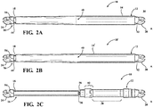
- the electromechanical support 10 includes a powered drive unit 12 housed in an outer housing or tube, hereinafter simply referred to as a housing 14, an extendable member, also referred to as a telescoping unit 16, received in a lower housing or tube is, hereinafter referred to simply as extendable tube 18.
- a first pivot bracket 20, such as a 10 mm ball pivot, as an example and without limitation, fixed to a first end 22 of the bracket 10 is pivotally mounted to a portion of the vehicle body adjacent an interior cargo area of the vehicle 11.
- a second pivot bracket 24, such as a 10 mm ball pivot, as an example and without limitation, attached to a second end 26 of the bracket 10 is pivotally mounted to a lift door 28 of the vehicle 11, by way of example and not limitation.
- the electromechanical support 10 provides improved actuation in a compact, reduced weight arrangement through a minimum number of components and with a reduced outer diameter or cross-sectional area.
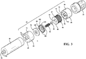
- the support 10 includes a motor gear assembly 30 that includes a motor 32, a gear box, also referred to as a planetary gear set 34, and a power screw, also referred to as Lead screw 36 is designated.
- the ability to provide the electromechanical support 10 in a compact, reduced weight configuration is provided, at least in part, by an integral electro-mechanical brake assembly, hereinafter simply referred to as a brake 38.
- the brake 38 When the brake 38 is in its normal closed position, also referred to as the "on” or “engaged” state, it provides additional holding force to relatively bias the driven driver 12 and the telescoping unit 16 in axially fixed or substantially fixed positions to hold each other. Conversely, when the brake 38 is selectively moved to an open position, also referred to as the “off position” or “disengaged state,” the telescoping unit 16 is able to move to a new axial position relative to the driven drive unit 12. so as to open or close the lift door 24 or side door of the vehicle 11, for example and without limitation.
- the electromechanical support 10 or brake 38 of the support 10 of the present disclosure may be used in lieu of or together with, respectively, the electromechanical supports disclosed in the Provisional U.S. Patent Application 62/083419 filed on November 24, 2014, the provisional U.S. Patent Application 62/109157 , which was submitted on January 29, 2015, the provisional U.S. Patent Application 62/204154 , which was submitted on August 12, 2015, the U.S. Patent Application 14/750 042 filed on 15 June 2015 and the U.S. Patent Application 14 / 938,156 filed on 11 November 2015, all of which are incorporated herein by reference in their entirety.
- This patent application makes it clear how different components of the electromechanical struts 10 of the present disclosure operate relative to each other and how the strut 10 of the present disclosure may be incorporated into a vehicle application.
- the illustrated electromechanical post 10 includes several features and their omission, which contributes to the improved operation, reduced weight, and compact design of the post 10.
- the exemplary support 10 obviates the need for a balance spring element such as a coil spring, typically within or at one Telescope unit of the supports is used, which were discussed in the background.
- the elimination of the balance spring provides the ability to design the electromagnetic support 10 with a reduced diameter and / or cross-sectional area which allows the weight of the support 10 to be reduced as a result of the minimized size of the support 10 and the omission of the balance spring material. and the outer shell is reduced, resulting in a compact design.
- the outer housing 14 has a tubular wall with an outer surface 40 extending along a longitudinal axis A between the opposed first and second ends 42, 44, and an inner surface 46 defining a cavity or chamber 48 for at least a partial receptacle of the engine-transmission arrangement 30 is dimensioned therein.
- the engine 32 and the planetary gear set 34 are stored within the chamber 48.
- the lead screw 36 is disposed within the telescopic unit 16 and coupled to an output rotary shaft 50 of the power driven unit 12.
- the planetary gear set 34 which is known per se in the art, provides a gear ratio reduction of about 20: 1, for example and without limitation.
- the gear set 34 may be as described in any of the above referenced documents incorporated herein by reference and may be used with any desired gear ratio reduction.
- the powered drive unit 12 has the feature of a clutch 52 that allows the power unit 12 to be quickly and easily connected to the telescoping unit 16.
- the tubular wall of the outer housing 14 includes a pair of cylindrical tubes connected to each other, although it should be noted that as shown in FIG. 2B
- a tubular wall of the housing 14' may be provided as a single tubular member, if desired, all the same or substantially the same is.
- the motor 32 and the gear set 34 are arranged along the axis A between the lead screw 36 and the electro-mechanical brake assembly 38 so that the brake assembly 38 is disposed between the motor 32 and the first end 42 of the housing 14, and the motor 32 is between Gear set 34 and the electromechanical brake assembly 38 is arranged.
- the electromechanical brake assembly 38 could be disposed on the opposite side of the motor 22 and the gear box 24, as one skilled in the art will appreciate upon review of the disclosure herein.
- the telescoping unit 16 includes the single-walled extendable tube 18 extending along the longitudinal axis A between the opposed first and second ends 54, 56 and having an inner surface 58 defining a cavity or chamber 60 adapted to receive the lead screw 36 is measured.
- One end 54 of the extendable tube 18 is rigidly connected to the second pivot mount 24, for example via mating helical threads for connecting the parts, for example and without limitation.
- the extendable tube 18 has a drive nut 62 fixedly mounted in its chamber 60 adjacent its second end 56, for example via interference fit and / or adhesive attachment therein or riveted connection, for example and without limitation.
- the drive nut 62 is threadedly coupled to the lead screw 36 to translate the rotational movement of the lead screw 36 into a linear movement of the telescoping unit 16 along the longitudinal center axis A of the support 10.
- an annular low friction wear sleeve 64 may be fixed adjacent the end 63 of the lead screw 36 with any suitable attachment mechanism.
- the wear sleeve 64 remains axially fixed with respect to the lead screw 36 and facilitates guidance of smooth axial movement of the extendable tube 18 as it moves axially along the external thread of the lead screw 36 in response to the axial movement of the drive nut 62.
- the electro-mechanical brake assembly 38 includes a brake housing 66 having a final mounting surface 68 and an annular outer wall 70 that, as shown, generally is cylindrical and defines an inner cavity 72 which is sized for the substantial absorption of various components of the brake assembly 38.
- the final mounting surface 68 is shown having a plurality of fastener receiving apertures 74 therethrough, the fastener means being threadedly engaged with threaded engagement means 76 in one end of the motor 32 (FIGS. Figures 4 A-4B ), for example and without limitation.
- the brake assembly 38 further includes a first friction plate 78, also referred to as a rotating brake disk, and a second friction plate 80, also referred to as a non-rotating or sliding brake disk, a spring member, such as, but not limited to, a coil spring 82 is a spacer 84, also referred to as a spacer, an electromagnetic coil assembly 86, such as, but not limited to, a coil assembly having a conductive electrical wire 87 wound helically around a bobbin 89 and in operative electrical connection with a source of electrical current is formed, and a coil housing 88th
- the bobbin case has an annular outer wall 90 and a central tubular post 92 extending along the axis A from an end wall 93 to a free end, with an annular cavity 94 extending between the wall 90 and the spigot 92 for receiving the spool assembly 86 extends therein.
- the bobbin 89 of the coil assembly 86 has a through aperture or aperture 95 sized to closely receive an outer surface of the pin 92 and is sized for close reception within the cavity 94 of the bobbin case 88. How best in the FIGS.
- the spacer 84 is arranged in a cavity or a pocket 96 which is bounded by the wall of the tubular pin 92, so that the spacer 84 is brought into abutment with the end wall 93.
- the spring element 82 is disposed in the pocket 96 against the spacer 84, the spring element 82 having a length sufficient to extend axially along the axis A outwardly from and over a free end 91 of the tubular pin 92, while FIG it is in an unstressed, axially decompressed state.
- the spacer 84 may be provided with the desired axial thickness to adjust the force of the spring member 82 applied to the second friction plate 80 by adjusting how far the spring member 82 extends axially beyond the free end 91 of FIG Pin 92 extends, in addition to the adjustment of the spring constant of the spring element 82.
- the first friction plate 78 is operatively connected for a fixed attachment at one end is shown as an input or first end 97 of a motor shaft 98 of the motor 32 for conjoint rotation therewith, for example via a press fit, and / or secured thereto by mechanical fasteners, for example and without limitation, while an opposite end is referred to as an output or second end 99 of the motor shaft 98 is shown operable is fixedly connected to the planetary gear set 34 to drive its gears operatively.
- the second friction plate 80 is disposed in the brake housing 66 between the first friction plate 78 and the spring member 82 so that the spring member 82 engages the second friction plate 80 and forcibly biases the second friction plate 80 in contact with the first friction plate upon completion of the assembly and she in the Is "on-position" or in the "engaged state".
- the second friction plate 80 is not intended for rotational movement about the axis A, but rather for sliding movement along the axis A during movement between the "engaged” and “disengaged” states.
- the second friction plate 80 is shown with a number of radially outwardly extending tabs or ears 100 for close sliding engagement with the inner surface of the brake housing outer wall 70.
- the illustrated second friction plate 80 has a high friction coefficient material formed in the form of an annular band 102 formed within an annular groove 104 is fixed in an end surface of the second friction plate 80. Accordingly, the annular band 102 extends outward from the end surface of the second friction plate 80 for frictional engagement with an end surface of the first friction plate 78 in the "engaged state". It should be noted that the strap 102 may be secured to the first friction plate 78 or both the first and second friction plates 78, 80 as desired to achieve a desired degree of frictional engagement therebetween.
- any suitable high coefficient of friction material may be used for the belt 102, and further that end surfaces of the first friction plate 78 and / or the second friction plate 80 may be surface treated or roughened in some other manner as desired To facilitate the creation of a high degree of friction between them to hold the first friction plate 78 and to prevent the first friction plate 78 from rotating in the "engaged state".
- Professionals In the field of braking surfaces, many mechanisms for achieving a braking condition between the first and second friction plates 78, 80 will quickly become apparent upon consideration of the disclosure herein, such mechanisms being considered and incorporated herein by reference.
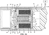
- an electrical lead 106 extends from an electronic control unit (ECU) 108 in electrical communication with the electromechanical support 10 and more particularly with an electrical map of the motor 82 which includes supply and hall sensor leads and the coil assembly 86 of the electro-mechanical brake assembly 38 can.
- ECU electronice control unit
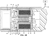
- brake 38 is moved to the "disengaged state" and motor shaft 38 rotates about axis A about planetary gear set 34 and thus lead screw 36 to drive, whereby the drive nut 62 and the extendable tube 18 are driven axially to different positions.
- the motor shaft 98 may drive the telescoping unit 16 to an extended position to open the lift door or the side door.
- the motor shaft 56 may also drive the telescoping unit 16 in a contracted position to close the lift gate or door.
- the brake 38 is normally in the "engaged state” to prevent movement of the motor shaft 56, the lead screw 36, and thus the telescoping unit 16.
- the electromechanical brake 38 When the electromechanical brake 38 is in the "engaged state" as in FIG. 4A
- the coil assembly 86 When the electromechanical brake 38 is in the "engaged state" as in FIG. 4A
- the coil assembly 86 When the door 28 is fully closed or in an open position, the coil assembly 86 is inactive due to the absence of electrical current supplied to it. off. Thus, no power or energy is supplied from the ECO 108 to the coil assembly 86 of the brake 38, and thus, the spring force exerted by the spring member 82 biases the second friction plate 80 into frictional contact with the first friction plate 78 around the first friction plate 78 and thus to prevent the motor shaft 98 from rotating about the axis A.
- the brake 38 By preventing rotation of the motor shaft 98, the brake 38 also prevents rotational movement of the planetary gear set 34 and the lead screw. Accordingly, the support 10 maintains a fixed length extending between the first and second ends 22, 26.
- a signal or command is selectively sent to the ECU 108 sent.
- a user of the vehicle 11 may initiate the sending of a signal or command to the ECU 108 to selectively release the brake 38 and thus allow the lift door 28 or door to clear a new position, such as open or closed position closed position is moved.
- a key fob, button, sensor or any other device associated with the vehicle 11 or vehicle 11 may be used to send the signal to the ECU 108.
- the ECU 108 Upon receipt of the signal, the ECU 108 provides power in the form of electrical current through the line or lines 106 to the coil assembly 86 and also to the motor 32.
- the energy requested by the ECU 108 and delivered to the motor 32 causes the motor shaft 98 and the first friction plate 78 to rotate about the axis A.
- the motor shaft 98 and the first friction plate 78 are free to rotate about the axis A.
- the motor shaft 98 thus drives the planetary gear set 34 and the lead screw 36, which then causes the drive nut 62 and the telescopic unit 16 to move along the lead screw 36 to the desired position.
- the motor shaft 98 may drive the lead screw 36 causing the drive nut 62 and associated extendable tube 18 to move along the axis A to a position in which the lift door 28 or the door is open. If the lift door 28 or door is open, the motor shaft 98 may drive the lead screw 36 causing the drive nut 62 and associated extendable tube 18 to move axially along the axis A to a position in which the lift door 28 or the door is closed.
- a signal is selectively sent from the ECU 108 to control the supply of energy through the Line 64 to the motor 32 and the coil assembly 86 to interrupt, whereby the coil assembly 86 is turned off and thus causes the magnetic force from the coil assembly 86 disappears, causing the second friction plate 80 under the tension of the spring member 82 in the Frictional engagement with the first friction plate 78 moves. Accordingly, the brake 38 is again brought into the "engaged state" to prevent rotation of the lead screw 36 and to keep the support 10 in a fixed length and thus the lifting door 28 or the side door in the desired position.
- the post 10 of the present disclosure may also be operated manually.
- the ECU 108 detects movement of feedback sensors provided along the post 10 and releases the electro-mechanical brake 38 in the same manner as in the current mode described above. If all power is lost, for example, if the vehicle battery is empty, the braking torque is limited to a maximum permitted sliding condition. This allows the lift door 28 or the door to be opened or closed with greater than normal manual forces.
Landscapes
- Engineering & Computer Science (AREA)
- General Engineering & Computer Science (AREA)
- Mechanical Engineering (AREA)
- Power-Operated Mechanisms For Wings (AREA)
- Braking Arrangements (AREA)
Applications Claiming Priority (1)
| Application Number | Priority Date | Filing Date | Title |
|---|---|---|---|
| US201562152256P | 2015-04-24 | 2015-04-24 |
Publications (1)
| Publication Number | Publication Date |
|---|---|
| EP3147441A1 true EP3147441A1 (de) | 2017-03-29 |
Family
ID=56120960
Family Applications (1)
| Application Number | Title | Priority Date | Filing Date |
|---|---|---|---|
| EP16174128.5A Withdrawn EP3147441A1 (de) | 2015-04-24 | 2016-06-13 | Elektromechanische stütze mit elektromechanischer bremse und verfahren zum erlauben und verhindern einer bewegung eines verschlusselementes eines fahrzeugs |
Country Status (4)
| Country | Link |
|---|---|
| US (2) | US10280674B2 (zh) |
| EP (1) | EP3147441A1 (zh) |
| CN (1) | CN106065752B (zh) |
| DE (1) | DE102016207415A1 (zh) |
Families Citing this family (45)
| Publication number | Priority date | Publication date | Assignee | Title |
|---|---|---|---|---|
| WO2013013313A1 (en) * | 2011-07-27 | 2013-01-31 | Magna Closures Inc. | Power swing door actuator |
| JP6173293B2 (ja) * | 2014-12-02 | 2017-08-02 | 株式会社ハイレックスコーポレーション | 伸縮駆動装置および開閉体開閉装置 |
| DE102015119457A1 (de) * | 2015-11-11 | 2017-05-11 | Brose Fahrzeugteile Gmbh & Co. Kommanditgesellschaft, Bamberg | Spindelantrieb |
| JP6632504B2 (ja) * | 2016-10-03 | 2020-01-22 | 株式会社ミツバ | 動力伝達機構、アクチュエータ、および車両用アクチュエータ |
| KR102514336B1 (ko) * | 2016-12-01 | 2023-03-24 | 워렌 인더스트리즈 엘티디. | 개선된 도어 제어 시스템(improved door control system) |
| CN108240149B (zh) * | 2016-12-26 | 2023-09-08 | 广东东箭汽车科技股份有限公司 | 一种皮卡车尾门撑杆 |
| DE102017102173A1 (de) * | 2017-02-03 | 2018-08-09 | Brose Fahrzeugteile Gmbh & Co. Kommanditgesellschaft, Bamberg | Spindelantrieb |
| US10801593B2 (en) | 2017-04-26 | 2020-10-13 | Paratech, Incorporated | Strut extender mechanism |
| JP6930221B2 (ja) * | 2017-05-30 | 2021-09-01 | 株式会社アイシン | 車両用ドア開閉装置 |
| US10774571B2 (en) | 2017-05-30 | 2020-09-15 | Magna Closures Inc. | Integrated controller with sensors for electromechanical biasing member |
| CN107035265B (zh) * | 2017-05-31 | 2018-11-16 | 芜湖莫森泰克汽车科技股份有限公司 | 一种具有缓冲功能的汽车尾门电动撑杆结构 |
| DE102017210707A1 (de) * | 2017-06-26 | 2018-12-27 | Volkswagen Aktiengesellschaft | Antriebssystem |
| DE102017115183A1 (de) * | 2017-07-06 | 2019-01-10 | Edscha Engineering Gmbh | Antriebsvorrichtung für eine Fahrzeugklappe |
| CN109263573B (zh) | 2017-07-17 | 2023-05-26 | 麦格纳覆盖件有限公司 | 用于在受控构件移动时唤醒电子控制单元的系统 |
| CN107489336B (zh) * | 2017-08-23 | 2020-05-19 | 武汉佳特轿车零部件有限公司 | 用于汽车尾门的电动开闭系统 |
| US11033678B2 (en) * | 2017-11-20 | 2021-06-15 | Agist Medical Systems, Inc. | Compact injector drive |
| JP2019094733A (ja) * | 2017-11-27 | 2019-06-20 | 株式会社ミツバ | アクチュエータ及び車両ドア開閉用アクチュエータ |
| US20190211604A1 (en) * | 2018-01-08 | 2019-07-11 | Magna Closures Inc. | Electromechanical strut with planetary gearset having an integrated flex coupling |
| US10767412B2 (en) | 2018-01-08 | 2020-09-08 | Magna Closures Inc. | Electromechanical strut with power actuator having supplemental friction control |
| DE202018101761U1 (de) * | 2018-03-28 | 2018-04-12 | Edscha Engineering Gmbh | Bremsanordnung für eine Antriebsvorrichtung |
| CN108457548B (zh) * | 2018-04-12 | 2024-05-31 | 广东东箭汽车科技股份有限公司 | 一种电磁阻尼器 |
| CN108360941B (zh) * | 2018-04-18 | 2024-05-28 | 广东东箭汽车科技股份有限公司 | 一种激光焊接式电动撑杆 |
| US11136811B2 (en) | 2018-04-20 | 2021-10-05 | Magna Closures Inc. | Connection mechanism for thin wall tube |
| CN109252782B (zh) * | 2018-11-07 | 2024-04-12 | 广东东箭汽车科技股份有限公司 | 螺母丝杠式自动门开闭机构、汽车自动门和汽车 |
| US20200165856A1 (en) * | 2018-11-28 | 2020-05-28 | Magna Closures Inc. | Counterbalance strut for vehicle closure panel lift system having an active brake and method for counterbalance strut and system control |
| DE102019103682A1 (de) * | 2019-02-13 | 2020-08-13 | Brose Fahrzeugteile Se & Co. Kommanditgesellschaft, Bamberg | Spindelantrieb zur motorischen Verstellung eines Verstellelements eines Kraftfahrzeugs |
| US11840874B2 (en) * | 2019-03-27 | 2023-12-12 | Magna Closures Inc. | Counterbalance mechanism with friction |
| DE102019111305A1 (de) | 2019-05-02 | 2020-11-05 | Kiekert Aktiengesellschaft | Aufstellvorrichtung für eine Kraftfahrzeugtür |
| JP7252058B2 (ja) * | 2019-05-27 | 2023-04-04 | 株式会社ユーシン | 車両用ドア支持装置 |
| CN112211519A (zh) * | 2019-07-09 | 2021-01-12 | 昆山麦格纳汽车系统有限公司 | 具有螺纹式连接的闭合面板平衡机构 |
| CN110566062A (zh) * | 2019-09-11 | 2019-12-13 | 有信制造(无锡)有限公司 | 一种带有可解除机械刹车系统的电动尾门执行器 |
| CN110486424A (zh) | 2019-09-19 | 2019-11-22 | 广东肇庆爱龙威机电有限公司 | 行星齿轮传动箱 |
| DE112020005399T5 (de) | 2019-11-01 | 2022-08-11 | Magna Closures Inc. | Angetriebene türeinheit, optimiert für servosteuerung |
| DE102020110214B4 (de) * | 2020-04-14 | 2023-10-12 | Edscha Engineering Gmbh | Bremsanordnung für eine Antriebsvorrichtung |
| DE102020111986A1 (de) * | 2020-05-04 | 2021-11-04 | Brose Fahrzeugteile Se & Co. Kommanditgesellschaft, Bamberg | Spindelantrieb für ein Verschlusselement eines Kraftfahrzeugs |
| US11067156B1 (en) | 2020-07-21 | 2021-07-20 | Hi-Lex Controls, Inc. | Friction brake and power strut therewith |
| US11067155B1 (en) | 2020-07-27 | 2021-07-20 | Hi-Lex Controls, Inc. | Spindle drive for curved path of movement |
| CN112065207A (zh) * | 2020-09-17 | 2020-12-11 | 广东骏驰科技股份有限公司 | 一种新型电动电撑杆 |
| CN215257364U (zh) | 2021-02-09 | 2021-12-21 | 麦格纳汽车系统(苏州)有限公司 | 一种异向异值阻尼装置及电动伸缩机构 |
| DE102022103328A1 (de) | 2021-02-22 | 2022-08-25 | Magna Closures Inc. | Verteiltes steuerungssystem für servogesteuerten türantrieb |
| TWI769855B (zh) | 2021-06-11 | 2022-07-01 | 一德金屬工業股份有限公司 | 利用即時無線供電的鎖具的解鎖方法 |
| TWI776725B (zh) * | 2021-11-03 | 2022-09-01 | 一德金屬工業股份有限公司 | 門弓器 |
| DE102022129792A1 (de) | 2021-12-14 | 2023-06-15 | Magna Closures Inc. | Verteiltes steuerungssystem für servogesteuerten türantrieb |
| DE102023103075A1 (de) | 2022-02-24 | 2023-08-24 | Magna Closures Inc. | Verteiltes steuerungssystem für servogesteuerten türantrieb |
| DE102022130487A1 (de) * | 2022-11-17 | 2024-05-23 | Brose Fahrzeugteile Se & Co. Kommanditgesellschaft, Bamberg | Antriebseinheit zur motorischen Verstellung eines Verschlusselements eines Kraftfahrzeugs |
Citations (9)
| Publication number | Priority date | Publication date | Assignee | Title |
|---|---|---|---|---|
| US6516567B1 (en) | 2001-01-19 | 2003-02-11 | Hi-Lex Corporation | Power actuator for lifting a vehicle lift gate |
| US20040084265A1 (en) | 2002-11-02 | 2004-05-06 | Suspa Holding Gmbh | Adjustable-length actuating element |
| DE202005020253U1 (de) * | 2005-12-23 | 2007-05-10 | BROSE SCHLIEßSYSTEME GMBH & CO. KG | Motorische Antriebsvorrichtung für ein bewegliches Verschlußelement eines Kraftfahrzeugs |
| DE202006001250U1 (de) * | 2006-01-25 | 2007-06-06 | BROSE SCHLIEßSYSTEME GMBH & CO. KG | Vormontierbare Antriebseinheit für ein verstellbares Funktionselement in einem Kraftfahrzeug |
| US20090200830A1 (en) * | 2004-08-06 | 2009-08-13 | Gordon Andrew Paton | Electromechanical strut |
| EP2284345A1 (de) * | 2009-07-10 | 2011-02-16 | VALEO Sicherheitssysteme GmbH | Bremsvorrichtung für eine Antriebseinrichtung zum Bewegen einer Tür und Antriebseinrichtung, die damit ausgestattet ist |
| US20120000304A1 (en) | 2007-08-06 | 2012-01-05 | Hamminga Jeffrey S | Linear drive actuator for a movable vehicle panel |
| US20150376929A1 (en) | 2014-06-27 | 2015-12-31 | Magna Closures Inc. | Electromechanical strut with integrated flex coupling and slip device and clutch/coupling assembly therefor |
| US20160144694A1 (en) | 2014-11-24 | 2016-05-26 | Magna Closures Inc. | Electromechanical strut with motor-gearbox assembly having dual stage planetary gearbox |
Family Cites Families (25)
| Publication number | Priority date | Publication date | Assignee | Title |
|---|---|---|---|---|
| DE2113275A1 (de) * | 1971-03-19 | 1972-09-21 | Zinser Textilmaschinen Gmbh | Spinn- oder Zwirnspindel |
| SE462713B (sv) * | 1988-04-27 | 1990-08-20 | Drinx Productions Ab | Doserings- och blandningsanordning |
| US20030136626A1 (en) | 2002-01-23 | 2003-07-24 | Ciaramitaro Dina A. | Magneto-rheological clutch assembly for use in an electromechanical system |
| US6927513B2 (en) * | 2002-07-01 | 2005-08-09 | Bear Linear Llc | Electromechanical screw drive actuator |
| US7566092B2 (en) | 2004-08-06 | 2009-07-28 | Magna Closures Inc. | Electromechanical strut |
| CA2514670A1 (en) | 2004-08-06 | 2006-02-06 | Magna Closures Inc. | Electromechanical strut |
| US7648189B2 (en) | 2005-10-03 | 2010-01-19 | Magna Closures Inc. | Powered actuating device for a closure panel of a vehicle |
| US8006817B2 (en) * | 2005-11-02 | 2011-08-30 | Dura Global Technologies, Llc | Power strut assembly |
| DE202005020087U1 (de) | 2005-12-07 | 2007-04-19 | BROSE SCHLIEßSYSTEME GMBH & CO. KG | Antriebsanordnung zur motorischen Verstellung einer Kraftfahrzeugtür o.dgl. |
| US20070179006A1 (en) * | 2006-01-25 | 2007-08-02 | Brose Schliesssysteme Gmbh & Co. Kg | Preassembled drive unit for an adjustable functional element in a motor vehicle |
| US7547058B2 (en) | 2006-05-15 | 2009-06-16 | Ford Global Technologies, Llc | System and method for operating an automotive liftgate |
| DE102006027857B4 (de) | 2006-06-16 | 2009-11-26 | Stabilus Gmbh | Klappenantrieb |
| US20070296243A1 (en) * | 2006-06-26 | 2007-12-27 | Guido Borrmann | Adjusting system of a motor vehicle for the adjustment of a closing part for the closure of an opening of a motor vehicle body |
| GB0618572D0 (en) * | 2006-09-21 | 2006-11-01 | Goodrich Actuation Systems Ltd | Actuator |
| EP2193283B1 (en) * | 2007-09-19 | 2013-03-20 | Ab Skf | Locking device |
| DE102008009898B4 (de) | 2007-11-13 | 2010-07-15 | Stabilus Gmbh | Klappenöffnungs- und -schließsystem |
| EP2199513B1 (en) * | 2008-12-19 | 2013-05-01 | Valeo Sicherheitssysteme GmbH | Adjusting device having a spindle drive |
| US20120098368A1 (en) * | 2009-05-14 | 2012-04-26 | Yuehua Xiong | Electrical push device |
| CN101888135B (zh) * | 2009-05-14 | 2013-08-28 | 长沙三占惯性制动有限公司 | 一种电动推动装置 |
| DE102009042456B4 (de) * | 2009-09-23 | 2013-06-27 | Stabilus Gmbh | Antriebseinrichtung |
| DE102009058503B4 (de) | 2009-12-16 | 2021-02-25 | Dr. Ing. H.C. F. Porsche Aktiengesellschaft | Einstellbare Heckklappenabstützung |
| US20110302841A1 (en) | 2010-06-14 | 2011-12-15 | Hangzhou Sanford Tools Co., Ltd. | Swing gate operator |
| JP2015140598A (ja) * | 2014-01-29 | 2015-08-03 | アイシン精機株式会社 | 回転停止保持切換装置 |
| CN204199942U (zh) * | 2014-10-16 | 2015-03-11 | 乔明齐 | 一种汽车后备箱自动感应开启和关闭装置 |
| US20160312517A1 (en) * | 2015-04-22 | 2016-10-27 | Ford Global Technologies, Llc | Vehicle and method of opening and closing a door of the vehicle |
-
2016
- 2016-04-18 US US15/131,826 patent/US10280674B2/en active Active
- 2016-04-21 CN CN201610251382.4A patent/CN106065752B/zh active Active
- 2016-04-29 DE DE102016207415.6A patent/DE102016207415A1/de active Pending
- 2016-06-13 EP EP16174128.5A patent/EP3147441A1/de not_active Withdrawn
-
2019
- 2019-04-04 US US16/374,779 patent/US10822856B2/en active Active
Patent Citations (9)
| Publication number | Priority date | Publication date | Assignee | Title |
|---|---|---|---|---|
| US6516567B1 (en) | 2001-01-19 | 2003-02-11 | Hi-Lex Corporation | Power actuator for lifting a vehicle lift gate |
| US20040084265A1 (en) | 2002-11-02 | 2004-05-06 | Suspa Holding Gmbh | Adjustable-length actuating element |
| US20090200830A1 (en) * | 2004-08-06 | 2009-08-13 | Gordon Andrew Paton | Electromechanical strut |
| DE202005020253U1 (de) * | 2005-12-23 | 2007-05-10 | BROSE SCHLIEßSYSTEME GMBH & CO. KG | Motorische Antriebsvorrichtung für ein bewegliches Verschlußelement eines Kraftfahrzeugs |
| DE202006001250U1 (de) * | 2006-01-25 | 2007-06-06 | BROSE SCHLIEßSYSTEME GMBH & CO. KG | Vormontierbare Antriebseinheit für ein verstellbares Funktionselement in einem Kraftfahrzeug |
| US20120000304A1 (en) | 2007-08-06 | 2012-01-05 | Hamminga Jeffrey S | Linear drive actuator for a movable vehicle panel |
| EP2284345A1 (de) * | 2009-07-10 | 2011-02-16 | VALEO Sicherheitssysteme GmbH | Bremsvorrichtung für eine Antriebseinrichtung zum Bewegen einer Tür und Antriebseinrichtung, die damit ausgestattet ist |
| US20150376929A1 (en) | 2014-06-27 | 2015-12-31 | Magna Closures Inc. | Electromechanical strut with integrated flex coupling and slip device and clutch/coupling assembly therefor |
| US20160144694A1 (en) | 2014-11-24 | 2016-05-26 | Magna Closures Inc. | Electromechanical strut with motor-gearbox assembly having dual stage planetary gearbox |
Also Published As
| Publication number | Publication date |
|---|---|
| US20160312514A1 (en) | 2016-10-27 |
| US10822856B2 (en) | 2020-11-03 |
| CN106065752B (zh) | 2020-11-24 |
| DE102016207415A1 (de) | 2016-10-27 |
| US10280674B2 (en) | 2019-05-07 |
| CN106065752A (zh) | 2016-11-02 |
| US20190249477A1 (en) | 2019-08-15 |
Similar Documents
| Publication | Publication Date | Title |
|---|---|---|
| EP3147441A1 (de) | Elektromechanische stütze mit elektromechanischer bremse und verfahren zum erlauben und verhindern einer bewegung eines verschlusselementes eines fahrzeugs | |
| DE102019132231A1 (de) | Ausgleichsstrebe für fahrzeug-verschlusspaneelhubsystem mit einer aktiven bremse und verfahren zur für eineausgleichsstrebe und systemsteuerung | |
| DE112008002124B4 (de) | Linearantriebsaktuator für ein bewegliches Fahrzeugpaneel | |
| EP1795685B1 (de) | Antriebsanordnung zur motorischen Verstellung einer Kraftfahrzeugtür o.dgl. | |
| DE102019114170A1 (de) | Angetriebenes stellglied mit selbstausrastender kupplungseinheit | |
| EP2914864B1 (de) | Antriebseinrichtung | |
| DE102007020826B4 (de) | Antriebseinrichtung | |
| EP2457754B1 (de) | Fahrwerkaktuator | |
| DE102015009717B4 (de) | Ein- und ausfahrbare Stütze für schwenkbare Fahrzeugabdeckung | |
| DE102019100202A1 (de) | Elektromechanische Strebe angetriebenem Stellglied mitzusätzlicher Reibungssteuerung | |
| DE68902940T2 (de) | Ein stellantrieb. | |
| EP2098743A1 (de) | Stellmechanismus zum Ein- und Ausrücken einer Trennkupplung mit drehbarem Kurvensegment | |
| EP1881235A2 (de) | Von einem Antrieb antreibbarer Spindelantrieb für ein bewegbares Bauteil | |
| DE102008059989A1 (de) | Kupplungsantrieb | |
| DE102015220920B4 (de) | Baugruppe mit einer Reibeinrichtung | |
| DE102019209680A1 (de) | Aktuatoreinheit für ein lenkrad eines fahrzeugs | |
| DE10350698B4 (de) | Kupplungsmechanismus | |
| DE102021120210A1 (de) | Antriebsvorrichtung für eine verstellbare Fahrzeugklappe | |
| DE102007039823B4 (de) | Antriebseinrichtung | |
| DE102009036872A1 (de) | Türeinheit | |
| WO2018188796A1 (de) | Reibschlussanordnung für einen antrieb eines verschlusselements eines kraftfahrzeugs | |
| DE102019111720A1 (de) | Elektromechanischer Parksperrenaktuator | |
| DE102006008525A1 (de) | Vorrichtung zum Befestigen einer Fahrzeugtür | |
| DE60124308T2 (de) | Federbremsstellglied | |
| DE102020204473A1 (de) | Verstellantrieb für eine Lenksäule und Lenksäule für ein Kraftfahrzeug |
Legal Events
| Date | Code | Title | Description |
|---|---|---|---|
| PUAI | Public reference made under article 153(3) epc to a published international application that has entered the european phase |
Free format text: ORIGINAL CODE: 0009012 |
|
| AK | Designated contracting states |
Kind code of ref document: A1 Designated state(s): AL AT BE BG CH CY CZ DE DK EE ES FI FR GB GR HR HU IE IS IT LI LT LU LV MC MK MT NL NO PL PT RO RS SE SI SK SM TR |
|
| AX | Request for extension of the european patent |
Extension state: BA ME |
|
| STAA | Information on the status of an ep patent application or granted ep patent |
Free format text: STATUS: THE APPLICATION IS DEEMED TO BE WITHDRAWN |
|
| 18D | Application deemed to be withdrawn |
Effective date: 20170930 |