EP3145646B1 - Behandlungsvorrichtung und verfahren für werkstücke mit einer elektrischen behandlungseinheit - Google Patents
Behandlungsvorrichtung und verfahren für werkstücke mit einer elektrischen behandlungseinheit Download PDFInfo
- Publication number
- EP3145646B1 EP3145646B1 EP15724184.5A EP15724184A EP3145646B1 EP 3145646 B1 EP3145646 B1 EP 3145646B1 EP 15724184 A EP15724184 A EP 15724184A EP 3145646 B1 EP3145646 B1 EP 3145646B1
- Authority
- EP
- European Patent Office
- Prior art keywords
- coupling element
- shaft
- treatment
- coupling
- treatment device
- Prior art date
- Legal status (The legal status is an assumption and is not a legal conclusion. Google has not performed a legal analysis and makes no representation as to the accuracy of the status listed.)
- Active
Links
Images


Classifications
-
- B—PERFORMING OPERATIONS; TRANSPORTING
- B08—CLEANING
- B08B—CLEANING IN GENERAL; PREVENTION OF FOULING IN GENERAL
- B08B15/00—Preventing escape of dirt or fumes from the area where they are produced; Collecting or removing dirt or fumes from that area
- B08B15/02—Preventing escape of dirt or fumes from the area where they are produced; Collecting or removing dirt or fumes from that area using chambers or hoods covering the area
-
- B—PERFORMING OPERATIONS; TRANSPORTING
- B05—SPRAYING OR ATOMISING IN GENERAL; APPLYING FLUENT MATERIALS TO SURFACES, IN GENERAL
- B05B—SPRAYING APPARATUS; ATOMISING APPARATUS; NOZZLES
- B05B13/00—Machines or plants for applying liquids or other fluent materials to surfaces of objects or other work by spraying, not covered by groups B05B1/00 - B05B11/00
- B05B13/02—Means for supporting work; Arrangement or mounting of spray heads; Adaptation or arrangement of means for feeding work
- B05B13/04—Means for supporting work; Arrangement or mounting of spray heads; Adaptation or arrangement of means for feeding work the spray heads being moved during spraying operation
- B05B13/0405—Means for supporting work; Arrangement or mounting of spray heads; Adaptation or arrangement of means for feeding work the spray heads being moved during spraying operation with reciprocating or oscillating spray heads
-
- B—PERFORMING OPERATIONS; TRANSPORTING
- B05—SPRAYING OR ATOMISING IN GENERAL; APPLYING FLUENT MATERIALS TO SURFACES, IN GENERAL
- B05B—SPRAYING APPARATUS; ATOMISING APPARATUS; NOZZLES
- B05B13/00—Machines or plants for applying liquids or other fluent materials to surfaces of objects or other work by spraying, not covered by groups B05B1/00 - B05B11/00
- B05B13/02—Means for supporting work; Arrangement or mounting of spray heads; Adaptation or arrangement of means for feeding work
- B05B13/04—Means for supporting work; Arrangement or mounting of spray heads; Adaptation or arrangement of means for feeding work the spray heads being moved during spraying operation
- B05B13/0421—Means for supporting work; Arrangement or mounting of spray heads; Adaptation or arrangement of means for feeding work the spray heads being moved during spraying operation with rotating spray heads
-
- B—PERFORMING OPERATIONS; TRANSPORTING
- B05—SPRAYING OR ATOMISING IN GENERAL; APPLYING FLUENT MATERIALS TO SURFACES, IN GENERAL
- B05B—SPRAYING APPARATUS; ATOMISING APPARATUS; NOZZLES
- B05B13/00—Machines or plants for applying liquids or other fluent materials to surfaces of objects or other work by spraying, not covered by groups B05B1/00 - B05B11/00
- B05B13/02—Means for supporting work; Arrangement or mounting of spray heads; Adaptation or arrangement of means for feeding work
- B05B13/04—Means for supporting work; Arrangement or mounting of spray heads; Adaptation or arrangement of means for feeding work the spray heads being moved during spraying operation
- B05B13/0463—Installation or apparatus for applying liquid or other fluent material to moving work of indefinite length
- B05B13/0468—Installation or apparatus for applying liquid or other fluent material to moving work of indefinite length with reciprocating or oscillating spray heads
-
- B—PERFORMING OPERATIONS; TRANSPORTING
- B05—SPRAYING OR ATOMISING IN GENERAL; APPLYING FLUENT MATERIALS TO SURFACES, IN GENERAL
- B05B—SPRAYING APPARATUS; ATOMISING APPARATUS; NOZZLES
- B05B13/00—Machines or plants for applying liquids or other fluent materials to surfaces of objects or other work by spraying, not covered by groups B05B1/00 - B05B11/00
- B05B13/02—Means for supporting work; Arrangement or mounting of spray heads; Adaptation or arrangement of means for feeding work
- B05B13/04—Means for supporting work; Arrangement or mounting of spray heads; Adaptation or arrangement of means for feeding work the spray heads being moved during spraying operation
- B05B13/0463—Installation or apparatus for applying liquid or other fluent material to moving work of indefinite length
- B05B13/0484—Installation or apparatus for applying liquid or other fluent material to moving work of indefinite length with spray heads having a circular motion, e.g. being attached to a rotating supporting element
- B05B13/0489—Installation or apparatus for applying liquid or other fluent material to moving work of indefinite length with spray heads having a circular motion, e.g. being attached to a rotating supporting element around the moving work
-
- B—PERFORMING OPERATIONS; TRANSPORTING
- B05—SPRAYING OR ATOMISING IN GENERAL; APPLYING FLUENT MATERIALS TO SURFACES, IN GENERAL
- B05B—SPRAYING APPARATUS; ATOMISING APPARATUS; NOZZLES
- B05B16/00—Spray booths
-
- B—PERFORMING OPERATIONS; TRANSPORTING
- B08—CLEANING
- B08B—CLEANING IN GENERAL; PREVENTION OF FOULING IN GENERAL
- B08B3/00—Cleaning by methods involving the use or presence of liquid or steam
- B08B3/02—Cleaning by the force of jets or sprays
- B08B3/024—Cleaning by means of spray elements moving over the surface to be cleaned
-
- B—PERFORMING OPERATIONS; TRANSPORTING
- B08—CLEANING
- B08B—CLEANING IN GENERAL; PREVENTION OF FOULING IN GENERAL
- B08B3/00—Cleaning by methods involving the use or presence of liquid or steam
- B08B3/04—Cleaning involving contact with liquid
- B08B3/10—Cleaning involving contact with liquid with additional treatment of the liquid or of the object being cleaned, e.g. by heat, by electricity or by vibration
-
- B—PERFORMING OPERATIONS; TRANSPORTING
- B08—CLEANING
- B08B—CLEANING IN GENERAL; PREVENTION OF FOULING IN GENERAL
- B08B3/00—Cleaning by methods involving the use or presence of liquid or steam
- B08B3/04—Cleaning involving contact with liquid
- B08B3/10—Cleaning involving contact with liquid with additional treatment of the liquid or of the object being cleaned, e.g. by heat, by electricity or by vibration
- B08B3/108—Cleaning involving contact with liquid with additional treatment of the liquid or of the object being cleaned, e.g. by heat, by electricity or by vibration by lowering and raising the level of the cleaning liquid
-
- B—PERFORMING OPERATIONS; TRANSPORTING
- B08—CLEANING
- B08B—CLEANING IN GENERAL; PREVENTION OF FOULING IN GENERAL
- B08B3/00—Cleaning by methods involving the use or presence of liquid or steam
- B08B3/04—Cleaning involving contact with liquid
- B08B3/10—Cleaning involving contact with liquid with additional treatment of the liquid or of the object being cleaned, e.g. by heat, by electricity or by vibration
- B08B3/12—Cleaning involving contact with liquid with additional treatment of the liquid or of the object being cleaned, e.g. by heat, by electricity or by vibration by sonic or ultrasonic vibrations
-
- B—PERFORMING OPERATIONS; TRANSPORTING
- B08—CLEANING
- B08B—CLEANING IN GENERAL; PREVENTION OF FOULING IN GENERAL
- B08B5/00—Cleaning by methods involving the use of air flow or gas flow
- B08B5/02—Cleaning by the force of jets, e.g. blowing-out cavities
-
- B—PERFORMING OPERATIONS; TRANSPORTING
- B08—CLEANING
- B08B—CLEANING IN GENERAL; PREVENTION OF FOULING IN GENERAL
- B08B7/00—Cleaning by methods not provided for in a single other subclass or a single group in this subclass
- B08B7/0064—Cleaning by methods not provided for in a single other subclass or a single group in this subclass by temperature changes
- B08B7/0071—Cleaning by methods not provided for in a single other subclass or a single group in this subclass by temperature changes by heating
-
- B—PERFORMING OPERATIONS; TRANSPORTING
- B08—CLEANING
- B08B—CLEANING IN GENERAL; PREVENTION OF FOULING IN GENERAL
- B08B7/00—Cleaning by methods not provided for in a single other subclass or a single group in this subclass
- B08B7/02—Cleaning by methods not provided for in a single other subclass or a single group in this subclass by distortion, beating, or vibration of the surface to be cleaned
- B08B7/026—Using sound waves
- B08B7/028—Using ultrasounds
-
- B—PERFORMING OPERATIONS; TRANSPORTING
- B08—CLEANING
- B08B—CLEANING IN GENERAL; PREVENTION OF FOULING IN GENERAL
- B08B7/00—Cleaning by methods not provided for in a single other subclass or a single group in this subclass
- B08B7/04—Cleaning by methods not provided for in a single other subclass or a single group in this subclass by a combination of operations
-
- B—PERFORMING OPERATIONS; TRANSPORTING
- B05—SPRAYING OR ATOMISING IN GENERAL; APPLYING FLUENT MATERIALS TO SURFACES, IN GENERAL
- B05B—SPRAYING APPARATUS; ATOMISING APPARATUS; NOZZLES
- B05B13/00—Machines or plants for applying liquids or other fluent materials to surfaces of objects or other work by spraying, not covered by groups B05B1/00 - B05B11/00
- B05B13/02—Means for supporting work; Arrangement or mounting of spray heads; Adaptation or arrangement of means for feeding work
- B05B13/04—Means for supporting work; Arrangement or mounting of spray heads; Adaptation or arrangement of means for feeding work the spray heads being moved during spraying operation
- B05B13/0442—Installation or apparatus for applying liquid or other fluent material to separate articles rotated during spraying operation
-
- B—PERFORMING OPERATIONS; TRANSPORTING
- B05—SPRAYING OR ATOMISING IN GENERAL; APPLYING FLUENT MATERIALS TO SURFACES, IN GENERAL
- B05B—SPRAYING APPARATUS; ATOMISING APPARATUS; NOZZLES
- B05B13/00—Machines or plants for applying liquids or other fluent materials to surfaces of objects or other work by spraying, not covered by groups B05B1/00 - B05B11/00
- B05B13/02—Means for supporting work; Arrangement or mounting of spray heads; Adaptation or arrangement of means for feeding work
- B05B13/04—Means for supporting work; Arrangement or mounting of spray heads; Adaptation or arrangement of means for feeding work the spray heads being moved during spraying operation
- B05B13/0447—Installation or apparatus for applying liquid or other fluent material to conveyed separate articles
Definitions
- Embodiments of the present invention relate to a treatment device for workpieces.
- treatment devices having a treatment chamber, a part-receiving device arranged in the treatment chamber, and a nozzle device arranged in the treatment chamber, which serves to deliver a treatment medium.
- This treatment medium is a liquid medium for cleansing treatment or a gaseous medium for cleansing and / or drying treatment.
- Such treatment devices are for example in the EP 0 507 294 B1 , the WO 98/45059 A1 or the EP 2 156 905 A1 described.
- EP 2 156 905 A1 describes a treatment device for workpieces.
- EP 0 507 294 B1 a system for cleaning and degreasing of workpieces is shown.
- DE 197 14 603 C1 shows a method and apparatus for cleaning workpieces.
- EP 1 346 779 A2 describes a device for receiving a workpiece carrier and for supplying a first and second medium.
- DE 196 35 867 A1 shows an arrangement for actuating a switching device of a gear change transmission and for engaging and disengaging a main clutch.
- Object of the present invention is therefore to provide a treatment device for workpieces having an electrical treatment unit in a treatment chamber, and in which an electrical supply to the treatment unit is ensured in a simple and relatively inexpensive manner to realize, and a method of operation Such a treatment device to provide.
- the treatment apparatus comprises a treatment chamber, a shaft extending through a wall of the treatment chamber into the treatment chamber and rotatably supported, an electric treatment unit fixed to the shaft, and a power supply having a first supply line, an electrical coupling, a second supply line and a power supply operating unit.
- the electrical coupling comprises a first coupling element fastened to the shaft outside the treatment chamber and a second coupling element.
- the first supply line connects the electrical treatment unit to the first coupling part, and the second supply line is connected to the second coupling part.
- the operating unit is configured to actuate the clutch to bring the second coupling part in contact with the first coupling part or to release the second coupling part from the first coupling part.
- a second embodiment relates to a method for operating such a treatment device.
- the method comprises operating the treatment device in a first operating state, in which the second coupling part is in contact with the first coupling part, or in a second operating state, in which the second coupling part is detached from the first coupling part.
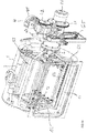
- FIGs 1A-1B show an embodiment of a treatment device for workpieces, which has a treatment chamber 1 and a rotatable in the treatment chamber 1 arranged electrical treatment unit 3.
- Figure 1A shows a perspective view of the treatment chamber 1 (which is shown in phantom) and further, hereinafter explained elements of the treatment device.
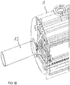
- FIG. 1B shows a perspective view of a part of the treatment chamber 1 from a different angle.
- the treatment device comprises a shaft 2, which extends through a wall of the treatment chamber 1 into the treatment chamber and which is rotatably mounted relative to the treatment chamber 1.
- the treatment chamber 1 is in the illustrated embodiment is substantially cylindrical, and the shaft 2 is inserted into the treatment chamber 1 at an end face of the cylindrical processing chamber 1. This is just one example.
- the treatment chamber 1 could also have a different chamber geometry and could, for example, be spherical.
- the treatment chamber 1 For feeding the treatment chamber 1 with workpieces to be treated, the treatment chamber 1 has a feed opening 11.
- This feed opening 11 is located in the illustrated embodiment on a side wall of the treatment chamber 1, which is substantially perpendicular to the end wall, via which the shaft 2 is guided into the treatment chamber 1.
- a closure (cover), with which the feed opening 11 can be closed, is not shown in the figures.
- the closure is designed to seal the feed opening 11 in a watertight and pressure-tight manner, thereby hermetically sealing the treatment chamber 1 for the treatment operation.
- Pressure-tight in this context means that the closure in the closed state, an overpressure (compared to the ambient pressure outside the treatment chamber 1), for example, several bar (2 bar, 5 bar or more) or a negative pressure, for example, to approximately 0 bar, resists.
- the treatment chamber 1 comprises seals (not shown) in the region in which the shaft 2 is guided through the chamber wall. These seals are designed according to the closure to close the treatment chamber 1 water and pressure-tight.
- a part receiving 12 which serves to hold parts to be treated during the treatment process.
- the part holder 12 is adapted to receive baskets in which workpieces to be treated are loose (as bulk material).
- the part receiver 12 is adapted to receive individual large workpieces, such as engine blocks.
- the part holder 12 may comprise rollers 13, which facilitate a "retraction” and “extension” of the workpiece baskets or the workpieces via the feed opening 11 into the treatment chamber 1.
- the part holder 12 is rotatably mounted relative to the treatment chamber 1.
- the treatment device 1 comprises a further shaft 13 (cf. FIG. 1B ).
- This further shaft 13 may be guided on a chamber wall in the treatment chamber 1, which is opposite to the chamber wall, on which the shaft 2 is guided into the treatment chamber 1.
- This shaft 13 can be driven by a motor.
- Such a rotatably arranged part receptacle 12 is basically known, so that the explanation of further details of this part receptacle, such as the associated drive device, can be dispensed with here.
- the shaft 2 is driven by an electric drive device 4.
- This drive device 4 includes, for example, an electric motor 41 and a transmission, of which in Figure 1A a gear 42 is shown.
- the drive device engages, for example, on a toothed wheel 21 attached to the shaft 2 and frictionally connected to the shaft 2.
- the drive assembly 4 may also include a mounting plate 43 to which the motor 41 is attached.
- the shaft 2 is guided through an opening (not shown) of the mounting plate 43.
- the mounting plate 43 may be attached in a manner not shown on a housing (not shown) of the treatment device. This enclosure surrounds all of the Figure 1A shown components of the treatment device and carries them.
- the electrical treatment unit 3 comprises, for example, an ultrasound transmitter which is designed, when switched on, to ultrasound waves in a surrounding area Medium, such as a treatment liquid to produce.
- the electrical treatment unit 3 comprises two rod-shaped and substantially mutually parallel ultrasonic generator 3A, 3B.
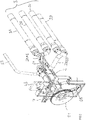
- FIG. 2 shows a further embodiment of a treatment device, wherein in FIG. 2 the treatment chamber 1 is not shown.
- the electrical treatment unit 3 comprises four such rod-shaped ultrasound transmitters 3A-3D.
- the provision of multiple ultrasound transmitters is just one example.
- the provision of rod-shaped ultrasound transmitters is just one example. Other types of ultrasound transmitters could be used.
- the rod-shaped ultrasound transmitters 3A-3B and 3A-3D run essentially parallel to the shaft 2 to which they are attached.
- connecting elements 31AB, 31CD in FIG. 2
- These connecting elements 31AB, 31CD are attached to the shaft 2 facing ends on the shaft 2, for example by screw.
- the ultrasound transmitters 3A-3D are fastened.
- An electrical treatment unit with ultrasonic generators such as those in the Figures 1A and 2 illustrated electrical treatment unit 3, is only one example of an electrical treatment unit.
- an electrical treatment unit with ultrasound transmitters or in addition to such an electrical treatment unit with ultrasound transmitters, other types of electrical treatment units could also be present in the interior of the treatment chamber 1 be attached to the shaft 2.
- An “electrical treatment unit” is understood to mean an electrical treatment unit for whose operation electrical energy (current) is required.
- Such an electrical treatment unit is for example also a treatment unit with an electric heating element or with an electrically adjustable nozzle.
- the power is used to generate heat that is released to the environment in the treatment chamber.
- an electrically adjustable nozzle the power is used to adjust or tilt the nozzle or the like.
- the nozzle is for example a nozzle for cleaning fluid or for a gaseous medium, such as air.
- a nozzle can have any type of drive powered by electrical power, such as a drive with a piezoelectric element, a transmission, a hydraulic system or the like.
- the treatment apparatus comprises a power supply arrangement.
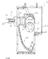
- the Figures 3A-3C illustrate an embodiment of such a power supply arrangement 6. Parts of this power supply arrangement 6 are also in the Figures 1A and 2 shown.
- the power supply arrangement comprises an electrical coupling with a first coupling element 63 fastened to the shaft 2 outside the treatment chamber 1 and a second coupling element 64, at least one first supply line 61, at least one second supply line 62 and an actuating unit 7 for the electrical coupling 63, 64
- At least one first supply line 61 connects the electrical treatment unit 3 to the first coupling element 63.
- FIG. 2 shows two first supply lines, namely a respective first supply line for one of the ultrasound transmitters 3A, 3B.
- First supply lines for the ultrasonic encoders 3C, 3D are out of the picture according to FIG. 2 , Referring to FIG. 2 the at least one first supply line 61 is at least partially guided within the shaft 2.
- the shaft 2 has an axially extending cable channel 22, which in FIG. 2 is shown cut open.
- This cable channel 22, which in the example receives two first supply lines, extends from outside the treatment chamber (which is in FIG FIG. 2 not shown) within the shaft 2 into the treatment chamber.
- the first supply line 61 emerges within the treatment chamber 1 from the cable channel 22 of the shaft 2 and is guided from there to the attached to the shaft 2 treatment unit 3.
- the illustrated at least one first supply line 61 extends within the connecting part 31AB, which is fixed to the shaft 2, to the associated ultrasonic generator 3A, 3B.
- the least a first supply line 61 extends from the cable channel 22 to the first coupling part 63, which is fastened to the shaft 1 outside the treatment chamber 1.
- the course of the first supply line 61 from the cable channel of the shaft 2 to the first coupling element 63 is in the FIGS. 3A and 3B shown.
- FIG. 3C shows the power supply arrangement without the first and second supply lines 61, 62.
- the power supply arrangement 6 may have a housing 66 in which the first coupling element 63, the second coupling element 64, the portion of the first supply line 61 arranged between the first coupling element 63 and the cable channel and the second supply line 62 are arranged.
- This housing 66 protects the aforementioned components of the power supply assembly 6 from dirt and moisture during operation. From this housing 66 are in the Figures 3A-3C a back wall and side walls shown. A front cover is not shown in the figure. The rear wall has a recess through which the shaft 2 extends. The cover, not shown, of the housing 66 has a corresponding recess on.
- a seal is provided in the region of the recesses of the rear wall and the cover, which prevents the penetration of moisture and dirt into the housing 66 in the region of the shaft 2.
- the housing 66 may be attached to the previously described mounting plate 43 (see also FIG Figure 1A ) be attached.
- the second supply line 62 is inserted at a cable inlet 67 in the housing 66.
- the second supply line 62 is connected to a power source (not shown).
- the second supply line 62 may extend outside the housing 66 to the power source.
- the power source is a power source suitable for the electrical supply of the treatment unit 3.
- the type of power source is thus dependent on the type of electrical treatment unit 3.
- the power source is a high-frequency generator, which is adapted to generate a suitable for driving the ultrasonic generator 3A-3D high-frequency signal. This high-frequency signal supplies the electrical treatment unit 3 via the at least one second supply line 62, the coupling 63, 64 and the at least one first supply line 61 when the first and the second coupling element 63, 64 are coupled together.
- the coupling In the coupled state, that is, when the first coupling element 63 is coupled to the second coupling element 64 of the coupling, the coupling provides an electrically conductive connection between the first supply line 61 and the second supply line 62.
- the coupling with the two coupling elements 63, 64 may be a conventional electrical coupling, which is tuned to the particular application, ie is suitable to electrically conductively connect the two supply lines 61, 62 for supplying the treatment unit 3.
- FIG. 3A shows the coupling elements 63, 64 in coupled (electrically interconnected) state and FIG. 3B shows the two coupling elements 63, 64 in decoupled (electrically separated from each other) state.
- the treatment device For coupling or decoupling of the two coupling elements 63, 64, the treatment device has an actuating unit 7.
- This actuating unit 7 comprises an actuating element 71 which can be brought into frictional connection with the second coupling element 64 in order to connect the second coupling element 64 to the first coupling element 63 or to detach the second coupling element 64 from the first coupling element 63.
- the production of the non-positive connection between the actuating element 71 and the second coupling element 64 by using magnetic forces it is provided that the actuating element 71 or the second coupling element 64 have an electromagnet, and that the respective other of these two components has a magnetic counterpart, on which the electromagnet can act.
- the actuating element 71 comprises an electromagnet and the second coupling element 64 comprises on a side facing away from the first coupling element 63 a magnetic counterpart 69, on which the actuating element 71 can engage with the electromagnet.
- the magnetic counterpart 69 comprises a magnetic material, such as a magnetic metal.
- the solenoid Via this control line 72, the solenoid is either activated or deactivated. In activated State, the solenoid can be frictionally associated with the magnetic counterpart 69 on the second coupling element 64 in connection.
- the actuating unit 7 comprises a linear drive 73 on which the actuating element 71 is attached.
- the linear drive 73 is designed to move the actuating element 71 linearly in order to be able to bring the actuating element 71 into contact with the second coupling element 64 and thus actuate the second coupling element 64, that is to say withdraw it from the first coupling element 63 or with the second coupling element 63 to bring into contact.
- the linear drive 73 includes, for example, a pneumatic cylinder or a linear electric motor. The supply or control of the linear drive 73 via a further supply line 74th
- the at least one second supply line 62 within the housing 66 forms a cable loop which, when the first and second coupling elements 63, 64 are coupled together, allows rotation of the shaft 2 without tearing or otherwise damaging the second supply line 62.
- the second supply line 62 may be guided within the housing 66 in a cable train 65.
- the extent to which the shaft 2 can rotate with coupled clutch 63, 64, without the clutch 63, 64 solves itself or the second supply line 62 breaks off, is dependent on the length of the second supply line 62 within the housing 66, that is dependent on the line reserve of the second supply line 62.
- the second supply line 62 is dimensioned so that the shaft 2 with coupled coupling 63, 64 has a rotation range of 180 ° maximum, 270 ° maximum, 360 ° maximum, or even 720 ° maximum.
- the "rotation range” denotes a Angular range between a first endpoint and a second endpoint of the shaft.
- the "first end point” refers to an angular position to which the coupled shaft shaft 2 can be rotated in a first direction with no risk of damage to the power supply assembly
- the second end point refers to an angular position of the shaft 2, to which the shaft 2 can be rotated in a direction opposite to the first rotational direction of the second rotational direction without the risk of damage to the power supply arrangement.
- FIGS. 3A and 3B show the shaft 2 in an angular position at which the actuator unit 7, the two coupling elements 63, 64 couple or decouple from each other.
- the shaft 2 can be rotated in a first direction, which in the example corresponds to the clockwise direction, a piece, without the risk of tearing off the second supply line 62.
- the cable loop of the second supply line 62 below the shaft 2 then shortens and the second supply line wraps around the shaft 2.
- An optional clamping element 68 which is displaceable in the vertical direction in the example, holds the second supply line 62 in this case stretched or keeps the loop upright.
- the shaft 2 can be rotated clockwise by up to 360 °.
- the shaft 2 can also be rotated in the example by 360 °, without the risk of tearing down the supply line 62.
- the shaft can therefore be rotated in both directions by 360 °, ie by +/- 360 °.
- the rotation range is thus 720 °, since the two end points are 720 ° apart.
- the further supply line 62 is inserted in the illustrated example on a side wall in the housing 66.
- the actuating unit 7 is located on one of the first side wall opposite side wall of the housing 66. This is just one example.
- the introduction of the second supply line 62 into the housing 6 can take place at any point. Decisive for the permissible rotational range of the shaft 2 with coupled coupling is the existing within the housing 66 cable reserve of the second supply line 62, so the length of the second supply line 62 within the housing 66. The longer this supply line 62, the greater is the range of rotation.
- the coupling with the two coupling elements 63, 64 may be a conventional electrical coupling, which ensures an electrically conductive connection between the two supply lines 61, 62.
- one of the two coupling elements 63, 64 may, for example, comprise contact pins which, in the coupled state, plug into corresponding sockets of the other coupling element.
- both coupling elements 63, 64 have contacts which are designed as spring contacts.
- a mechanical connection between the two coupling elements 63, 64, which prevents an automatic release of the coupling can be ensured in different ways, such as by clamping elements, spring elements, or the like.
- one of the two coupling elements 63, 64 has a permanent magnet on a contact surface facing the respective other coupling element, which in the coupled state of the coupling elements 63, 64 is non-positively connected to a magnetic counterpart of the respective other coupling element to hold the two coupling elements 63, 64 together in the coupled state.
- FIGS. 4A and 4B show respective plan views of a contact surface of the first coupling element 63 (FIG. FIG. 4A ) and the second coupling element 64 (FIG. FIG. 4B ) according to an example.
- each of the coupling elements 63, 64 includes four contacts 631-634 and 641-644, respectively.
- Each contact element of a coupling element has a corresponding contact element on the respective other coupling element and is in electrical contact with this, when the two coupling elements 63, 64 are coupled.
- the individual contact elements 631-634 or 641-644 can be designed as conventional electrical contacts, such as spring contacts. It is also possible to realize one of the corresponding contacts as a contact pin and the other of the corresponding contacts as a contact socket.
- the number of contact elements is arbitrary and dependent on the respective purpose or the number of electrical consumers to be supplied, and thus not limited to four.
- At least one of the two coupling elements 63, 64 has at the contact surface a permanent magnet, which engages in the coupled state on a magnetic counterpart of the respective other coupling element 63, 64.
- the permanent magnet and the magnetic counterpart are in the FIGS. 4A and 4B denoted by the reference numerals 635, 645. These are arranged in the illustrated embodiment in an annular manner around the contacts 631-634 or 641-644. This is just one example. Any other geometry is also possible.
- a permanent magnet is present.
- This permanent magnet corresponds either in FIG. 4A the element designated by the reference numeral 635 or in FIG FIG. 4B the element designated by reference numeral 645.
- the counterpart then consists of a magnetic material, such as a magnetic metal.
- a permanent magnet to be provided on each of the two coupling elements 63, 64, wherein these magnets are arranged on the contact surfaces in such a way that the permanent magnets are in contact with each other at the contact surfaces, ie at the surfaces which are in contact with each other in coupled coupling, have opposite magnetic poles, so that the permanent magnets attract each other.
- the electromagnet of the actuating element 7 and the magnetic counterpart 69 on the second coupling element 64 are dimensioned such that the actuating element 7 is capable of the second coupling element 64 against the magnetic force caused by the at least one permanent magnet and the magnetic counterpart of the coupling elements 63, 64 to solve each other.
- the rotational range of the shaft 2 is coupled coupled clutch 63, 64 in the manner previously explained.
- the shaft 2 can not be completely rotated several times in succession in one direction.
- any pivoting that is, an alternating rotation of the shaft in one direction of rotation and the opposite direction of rotation is possible.
- the treatment unit 3 can be positioned at an arbitrary angular position within the treatment chamber 1 or freely swiveled back and forth within the rotation range.
- decoupled coupling 63, 64 there is no restriction on a rotational movement of the shaft 2. That is, the shaft can be completely rotated in this case several times consecutively in one direction.
- a first nozzle tube 51 (see FIG Figure 1A ) is attached.
- This nozzle tube 51 comprises a plurality of nozzles 52 arranged along the nozzle tube, via which cleaning liquid can be dispensed in the treatment chamber 1 in the direction of the component holder 12, and thus in the direction of the workpieces to be cleaned.
- the supply of cleaning liquid to the nozzle tube 51 takes place from outside the treatment chamber 1 via a liquid channel 23.
- This liquid channel 23 extends in the illustrated embodiment, centrally within the shaft 2.
- Within the treatment chamber 1 opens a radially extending in the shaft 2 bore in this liquid passage 23.
- the nozzle tube 51 is fixed in the region of this radial bore on the shaft 2 that cleaning fluid can pass through the liquid channel 23 and the radial bore in the nozzle tube 51.
- the supply of cleaning liquid in the liquid channel 23 of the shaft 2 for example via a feed pipe (not shown in the figures), which is arranged outside the treatment chamber and against which the shaft 2 is rotatably mounted.
- Conventional seals can be used to ensure that no liquid escapes in the region in which the feed tube is coupled to the shaft 2.
- the treatment device may comprise a further nozzle tube 53 fixed to the shaft 2.
- This further nozzle tube 53 is used for example for introducing a gaseous medium, such as air, into the treatment chamber 1.
- the gaseous medium can be used, for example, for drying the previously cleaned with cleaning fluid parts.
- the shaft 2 comprises a further feed channel extending within the shaft in its longitudinal direction from outside the treatment chamber into the treatment chamber.
- This further feed channel opens into the further nozzle tube 53 within the treatment chamber 1 and is accessible outside the treatment chamber via a bore 24 extending perpendicularly to the longitudinal direction.
- This bore 24 is for example in the FIGS. 3A and 3B shown.
- annular channel (not shown) may be provided, which surrounds the shaft 2 in the circumferential direction in the region of the bore 24. This annular channel opens in each angular position of the shaft 2 in the bore 24.
- annular channel for supplying a gaseous medium in a shaft of a treatment device is known, so that it can be dispensed with further embodiments in this regard.
- the treatment device can be operated like a conventional treatment device. That is, in a treatment step, cleaning liquid can be discharged via the first nozzle tube 52 to workpieces in the treatment chamber 1, wherein the first nozzle tube 52 can be arbitrarily rotated or pivoted in the shaft 2 in the treatment chamber 1.
- a gaseous medium can be delivered to the workpieces via the second nozzle tube 53 in the treatment chamber. This can be done to dry the parts.
- the liquid bath can take place by introducing cleaning liquid via the first nozzle tube 52.
- the treatment chamber 1 has an additional liquid inlet (not shown).
- the treatment chamber 1 also has a liquid outlet at a lower end in order to be able to discharge cleaning liquid previously introduced into the treatment chamber 1.
- An electrical treatment unit 3 with an ultrasound generator (as in the Figures 1A and 2
- the treatment unit 3 can be pivoted within the treatment chamber 1 in the manner previously explained by alternately rotating the shaft in one direction and the opposite other direction.
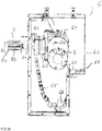
- FIG. 5 shows a block diagram for explaining the mode of operation of the treatment device or for explaining the interaction of the individual elements explained above.
- the treatment device has a controller 100.
- This controller may include, for example, a programmable controller such as a microprocessor.
- the controller 100 controls the motor 41, which rotates the shaft 2 in accordance with the controller 100.
- Information about the current angular position of the shaft 2 is given to the controller 100 by a rotary encoder 101, which is arranged in a manner not shown in the region of the shaft 2 and the controller 100 transmits the current angular position of the shaft 2.
- the controller 100 also controls the actuating unit 7 for the clutch 63, 64 and optionally the supply of the cleaning liquid or the gaseous medium via the shaft 3 to the two nozzle devices 52, 53.
- the controller 100 moves the shaft 2 via the motor 41 into a coupling position. This is the one in the FIGS. 3A and 3B shown position. In this position, the actuating element 71 of the actuating arrangement 7 can act on the second coupling element 64. If the coupling 63, 64 coupled and is to be decoupled, so the controller 100 provides energization of the electromagnet of the actuating element 71 and causes the linear drive 73 moves linearly in the direction of the second coupling element 64 to an end position at which a frictional connection between the actuating element 71 and the magnetic counterpart 69 is ensured. The controller 100 then effects a process of the linear drive 73 in the opposite direction to decouple the second coupling element 64 from the first coupling element 63.
- the second coupling element 64 In decoupled state, the second coupling element 64 is permanently held by the actuating element 71, so the electromagnet remains energized until the two coupling elements 63, 64 are coupled together again.
- the control also causes the shaft 2 to be moved to the clutch position by the motor 41.
- the controller 100 then causes the linear drive moves in the direction of the first coupling element 63, to an end position at which the first coupling element and the second coupling element are coupled together.
- the energization of the electromagnet of the actuating element 71 is then interrupted in order to be able to drive the actuating element 71 away from the second coupling element 64.
- the actuator 71 is in this case in a waiting position (in FIG. 3A shown), on which the actuating element 71 remains until the two coupling elements 63, 64 are to be decoupled again.
Landscapes
- Physical Or Chemical Processes And Apparatus (AREA)
- Cleaning By Liquid Or Steam (AREA)
- Surgical Instruments (AREA)
Description
- Ausführungsbeispiele der vorliegenden Erfindung betreffen eine Behandlungsvorrichtung für Werkteile bzw. Werkstücke.
- Speziell Metallteile bedürfen nach einem Herstellungs- oder Bearbeitungsprozess häufig einer reinigenden Behandlung, bevor die Teile verbaut oder weiterverarbeitet werden können. Auch im Rahmen einer Wiederaufbereitung von Werkteilen, wie z. B. von Motorblöcken, kann eine Reinigung erforderlich sein. Für eine solche Behandlung gibt es Behandlungsvorrichtungen mit einer Behandlungskammer, einer in der Behandlungskammer angeordneten Teileaufnahmevorrichtung und mit einer in der Behandlungskammer angeordneten Düsenvorrichtung, die zur Abgabe eines Behandlungsmediums dient. Dieses Behandlungsmedium ist ein flüssiges Medium zur reinigenden Behandlung oder ein gasförmiges Medium zur reinigenden und/oder trocknenden Behandlung. Derartige Behandlungsvorrichtungen sind beispielsweise in der
EP 0 507 294 B1 , derWO 98/45059 A1 EP 2 156 905 A1 beschrieben. - Vor dem Hintergrund, komplexe und sehr wirksame Reinigungs- oder Trocknungsverfahren mit solchen Behandlungsvorrichtungen durchführen zu wollen, besteht der Bedarf, elektrische Behandlungseinheiten drehbar in der Behandlungskammer anzuordnen. Problematisch ist es hierbei, die Stromversorgung der drehbaren Behandlungseinheit durch die Kammerwand hindurch sicherzustellen.
-
EP 2 156 905 A1 beschreibt eine Behandlungsvorrichtung für Werkstücke. InEP 0 507 294 B1 wird eine Anlage zur Reinigung und Entfettung von Werkstücken gezeigt.DE 197 14 603 C1 zeigt ein Verfahren und eine Vorrichtung zur Reinigung von Werkstücken.EP 1 346 779 A2 beschreibt eine Vorrichtung zur Aufnahme eines Werkstückträgers und zur Zuführung eines ersten und zweiten Mediums.DE 196 35 867 A1 zeigt eine Anordnung zum Betätigen einer Schaltvorrichtung eines Zahnräderwechselgetriebes und zum Ein- und Ausrücken einer Haupt-Kupplung. - Aufgabe der vorliegenden Erfindung ist es daher, eine Behandlungsvorrichtung für Werkteile zur Verfügung zu stellen, die eine elektrische Behandlungseinheit in einer Behandlungskammer aufweist, und bei der eine elektrische Versorgung der Behandlungseinheit auf einfach und relativ kostengünstig zu realisierende Weise gewährleistet ist, und ein Verfahren zum Betreiben einer solchen Behandlungsvorrichtung zur Verfügung zu stellen.
- Diese Aufgabe wird durch eine Behandlungsvorrichtung nach Anspruch 1 und ein Verfahren nach Anspruch 15 gelöst. Ausgestaltungen und Weiterbildungen sind Gegenstand der Unteransprüche.
- Ein Ausführungsbeispiel betrifft eine Behandlungsvorrichtung für Werkstücke. Die Behandlungsvorrichtung umfasst eine Behandlungskammer, eine Welle, die sich durch eine Wand der Behandlungskammer in die Behandlungskammer erstreckt und die drehbar gelagert ist, eine an der Welle befestigte elektrische Behandlungseinheit und eine Leistungsversorgung mit einer ersten Versorgungsleitung, einer elektrischen Kupplung, einer zweiten Versorgungsleitung und einer Betätigungseinheit. Die elektrische Kupplung umfasst ein außerhalb der Behandlungskammer an der Welle befestigtes erstes Kupplungselement und ein zweites Kupplungselement. Die erste Versorgungsleitung schließt die elektrische Behandlungseinheit an das erste Kupplungsteil an, und die zweite Versorgungsleitung ist an das zweite Kupplungsteil angeschlossen. Die Betätigungseinheit ist dazu ausgebildet, die Kupplung zu betätigen, um das zweite Kupplungsteil mit dem ersten Kupplungsteil in Kontakt zu bringen oder das zweite Kupplungsteil von dem ersten Kupplungsteil zu lösen.
- Ein zweites Ausführungsbeispiel betrifft ein Verfahren zum Betreiben einer solchen Behandlungsvorrichtung. Das Verfahren umfasst das Betreiben der Behandlungsvorrichtung in einem ersten Betriebszustand, in dem das zweite Kupplungsteil mit dem ersten Kupplungsteil in Kontakt ist, oder in einem zweiten Betriebszustand, in dem das zweite Kupplungsteil von dem ersten Kupplungsteil gelöst ist.
- Ausführungsbeispiele werden nachfolgend anhand von Figuren erläutert. Die Figuren sind nicht notwendigerweise maßstabsgerecht. Die Figuren dienen zur Erläuterung des Grundprinzips, so dass nur solche Merkmale, die hierfür notwendig sind, in den Figuren dargestellt sind bzw. nachfolgend im Detail erläutert sind.
- Figuren 1A-1B
- veranschaulichen ein Ausführungsbeispiel einer Behandlungsvorrichtung anhand einer perspektivischen Ansicht (
Figur 1A ) und anhand eines Ausschnitts der Behandlungsvorrichtung in einer perspektivischen Ansicht (Figur 1B ); - Figur 2
- zeigt eine perspektivische Ansicht eines Beispiels einer Behandlungseinheit.
- Figuren 3A-3C
- veranschaulichen ein Beispiel einer Leistungsversorgungsanordnung für die Behandlungseinheit;
- Figuren 4A-4B
- zeigen schematisch ein erstes Kupplungsteil und ein zweites Kupplungsteil einer elektrischen Kupplung der Leistungsversorgungsanordnung; und
- Figur 5
- zeigt ein Blockdiagramm zur Veranschaulichung der Funktionsweise der Behandlungsvorrichtung.
- Die
Figuren 1A-1B zeigen ein Ausführungsbeispiel einer Behandlungsvorrichtung für Werkstücke, die eine Behandlungskammer 1 und eine in der Behandlungskammer 1 drehbar angeordnete elektrische Behandlungseinheit 3 aufweist.Figur 1A zeigt eine perspektivische Ansicht der Behandlungskammer 1 (die in Durchsicht dargestellt ist) und weiterer, nachfolgend noch erläuterter Elemente der Behandlungsvorrichtung.Figur 1B zeigt eine perspektivische Ansicht eines Teils der Behandlungskammer 1 aus einem anderen Blickwinkel. - Bezug nehmend auf
Figur 1A umfasst die Behandlungsvorrichtung eine Welle 2, die sich durch eine Wand der Behandlungskammer 1 in die Behandlungskammer erstreckt und die drehbar gegenüber der Behandlungskammer 1 gelagert ist. Die Behandlungskammer 1 ist in dem dargestellten Ausführungsbeispiel im Wesentlichen zylindrisch, und die Welle 2 ist an einer Stirnseite der zylindrischen Behandlungskammer 1 in die Behandlungskammer 1 eingeführt. Dies ist jedoch nur ein Beispiel. Die Behandlungskammer 1 könnte auch eine andere Kammergeometrie besitzen und könnte beispielsweise kugelförmig sein. - Zur Beschickung der Behandlungskammer 1 mit zu behandelnden Werkstücken weist die Behandlungskammer 1 eine Zuführöffnung 11 auf. Diese Zuführöffnung 11 befindet sich in dem dargestellten Ausführungsbeispiel an einer Seitenwand der Behandlungskammer 1, die im Wesentlichen senkrecht zu der Stirnwand verläuft, über welche die Welle 2 in die Behandlungskammer 1 geführt ist. Ein Verschluss (Deckel), mit dem die Zuführöffnung 11 verschlossen werden kann, ist in den Figuren nicht dargestellt. Gemäß einem Ausführungsbeispiel ist der Verschluss dazu ausgebildet, die Zuführöffnung 11 wasser- und druckdicht zu verschließen, um dadurch die Behandlungskammer 1 für den Behandlungsbetrieb hermetisch abzuschließen. "Druckdicht" bedeutet in diesem Zusammenhang, dass der Verschluss in geschlossenem Zustand einem Überdruck (gegenüber dem Umgebungsdruck außerhalb der Behandlungskammer 1), beispielsweise von mehreren bar (2 bar, 5 bar oder mehr) oder auch einem Unterdruck, beispielsweise bis annähernd 0 bar, widersteht. Die Behandlungskammer 1 umfasst Dichtungen (nicht dargestellt) in dem Bereich, in dem die Welle 2 durch die Kammerwand geführt ist. Diese Dichtungen sind entsprechend des Verschlusses dazu ausgebildet, die Behandlungskammer 1 wasser- und druckdicht zu verschließen.
- Bezug nehmend auf
Figur 1A ist im Inneren der Behandlungskammer 1 eine Teileaufnahme 12 angeordnet, die dazu dient, zu behandelnde Teile während des Behandlungsprozesses zu halten. Bei einem Ausführungsbeispiel ist die Teileaufnahme 12 dazu ausgebildet, Körbe aufzunehmen, in denen zu behandelnde Werkstücke lose (als Schüttgut) liegen. Gemäß einem weiteren Ausführungsbeispiel ist die Teileaufnahme 12 dazu ausgebildet, einzelne große Werkstücke, wie beispielsweise Motorblöcke, aufzunehmen. Die Teileaufnahme 12 kann Rollen 13 aufweisen, die ein "Einfahren" und "Ausfahren" der Werkstückkörbe bzw. der Werkstücke über die Zuführöffnung 11 in die Behandlungskammer 1 erleichtern. - Gemäß einem Ausführungsbeispiel ist die Teileaufnahme 12 drehbar gegenüber der Behandlungskammer 1 gelagert. In diesem Fall umfasst die Behandlungsvorrichtung 1 eine weitere Welle 13 (vergleiche
Figur 1B ). Diese weitere Welle 13 kann an einer Kammerwand in die Behandlungskammer 1 geführt sein, die der Kammerwand gegenüberliegt, an der die Welle 2 in die Behandlungskammer 1 geführt ist. Diese Welle 13 kann motorisch angetrieben werden. Eine solche drehbar angeordnete Teileaufnahme 12 ist grundsätzlich bekannt, so dass auf die Erläuterung weiterer Details dieser Teileaufnahme, wie beispielsweise der zugehörigen Antriebsvorrichtung, hier verzichtet werden kann. - Bezug nehmend auf
Figur 1A wird die Welle 2 beispielsweise von einer elektrischen Antriebsvorrichtung 4 angetrieben. Diese Antriebsvorrichtung 4 umfasst beispielsweise einen Elektromotor 41 und ein Getriebe, von dem inFigur 1A ein Zahnrad 42 dargestellt ist. Die Antriebsvorrichtung greift beispielsweise an einem an der Welle 2 befestigten und kraftschlüssig mit der Welle 2 verbundenen Zahnrad 21 an. Die Antriebsanordnung 4 kann außerdem eine Montageplatte 43 umfassen, an der der Motor 41 befestigt ist. Gemäß einem Ausführungsbeispiel ist die Welle 2 durch eine Öffnung (nicht dargestellt) der Montageplatte 43 geführt. Die Montageplatte 43 kann in nicht näher dargestellter Weise an einem Gehäuse (nicht dargestellt) der Behandlungsvorrichtung befestigt sein. Dieses Gehäuse umgibt alle der in derFigur 1A dargestellten Komponenten der Behandlungsvorrichtung und trägt diese. - Bezug nehmend auf
Figur 1A ist an der Welle 2 im Inneren der Behandlungskammer 1 eine elektrische Behandlungseinheit 3 befestigt. Die elektrische Behandlungseinheit 3 umfasst beispielsweise einen Ultraschallgeber, der dazu ausgebildet ist, in eingeschaltetem Zustand Ultraschallwellen in einem ihn umgebenden Medium, wie zum Beispiel einer Behandlungsflüssigkeit, zu erzeugen. Bei dem inFigur 1A dargestellten Ausführungsbeispiel umfasst die elektrische Behandlungseinheit 3 zwei stabförmige und im Wesentlichen parallel zueinander angeordnete Ultraschallgeber 3A, 3B. -
Figur 2 zeigt ein weiteres Ausführungsbeispiel einer Behandlungsvorrichtung, wobei inFigur 2 die Behandlungskammer 1 nicht dargestellt ist. Bei dem in Figur 2 dargestellten Ausführungsbeispiel umfasst die elektrische Behandlungseinheit 3 vier solcher stabförmiger Ultraschallgeber 3A-3D. Das Vorsehen mehrerer Ultraschallgeber ist jedoch nur ein Beispiel. Bei einem weiteren Ausführungsbeispiel ist vorgesehen, nur einen der in denFiguren 1A und2 dargestellten Ultraschallgeber zu sehen. Außerdem ist das Vorsehen stabförmiger Ultraschallgeber nur ein Beispiel. Auch andere Arten von Ultraschallgebern könnten verwendet werden. - Bei den in den
Figuren 1A und2 dargestellten Ausführungsbeispielen verlaufen die stabförmigen Ultraschallgeber 3A-3B bzw. 3A-3D im Wesentlichen parallel zu der Welle 2, an der sie befestigt sind. Zur Befestigung der Ultraschallgeber 3A-3D an der Welle 2 sind in dem dargestellten Beispiel Verbindungselemente (31AB, 31CD inFigur 2 ) vorgesehen, die sich im Wesentlichen in radialer Richtung von der Welle 2 weg erstrecken. Diese Verbindungselemente 31AB, 31CD sind an der Welle 2 zugewandten Enden an der Welle 2 befestigt, beispielsweise durch Schraubverbindungen. An von der Welle 2 abgewandten Enden der Verbindungselemente 31AB, 31CD sind die Ultraschallgeber 3A-3D befestigt. - Eine elektrische Behandlungseinheit mit Ultraschallgebern, wie die in den
Figuren 1A und2 dargestellte elektrische Behandlungseinheit 3, ist nur ein Beispiel für eine elektrische Behandlungseinheit. Anstelle einer elektrischen Behandlungseinheit mit Ultraschallgebern oder zusätzlich zu einer solchen elektrischen Behandlungseinheit mit Ultraschallgebern könnten auch andere Arten von elektrischen Behandlungseinheiten im Inneren der Behandlungskammer 1 an der Welle 2 befestigt sein. Unter einer "elektrischen Behandlungseinheit" ist eine elektrische Behandlungseinheit zu verstehen, für deren Betrieb elektrische Energie (Strom) benötigt wird. Solch eine elektrische Behandlungseinheit ist beispielsweise auch eine Behandlungseinheit mit einem elektrischen Heizelement oder mit einer elektrisch verstellbaren Düse. Bei einem elektrischen Heizelement wird der Strom dazu verwendet, Wärme zu erzeugen, die an die Umgebung in der Behandlungskammer abgegeben wird. Bei einer elektrisch verstellbaren Düse wird der Strom dazu verwendet, die Düse zu verstellen bzw. zu schwenken oder ähnliches. Die Düse ist beispielsweise eine Düse für Reinigungsflüssigkeit oder für ein gasförmiges Medium, wie beispielsweise Luft. Eine solche Düse kann einen beliebig gearteten, durch elektrischen Strom versorgten Antrieb besitzen, wie beispielsweise einen Antrieb mit einem Piezoelement, einem Getriebe, einer Hydraulik oder ähnlichem. - Um die im Inneren der Behandlungskammer 1 angeordnete elektrische Behandlungseinheit 3 mit elektrischer Energie (Strom) zu versorgen, umfasst die Behandlungsvorrichtung eine Leistungsversorgungsanordnung. Die
Figuren 3A-3C veranschaulichen ein Ausführungsbeispiel einer solchen Leistungsversorgungsanordnung 6. Teile dieser Leistungsversorgungsanordnung 6 sind auch in denFiguren 1A und2 dargestellt. - Die Leistungsversorgungsanordnung umfasst eine elektrische Kupplung mit einem außerhalb der Behandlungskammer 1 an der Welle 2 befestigten ersten Kupplungselement 63 und einem zweiten Kupplungselement 64, wenigstens eine erste Versorgungsleitung 61, wenigstens eine zweite Versorgungsleitung 62 und eine Betätigungseinheit 7 für die elektrische Kupplung 63, 64. Die wenigstens eine erste Versorgungsleitung 61 schließt die elektrische Behandlungseinheit 3 an das erste Kupplungselement 63 an. Dies ist beispielsweise in
Figur 2 dargestellt.Figur 2 zeigt zwei erste Versorgungsleitungen, nämlich je eine erste Versorgungsleitung für einen der Ultraschallgeber 3A, 3B. Erste Versorgungsleitungen für die Ultraschallgeber 3C, 3D sind außerhalb der Darstellung gemäßFigur 2 . Bezug nehmend aufFigur 2 ist die wenigstens eine erste Versorgungsleitung 61 wenigstens abschnittsweise innerhalb der Welle 2 geführt. Die Welle 2 weist hierfür einen axial verlaufenden Kabelkanal 22 auf, der inFigur 2 aufgeschnitten dargestellt ist. Dieser Kabelkanal 22, der in dem Beispiel zwei erste Versorgungsleitungen aufnimmt, verläuft von außerhalb der Behandlungskammer (die inFigur 2 nicht dargestellt ist) innerhalb der Welle 2 bis in die Behandlungskammer. Die erste Versorgungsleitung 61 tritt innerhalb der Behandlungskammer 1 aus dem Kabelkanal 22 der Welle 2 aus und ist von dort zu der an der Welle 2 befestigten Behandlungseinheit 3 geführt. Bei dem inFigur 2 dargestellten Ausführungsbeispiel verläuft die dargestellte wenigstens eine erste Versorgungsleitung 61 innerhalb des Verbindungsteils 31AB, das an der Welle 2 befestigt ist, zu dem zugehörigen Ultraschallgeber 3A, 3B. - Außerhalb der Welle 2 verläuft die wenigsten eine erste Versorgungsleitung 61 aus dem Kabelkanal 22 zu dem ersten Kupplungsteil 63, das außerhalb der Behandlungskammer 1 an der Welle 1 befestigt ist. Der Verlauf der ersten Versorgungsleitung 61 von dem Kabelkanal der Welle 2 zu dem ersten Kupplungselement 63 ist in den
Figuren 3A und3B dargestellt.Figur 3C zeigt die Leistungsversorgungsanordnung ohne die ersten und zweiten Versorgungsleitungen 61, 62. - Die Leistungsversorgungsanordnung 6 kann ein Gehäuse 66 aufweisen, in dem das erste Kupplungselement 63, das zweite Kupplungselement 64, der zwischen dem ersten Kupplungselement 63 und Kabelkanal angeordnete Abschnitt der ersten Versorgungsleitung 61 und die zweite Versorgungsleitung 62 angeordnet sind. Dieses Gehäuse 66 schützt die zuvor genannten Komponenten der Leistungsversorgungsanordnung 6 während des Betriebs vor Verschmutzung und Feuchtigkeit. Von diesem Gehäuse 66 sind in den
Figuren 3A-3C eine Rückwand und Seitenwände dargestellt. Eine vordere Abdeckung ist in der Figur nicht gezeigt. Die Rückwand weist eine Aussparung auf, durch welche die Welle 2 verläuft. Die nicht dargestellte Abdeckung des Gehäuses 66 weist eine entsprechende Aussparung auf. Gemäß einem Ausführungsbeispiel ist im Bereich der Aussparungen der Rückwand und der Abdeckung eine Dichtung vorgesehen, die das Eindringen von Feuchtigkeit und Schmutz in das Gehäuse 66 im Bereich der Welle 2 verhindert. Bezug nehmend aufFigur 3C kann das Gehäuse 66 an der zuvor erläuterten Montageplatte 43 (siehe auchFigur 1A ) befestigt sein. - Die zweite Versorgungsleitung 62 ist an einem Kabeleinlass 67 in das Gehäuse 66 eingeführt. Die zweite Versorgungsleitung 62 ist an eine Leistungsquelle (nicht dargestellt) angeschlossen. Hierzu kann sich die zweite Versorgungsleitung 62 außerhalb des Gehäuses 66 bis zu der Leistungsquelle erstrecken. Alternativ besteht die Möglichkeit, die zweite Versorgungsleitung 62 über eine weitere Versorgungsleitung (nicht dargestellt) an die Leistungsquelle anzuschließen. Die Leistungsquelle ist eine zur elektrischen Versorgung der Behandlungseinheit 3 geeignete Leistungsquelle. Die Art der Leistungsquelle ist also abhängig von der Art der elektrischen Behandlungseinheit 3. Bei einer elektrischen Behandlungseinheit 3 mit Ultraschallgebern (wie in den
Figuren 1A-1B und2 dargestellt ist), ist die Leistungsquelle ein Hochfrequenzgenerator, der dazu ausgebildet ist, ein zur Ansteuerung der Ultraschallgeber 3A-3D geeignetes Hochfrequenzsignal zu erzeugen. Dieses Hochfrequenzsignal versorgt die elektrische Behandlungseinheit 3 über die wenigstens eine zweite Versorgungsleitung 62, die Kupplung 63, 64 und die wenigstens eine erste Versorgungsleitung 61, wenn das erste und das zweite Kupplungselement 63, 64 miteinander gekoppelt sind. - In gekoppeltem Zustand, also wenn das erste Kupplungselement 63 mit dem zweiten Kupplungselement 64 der Kupplung gekoppelt ist, stellt die Kupplung eine elektrisch leitende Verbindung zwischen der ersten Versorgungsleitung 61 und der zweiten Versorgungsleitung 62 zur Verfügung. Die Kupplung mit den beiden Kupplungselementen 63, 64 kann eine herkömmliche elektrische Kupplung sein, die auf den jeweiligen Anwendungszweck abgestimmt ist, die also geeignet ist, die beiden Versorgungsleitungen 61, 62 zur Versorgung der Behandlungseinheit 3 elektrisch leitend miteinander zu verbinden.
-
Figur 3A zeigt die Kupplungselemente 63, 64 in gekoppeltem (elektrisch miteinander verbundenem) Zustand undFigur 3B zeigt die beiden Kupplungselemente 63, 64 in entkoppeltem (elektrisch voneinander getrenntem) Zustand. - Zum Koppeln bzw. Entkoppeln der beiden Kupplungselemente 63, 64 weist die Behandlungsvorrichtung eine Betätigungseinheit 7 auf. Diese Betätigungseinheit 7 umfasst ein Betätigungselement 71, das kraftschlüssig mit dem zweiten Kupplungselement 64 in Verbindung gebracht werden kann, um das zweite Kupplungselement 64 mit dem ersten Kupplungselement 63 zu verbinden oder um das zweite Kupplungselement 64 von dem ersten Kupplungselement 63 zu lösen.
- Gemäß einem Ausführungsbeispiel erfolgt das Herstellen der kraftschlüssigen Verbindung zwischen dem Betätigungselement 71 und dem zweiten Kupplungselement 64 durch Einsatz magnetischer Kräfte. Hierzu ist vorgesehen, dass das Betätigungselement 71 oder das zweite Kupplungselement 64 einen Elektromagnet aufweisen, und dass die jeweils andere dieser beiden Komponenten ein magnetisches Gegenstück aufweist, an dem der Elektromagnet angreifen kann. Bei einem Ausführungsbeispiel umfasst das Betätigungselement 71 einen Elektromagnet und das zweite Kupplungselement 64 umfasst an einer dem ersten Kupplungselement 63 abgewandten Seite ein magnetisches Gegenstück 69, an dem das Betätigungselement 71 mit dem Elektromagnet angreifen kann. Das magnetische Gegenstück 69 umfasst ein magnetisches Material, wie beispielsweise ein magnetisches Metall. Die Ansteuerung des Elektromagnets in dem Betätigungselement 71 erfolgt über eine Steuerleitung 72, die in den
Figuren 3A-3C schematisch dargestellt ist. Über diese Steuerleitung 72 wird der Elektromagnet entweder aktiviert oder deaktiviert. In aktiviertem Zustand kann der Elektromagnet kraftschlüssig mit dem magnetischen Gegenstück 69 an dem zweiten Kupplungselement 64 in Verbindung gebracht werden. - Um das zweite Kupplungselement 64 in Richtung des ersten Kupplungselements 63 bewegen zu können (um diese zu koppeln) oder um das zweite Kupplungselement 64 von dem ersten Kupplungselement 64 abziehen zu können (um diese zu trennen) umfasst die Betätigungseinheit 7 einen Linearantrieb 73, an dem das Betätigungselement 71 befestigt ist. Der Linearantrieb 73 ist dazu ausgebildet, das Betätigungselement 71 linear zu verfahren, um das Betätigungselement 71 mit dem zweiten Kupplungselement 64 in Kontakt bringen zu können und so das zweite Kupplungselement 64 zu betätigen, das heißt von dem ersten Kupplungselement 63 abzuziehen oder mit dem zweiten Kupplungselement 63 in Kontakt zu bringen. Der Linearantrieb 73 umfasst beispielsweise einen Pneumatikzylinder oder einen elektrischen Linearmotor. Die Versorgung bzw. Ansteuerung des Linearantriebs 73 erfolgt über eine weitere Zuführleitung 74.
- Bezug nehmend auf
Figur 3A bildet die wenigstens eine zweite Versorgungsleitung 62 innerhalb des Gehäuses 66 eine Kabelschlaufe, die dann, wenn das erste und das zweite Kupplungselement 63, 64 miteinander gekoppelt sind, ein Drehen der Welle 2 ermöglicht, ohne dass die zweite Versorgungsleitung 62 abreißt oder anderweitig beschädigt wird. Die zweite Versorgungsleitung 62 kann innerhalb des Gehäuses 66 in einer Kabelschleppe 65 geführt sein. In welchem Umfang sich die Welle 2 bei gekoppelter Kupplung 63, 64 drehen kann, ohne dass sich die Kupplung 63, 64 selbst löst oder die zweite Versorgungsleitung 62 abreißt, ist abhängig von der Länge der zweiten Versorgungsleitung 62 innerhalb des Gehäuses 66, also abhängig von der Leitungsreserve der zweiten Versorgungsleitung 62. Gemäß einem Ausführungsbeispiel ist die zweite Versorgungsleitung 62 so dimensioniert, dass die Welle 2 bei gekoppelter Kupplung 63, 64 einen Drehbereich von maximal 180°, maximal 270°, maximal 360°, oder sogar maximal 720° besitzt. Der "Drehbereich" bezeichnet einen Winkelbereich zwischen einem ersten Endpunkt und einem zweiten Endpunkt der Welle. Der "erste Endpunkt" bezeichnet eine Winkelposition, bis zu welcher die Welle 2 bei gekoppelter Kupplung 63, 64 in einer ersten Richtung gedreht werden kann, ohne dass die Gefahr einer Beschädigung der Leistungsversorgungsanordnung besteht, und "der zweite Endpunkt" bezeichnet eine Winkelposition der Welle 2, bis zu welcher die Welle 2 in einer zu der ersten Drehrichtung entgegengesetzten zweiten Drehrichtung gedreht werden kann, ohne dass die Gefahr einer Beschädigung der Leistungsversorgungsanordnung besteht. - Die
Figuren 3A und3B zeigen die Welle 2 in einer Winkelposition, bei der die Betätigungseinheit 7 die beiden Kupplungselemente 63, 64 miteinander koppeln oder voneinander entkoppeln kann. Ausgehend von dieser Winkelposition kann bei dem dargestellten Beispiel die Welle 2 in einer ersten Richtung, die in dem Beispiel dem Uhrzeigersinn entspricht, ein Stück gedreht werden, ohne dass die Gefahr besteht, die zweite Versorgungsleitung 62 abzureißen. Die Kabelschlaufe der zweiten Versorgungsleitung 62 unterhalb der Welle 2 verkürzt sich dann und die zweite Versorgungsleitung wickelt sich um die Welle 2. Ein optionales Spannelement 68, das in dem Beispiel in vertikaler Richtung verschiebbar ist, hält die zweite Versorgungsleitung 62 in diesem Fall gespannt bzw. hält die Schlaufe aufrecht. In dem dargestellten Beispiel kann die Welle 2 im Uhrzeigersinn um bis zu 360° gedreht werden. In der entgegengesetzten Richtung (also bei dem Beispiel entgegen dem Uhrzeigersinn) kann die Welle 2 in dem Beispiel ebenfalls um 360° gedreht werden, ohne dass die Gefahr besteht, die Versorgungsleitung 62 abzureißen. In diesem Fall kann die Welle also in beide Richtungen um 360°, d.h. um +/- 360° gedreht werden. Der Drehbereich beträgt also 720°, da die beiden Endpunkte 720° auseinander liegen. - Die weitere Versorgungsleitung 62 ist in dem dargestellten Beispiel an einer Seitenwand in das Gehäuse 66 eingeführt. Die Betätigungseinheit 7 befindet sich an einer der ersten Seitenwand gegenüberliegenden Seitenwand des Gehäuses 66. Dies ist allerdings nur ein Beispiel. Die Einführung der zweiten Versorgungsleitung 62 in das Gehäuse 6 kann an einer beliebigen Stelle erfolgen. Maßgeblich für den zulässigen Drehbereich der Welle 2 bei gekoppelter Kupplung ist die innerhalb des Gehäuses 66 vorhandene Kabelreserve der zweiten Versorgungsleitung 62, also die Länge der zweiten Versorgungsleitung 62 innerhalb des Gehäuses 66. Je länger diese Versorgungsleitung 62 ist, umso größer ist der Drehbereich.
- Die Kupplung mit den beiden Kupplungselementen 63, 64 kann eine herkömmliche elektrische Kupplung sein, die eine elektrisch leitende Verbindung zwischen den beiden Versorgungsleitungen 61, 62 gewährleistet. So kann eines der beiden Kupplungselemente 63, 64 beispielsweise Kontaktstifte aufweisen, die in gekoppeltem Zustand in korrespondierende Buchsen des anderen Kupplungselements stecken. Gemäß einem weiteren Beispiel weisen beide Kupplungselemente 63, 64 Kontakte auf, die als Federkontakte ausgebildet sind.
- Eine mechanische Verbindung zwischen den beiden Kupplungselementen 63, 64, die ein selbsttätiges Lösen der Kupplung verhindert, kann auf unterschiedliche Weise gewährleistet werden, wie beispielsweise durch Klemmelemente, Federelemente, oder ähnliches. Gemäß einem weiteren Ausführungsbeispiel ist vorgesehen, dass eines der beiden Kupplungselemente 63, 64 an einer dem jeweils anderen Kupplungselement zugewandten Kontaktfläche einen Permanentmagnet aufweist, der in gekoppeltem Zustand der Kupplungselemente 63, 64 kraftschlüssig mit einem magnetischen Gegenstück des jeweils anderen Kupplungselements in Verbindung steht, um die beiden Kupplungselemente 63, 64 in gekoppeltem Zustand zusammen zu halten.
- Die
Figuren 4A und 4B zeigen jeweils Draufsichten auf eine Kontaktfläche des ersten Kupplungselements 63 (Figur 4A ) und des zweiten Kupplungselements 64 (Figur 4B ) gemäß einem Beispiel. In dem dargestellten Ausführungsbeispiel umfasst jedes der Kupplungselemente 63, 64 vier Kontakte 631-634 bzw. 641-644. Jedes Kontaktelement eines Kupplungselements besitzt ein korrespondierendes Kontaktelement an dem jeweils anderen Kupplungselement und ist elektrisch mit diesem in Kontakt, wenn die beiden Kupplungselemente 63, 64 gekoppelt sind. Die einzelnen Kontaktelemente 631-634 bzw. 641-644 können als herkömmliche elektrische Kontakte ausgebildet sein, wie beispielsweise als Federkontakte. Es besteht auch die Möglichkeit, einen der korrespondierenden Kontakte als Kontaktstift und den anderen der korrespondierenden Kontakte als Kontaktbuchse zu realisieren. Die Anzahl der Kontaktelemente ist beliebig und abhängig von dem jeweiligen Zweck bzw. der Anzahl der zu versorgenden elektrischen Verbraucher, und damit nicht auf vier beschränkt. - Wenigstens eines der beiden Kupplungselemente 63, 64 besitzt an der Kontaktfläche einen Permanentmagnet, der in gekoppeltem Zustand an einem magnetischen Gegenstück des jeweiligen anderen Kupplungselements 63, 64 angreift. Der Permanentmagnet und das magnetischen Gegenstück sind in den
Figuren 4A und 4B mit den Bezugszeichen 635, 645 bezeichnet. Diese sind in dem dargestellten Ausführungsbeispiel ringförmig um die Kontakte 631-634 bzw. 641-644 angeordnet. Dies ist jedoch nur ein Beispiel. Eine beliebige andere Geometrie ist ebenfalls möglich. - Bei dem Ausführungsbeispiel ist vorgesehen, dass ein Permanentmagnet vorhanden ist. Dieser Permanentmagnet entspricht entweder in
Figur 4A dem mit dem Bezugszeichen 635 bezeichneten Element oder inFigur 4B dem mit dem Bezugszeichen 645 bezeichneten Element. Das Gegenstück besteht dann aus einem magnetischen Material, wie beispielsweise einem magnetischen Metall. Gemäß einem anderen Ausführungsbeispiel ist vorgesehen, an jedem der beiden Kupplungselemente 63, 64 einen Permanentmagnet vorzusehen, wobei diese Magnete derart an den Kontaktflächen angeordnet sind, dass die Permanentmagnete an den Kontaktflächen, also an den Flächen, die bei gekoppelter Kupplung miteinander in Kontakt stehen, entgegengesetzte magnetische Pole besitzen, also dass sich die Permanentmagnete gegenseitig anziehen. - Der Elektromagnet des Betätigungselements 7 und das magnetische Gegenstück 69 an dem zweiten Kupplungselement 64 sind so dimensioniert, dass das Betätigungselement 7 in der Lage ist, das zweite Kupplungselement 64 gegen die von dem wenigstens einen Permanentmagnet und dem magnetischen Gegenstück der Kupplungselemente 63, 64 hervorgerufene Magnetkraft voneinander zu lösen.
- Bei der erläuterten Behandlungsvorrichtung ist der Drehbereich der Welle 2 bei gekoppelter Kupplung 63, 64 in der zuvor erläuterten Weise eingeschränkt. Die Welle 2 kann insbesondere nicht mehrmals hintereinander in einer Richtung vollständig gedreht werden. Innerhalb des möglichen Drehbereichs ist allerdings ein beliebiges Schwenken, das heißt ein abwechselndes Drehen der Welle in einer Drehrichtung und der entgegengesetzten Drehrichtung beliebig möglich. Insbesondere bei einer Behandlungsvorrichtung mit einem Drehbereich von 360° kann die Behandlungseinheit 3 an einer beliebigen Winkelposition innerhalb der Behandlungskammer 1 positioniert werden bzw. innerhalb des Drehbereichs beliebig hin- und hergeschwenkt werden. Bei entkoppelter Kupplung 63, 64 besteht keine Einschränkung hinsichtlich einer Drehbewegung der Welle 2. Das heißt, die Welle kann in diesem Fall mehrmals aufeinander folgend in einer Richtung vollständig gedreht werden.
- Bei einem Beispiel ist vorgesehen, dass an der Welle 2 zusätzlich zu der elektrischen Behandlungseinheit 3 ein erstes Düsenrohr 51 (vergleiche
Figur 1A ) befestigt ist. Dieses Düsenrohr 51 umfasst mehrere entlang des Düsenrohrs angeordnete Düsen 52, über welche Reinigungsflüssigkeit in der Behandlungskammer 1 in Richtung der Teileaufnahme 12, und damit in Richtung der zu reinigenden Werkteile abgegeben werden kann. Die Zuführung von Reinigungsflüssigkeit zu dem Düsenrohr 51 erfolgt von außerhalb der Behandlungskammer 1 über einen Flüssigkeitskanal 23. Dieser Flüssigkeitskanal 23 verläuft in dem dargestellten Ausführungsbeispiel zentral innerhalb der Welle 2. Innerhalb der Behandlungskammer 1 mündet eine radial in der Welle 2 verlaufende Bohrung in diesen Flüssigkeitskanal 23. Das Düsenrohr 51 ist derart im Bereich dieser radialen Bohrung an der Welle 2 befestigt, dass Reinigungsflüssigkeit über den Flüssigkeitskanal 23 und die radiale Bohrung in das Düsenrohr 51 gelangen kann. Die Zuführung von Reinigungsflüssigkeit in den Flüssigkeitskanal 23 der Welle 2 erfolgt beispielsweise über ein Zuführrohr (in den Figuren nicht dargestellt), das außerhalb der Behandlungskammer angeordnet ist und gegenüber dem die Welle 2 drehbar gelagert ist. Über herkömmliche Dichtungen kann sichergestellt werden, dass in dem Bereich, in dem das Zuführrohr an die Welle 2 gekoppelt ist, keine Flüssigkeit austritt. - Bezug nehmend auf die
Figuren 1A und2 kann die Behandlungsvorrichtung ein weiteres, an der Welle 2 befestigtes Düsenrohr 53 umfassen. Dieses weitere Düsenrohr 53 dient beispielsweise zum Einbringen eines gasförmigen Mediums, wie beispielsweise Luft, in die Behandlungskammer 1. Das gasförmige Medium kann beispielsweise zum Trocknen der zuvor mit Reinigungsflüssigkeit gereinigten Werkteile verwendet werden. Zum Einbringen dieses gasförmigen Mediums in das weitere Düsenrohr 53 umfasst die Welle 2 einen weiteren Zuführkanal, der innerhalb der Welle in deren Längsrichtung von außerhalb der Behandlungskammer bis in die Behandlungskammer verläuft. Dieser weitere Zuführkanal mündet innerhalb der Behandlungskammer 1 in das weitere Düsenrohr 53 und ist außerhalb der Behandlungskammer über eine senkrecht zur Längsrichtung verlaufende Bohrung 24 zugänglich. Diese Bohrung 24 ist beispielsweise in denFiguren 3A und3B dargestellt. Zum Einbringen des gasförmigen Mediums in den weiteren Zuführkanal der Welle 2, und damit in das weitere Düsenrohr 53 kann ein ringförmiger Kanal (nicht dargestellt) vorgesehen sein, der die Welle 2 in Umfangsrichtung im Bereich der Bohrung 24 umgibt. Dieser ringförmige Kanal mündet in jeder Winkelstellung der Welle 2 in die Bohrung 24. Ein derartiger Ringkanal zur Zuführung eines gasförmigen Mediums in eine Welle einer Behandlungsvorrichtung ist bekannt, so dass auf weitere Ausführungen diesbezüglich verzichtet werden kann. - Bei entkoppelter Kupplung 63, 64 kann die Behandlungsvorrichtung wie eine herkömmliche Behandlungsvorrichtung betrieben werden. Das heißt, in einem Behandlungsschritt kann Reinigungsflüssigkeit über das erste Düsenrohr 52 auf Werkteile in der Behandlungskammer 1 abgegeben werden, wobei das erste Düsenrohr 52 in der Welle 2 in der Behandlungskammer 1 beliebig gedreht oder geschwenkt werden kann. In einem anderen Behandlungsschritt kann ein gasförmiges Medium über das zweite Düsenrohr 53 in der Behandlungskammer an die Werkteile abgegeben werden. Dies kann zum Trocknen der Werkteile erfolgen. Es ist jedoch auch möglich, ein Flüssigkeitsbad in dem Behandlungsbehälter 1 zu erzeugen und das gasförmige Medium in dieses Flüssigkeitsbad abzugeben, wodurch das Flüssigkeitsbad verwirbelt wird, was zu einer hohen Reinigungsaktivität führen kann. Das Flüssigkeitsbad kann durch Einbringen von Reinigungsflüssigkeit über das erste Düsenrohr 52 erfolgen. Bei einem weiteren Ausführungsbeispiel ist vorgesehen, dass die Behandlungskammer 1 einen zusätzlichen Flüssigkeitseinlass (nicht dargestellt) besitzt. Selbstverständlich besitzt die Behandlungskammer 1 auch einen Flüssigkeitsauslass an einem unteren Ende, um zuvor in die Behandlungskammer 1 eingebrachte Reinigungsflüssigkeit wieder abführen zu können.
- Wenn die Kupplungselemente 63, 64 aneinander gekoppelt sind, ist der Drehbereich der Welle 2 in zuvor erläuterter Weise eingeschränkt. Eine elektrische Behandlungseinheit 3 mit einem Ultraschallgeber (wie in den
Figuren 1A und2 dargestellt) kann beispielsweise verwendet werden, nach Herstellen eines Flüssigkeitsbades in der Behandlungskammer 1 Ultraschallwellen an das Flüssigkeitsbad abzugeben, um auf diese Weise die in dem Flüssigkeitsbad befindlichen Werkteile zu reinigen. Die Behandlungseinheit 3 kann dabei innerhalb der Behandlungskammer 1 in der zuvor erläuterten Weise durch abwechselndes Drehen der Welle in einer Richtung bzw. der entgegengesetzten anderen Richtung geschwenkt werden. - Das Drehen der Welle 3 erfolgt durch den zuvor erläuterten Motor 41 gesteuert durch eine Steuerung. Diese Steuerung ist in den Figuren nicht dargestellt. Figur 5 zeigt ein Blockschaltbild zur Erläuterung der Funktionsweise der Behandlungsvorrichtung bzw. zur Erläuterung des Zusammenwirkens der einzelnen zuvor erläuterten Elemente. Bezug nehmend auf
Figur 5 weist die Behandlungsvorrichtung eine Steuerung 100 auf. Diese Steuerung kann beispielsweise eine programmierbare Steuerung, wie beispielsweise einen Mikroprozessor, umfassen. Die Steuerung 100 steuert den Motor 41, der die Welle 2 nach Maßgabe der Steuerung 100 dreht. Eine Information über die aktuelle Winkelstellung der Welle 2 erhält die Steuerung 100 von einem Drehgeber 101, der in nicht näher dargestellter Weise im Bereich der Welle 2 angeordnet ist und der der Steuerung 100 die aktuelle Winkelstellung der Welle 2 übermittelt. Die Steuerung 100 steuert außerdem die Betätigungseinheit 7 für die Kupplung 63, 64 und gegebenenfalls die Zuführung der Reinigungsflüssigkeit bzw. des gasförmigen Mediums über die Welle 3 zu den beiden Düsenvorrichtungen 52, 53. - Zum Koppeln oder Entkoppeln der beiden Kupplungselemente 63, 64 bewegt die Steuerung 100 über den Motor 41 die Welle 2 in eine Kopplungsposition. Dies ist die in den
Figuren 3A und3B dargestellte Position. In dieser Position kann das Betätigungselement 71 der Betätigungsanordnung 7 an dem zweiten Kupplungselement 64 angreifen. Ist die Kupplung 63, 64 gekoppelt und soll entkoppelt werden, so sorgt die Steuerung 100 für eine Bestromung des Elektromagnets des Betätigungselements 71 und bewirkt, dass der Linearantrieb 73 linear in Richtung des zweiten Kupplungselements 64 bis zu einer Endposition verfährt, an der eine kraftschlüssige Verbindung zwischen dem Betätigungselement 71 und dem magnetischen Gegenstück 69 sichergestellt ist. Die Steuerung 100 bewirkt anschließend ein Verfahren des Linearantriebs 73 in der entgegengesetzten Richtung, um das zweite Kupplungselement 64 von dem ersten Kupplungselement 63 zu entkoppeln. - In entkoppeltem Zustand wird das zweite Kupplungselement 64 permanent von dem Betätigungselement 71 gehalten, der Elektromagnet bleibt also bestromt, bis die beiden Kupplungselemente 63, 64 wieder miteinander gekoppelt werden.
- Zum Koppeln des zweiten Kupplungselements 64 und des ersten Kupplungselements 63 bewirkt die Steuerung ebenfalls, dass die Welle 2 durch den Motor 41 in die Kupplungsposition bewegt wird. Die Steuerung 100 bewirkt dann, dass der Linearantrieb in Richtung des ersten Kupplungselements 63 verfährt, und zwar bis zu einer Endposition, an der das erste Kupplungselement und das zweite Kupplungselement miteinander gekoppelt sind. Die Bestromung des Elektromagnets des Betätigungselements 71 wird dann unterbrochen, um das Betätigungselement 71 von dem zweiten Kupplungselement 64 wegfahren zu können. Dieser erfolgt ebenfalls gesteuert durch die Steuerung 100. Das Betätigungselement 71 wird hierbei in eine Warteposition (in
Figur 3A dargestellt) verfahren, an welcher das Betätigungselement 71 verbleibt, bis die beiden Kupplungselemente 63, 64 wieder entkoppelt werden sollen.
Claims (17)
- Behandlungsvorrichtung für Werkstücke, die aufweist:eine Behandlungskammer (1);eine Welle (2), die sich durch eine Wand der Behandlungskammer (1) in die Behandlungskammer (1) erstreckt und die drehbar gelagert ist;eine an der Welle (2) befestigte elektrische Behandlungseinheit (3);eine Leistungsversorgungsanordnung (6) mit einer ersten Versorgungsleitung (61),dadurch gekennzeichnet, dass die Leistungsversorgungsanordnung (6) mit einer elektrischen Kupplung (63, 64), einer zweiten Versorgungsleitung (62) und einer Betätigungseinheit (7) ausgestattet ist,wobeidie elektrische Kupplung (63, 64) ein außerhalb der Behandlungskammer (1) an der Welle (2) befestigtes erstes Kupplungselement (63) und ein zweites Kupplungselement (64) aufweist,die erste Versorgungsleitung (61) die elektrische Behandlungseinheit (3) an das erste Kupplungselement (63) anschließt,die zweite Versorgungsleitung (62) an das zweite Kupplungselement (64) angeschlossen ist, unddie Betätigungseinheit (7) dazu ausgebildet ist, die Kupplung (63, 64) zu betätigen, um das zweite Kupplungselement (64) mit dem ersten Kupplungselement (63) in Kontakt zu bringen oder das zweite Kupplungselement (64) von dem ersten Kupplungselement (63) zu lösen.
- Behandlungsvorrichtung nach Anspruch 1, bei der die elektrische Behandlungseinheit (3) wenigstens eines der folgenden aufweist:einen Ultraschallgeber (3A-3D),ein elektrisches Heizelement,eine elektrisch verstellbare Düse.
- Behandlungsvorrichtung nach Anspruch 1 oder 2, bei der die erste Versorgungsleitung (61) wenigstens abschnittsweise innerhalb der Welle (2) verläuft.
- Behandlungsvorrichtung nach einem der vorangehenden Ansprüche,
bei dem das erste Kupplungselement (63) und das zweite Kupplungselement (64) jeweils eine Kontaktfläche aufweisen, die einander zugewandt sind, wenn das zweite Kupplungselement (64) mit dem ersten Kupplungselement (63) in Kontakt gebracht ist,
wobei eines von dem ersten Kupplungselement (63) und dem zweiten Kupplungselement (64) einen Magnet an seiner Kontaktfläche aufweist und das andere von dem ersten Kupplungselement (63) und dem zweiten Kupplungselement (64) ein erstes magnetisches Gegenstück zu dem Magnet an seiner Kontaktfläche aufweist. - Behandlungsvorrichtung nach einem der vorangehenden Ansprüche, bei dem die Betätigungseinheit (7) dazu ausgebildet ist, kraftschlüssig mit dem zweiten Kupplungselement (64) in Verbindung gebracht zu werden.
- Behandlungsvorrichtung nach Anspruch 5,
bei dem eines von der Betätigungseinheit (7) und dem zweiten Kupplungselement (64) einen Elektromagnet aufweist und das andere von der Betätigungseinheit (7) und dem zweiten Kupplungselement (64) ein zweites magnetisches Gegenstück aufweist. - Behandlungsvorrichtung nach Anspruch 6, bei dem die Betätigungseinheit (7) ein linear verfahrbares Betätigungselement (71) aufweist, an dem der Elektromagnet oder das zweite magnetische Gegenstück befestigt ist.
- Behandlungsvorrichtung nach einem der vorangehenden Ansprüche, die weiterhin aufweist:wenigstens ein in der Behandlungskammer (1) an der Welle (2) befestigtes erstes Düsenrohr (51), undwenigstens einen innerhalb der Welle (2) verlaufenden ersten Mediumskanal (23), der in das wenigstens eine erste Düsenrohr (51) mündet.
- Behandlungsvorrichtung nach Anspruch 8, die weiterhin aufweist:wenigstens ein in der Behandlungskammer (1) an der Welle (2) befestigtes zweites Düsenrohr (52), undwenigstens einen innerhalb der Welle (2) verlaufenden zweiten Mediumskanal, der in das wenigstens eine zweite Düsenrohr (52) mündet.
- Behandlungsvorrichtung nach einem der vorangehenden Ansprüche, die weiterhin aufweist:eine weitere Welle (13), die sich durch eine Wand der Behandlungskammer (1) in die Behandlungskammer (1) erstreckt und die drehbar gelagert ist;eine in der Behandlungskammer (1) an der weiteren Welle (13) befestigte Teileaufnahme (12).
- Verfahren zum Betreiben einer Behandlungsvorrichtung für Werkstücke, die aufweist:eine Behandlungskammer (1);eine Welle (2), die sich durch eine Wand der Behandlungskammer (1) in die Behandlungskammer erstreckt und die drehbar gelagert ist;eine an der Welle (2) befestigte elektrische Behandlungseinheit (3);eine Leistungsversorgungsanordnung (6) mit einer ersten Versorgungsleitung (61),dadurch gekennzeichnet, dass die Leistungsversorgungsanordnung (6) mit einer elektrischen Kupplung (63, 64), einer zweiten Versorgungsleitung (62) und einer Betätigungseinheit (7) ausgestattet ist,wobeidie elektrische Kupplung (63, 64) ein außerhalb der Behandlungskammer (1) an der Welle (2) befestigtes erstes Kupplungselement (63) und ein zweites Kupplungselement (64) aufweist,die erste Versorgungsleitung (61) die elektrische Behandlungseinheit (3) an das erste Kupplungselement (63) anschließt,die zweite Versorgungsleitung (62) an das zweite Kupplungselement (64) angeschlossen ist, unddie Betätigungseinheit (7) dazu ausgebildet ist, die Kupplung (63, 64) zu betätigen, um das zweite Kupplungselement (64) mit dem ersten Kupplungselement (63) in Kontakt zu bringen oder das zweite Kupplungselement (64) von dem ersten Kupplungselement (63) zu lösen,wobei das Verfahren aufweist:
Betreiben der Behandlungsvorrichtung in einem ersten Betriebszustand, in dem das zweite Kupplungselement (64) mit dem ersten Kupplungselement (63) in Kontakt ist, oder in einem zweiten Betriebszustand, in dem das zweite Kupplungselement (64) von dem ersten Kupplungselement (63) gelöst ist. - Verfahren nach Anspruch 11 bei dem das Betreiben der Behandlungsvorrichtung im ersten Betriebszustand umfasst:das Zuführen von elektrischer Leistung über die erste und zweite Versorgungsleitung (61, 62) und die elektrische Kupplung (63, 64) zu der elektrischen Behandlungseinheit (3),abwechselndes Ausführen einer ersten Drehbewegung in einer ersten Richtung und einer zweiten Drehbewegung in einer zu der ersten Richtung entgegengesetzten zweiten Richtung, derart, dass ein Endpunkt der ersten Drehbewegung und der zweiten Drehbewegung einen Winkelabstand von weniger als 720° besitzen.
- Verfahren nach Anspruch 11 bei dem das Betreiben der Behandlungsvorrichtung im zweiten Betriebszustand umfasst:
mehrmaliges aufeinanderfolgendes vollständiges Drehen der Welle (2) in derselben Drehrichtung. - Verfahren nach einem der Ansprüche 11-13,
bei dem das erste Kupplungselement (63) und das zweite Kupplungselement (64) der Behandlungsvorrichtung jeweils eine Kontaktfläche aufweisen, die einander zugewandt sind, wenn das zweite Kupplungselement (64) mit dem ersten Kupplungselement (63) in Kontakt gebracht ist,
wobei eines von dem ersten Kupplungselement (63) und dem zweiten Kupplungselement (64) einen Magnet an seiner Kontaktfläche aufweist und das andere von dem ersten Kupplungselement (63) und dem zweiten Kupplungselement (64) ein erstes magnetisches Gegenstück zu dem Magnet an seiner Kontaktfläche aufweist. - Verfahren nach einem der Ansprüche 11-14, bei dem die Betätigungseinheit (7) dazu ausgebildet ist, kraftschlüssig mit dem zweiten Kupplungselement (64) in Verbindung gebracht zu werden.
- Verfahren nach Anspruch 15,
bei dem eines von der Betätigungseinheit (7) und dem zweiten Kupplungselement (64) einen Elektromagnet aufweist und das andere von der Betätigungseinheit (7) und dem zweiten Kupplungselement (64) ein zweites magnetisches Gegenstück aufweist. - Verfahren nach Anspruch 16, bei dem die Betätigungseinheit (7) ein linear verfahrbares Betätigungselement (71) aufweist, an dem der Elektromagnet oder das zweite magnetische Gegenstück befestigt ist.
Applications Claiming Priority (2)
| Application Number | Priority Date | Filing Date | Title |
|---|---|---|---|
| DE102014107063.1A DE102014107063B4 (de) | 2014-05-19 | 2014-05-19 | Behandlungsvorrichtung für Werkteile mit einer elektrischen Behandlungseinheit |
| PCT/EP2015/059898 WO2015176954A1 (de) | 2014-05-19 | 2015-05-06 | Behandlungsvorrichtung für werkteile mit einer elektrischen behandlungseinheit |
Publications (2)
| Publication Number | Publication Date |
|---|---|
| EP3145646A1 EP3145646A1 (de) | 2017-03-29 |
| EP3145646B1 true EP3145646B1 (de) | 2019-03-06 |
Family
ID=53264618
Family Applications (1)
| Application Number | Title | Priority Date | Filing Date |
|---|---|---|---|
| EP15724184.5A Active EP3145646B1 (de) | 2014-05-19 | 2015-05-06 | Behandlungsvorrichtung und verfahren für werkstücke mit einer elektrischen behandlungseinheit |
Country Status (4)
| Country | Link |
|---|---|
| US (1) | US10583470B2 (de) |
| EP (1) | EP3145646B1 (de) |
| DE (1) | DE102014107063B4 (de) |
| WO (1) | WO2015176954A1 (de) |
Families Citing this family (2)
| Publication number | Priority date | Publication date | Assignee | Title |
|---|---|---|---|---|
| CN111389808A (zh) * | 2020-04-26 | 2020-07-10 | 上海思恩装备科技股份有限公司 | 一种全自动有机清洗设备 |
| DE102023121954A1 (de) * | 2023-08-16 | 2025-02-20 | Maschinenbau Silberhorn GmbH | Spritzreiniger mit einfach angetriebenen, schwenkbaren registern |
Family Cites Families (7)
| Publication number | Priority date | Publication date | Assignee | Title |
|---|---|---|---|---|
| US3477931A (en) * | 1965-03-30 | 1969-11-11 | Mitsubishi Heavy Ind Ltd | Method and apparatus for automatic electric corrosion-proofing |
| DE4111099C1 (de) * | 1991-04-05 | 1992-10-15 | Mafac Ernst Schwarz Gmbh & Co. Kg, 7297 Alpirsbach, De | |
| DE19635867C2 (de) * | 1996-09-04 | 1998-11-05 | Daimler Benz Ag | Anordnung zum Betätigen einer Schaltvorrichtung eines Zahnräderwechselgetriebes und zum Ein- und Ausrücken einer Haupt-Kupplung |
| DE19714603C1 (de) * | 1997-04-09 | 1998-10-29 | Schwarz Ernst Mafac Gmbh | Verfahren und Vorrichtung zur Reinigung von Werkstücken |
| DE10212604B3 (de) | 2002-03-21 | 2004-01-22 | Mafac Ernst Schwarz Gmbh & Co. Kg | Vorrichtung zur Aufnahme eines Werkstückträgers und zur Zuführung eines ersten und zweiten Mediums und Reinigungsbehälter mit einer solchen Vorrichtung |
| EP2156905B1 (de) * | 2008-08-22 | 2012-06-27 | MAFAC ERNST SCHWARZ GmbH & Co. KG MASCHINENFABRIK | Behandlungsvorrichtung für Werkstücke |
| US20150209833A1 (en) * | 2014-01-30 | 2015-07-30 | Daniel ISELY | Automated Conveyorized Wash System to Wash Oilfield Positive Displacement Motors and Drilling Tools |
-
2014
- 2014-05-19 DE DE102014107063.1A patent/DE102014107063B4/de active Active
-
2015
- 2015-05-06 EP EP15724184.5A patent/EP3145646B1/de active Active
- 2015-05-06 WO PCT/EP2015/059898 patent/WO2015176954A1/de not_active Ceased
- 2015-05-06 US US15/312,512 patent/US10583470B2/en active Active
Non-Patent Citations (1)
| Title |
|---|
| None * |
Also Published As
| Publication number | Publication date |
|---|---|
| US20170095847A1 (en) | 2017-04-06 |
| EP3145646A1 (de) | 2017-03-29 |
| US10583470B2 (en) | 2020-03-10 |
| DE102014107063A1 (de) | 2015-11-19 |
| WO2015176954A1 (de) | 2015-11-26 |
| DE102014107063B4 (de) | 2017-02-16 |
Similar Documents
| Publication | Publication Date | Title |
|---|---|---|
| EP2830825B1 (de) | Magnetspannvorrichtung | |
| EP2156905B1 (de) | Behandlungsvorrichtung für Werkstücke | |
| EP2956689B1 (de) | Elektrisch betätigte drehantriebsvorrichtung | |
| DE202014104946U1 (de) | Werkzeugwechselvorrichtung für Manipulatoren | |
| EP3145646B1 (de) | Behandlungsvorrichtung und verfahren für werkstücke mit einer elektrischen behandlungseinheit | |
| DE2338617B2 (de) | Elektrische Widerstandsschweißvorrichtung mit programmgesteuerter drehbarer Schweißeinheit | |
| EP2607273B1 (de) | Behandlungsanordnung für ferromagnetische Teile | |
| EP3461561B1 (de) | Entzunderungsvorrichtung | |
| DE102012022252B4 (de) | Antriebseinheit für einen Werkzeugwechsler | |
| DE69803981T2 (de) | Vorrichtung zum fernmanipulieren von steckern und kupplungen | |
| DE202015100467U1 (de) | Aufnahmeeinrichtung der Rohre für Rohrbiegemaschine | |
| DE102015106566B3 (de) | Antriebseinheit für ein Rührwerk und Rührwerk | |
| EP3349910B1 (de) | Magnetische trennvorrichtung mit mechanischer aktivierung und deaktivierung | |
| EP4283177A1 (de) | Antriebseinheit für einen molch | |
| DE102004021880B3 (de) | Mobiler Schneidautomat für ein Rohr mit großem Durchmesser | |
| DE102015005487B4 (de) | Bearbeitungsanlage für ein Werkstück | |
| EP2862669A2 (de) | Verstellbarer Werkstückträger | |
| DE102022108937A1 (de) | Reinigungssystem für einen Rohrabschnitt | |
| DE102022117413B4 (de) | Elektrische Maschine mit abkoppelbarem Bürstenmodul, Bürstenmodul und Kraftfahrzeug | |
| DE102014016875B4 (de) | Vorrichtung und Verfahren zur Reinigung eines Rotors einer elektrischen Maschine | |
| DE102012210228A1 (de) | Vorrichtung zum Trennen eines endlosen zugeführten Stranges eines Produktes der Tabak verarbeitenden Industrie in einzelne Stäbe | |
| EP2900417B1 (de) | Drehmodul | |
| DE102018009200A1 (de) | Unterfadenwechselvorrichtung | |
| EP1520334B1 (de) | Elektromotor mit bürstenhalter von mindestens zwei kohlebürsten | |
| DE2107526A1 (de) | Zahnärztliches Ultraschallgerät |
Legal Events
| Date | Code | Title | Description |
|---|---|---|---|
| STAA | Information on the status of an ep patent application or granted ep patent |
Free format text: STATUS: THE INTERNATIONAL PUBLICATION HAS BEEN MADE |
|
| PUAI | Public reference made under article 153(3) epc to a published international application that has entered the european phase |
Free format text: ORIGINAL CODE: 0009012 |
|
| STAA | Information on the status of an ep patent application or granted ep patent |
Free format text: STATUS: REQUEST FOR EXAMINATION WAS MADE |
|
| 17P | Request for examination filed |
Effective date: 20161020 |
|
| AK | Designated contracting states |
Kind code of ref document: A1 Designated state(s): AL AT BE BG CH CY CZ DE DK EE ES FI FR GB GR HR HU IE IS IT LI LT LU LV MC MK MT NL NO PL PT RO RS SE SI SK SM TR |
|
| AX | Request for extension of the european patent |
Extension state: BA ME |
|
| DAV | Request for validation of the european patent (deleted) | ||
| DAX | Request for extension of the european patent (deleted) | ||
| REG | Reference to a national code |
Ref country code: DE Ref legal event code: R079 Ref document number: 502015008231 Country of ref document: DE Free format text: PREVIOUS MAIN CLASS: B08B0003020000 Ipc: B08B0007000000 |
|
| RIC1 | Information provided on ipc code assigned before grant |
Ipc: B08B 3/12 20060101ALI20180319BHEP Ipc: B08B 7/04 20060101ALI20180319BHEP Ipc: B08B 3/02 20060101ALI20180319BHEP Ipc: B05B 13/04 20060101ALI20180319BHEP Ipc: B08B 7/00 20060101AFI20180319BHEP Ipc: B08B 7/02 20060101ALI20180319BHEP Ipc: B08B 3/10 20060101ALI20180319BHEP |
|
| GRAP | Despatch of communication of intention to grant a patent |
Free format text: ORIGINAL CODE: EPIDOSNIGR1 |
|
| STAA | Information on the status of an ep patent application or granted ep patent |
Free format text: STATUS: GRANT OF PATENT IS INTENDED |
|
| INTG | Intention to grant announced |
Effective date: 20180531 |
|
| GRAS | Grant fee paid |
Free format text: ORIGINAL CODE: EPIDOSNIGR3 |
|
| GRAJ | Information related to disapproval of communication of intention to grant by the applicant or resumption of examination proceedings by the epo deleted |
Free format text: ORIGINAL CODE: EPIDOSDIGR1 |
|
| GRAL | Information related to payment of fee for publishing/printing deleted |
Free format text: ORIGINAL CODE: EPIDOSDIGR3 |
|
| STAA | Information on the status of an ep patent application or granted ep patent |
Free format text: STATUS: REQUEST FOR EXAMINATION WAS MADE |
|
| GRAP | Despatch of communication of intention to grant a patent |
Free format text: ORIGINAL CODE: EPIDOSNIGR1 |
|
| STAA | Information on the status of an ep patent application or granted ep patent |
Free format text: STATUS: GRANT OF PATENT IS INTENDED |
|
| INTC | Intention to grant announced (deleted) | ||
| INTG | Intention to grant announced |
Effective date: 20181017 |
|
| GRAA | (expected) grant |
Free format text: ORIGINAL CODE: 0009210 |
|
| STAA | Information on the status of an ep patent application or granted ep patent |
Free format text: STATUS: THE PATENT HAS BEEN GRANTED |
|
| AK | Designated contracting states |
Kind code of ref document: B1 Designated state(s): AL AT BE BG CH CY CZ DE DK EE ES FI FR GB GR HR HU IE IS IT LI LT LU LV MC MK MT NL NO PL PT RO RS SE SI SK SM TR |
|
| REG | Reference to a national code |
Ref country code: GB Ref legal event code: FG4D Free format text: NOT ENGLISH |
|
| REG | Reference to a national code |
Ref country code: CH Ref legal event code: EP Ref country code: AT Ref legal event code: REF Ref document number: 1103845 Country of ref document: AT Kind code of ref document: T Effective date: 20190315 |
|
| REG | Reference to a national code |
Ref country code: DE Ref legal event code: R096 Ref document number: 502015008231 Country of ref document: DE |
|
| REG | Reference to a national code |
Ref country code: IE Ref legal event code: FG4D Free format text: LANGUAGE OF EP DOCUMENT: GERMAN |
|
| REG | Reference to a national code |
Ref country code: NL Ref legal event code: MP Effective date: 20190306 |
|
| REG | Reference to a national code |
Ref country code: LT Ref legal event code: MG4D |
|
| PG25 | Lapsed in a contracting state [announced via postgrant information from national office to epo] |
Ref country code: NO Free format text: LAPSE BECAUSE OF FAILURE TO SUBMIT A TRANSLATION OF THE DESCRIPTION OR TO PAY THE FEE WITHIN THE PRESCRIBED TIME-LIMIT Effective date: 20190606 Ref country code: LT Free format text: LAPSE BECAUSE OF FAILURE TO SUBMIT A TRANSLATION OF THE DESCRIPTION OR TO PAY THE FEE WITHIN THE PRESCRIBED TIME-LIMIT Effective date: 20190306 Ref country code: FI Free format text: LAPSE BECAUSE OF FAILURE TO SUBMIT A TRANSLATION OF THE DESCRIPTION OR TO PAY THE FEE WITHIN THE PRESCRIBED TIME-LIMIT Effective date: 20190306 Ref country code: SE Free format text: LAPSE BECAUSE OF FAILURE TO SUBMIT A TRANSLATION OF THE DESCRIPTION OR TO PAY THE FEE WITHIN THE PRESCRIBED TIME-LIMIT Effective date: 20190306 |
|
| PG25 | Lapsed in a contracting state [announced via postgrant information from national office to epo] |
Ref country code: RS Free format text: LAPSE BECAUSE OF FAILURE TO SUBMIT A TRANSLATION OF THE DESCRIPTION OR TO PAY THE FEE WITHIN THE PRESCRIBED TIME-LIMIT Effective date: 20190306 Ref country code: NL Free format text: LAPSE BECAUSE OF FAILURE TO SUBMIT A TRANSLATION OF THE DESCRIPTION OR TO PAY THE FEE WITHIN THE PRESCRIBED TIME-LIMIT Effective date: 20190306 Ref country code: GR Free format text: LAPSE BECAUSE OF FAILURE TO SUBMIT A TRANSLATION OF THE DESCRIPTION OR TO PAY THE FEE WITHIN THE PRESCRIBED TIME-LIMIT Effective date: 20190607 Ref country code: BG Free format text: LAPSE BECAUSE OF FAILURE TO SUBMIT A TRANSLATION OF THE DESCRIPTION OR TO PAY THE FEE WITHIN THE PRESCRIBED TIME-LIMIT Effective date: 20190606 Ref country code: HR Free format text: LAPSE BECAUSE OF FAILURE TO SUBMIT A TRANSLATION OF THE DESCRIPTION OR TO PAY THE FEE WITHIN THE PRESCRIBED TIME-LIMIT Effective date: 20190306 Ref country code: LV Free format text: LAPSE BECAUSE OF FAILURE TO SUBMIT A TRANSLATION OF THE DESCRIPTION OR TO PAY THE FEE WITHIN THE PRESCRIBED TIME-LIMIT Effective date: 20190306 |
|
| PG25 | Lapsed in a contracting state [announced via postgrant information from national office to epo] |
Ref country code: PT Free format text: LAPSE BECAUSE OF FAILURE TO SUBMIT A TRANSLATION OF THE DESCRIPTION OR TO PAY THE FEE WITHIN THE PRESCRIBED TIME-LIMIT Effective date: 20190706 Ref country code: EE Free format text: LAPSE BECAUSE OF FAILURE TO SUBMIT A TRANSLATION OF THE DESCRIPTION OR TO PAY THE FEE WITHIN THE PRESCRIBED TIME-LIMIT Effective date: 20190306 Ref country code: AL Free format text: LAPSE BECAUSE OF FAILURE TO SUBMIT A TRANSLATION OF THE DESCRIPTION OR TO PAY THE FEE WITHIN THE PRESCRIBED TIME-LIMIT Effective date: 20190306 Ref country code: SK Free format text: LAPSE BECAUSE OF FAILURE TO SUBMIT A TRANSLATION OF THE DESCRIPTION OR TO PAY THE FEE WITHIN THE PRESCRIBED TIME-LIMIT Effective date: 20190306 Ref country code: IT Free format text: LAPSE BECAUSE OF FAILURE TO SUBMIT A TRANSLATION OF THE DESCRIPTION OR TO PAY THE FEE WITHIN THE PRESCRIBED TIME-LIMIT Effective date: 20190306 Ref country code: RO Free format text: LAPSE BECAUSE OF FAILURE TO SUBMIT A TRANSLATION OF THE DESCRIPTION OR TO PAY THE FEE WITHIN THE PRESCRIBED TIME-LIMIT Effective date: 20190306 Ref country code: CZ Free format text: LAPSE BECAUSE OF FAILURE TO SUBMIT A TRANSLATION OF THE DESCRIPTION OR TO PAY THE FEE WITHIN THE PRESCRIBED TIME-LIMIT Effective date: 20190306 Ref country code: ES Free format text: LAPSE BECAUSE OF FAILURE TO SUBMIT A TRANSLATION OF THE DESCRIPTION OR TO PAY THE FEE WITHIN THE PRESCRIBED TIME-LIMIT Effective date: 20190306 |
|
| PG25 | Lapsed in a contracting state [announced via postgrant information from national office to epo] |
Ref country code: SM Free format text: LAPSE BECAUSE OF FAILURE TO SUBMIT A TRANSLATION OF THE DESCRIPTION OR TO PAY THE FEE WITHIN THE PRESCRIBED TIME-LIMIT Effective date: 20190306 Ref country code: PL Free format text: LAPSE BECAUSE OF FAILURE TO SUBMIT A TRANSLATION OF THE DESCRIPTION OR TO PAY THE FEE WITHIN THE PRESCRIBED TIME-LIMIT Effective date: 20190306 |
|
| REG | Reference to a national code |
Ref country code: DE Ref legal event code: R097 Ref document number: 502015008231 Country of ref document: DE |
|
| PG25 | Lapsed in a contracting state [announced via postgrant information from national office to epo] |
Ref country code: IS Free format text: LAPSE BECAUSE OF FAILURE TO SUBMIT A TRANSLATION OF THE DESCRIPTION OR TO PAY THE FEE WITHIN THE PRESCRIBED TIME-LIMIT Effective date: 20190706 |
|
| PLBE | No opposition filed within time limit |
Free format text: ORIGINAL CODE: 0009261 |
|
| STAA | Information on the status of an ep patent application or granted ep patent |
Free format text: STATUS: NO OPPOSITION FILED WITHIN TIME LIMIT |
|
| PG25 | Lapsed in a contracting state [announced via postgrant information from national office to epo] |
Ref country code: DK Free format text: LAPSE BECAUSE OF FAILURE TO SUBMIT A TRANSLATION OF THE DESCRIPTION OR TO PAY THE FEE WITHIN THE PRESCRIBED TIME-LIMIT Effective date: 20190306 Ref country code: MC Free format text: LAPSE BECAUSE OF FAILURE TO SUBMIT A TRANSLATION OF THE DESCRIPTION OR TO PAY THE FEE WITHIN THE PRESCRIBED TIME-LIMIT Effective date: 20190306 |
|
| REG | Reference to a national code |
Ref country code: BE Ref legal event code: MM Effective date: 20190531 |
|
| 26N | No opposition filed |
Effective date: 20191209 |
|
| PG25 | Lapsed in a contracting state [announced via postgrant information from national office to epo] |
Ref country code: LU Free format text: LAPSE BECAUSE OF NON-PAYMENT OF DUE FEES Effective date: 20190506 Ref country code: SI Free format text: LAPSE BECAUSE OF FAILURE TO SUBMIT A TRANSLATION OF THE DESCRIPTION OR TO PAY THE FEE WITHIN THE PRESCRIBED TIME-LIMIT Effective date: 20190306 |
|
| PG25 | Lapsed in a contracting state [announced via postgrant information from national office to epo] |
Ref country code: TR Free format text: LAPSE BECAUSE OF FAILURE TO SUBMIT A TRANSLATION OF THE DESCRIPTION OR TO PAY THE FEE WITHIN THE PRESCRIBED TIME-LIMIT Effective date: 20190306 |
|
| PG25 | Lapsed in a contracting state [announced via postgrant information from national office to epo] |
Ref country code: IE Free format text: LAPSE BECAUSE OF NON-PAYMENT OF DUE FEES Effective date: 20190506 |
|
| PG25 | Lapsed in a contracting state [announced via postgrant information from national office to epo] |
Ref country code: BE Free format text: LAPSE BECAUSE OF NON-PAYMENT OF DUE FEES Effective date: 20190531 |
|
| PG25 | Lapsed in a contracting state [announced via postgrant information from national office to epo] |
Ref country code: CY Free format text: LAPSE BECAUSE OF FAILURE TO SUBMIT A TRANSLATION OF THE DESCRIPTION OR TO PAY THE FEE WITHIN THE PRESCRIBED TIME-LIMIT Effective date: 20190306 |
|
| PG25 | Lapsed in a contracting state [announced via postgrant information from national office to epo] |
Ref country code: MT Free format text: LAPSE BECAUSE OF FAILURE TO SUBMIT A TRANSLATION OF THE DESCRIPTION OR TO PAY THE FEE WITHIN THE PRESCRIBED TIME-LIMIT Effective date: 20190306 Ref country code: HU Free format text: LAPSE BECAUSE OF FAILURE TO SUBMIT A TRANSLATION OF THE DESCRIPTION OR TO PAY THE FEE WITHIN THE PRESCRIBED TIME-LIMIT; INVALID AB INITIO Effective date: 20150506 |
|
| PG25 | Lapsed in a contracting state [announced via postgrant information from national office to epo] |
Ref country code: MK Free format text: LAPSE BECAUSE OF FAILURE TO SUBMIT A TRANSLATION OF THE DESCRIPTION OR TO PAY THE FEE WITHIN THE PRESCRIBED TIME-LIMIT Effective date: 20190306 |
|
| PGFP | Annual fee paid to national office [announced via postgrant information from national office to epo] |
Ref country code: DE Payment date: 20250624 Year of fee payment: 11 |
|
| PGFP | Annual fee paid to national office [announced via postgrant information from national office to epo] |
Ref country code: GB Payment date: 20250522 Year of fee payment: 11 |
|
| PGFP | Annual fee paid to national office [announced via postgrant information from national office to epo] |
Ref country code: FR Payment date: 20250526 Year of fee payment: 11 |
|
| PGFP | Annual fee paid to national office [announced via postgrant information from national office to epo] |
Ref country code: CH Payment date: 20250601 Year of fee payment: 11 |
|
| PGFP | Annual fee paid to national office [announced via postgrant information from national office to epo] |
Ref country code: AT Payment date: 20250519 Year of fee payment: 11 |