EP3144678A1 - Automatisierte analysevorrichtung - Google Patents
Automatisierte analysevorrichtung Download PDFInfo
- Publication number
- EP3144678A1 EP3144678A1 EP15792381.4A EP15792381A EP3144678A1 EP 3144678 A1 EP3144678 A1 EP 3144678A1 EP 15792381 A EP15792381 A EP 15792381A EP 3144678 A1 EP3144678 A1 EP 3144678A1
- Authority
- EP
- European Patent Office
- Prior art keywords
- determination
- reference data
- purpose reference
- dispensing
- unit
- Prior art date
- Legal status (The legal status is an assumption and is not a legal conclusion. Google has not performed a legal analysis and makes no representation as to the accuracy of the status listed.)
- Granted
Links
- 238000004458 analytical method Methods 0.000 title claims description 48
- 238000000034 method Methods 0.000 claims abstract description 90
- 230000008569 process Effects 0.000 claims abstract description 85
- 230000002159 abnormal effect Effects 0.000 claims abstract description 72
- 230000005856 abnormality Effects 0.000 claims abstract description 60
- 238000001514 detection method Methods 0.000 claims abstract description 52
- 238000012795 verification Methods 0.000 claims abstract description 50
- 238000004364 calculation method Methods 0.000 claims abstract description 21
- 230000007246 mechanism Effects 0.000 claims description 86
- 230000008859 change Effects 0.000 abstract description 7
- 230000036962 time dependent Effects 0.000 abstract description 7
- 239000003153 chemical reaction reagent Substances 0.000 description 75
- 239000000523 sample Substances 0.000 description 61
- 239000007788 liquid Substances 0.000 description 27
- 238000010586 diagram Methods 0.000 description 10
- 239000008280 blood Substances 0.000 description 6
- 210000004369 blood Anatomy 0.000 description 6
- 230000000694 effects Effects 0.000 description 6
- 238000011112 process operation Methods 0.000 description 6
- 210000002700 urine Anatomy 0.000 description 6
- 239000012295 chemical reaction liquid Substances 0.000 description 5
- 238000004140 cleaning Methods 0.000 description 5
- 238000003756 stirring Methods 0.000 description 5
- 238000011084 recovery Methods 0.000 description 4
- 238000012360 testing method Methods 0.000 description 4
- 238000007599 discharging Methods 0.000 description 3
- 239000004615 ingredient Substances 0.000 description 3
- 238000005375 photometry Methods 0.000 description 3
- 238000004451 qualitative analysis Methods 0.000 description 3
- 238000004445 quantitative analysis Methods 0.000 description 3
- PEDCQBHIVMGVHV-UHFFFAOYSA-N Glycerine Chemical compound OCC(O)CO PEDCQBHIVMGVHV-UHFFFAOYSA-N 0.000 description 2
- 230000002411 adverse Effects 0.000 description 2
- 238000011109 contamination Methods 0.000 description 2
- 239000011159 matrix material Substances 0.000 description 2
- 239000000203 mixture Substances 0.000 description 2
- 230000003287 optical effect Effects 0.000 description 2
- 230000004044 response Effects 0.000 description 2
- 102000009123 Fibrin Human genes 0.000 description 1
- 108010073385 Fibrin Proteins 0.000 description 1
- BWGVNKXGVNDBDI-UHFFFAOYSA-N Fibrin monomer Chemical compound CNC(=O)CNC(=O)CN BWGVNKXGVNDBDI-UHFFFAOYSA-N 0.000 description 1
- 239000007864 aqueous solution Substances 0.000 description 1
- 238000011156 evaluation Methods 0.000 description 1
- 229950003499 fibrin Drugs 0.000 description 1
- 235000011187 glycerol Nutrition 0.000 description 1
- 238000005259 measurement Methods 0.000 description 1
- 238000010606 normalization Methods 0.000 description 1
- 239000008213 purified water Substances 0.000 description 1
- 230000035484 reaction time Effects 0.000 description 1
- 238000007789 sealing Methods 0.000 description 1
- 239000007787 solid Substances 0.000 description 1
- 239000000243 solution Substances 0.000 description 1
- 239000000126 substance Substances 0.000 description 1
- XLYOFNOQVPJJNP-UHFFFAOYSA-N water Chemical compound O XLYOFNOQVPJJNP-UHFFFAOYSA-N 0.000 description 1
Images


Classifications
-
- G—PHYSICS
- G01—MEASURING; TESTING
- G01N—INVESTIGATING OR ANALYSING MATERIALS BY DETERMINING THEIR CHEMICAL OR PHYSICAL PROPERTIES
- G01N35/00—Automatic analysis not limited to methods or materials provided for in any single one of groups G01N1/00 - G01N33/00; Handling materials therefor
- G01N35/10—Devices for transferring samples or any liquids to, in, or from, the analysis apparatus, e.g. suction devices, injection devices
- G01N35/1009—Characterised by arrangements for controlling the aspiration or dispense of liquids
- G01N35/1016—Control of the volume dispensed or introduced
-
- G—PHYSICS
- G01—MEASURING; TESTING
- G01N—INVESTIGATING OR ANALYSING MATERIALS BY DETERMINING THEIR CHEMICAL OR PHYSICAL PROPERTIES
- G01N35/00—Automatic analysis not limited to methods or materials provided for in any single one of groups G01N1/00 - G01N33/00; Handling materials therefor
- G01N35/10—Devices for transferring samples or any liquids to, in, or from, the analysis apparatus, e.g. suction devices, injection devices
- G01N35/1009—Characterised by arrangements for controlling the aspiration or dispense of liquids
-
- G—PHYSICS
- G01—MEASURING; TESTING
- G01L—MEASURING FORCE, STRESS, TORQUE, WORK, MECHANICAL POWER, MECHANICAL EFFICIENCY, OR FLUID PRESSURE
- G01L19/00—Details of, or accessories for, apparatus for measuring steady or quasi-steady pressure of a fluent medium insofar as such details or accessories are not special to particular types of pressure gauges
- G01L19/0092—Pressure sensor associated with other sensors, e.g. for measuring acceleration or temperature
-
- G—PHYSICS
- G01—MEASURING; TESTING
- G01N—INVESTIGATING OR ANALYSING MATERIALS BY DETERMINING THEIR CHEMICAL OR PHYSICAL PROPERTIES
- G01N1/00—Sampling; Preparing specimens for investigation
- G01N1/02—Devices for withdrawing samples
- G01N1/10—Devices for withdrawing samples in the liquid or fluent state
- G01N1/14—Suction devices, e.g. pumps; Ejector devices
-
- G—PHYSICS
- G01—MEASURING; TESTING
- G01N—INVESTIGATING OR ANALYSING MATERIALS BY DETERMINING THEIR CHEMICAL OR PHYSICAL PROPERTIES
- G01N35/00—Automatic analysis not limited to methods or materials provided for in any single one of groups G01N1/00 - G01N33/00; Handling materials therefor
-
- G—PHYSICS
- G01—MEASURING; TESTING
- G01N—INVESTIGATING OR ANALYSING MATERIALS BY DETERMINING THEIR CHEMICAL OR PHYSICAL PROPERTIES
- G01N35/00—Automatic analysis not limited to methods or materials provided for in any single one of groups G01N1/00 - G01N33/00; Handling materials therefor
- G01N35/00584—Control arrangements for automatic analysers
- G01N35/00594—Quality control, including calibration or testing of components of the analyser
- G01N35/00693—Calibration
-
- G—PHYSICS
- G01—MEASURING; TESTING
- G01N—INVESTIGATING OR ANALYSING MATERIALS BY DETERMINING THEIR CHEMICAL OR PHYSICAL PROPERTIES
- G01N35/00—Automatic analysis not limited to methods or materials provided for in any single one of groups G01N1/00 - G01N33/00; Handling materials therefor
- G01N35/00584—Control arrangements for automatic analysers
- G01N35/00722—Communications; Identification
- G01N35/00732—Identification of carriers, materials or components in automatic analysers
-
- G—PHYSICS
- G01—MEASURING; TESTING
- G01N—INVESTIGATING OR ANALYSING MATERIALS BY DETERMINING THEIR CHEMICAL OR PHYSICAL PROPERTIES
- G01N35/00—Automatic analysis not limited to methods or materials provided for in any single one of groups G01N1/00 - G01N33/00; Handling materials therefor
- G01N35/02—Automatic analysis not limited to methods or materials provided for in any single one of groups G01N1/00 - G01N33/00; Handling materials therefor using a plurality of sample containers moved by a conveyor system past one or more treatment or analysis stations
- G01N35/025—Automatic analysis not limited to methods or materials provided for in any single one of groups G01N1/00 - G01N33/00; Handling materials therefor using a plurality of sample containers moved by a conveyor system past one or more treatment or analysis stations having a carousel or turntable for reaction cells or cuvettes
-
- G—PHYSICS
- G01—MEASURING; TESTING
- G01N—INVESTIGATING OR ANALYSING MATERIALS BY DETERMINING THEIR CHEMICAL OR PHYSICAL PROPERTIES
- G01N35/00—Automatic analysis not limited to methods or materials provided for in any single one of groups G01N1/00 - G01N33/00; Handling materials therefor
- G01N35/10—Devices for transferring samples or any liquids to, in, or from, the analysis apparatus, e.g. suction devices, injection devices
-
- G—PHYSICS
- G01—MEASURING; TESTING
- G01N—INVESTIGATING OR ANALYSING MATERIALS BY DETERMINING THEIR CHEMICAL OR PHYSICAL PROPERTIES
- G01N35/00—Automatic analysis not limited to methods or materials provided for in any single one of groups G01N1/00 - G01N33/00; Handling materials therefor
- G01N35/00584—Control arrangements for automatic analysers
- G01N35/00722—Communications; Identification
- G01N2035/00891—Displaying information to the operator
- G01N2035/009—Displaying information to the operator alarms, e.g. audible
-
- G—PHYSICS
- G01—MEASURING; TESTING
- G01N—INVESTIGATING OR ANALYSING MATERIALS BY DETERMINING THEIR CHEMICAL OR PHYSICAL PROPERTIES
- G01N35/00—Automatic analysis not limited to methods or materials provided for in any single one of groups G01N1/00 - G01N33/00; Handling materials therefor
- G01N35/10—Devices for transferring samples or any liquids to, in, or from, the analysis apparatus, e.g. suction devices, injection devices
- G01N35/1009—Characterised by arrangements for controlling the aspiration or dispense of liquids
- G01N35/1016—Control of the volume dispensed or introduced
- G01N2035/1018—Detecting inhomogeneities, e.g. foam, bubbles, clots
Definitions
- the present invention relates to an automatic analyzer which performs qualitative/quantitative analysis on a living body specimen such as blood or urine.
- An automatic analyzer performs qualitative/quantitative analysis by adding a reagent specifically reacting to a specific ingredient contained in a living body specimen (hereinafter, referred to as a specimen) such as blood or urine, by causing the reagent to react therewith, and by measuring optical density or an emitted light quantity of reaction liquid.
- a specimen a living body specimen
- a reagent specifically reacting to a specific ingredient contained in a living body specimen
- a specimen such as blood or urine
- this automatic analyzer in order to cause the specimen and the reagent to react with each other, it is necessary to provide a step of dispensing the specimen which is an analysis target contained in a specimen container or the reagent which is added to and reacted with the specimen, into a reaction container. A small amount of the specimen or the reagent is dispensed into the reaction container. Accordingly, accurate dispensing inevitably affects accurate analysis.
- factors frequently leading to abnormal dispensing include probe clogging in a probe which is caused by aspirating solid substances such as fibrin. If clogging occurs in the probe, a predetermined amount of specimen cannot be dispensed into the reaction container, and thus it is not possible to obtain reliable analysis results. In addition, in a case where air bubbles or liquid films are present on a liquid level of a test specimen, the air bubbles or the liquid films are determined as the liquid level. Consequently, an originally planned amount of the specimen cannot be aspirated, thereby causing the abnormal dispensing.
- an operation control method is generally employed in which the liquid level of the liquid inside the container is detected, a lowering operation of the probe is stopped at a position where a tip of the probe reaches slightly below the liquid level, and then, a predetermined amount of liquid is aspirated into the probe.
- the most generally used one is an electrostatic capacity variation method of detecting variations in electrostatic capacity when the probe comes into contact with the liquid level.
- the abnormal dispensing is also caused to occur by aspirating the air bubbles generated on the liquid level of the reagent. If the amount of the probe dipped into the reagent increases similarly to a case of the specimen, there is a possibility of increasing contamination and adversely affected analysis results. Therefore, similarly to the case of the specimen, a probe operation control method is generally employed.
- PTL 1 discloses an automatic analyzer including at least one pressure sensor that detects pressure inside a dispensing channel connecting a probe which aspirates and discharges a sample and a dispensing syringe which generates the pressure for causing the probe to aspirate and discharge the sample, pressure value storage means for storing time-series output values of the pressure sensor during a sample dispensing operation, and storage means for storing a reference database having the time-series output values of the pressure sensor when the probe normally aspirates or discharges the sample.
- the automatic analyzer disclosed in PTL 1 above calculates the Mahalanobis distance from comparison data and the reference database which are prepared based on the time-series pressure sensor output values stored in the pressure value storage means, and determines the abnormal dispensing of the sample by comparing the calculation result with a predetermined threshold value.
- the output values of the pressure sensor installed inside the dispensing channel fluctuate even if the same specimen or the same reagent is dispensed.
- the reference database stored in advance is determined as unsuitable through abnormal dispensing detection in the device, thereby resulting in a problem in that detection performance becomes poor.
- an operator or a service engineer has no means for verifying whether the abnormal dispensing detection performance is normally maintained and no means for dealing with poor performance.
- the present invention is made in view of the above-described problem, and an object thereof is to provide an automatic analyzer which can accurately detect a state where component replacement or device adjustment is required, without being affected by a time-dependent change or replacement of each component configuring a channel.
- the present invention is configured as follows.
- an automatic analyzer including a dispensing mechanism that dips a dispensing nozzle in a dispensing target contained in a container, and that aspirates and discharges the dispensing target to a reaction container, a pressure sensor that detects pressure inside the dispensing nozzle of the dispensing mechanism, an analysis process unit that analyzes a specimen contained in the reaction container, a storage unit that stores determination-purpose reference data used in determining whether the dispensing mechanism is normal or abnormal, an abnormal dispensing determination unit that determines whether or not a dispensing operation of the dispensing mechanism is abnormal, based on the determination-purpose reference data stored in the storage unit, a determination-purpose reference data suitability verification unit that verifies whether or not the determination-purpose reference data is suitable for abnormality detection, a control instruction unit that controls each operation of the dispensing mechanism, the pressure sensor, the analysis process unit, the abnormal dispensing determination unit, and the determination-purpose reference data suitability verification unit, and a display unit.
- the control instruction unit acquires temporary determination-purpose reference data
- the determination-purpose reference data suitability verification unit determines whether or not the temporary determination-purpose reference data is suitable for the abnormality detection
- the control instruction unit causes the display unit to display an alarm.
- an automatic analyzer which can accurately detect a state where component replacement or device adjustment is required, without being affected by a time-dependent change or replacement of each component configuring a channel.
- Embodiment 1 according to the present invention will be described.
- Fig. 1 is a view briefly illustrating an overall configuration of an automatic analyzer according to Embodiment 1 of the present invention.
- the automatic analyzer includes a sample disk (sample disk) 10, a first reagent disk 20, a second reagent disk 30, a reaction disk 40, a sample dispensing mechanism 50, a first reagent dispensing mechanism 60, a second reagent dispensing mechanism 70, a photometric mechanism 80, and a control device 90.
- the sample disk 10 has multiple specimen containers 11 which are mounted thereon side by side in the circumferential direction, and which contain a specimen such as blood or urine serving as an analysis target.
- the sample disk 10 is rotatably driven by a rotary driving device (not illustrated), and conveys the specimen containers 11 in the circumferential direction.
- the first reagent disk 20 has multiple reagent containers 21 which are mounted thereon side by side in the circumferential direction, and which contain a reagent (first reagent) used in analyzing the specimen.
- the first reagent disk 20 is rotatably driven in the circumferential direction by a rotary driving device (not illustrated), and conveys the reagent containers 21 in the circumferential direction.
- the second reagent disk 30 has multiple reagent containers 31 which are mounted thereon side by side in the circumferential direction, and which contain a reagent (second reagent) used in analyzing the specimen.
- the second reagent disk 30 is rotatably driven in the circumferential direction by a rotary driving device (not illustrated), and conveys the reagent containers 31 in the circumferential direction.
- the reaction disk 40 has multiple reaction containers 41 which are mounted thereon side by side in the circumferential direction, and which contain a liquid mixture (reaction liquid) of the specimen and the reagent.
- the reaction disk 40 is rotatably driven in the circumferential direction by a rotary driving device (not illustrated), and conveys the reaction containers 41 in the circumferential direction.
- a stirring mechanism 42 which stirs the liquid mixture contained in the reaction containers 41
- a cleaning mechanism 43 which cleans the reaction containers 41 whose analysis is completed are arranged on a conveyance route of the reaction containers 41 of the reaction disk 40.
- the sample dispensing mechanism 50 dips a dispensing nozzle 51 (refer to Fig. 2 below) in the dispensing target specimen contained in the specimen container 11.
- the sample dispensing mechanism 50 aspirates the specimen, and discharges the specimen to the reaction container 41, thereby dispensing the specimen.
- the sample dispensing mechanism 50 is driven in the horizontal direction and in the vertical direction by a drive mechanism (not illustrated).
- the first reagent dispensing mechanism 60 dips a dispensing nozzle (not illustrated) in the first dispensing target reagent contained in the reagent container 21.
- the first reagent dispensing mechanism 60 aspirates the first reagent, and discharges the first reagent to the reaction container 41, thereby dispensing the first reagent.
- the first reagent dispensing mechanism 60 is driven in the horizontal direction and in the vertical direction by a drive mechanism (not illustrated).
- the second reagent dispensing mechanism 70 dips a dispensing nozzle (not illustrated) in the second dispensing target reagent contained in the reagent container 31.
- the second reagent dispensing mechanism 70 aspirates the second reagent, and discharges the second reagent to the reaction container 41, thereby dispensing the second reagent.
- the second reagent dispensing mechanism 70 is driven in the horizontal direction and in the vertical direction by a drive mechanism (not illustrated).
- the photometric mechanism 80 is arranged on the conveyance route of the reaction container 41 in the reaction disk 40, and includes a light source 81 which emits light to the reaction container 41 containing a measurement target reaction liquid and a spectroscopic detector 82 which detects transmitted light transmitted through the reaction liquid contained in the reaction container 41.
- the detection result in the spectroscopic detector 82 is converted into a digital signal, and is sent to the control device 90.
- the control device 90 controls overall operations of the automatic analyzer including each drive mechanism, and controls an analysis process for analyzing the specimen such as blood or urine serving as the analysis target and an abnormality determination process for determining abnormality of the respective dispensing mechanisms 50, 60, and 70 in response to the analysis process.
- the control device 90 includes an input device 91 for inputting various setting values or instructions and a display device 92 for displaying various setting screens or analysis result screens.
- Fig. 2 is a view schematically illustrating an internal configuration of the sample dispensing mechanism 50 as a representative of multiple dispensing mechanisms.
- the sample dispensing mechanism 50 includes the dispensing nozzle 51 having a dispensing channel 53 through the inside of which a specimen 51a and a system liquid 51b pass, a metering pump 57 which aspirates and discharges the sample 51a, the system liquid 51b, and separated air 51c with respect to the dispensing nozzle 51, a pressure sensor 54 which detects pressure inside the dispensing nozzle 51 (in other words, inside the dispensing channel 53), a pump 59 which is connected to the dispensing channel 53, and a valve 58 which is disposed in a channel between the dispensing channel 53 and the pump 59.
- a throttle portion 52 whose cross-sectional area is small in the dispensing channel 53 is disposed in one end on a side of the dispensing nozzle 51 which is dipped in the reagent.
- the metering pump 57 is connected to the other end of the dispensing nozzle 51.
- a drive mechanism 56 causes a plunger 55 to enter the inside of the dispensing channel 53, or causes the plunger 55 to retreat from the inside of the dispensing channel 53. In this manner, the metering pump 57 adjusts capacity inside the dispensing channel 53, thereby aspirating and discharging the specimen through the throttle portion 52.
- the pump 59 supplies the system liquid 51b to a dispensing route 53, and is controlled together with open and closed states of the valve 58 by the control device 90.
- the detection result of the pressure sensor 54 is sent to the control device 90 via an A/D converter 54a.
- the first and second reagent dispensing mechanisms 60 and 70 also have the same configuration as the sample dispensing mechanism 50, and thus detailed description thereof will be omitted.
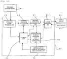
- Fig. 3 is a functional block diagram illustrating details of the control device 90.
- the control device 90 includes various functional blocks such as a pressure signal process unit 98 that calculates feature variables in a digital signal of a pressure signal from the A/D converter 54a in the respective dispensing mechanisms 50, 60, and 70, a storage unit 93 that stores various information items used in operations of the automatic analyzer such as the analysis process or the abnormality determination process, a statistic distance calculation unit 94 that calculates a statistic distance which is an index obtained by quantifying similarity between two events represented by multiple feature variables, a determination-purpose reference data suitability verification unit 95 that verifies whether the determination-purpose reference data stored in the storage unit 93 in order to be used in the abnormality determination process of the dispensing process is suitable for accurate abnormality detection, an abnormal dispensing determination unit 97 that performs the abnormality determination process of the dispensing process by using the determination-purpose reference data which is verified as suitable determination-purpose reference data through the determination-purpose reference data suitability verification unit 95 and the determination-
- control device 90 includes a control instruction unit 99 (to be described later) that controls the reaction disk 40, the first reagent disk 20, the second reagent disk 30, the sample disk 10, the dispensing mechanism 50, 60, 70, and the photometric mechanism 80.
- qualitative/quantitative analysis is performed by adding a reagent specifically reacting to a specific ingredient contained in the specimen such as blood or urine, by causing the reagent to react therewith, and by measuring optical density of the reaction liquid.
- an analysis target specimen (sample) is contained in the specimen container 11, and the specimen container 11 is mounted on the sample disk 10.
- Information (analysis items, types of reagent, or the like) required for the analysis process of each specimen is input by the input device 91 and is stored in the control device 90 in advance.
- a determined amount of reagent is aspirated from the reagent containers 21 and 31 by using the first and second reagent dispensing mechanisms 60 and 70, and is discharged to the reaction container 41 of the reaction disk 40, thereby performing dispensing and causing the stirring mechanism 42 to performing stirring.
- a type, amount, or timing of the reagent to be dispensed by the first and second reagent dispensing mechanisms 60 and 70 is determined in advance depending on a type or analysis items of the specimen.
- the reaction disk 40 is periodically and repeatedly rotated and stopped.
- Photometry is performed at a timing when the reaction container 41 passes the photometric mechanism 80 (that is, between the light source 81 and the spectroscopic detector 82).
- the photometry is repeatedly performed by the spectroscopic detector 82 during a predetermined reaction time period.
- the cleaning mechanism 43 cleans the reaction container 41 which completes analysis.
- the photometry is also performed on the multiple specimen containers 41 in parallel by the photometric mechanism 80.
- the detection result obtained by the photometric mechanism 80 is sent to the control device 90, concentration of the ingredient is calculated depending on a type of the analysis, and is displayed on the display device 92.
- sample dispensing mechanism 50 will be described as a representative of the dispensing mechanisms 50, 60, and 70.
- the specimen In the dispensing process (that is, dispensing process of the specimen) performed by the sample dispensing mechanism 50, in a state where the dispensing probe 51 is dipped in the specimen which is a dispensing target, the specimen is aspirated and discharged to the predetermined reaction container 41, thereby performing the dispensing.
- the control device 90 Before the specimen is aspirated, the control device 90 first opens the valve 58, fills the inside of the dispensing channel 53 of the dispensing probe 51 with the system liquid 51b supplied from the pump 59, and closes the valve 58. Then, in a state where a distal end of the dispensing probe 51 is located in the air, the drive mechanism 56 operates the plunger 55 to be lowered, and the separated air 51c is aspirated.
- the dispensing probe 51 is lowered into the specimen container 11.
- the plunger 55 is further operated to be lowered.
- the specimen is aspirated into the throttle portion 52 and the dispensing channel 53 of the dispensing probe 51.
- the drive mechanism 56 operates the plunger 55 to be raised, and the specimen is discharged until the specimen reaches the separated air 51c.
- the control device 90 performs an abnormality determination process for determining whether or not the respective dispensing mechanisms 50, 60, and 70 are abnormal, based on the detection result of the pressure sensor 54 (that is, a pressure waveform during the aspirating and the discharging) .
- the analysis process is temporarily stopped, and causes the display device 92 to display an alarm. In this manner, an operator is notified of the alarm so as to urge a recovery operation.
- any one among re-dispensing after removing a cause of abnormality occurrence, performing analysis on another specimen, stopping the device, and the like may be selected.
- the dispensing probe 51 After discharging the specimen, the dispensing probe 51 is cleaned by the system liquid 51b flowing in response to opening and closing of the valve 58, and is provided for the subsequent dispensing process.
- the abnormality determination process is a process for determining whether the respective dispensing mechanisms 50, 60, and 70 are abnormal during the dispensing process.
- the statistic distance calculation unit 94 acquires a pressure waveform (that is, the detection result of the pressure sensor 54) when each dispensing nozzle of the respective dispensing mechanisms 50, 60, and 70 aspirates and discharges a target (specimen or reagent), and calculates a statistic distance by using the determination-purpose reference data which is stored in the storage unit 93 and whose suitability is verified in advance so that the abnormality detection normally functions.
- Embodiment 1 a case where the Mahalanobis distance is employed as the statistic distance used in the statistic distance calculation unit 94 will be described as an example.
- the abnormal dispensing determination unit 97 compares the statistic distance calculated by the statistic distance calculation unit 94 with a threshold value stored in the storage unit 93, and determines abnormal dispensing of the respective dispensing mechanisms 50, 60, and 70, based on the comparison result.
- the threshold value stored in the storage unit 93 is determined in advance depending on each dispensing process target and each dispensing amount.
- the statistic distance is an index obtained by quantifying similarity between two events represented by multiple feature variables.
- calculation is performed on how far target data is away from a group of known data prepared in advance.
- a calculation method of the Mahalanobis distance will be described as an example of the statistic distance.
- Fig. 4 is a table schematically illustrating an example of a group of the known data.
- each data of the n (1 to n) number of events has the k (1 to k) number of feature variables (n and k are positive integers).
- Equation (1) when the respective feature variables of the target data are set to y 1 , y 2 , ⁇ , y k , average values of the respective feature variables of known data x nk are set to z 1 , z 2 , ⁇ , z k , and standard deviations are set to ⁇ 1 , ⁇ 2 , ⁇ , ⁇ k .
- X t y i ⁇ z i ⁇ i
- a Mahalanobis distance D M of the target data from the group of the known data is expressed by Equation (2) below.
- D M 1 k X 1 ⁇ X k A X 1 ⁇ X k
- Equation (2) a product of a feature variable matrix of evaluation data and a correlation matrix of the determination-purpose reference data is divided by k, and the square root is calculated, thereby calculating the Mahalanobis distance D M .
- the calculation method of the statistic distance which can be applied to Embodiment 1 includes a calculation method of a Euclidean distance, a standard Euclidean distance, a Manhattan distance, a Chebyshev distance, and a Minkowski distance, and multivariate normal density.
- the determination-purpose reference data used for the abnormality determination process is verified as suitable so that predetermined performance in detecting the abnormal dispensing can be maintained in the determination-purpose reference data suitability verification unit 95. In a case where it is determined as unsuitable for the abnormal dispensing detection, it is determined whether or not component replacement or device adjustment is required.
- the suitability of the determination-purpose reference data is verified for any one of the sample dispensing mechanism 50, the first reagent dispensing mechanism 60, and the second reagent dispensing mechanism 70, as a verification target.
- Fig. 5 is a flowchart with regard to a series of processes in the determination-purpose reference data suitability verification unit 95 of the control device 90.
- Fig. 8 is an internal configuration block diagram of the control device 90, and is a view clearly illustrating a relationship of transmitting an instruction signal and data between internal configuration elements illustrated in Fig. 3 .
- a series of processes in verifying the suitability of the determination-purpose reference data which is illustrated in Fig. 5 can be performed by an operator or a service engineer through a graphical user interface (GUI) of the control device 90, and is performed independent of a usual analysis operation before the automatic analyzer starts to perform the analysis process.
- GUI graphical user interface
- the series of processes can also be automatically performed by setting the series of processes in advance.
- channel inner pressure fluctuation data in normal dispensing and abnormal dispensing conditions is acquired.
- the abnormal dispensing condition described herein includes a case of aspirating bubbles on the liquid level of the specimen or the reagent (bubble aspirating), a case of aspirating only the air (air aspirating), or a case of aspirating the specimen having high viscosity.
- a stopping position of the probe in the vertical direction is controlled in order to realize reliable data acquisition.
- the specimen or the reagent for verifying the suitability of the determination-purpose reference data is installed in advance in each sample disk or each reagent disk.
- the liquid of the specimen or the reagent for verifying the suitability it is conceivable to use those which simulate the minimum viscosity or the maximum viscosity available in operation, but the liquid is not limited thereto.
- a dispensing amount serving as a data acquisition target is set to the amount of both ends in switching operation patterns of a syringe drive motor (dispensing amount for 8 times in a case of 4 operation patterns). The normal and abnormal data are acquired for each dispensing amount. In order to improve reliability, two or three sets may be repeated.
- Fig. 6 is a view illustrating an example of operation conditions for acquiring the normal and abnormal data used in verifying the suitability of the determination-purpose reference data in STEP 1.
- sequence numbers in the condition are 1 to 12.
- a normal operation is performed in 8 rows, and an abnormal operation (air aspirating) is performed in only 4 rows.
- a setting amount has 3 types of 10 ⁇ L, 49 ⁇ L, 50 ⁇ L, and 100 ⁇ L.
- An aspirating target (pseudo-reagent) has 2 types of purified water and aqueous solution containing glycerin 30%. Each sequence is performed 5 times.
- the aspirated target (pseudo-reagent or pseudo-specimen) is not necessarily discharged to the reaction container 41, and may be discharged to a specific place such as a cleaning tank in a cleaning mechanism.
- Fig. 7 illustrates an acquired waveform example of channel inner pressure data in normal and abnormal conditions which are used for verifying the suitability of the determination-purpose reference data in STEP 1.
- a solid line waveform represents an example of a normal case
- a broken line waveform represents an example of an air aspirating (abnormal) case.
- An aspirating section is approximately 125 ms from when aspirating starts. As illustrated in Fig. 7 , in the aspirating section, there is a pressure difference of approximately 2,000 Pa between normal aspirating and abnormal aspirating (air aspirating).
- a feature variable is calculated for a digital signal of a pressure waveform under the normal dispensing and abnormal dispensing conditions, which is a pressure sensor signal sent from the A/D converter 54a by the pressure signal process unit 98 of the control device 90.
- the feature variable described herein includes a pressure average value at every fixed time interval or appearing timing of a minimum point and a maximum point of pressure fluctuations which appear when the plunger 55 starts to be operated and stops the operation.
- the statistic distance calculation unit 94 calculates a statistic distance D M between the determination-purpose reference data stored in the storage unit 93 and each data acquired in STEPS 1 and 2.
- the determination-purpose reference data includes a normal data set and an abnormal data set, or any one of both data sets.
- the statistic distance D M from the normal data set configuring the determination-purpose reference data is calculated.
- the statistic distance D M from the abnormal data set configuring the reference database is calculated.
- the abnormal dispensing determination unit 97 compares the statistic distance D M calculated by the statistic distance calculation unit 94 with a threshold value stored in the storage unit 93 in advance, and determines whether or not the abnormal dispensing is present.
- the determination-purpose reference data suitability verification unit 95 determines whether or not the result determined by the abnormal dispensing determination unit 97 coincides with normality or abnormality of the determination-purpose reference data as illustrated in Fig. 6 . In a case where both coincide with each other, it is determined that the abnormality detection function is normal, and the result is transmitted to the control instruction unit 99.
- the control instruction unit 99 switches the automatic analyzer to a standby state. In this case, the control instruction unit 99 can cause the display device 92 to display that the abnormality detection function is normal.
- the determination-purpose reference data suitability verification unit 95 determines a possibility that the abnormality detection function may not be normal, and transmits the result to the control instruction unit 99. Then, the process proceeds to STEP 4.
- the control instruction unit 99 acquires the determination-purpose reference data. Through the same operation as that in STEP 1, the control instruction unit 99 acquires the data under the normal and abnormal conditions. A dispensing amount of the acquired data can be optionally set. It is possible to set only the dispensing amount of items having an analysis parameter registered therein or only the dispensing amount of selected items.
- the reference data acquired herein is added to the existing determination-purpose reference data so as to prepare temporary determination-purpose reference data.
- the prepared temporary determination-purpose reference data is stored in the storage unit 93 via the pressure signal process unit 98.
- the reference data acquired herein can also be used in preparing the temporary determination-purpose reference data. These operations can be automatically performed in such a way that the control instruction unit 99 controls each unit.
- the reference data may be prepared by acquiring any one data under the normal condition or under the abnormal condition.
- the statistic distance calculation unit 94 calculates the statistic distance D M between the data acquired in STEPS 1 and 2 and the temporary determination-purpose reference data prepared in STEP 4. Calculation content is the same as that in STEP 3.
- the determination-purpose reference data suitability verification unit 95 compares the statistic distance D M calculated by the statistic distance calculation unit 94 with a threshold value stored in the storage unit 93 in advance. If the difference is smaller than a fixed value, it is determined that the abnormality detection function is normal, and the result is transmitted to the control instruction unit 99.
- the control instruction unit 99 switches the automatic analyzer to a standby state.
- the determination-purpose reference data suitability verification unit 95 determines a possibility that the automatic analyzer may have an abnormal component or that a failure may occur in the automatic analyzer, and transmits the result to the control instruction unit 99.
- control instruction unit 99 causes the display device 92 to display an alarm so as to urge component replacement or adjustment of the automatic analyzer.
- the control instruction unit 99 performs the series of processes again from STEP 4, and performs a determination process again so as to determine whether or not the determination is wrong.
- Fig. 9 is an operation flowchart illustrating the abnormality determination process of the dispensing mechanism during the analysis process operation.
- the operation of the sample dispensing mechanism 50 will be described as an example.
- the abnormality determination process is similarly performed on the first reagent dispensing mechanism 60 and the second reagent dispensing mechanism 70.
- the control instruction unit 99 of the control device 90 causes the sample dispensing mechanism 50 to perform an aspirating operation in a dispensing step (STEP 1), and causes the pressure signal process unit 98 to calculates the feature variable of the target data with regard to the digital signal of the pressure waveform of the pressure sensor 54 which is sent from the A/D converter 54a (STEP 2). Subsequently, the statistic distance calculation unit 94 calculates the statistic distance D M from the determination-purpose reference data which is selected in advance from the target data (STEP 3).
- the abnormal dispensing determination unit 97 determines whether or not the statistic distance D M is smaller than a predetermined threshold value stored in the storage unit 93 (STEP 4). In a case where the determination result is NO in STEP 4, a recovery process is performed (STEP 5), and the process is completed.
- the recovery process is a process in which the abnormal dispensing determination unit 97 issues information relating to abnormal aspirating, and in which the control instruction unit 99 performs an operation for an alarm process and for proceeding to the subsequent specimen process.
- the drive mechanism 56 and the plunger 55 perform a discharge operation in accordance with the instruction of the control instruction unit 99 (STEP 6), and determines whether or not the subsequent dispensing is to be performed (STEP 7).
- the process returns to the process in STEP 1.
- the determination result is NO, that is, in a case where the subsequent dispensing is not to be performed, the process is completed.
- the process is similarly performed on the pressure fluctuation during the discharge operation.
- the output values of the pressure sensor in the automatic analyzer fluctuate even if the same specimen or the same reagent is dispensed.
- the reference database stored in advance is determined as unsuitable through the abnormal dispensing detection in the device, thereby resulting in a problem in that detection performance of the abnormal dispensing becomes poor.
- the data is acquired under the predetermined conditions (normal condition and abnormal condition) so as to verify whether or not the determination-purpose reference data stored in the storage unit 93 is suitable for the abnormality detection function to be properly fulfilled. Then, in a case where it is determined that the determination-purpose reference data is not suitable for the abnormality detection function to be properly fulfilled, the temporary determination-purpose reference data is prepared.
- the prepared temporary determination-purpose reference data is compared with the data previously acquired under the predetermined conditions (normal condition and abnormal condition). In a case where the difference therebetween is greater than the predetermined threshold value, a possibility is determined that the automatic analyzer may have an abnormal component or that a failure may occur in the automatic analyzer, and the result is transmitted to the control instruction unit 99. An alarm is displayed so as to urge component replacement or adjustment of the automatic analyzer. Alternatively, the series of processes is performed again, and a determination process is performed again so as to determine whether or not the determination is wrong.
- the automatic analyzer which can accurately detect a state where component replacement or device adjustment is required, without being affected by a time-dependent change or replacement of each component configuring a channel.
- Embodiment 1 is an example of the automatic analyzer which can accurately detect a state where the component replacement or the device adjustment is required.
- Embodiment 2 is an example which can improve analysis accuracy by updating the determination-purpose reference data to optimized data and optimizing a function to detect the abnormal dispensing.
- Embodiment 2 an overall configuration of the automatic analyzer, and reagent and sample dispensing mechanisms are the same as those in Embodiment 1. Thus, illustration and detailed description will be omitted.
- Fig. 10 is a functional block diagram of the control device 90 according to Embodiment 2.
- a point different from the functional block diagram illustrated in Fig. 3 according to Embodiment 1 is that the determination reference data updating unit 96 is added to the configuration in the example illustrated in Fig. 3 .
- the control device 90 also includes the analysis process unit 100.
- illustration will be omitted. The omitted illustration is similarly applied to Embodiments 3 and 4 to be described later.
- FIG. 11 illustrates a flowchart with regard to a series of processes of the control device 90.
- a point different from the flowchart illustrated in Fig. 5 according to Embodiment 1 is that STEP 6 is added to all of STEPS 1 to 3, 3A, 4, 5, 5A, and 7 illustrated in Fig. 5 .
- Fig. 12 is an internal configuration block diagram of the control device 90, and is a view clearly illustrating a relationship of transmitting an instruction signal and data between internal configuration elements illustrated in Fig. 10 .
- Fig. 12 corresponds to the internal configuration block diagram in Fig. 8 according to Embodiment 1.
- an example illustrated in Fig. 12 includes the entire example illustrated in Fig. 8 .
- the determination-purpose reference data updating unit 96 is added thereto.
- the determination-purpose reference data suitability verification unit 95 causes the process to proceed to STEP 6, if a difference between the statistic distance D M and a threshold value stored in the storage unit 93 in advance is smaller than a fixed value.
- the determination-purpose reference data updating unit 96 instructed by the determination-purpose reference data suitability verification unit 95 to update the determination-purpose reference data updates the temporary determination-purpose reference data prepared in STEP 4 to formal determination-purpose reference data, and stores the formal determination-purpose reference data in the storage unit 93.
- Embodiment 2 An abnormality determination process according to Embodiment 2 is the same as that according to Embodiment 1, and thus, detailed description will be omitted.
- Embodiment 2 of the present invention it is possible to obtain the same advantageous effect as that according to Embodiment 1.
- Embodiment 2 is configured so that the determination-purpose reference data is updated to optimized data. Accordingly, the abnormal dispensing can be always accurately detected without being affected by a time-dependent change or replacement of each component configuring a channel. Therefore, it is possible to obtain a very reliable analysis result.
- the temporary determination-purpose reference data is also prepared by adding the existing determination-purpose reference data thereto.
- the prepared temporary determination-purpose reference data is stored in the storage unit 93 via the pressure signal process unit 98.
- the temporary determination-purpose reference data can also be prepared by using only the reference data acquired herein.
- multiple determination-purpose reference data items are stored in the storage unit 93.
- the determination-purpose reference data item to be used is fixed to one optimized determination-purpose reference data item.
- the determination-purpose reference data item is updated to an optimized data item out of other determination-purpose reference data items.
- Embodiment 3 the overall configuration of the automatic analyzer, the reagent and sample dispensing mechanisms, and the abnormality process during the analysis operation are the same as those in Embodiment 1. Thus, illustration and detailed description will be omitted.
- control device 90 is the same as that in Embodiment 2. Thus, illustration and detailed description will be omitted.
- Fig. 13 is a flowchart with regard to a series of processes in the control device 90 according to Embodiment 3.
- STEPS 1 and 2 in Fig. 13 are the same as STEPS 1, 2, and 3 illustrated in Fig. 12 in Embodiment 2.
- STEP 3A in Fig. 13 if the determination is wrong, the process proceeds to STEP 5 so as to determine whether or not a process for verifying the suitability is completed for all of the multiple determination-purpose reference data items.
- STEP 5 if the process for verifying the suitability is not completed for all of the multiple determination-purpose reference data items, the process proceeds to STEP 7 so as to acquire the subsequent determination-purpose reference data item stored in the storage unit 93.
- the subsequent determination-purpose reference data item is set as the temporary determination-purpose reference data item, and the process returns to STEP 3.
- the determination-purpose reference data updating unit 96 updates the temporary determination-purpose reference data item in which the determination is not wrong, as the determination-purpose reference data item, and stores the updated data item in the storage unit 93.
- the updating described herein includes a case where as long as the determination of the previously used determination-purpose reference data is not wrong, the determination-purpose reference data item is continuously used as the formal the determination-purpose reference data item.
- STEP 5 in a case where all of the determination-purpose reference data items are completed, it means that there is no suitable data item in the multiple determination-purpose reference data items. Accordingly, the process proceeds to STEP 6.
- the control instruction unit 99 causes the display device 92 to display the component replacement or the device adjustment as an alarm.
- Embodiment 3 it is also possible to obtain the same advantageous effect as that according to Embodiment 2.
- Embodiment 4 is an example in which Embodiment 2 and Embodiment 3 are combined with each other.
- Figs. 14 and 15 are operation flowcharts according to Embodiment 4.
- Fig. 14 has the same STEPS as STEPS 1 to 3, 3A, 4, 5, and 7 in the flowchart illustrated in Fig. 13 in Embodiment 3.
- Fig. 15 illustrates STEPS 8 to 12 subsequent to STEP 5 in Fig. 14 .
- STEPS 8, 9, and 11 in Fig. 15 correspond to STEPS 4, 5, and 5A in Fig. 11 according to Embodiment 2.
- STEPS 10 and 12 in Fig. 15 correspond to STEPS 6 and 7 in Fig. 11 .
- Embodiment 4 multiple determination-purpose reference data items are stored in the storage unit 93.
- the determination-purpose reference data item to be used is fixed to one optimized determination-purpose reference data item.
- the determination-purpose reference data item is updated to the affirmative data item.
- Embodiment 4 in a case where the suitability is denied when the suitability of the determination-purpose reference data is verified, similarly to Embodiment 2, the determination-purpose reference data is acquired, and is set to new temporary determination-purpose reference data (STEP 8).
- the statistic distance calculation unit 94 calculates the statistic distance D M between the data acquired in STEPS 1 and 2 and the temporary determination-purpose reference data prepared in STEP 8.
- the determination-purpose reference data suitability verification unit 95 compares the statistic distance D M calculated by the statistic distance calculation unit 94 with the threshold value stored in the storage unit 93 in advance. If the difference therebetween is smaller than a fixed value, it is determined that the abnormality detection function is normal.
- the determination-purpose reference data updating unit 96 instructed by the determination-purpose reference data suitability verification unit 95 to update the determination-purpose reference data updates the temporary determination-purpose reference data prepared in STEP 8 to formal determination-purpose reference data, and stores the formal determination-purpose reference data in the storage unit 93.
- the determination-purpose reference data suitability verification unit 95 determines a possibility that the automatic analyzer may have an abnormal component or that a failure may occur in the automatic analyzer, and transmits the result to the control instruction unit 99.
- control instruction unit 99 causes the display device 92 to display an alarm so as to urge component replacement or adjustment of the automatic analyzer.
- the series of processes from STEP 8 is performed again, and a determination process is performed again so as to determine whether or not the determination is wrong.
- Embodiment 4 the overall configuration of the automatic analyzer, the reagent and sample dispensing mechanisms, and the abnormality process during the analysis operation are the same as those in Embodiment 2. Thus, illustration and detailed description will be omitted.
- control device 90 is also the same as that according to Embodiment 2. Thus, illustration and detailed description will be omitted.
- Embodiment 4 it is also possible to obtain the same advantageous effect as that according to Embodiment 2.
- the abnormal dispensing can be determined, based on not only an aspirating waveform but also a discharge waveform of the sample or the reagent.
- the suitability of the determination-purpose reference data is determined by acquiring both data items of the data item in a case of the normal dispensing in STEP 1 in Figs. 5 , 13 , and 14 and the pressure data items in a case of the abnormal dispensing.
- the suitability of the determination-purpose reference data can also be determined by acquiring either the data item in the case of the normal dispensing or the pressure data items in the case of the abnormal dispensing.
Applications Claiming Priority (2)
| Application Number | Priority Date | Filing Date | Title |
|---|---|---|---|
| JP2014101657 | 2014-05-15 | ||
| PCT/JP2015/062180 WO2015174226A1 (ja) | 2014-05-15 | 2015-04-22 | 自動分析装置 |
Publications (3)
| Publication Number | Publication Date |
|---|---|
| EP3144678A1 true EP3144678A1 (de) | 2017-03-22 |
| EP3144678A4 EP3144678A4 (de) | 2017-12-27 |
| EP3144678B1 EP3144678B1 (de) | 2021-09-01 |
Family
ID=54479770
Family Applications (1)
| Application Number | Title | Priority Date | Filing Date |
|---|---|---|---|
| EP15792381.4A Active EP3144678B1 (de) | 2014-05-15 | 2015-04-22 | Automatisierte analysevorrichtung |
Country Status (5)
| Country | Link |
|---|---|
| US (1) | US10288637B2 (de) |
| EP (1) | EP3144678B1 (de) |
| JP (1) | JP6602753B2 (de) |
| CN (1) | CN106461693B (de) |
| WO (1) | WO2015174226A1 (de) |
Cited By (1)
| Publication number | Priority date | Publication date | Assignee | Title |
|---|---|---|---|---|
| EP3432003A4 (de) * | 2016-03-16 | 2019-12-11 | Hitachi High-Technologies Corporation | Automatisierte analysevorrichtung |
Families Citing this family (15)
| Publication number | Priority date | Publication date | Assignee | Title |
|---|---|---|---|---|
| JP6654881B2 (ja) * | 2015-12-09 | 2020-02-26 | 株式会社日立ハイテクノロジーズ | 自動分析装置及び自動分析装置の異常判定方法 |
| JP6908631B2 (ja) * | 2017-02-07 | 2021-07-28 | 株式会社日立ハイテク | 自動分析装置 |
| EP3581936B1 (de) * | 2017-02-07 | 2022-07-13 | Hitachi High-Tech Corporation | Automatische analysevorrichtung |
| JP7011904B2 (ja) * | 2017-07-31 | 2022-01-27 | 株式会社日立ハイテク | 装置、試料における気泡の状態の判別方法、及び分析システム |
| JP6762927B2 (ja) * | 2017-12-19 | 2020-09-30 | 株式会社日立ハイテク | 信号処理装置及び信号処理方法 |
| JP6946202B2 (ja) * | 2018-01-15 | 2021-10-06 | 株式会社日立ハイテク | 自動分析装置 |
| JP6936921B2 (ja) * | 2018-07-26 | 2021-09-22 | 株式会社日立ハイテク | 分散制御システム、自動分析装置、および自動分析システム |
| CN112912736A (zh) * | 2018-10-25 | 2021-06-04 | 株式会社日立高新技术 | 自动分析装置 |
| JP7184636B2 (ja) * | 2018-12-27 | 2022-12-06 | 三菱重工業株式会社 | データ選別装置及び方法、ならびに監視診断装置 |
| EP3922996B1 (de) * | 2019-02-08 | 2023-08-16 | Hitachi High-Tech Corporation | Automatische analysevorrichtung |
| JP7181821B2 (ja) * | 2019-03-15 | 2022-12-01 | 株式会社日立ハイテク | 自動分析装置 |
| DE102019118205A1 (de) * | 2019-07-05 | 2021-01-07 | Dionex Softron Gmbh | Zustandsbestimmung eines fluidischen Systems |
| CN110456089B (zh) * | 2019-08-28 | 2023-04-25 | 迈克医疗电子有限公司 | 全自动样本分析仪及其加试剂方法、计算装置 |
| EP4050342A4 (de) * | 2019-10-24 | 2023-12-20 | Hitachi High-Tech Corporation | Vorrichtung und verfahren zur automatischen analyse von reagenziendispension |
| CN112986592B (zh) * | 2019-12-13 | 2024-02-06 | 深圳迈瑞生物医疗电子股份有限公司 | 体外诊断设备及其进给异常的判定方法和存储介质 |
Family Cites Families (14)
| Publication number | Priority date | Publication date | Assignee | Title |
|---|---|---|---|---|
| JPH06331630A (ja) * | 1993-05-25 | 1994-12-02 | Daikin Ind Ltd | キャリブレーション結果判定方法およびキャリブレーション結果処理方法 |
| JPH11258244A (ja) * | 1998-03-16 | 1999-09-24 | Olympus Optical Co Ltd | 分注装置の異常検知方法および異常検知装置 |
| US7027935B2 (en) | 2002-08-07 | 2006-04-11 | Hitachi High Technologies Corp. | Sample dispensing apparatus and automatic analyzer using the same |
| JP2008002897A (ja) * | 2006-06-21 | 2008-01-10 | Olympus Corp | 分注装置および自動分析装置 |
| JPWO2008155820A1 (ja) * | 2007-06-19 | 2010-08-26 | ベックマン・コールター・インコーポレーテッド | 異常特定方法および分析装置 |
| JP4538478B2 (ja) * | 2007-08-31 | 2010-09-08 | 株式会社日立ハイテクノロジーズ | 自動分析装置 |
| JP2009198308A (ja) * | 2008-02-21 | 2009-09-03 | Olympus Corp | 攪拌装置および分析装置 |
| CN101881706B (zh) * | 2010-07-05 | 2014-04-02 | 深圳迈瑞生物医疗电子股份有限公司 | 一种采样设备及方法 |
| CN103540518B (zh) * | 2010-07-23 | 2015-07-08 | 贝克曼考尔特公司 | 化验盒 |
| JP5277214B2 (ja) * | 2010-07-27 | 2013-08-28 | 株式会社日立ハイテクノロジーズ | 自動分析装置 |
| JP5992668B2 (ja) | 2011-07-22 | 2016-09-14 | 東芝メディカルシステムズ株式会社 | 自動分析装置 |
| US9874471B2 (en) | 2012-01-11 | 2018-01-23 | Siemens Healthcare Diagnostics Inc. | Liquid transfer systems and methods of calibration thereof by performing air aspirations |
| JP2013185912A (ja) | 2012-03-07 | 2013-09-19 | Hitachi High-Technologies Corp | 自動分析装置 |
| JP5899075B2 (ja) | 2012-07-20 | 2016-04-06 | 株式会社日立ハイテクノロジーズ | 自動分析装置 |
-
2015
- 2015-04-22 US US15/310,808 patent/US10288637B2/en active Active
- 2015-04-22 EP EP15792381.4A patent/EP3144678B1/de active Active
- 2015-04-22 CN CN201580026990.9A patent/CN106461693B/zh active Active
- 2015-04-22 JP JP2016519186A patent/JP6602753B2/ja active Active
- 2015-04-22 WO PCT/JP2015/062180 patent/WO2015174226A1/ja active Application Filing
Cited By (2)
| Publication number | Priority date | Publication date | Assignee | Title |
|---|---|---|---|---|
| EP3432003A4 (de) * | 2016-03-16 | 2019-12-11 | Hitachi High-Technologies Corporation | Automatisierte analysevorrichtung |
| US10989708B2 (en) | 2016-03-16 | 2021-04-27 | Hitachi High-Tech Corporation | Automated analysis device |
Also Published As
| Publication number | Publication date |
|---|---|
| US20170089938A1 (en) | 2017-03-30 |
| CN106461693A (zh) | 2017-02-22 |
| WO2015174226A1 (ja) | 2015-11-19 |
| JPWO2015174226A1 (ja) | 2017-04-20 |
| US10288637B2 (en) | 2019-05-14 |
| JP6602753B2 (ja) | 2019-11-06 |
| CN106461693B (zh) | 2018-01-30 |
| EP3144678B1 (de) | 2021-09-01 |
| EP3144678A4 (de) | 2017-12-27 |
Similar Documents
| Publication | Publication Date | Title |
|---|---|---|
| EP3144678B1 (de) | Automatisierte analysevorrichtung | |
| EP2952902B1 (de) | Automatisierte analysevorrichtung | |
| EP2752667B1 (de) | Autoanalysegerät und analyseverfahren | |
| EP2876449B1 (de) | Automatische analysevorrichtung | |
| EP3264102B1 (de) | Automatische analysevorrichtung | |
| EP3101431B1 (de) | Automatische analytische vorrichtung | |
| JP6567890B2 (ja) | 自動分析装置 | |
| EP3859343A1 (de) | Automatisierte analysevorrichtung | |
| JP6654881B2 (ja) | 自動分析装置及び自動分析装置の異常判定方法 | |
| EP4354147A1 (de) | Ausgabevorrichtung, automatische analysevorrichtung und ausgabeverfahren | |
| CN112955749B (zh) | 异常判定方法和自动分析装置 | |
| EP4317982A1 (de) | Automatisierte analysevorrichtung | |
| EP3808426A1 (de) | Techniken zur überprüfung des zustands von analysatoren |
Legal Events
| Date | Code | Title | Description |
|---|---|---|---|
| STAA | Information on the status of an ep patent application or granted ep patent |
Free format text: STATUS: THE INTERNATIONAL PUBLICATION HAS BEEN MADE |
|
| PUAI | Public reference made under article 153(3) epc to a published international application that has entered the european phase |
Free format text: ORIGINAL CODE: 0009012 |
|
| STAA | Information on the status of an ep patent application or granted ep patent |
Free format text: STATUS: REQUEST FOR EXAMINATION WAS MADE |
|
| 17P | Request for examination filed |
Effective date: 20161213 |
|
| AK | Designated contracting states |
Kind code of ref document: A1 Designated state(s): AL AT BE BG CH CY CZ DE DK EE ES FI FR GB GR HR HU IE IS IT LI LT LU LV MC MK MT NL NO PL PT RO RS SE SI SK SM TR |
|
| AX | Request for extension of the european patent |
Extension state: BA ME |
|
| DAV | Request for validation of the european patent (deleted) | ||
| DAX | Request for extension of the european patent (deleted) | ||
| A4 | Supplementary search report drawn up and despatched |
Effective date: 20171129 |
|
| RIC1 | Information provided on ipc code assigned before grant |
Ipc: G01N 35/00 20060101AFI20171122BHEP Ipc: G01N 35/02 20060101ALN20171122BHEP Ipc: G01N 35/10 20060101ALI20171122BHEP Ipc: G01L 19/00 20060101ALN20171122BHEP Ipc: G01N 1/14 20060101ALN20171122BHEP |
|
| STAA | Information on the status of an ep patent application or granted ep patent |
Free format text: STATUS: EXAMINATION IS IN PROGRESS |
|
| 17Q | First examination report despatched |
Effective date: 20191115 |
|
| RAP1 | Party data changed (applicant data changed or rights of an application transferred) |
Owner name: HITACHI HIGH-TECH CORPORATION |
|
| STAA | Information on the status of an ep patent application or granted ep patent |
Free format text: STATUS: EXAMINATION IS IN PROGRESS |
|
| GRAP | Despatch of communication of intention to grant a patent |
Free format text: ORIGINAL CODE: EPIDOSNIGR1 |
|
| STAA | Information on the status of an ep patent application or granted ep patent |
Free format text: STATUS: GRANT OF PATENT IS INTENDED |
|
| RIC1 | Information provided on ipc code assigned before grant |
Ipc: G01L 19/00 20060101ALN20210219BHEP Ipc: G01N 35/10 20060101ALI20210219BHEP Ipc: G01N 1/14 20060101ALN20210219BHEP Ipc: G01N 35/00 20060101AFI20210219BHEP Ipc: G01N 35/02 20060101ALN20210219BHEP |
|
| RIC1 | Information provided on ipc code assigned before grant |
Ipc: G01N 35/10 20060101ALI20210301BHEP Ipc: G01N 35/02 20060101ALN20210301BHEP Ipc: G01L 19/00 20060101ALN20210301BHEP Ipc: G01N 1/14 20060101ALN20210301BHEP Ipc: G01N 35/00 20060101AFI20210301BHEP |
|
| INTG | Intention to grant announced |
Effective date: 20210316 |
|
| GRAS | Grant fee paid |
Free format text: ORIGINAL CODE: EPIDOSNIGR3 |
|
| GRAA | (expected) grant |
Free format text: ORIGINAL CODE: 0009210 |
|
| STAA | Information on the status of an ep patent application or granted ep patent |
Free format text: STATUS: THE PATENT HAS BEEN GRANTED |
|
| AK | Designated contracting states |
Kind code of ref document: B1 Designated state(s): AL AT BE BG CH CY CZ DE DK EE ES FI FR GB GR HR HU IE IS IT LI LT LU LV MC MK MT NL NO PL PT RO RS SE SI SK SM TR |
|
| REG | Reference to a national code |
Ref country code: GB Ref legal event code: FG4D |
|
| REG | Reference to a national code |
Ref country code: CH Ref legal event code: EP Ref country code: AT Ref legal event code: REF Ref document number: 1426759 Country of ref document: AT Kind code of ref document: T Effective date: 20210915 |
|
| REG | Reference to a national code |
Ref country code: DE Ref legal event code: R096 Ref document number: 602015072915 Country of ref document: DE |
|
| REG | Reference to a national code |
Ref country code: IE Ref legal event code: FG4D |
|
| REG | Reference to a national code |
Ref country code: LT Ref legal event code: MG9D |
|
| REG | Reference to a national code |
Ref country code: NL Ref legal event code: MP Effective date: 20210901 |
|
| PG25 | Lapsed in a contracting state [announced via postgrant information from national office to epo] |
Ref country code: ES Free format text: LAPSE BECAUSE OF FAILURE TO SUBMIT A TRANSLATION OF THE DESCRIPTION OR TO PAY THE FEE WITHIN THE PRESCRIBED TIME-LIMIT Effective date: 20210901 Ref country code: FI Free format text: LAPSE BECAUSE OF FAILURE TO SUBMIT A TRANSLATION OF THE DESCRIPTION OR TO PAY THE FEE WITHIN THE PRESCRIBED TIME-LIMIT Effective date: 20210901 Ref country code: NO Free format text: LAPSE BECAUSE OF FAILURE TO SUBMIT A TRANSLATION OF THE DESCRIPTION OR TO PAY THE FEE WITHIN THE PRESCRIBED TIME-LIMIT Effective date: 20211201 Ref country code: BG Free format text: LAPSE BECAUSE OF FAILURE TO SUBMIT A TRANSLATION OF THE DESCRIPTION OR TO PAY THE FEE WITHIN THE PRESCRIBED TIME-LIMIT Effective date: 20211201 Ref country code: LT Free format text: LAPSE BECAUSE OF FAILURE TO SUBMIT A TRANSLATION OF THE DESCRIPTION OR TO PAY THE FEE WITHIN THE PRESCRIBED TIME-LIMIT Effective date: 20210901 Ref country code: SE Free format text: LAPSE BECAUSE OF FAILURE TO SUBMIT A TRANSLATION OF THE DESCRIPTION OR TO PAY THE FEE WITHIN THE PRESCRIBED TIME-LIMIT Effective date: 20210901 Ref country code: RS Free format text: LAPSE BECAUSE OF FAILURE TO SUBMIT A TRANSLATION OF THE DESCRIPTION OR TO PAY THE FEE WITHIN THE PRESCRIBED TIME-LIMIT Effective date: 20210901 Ref country code: HR Free format text: LAPSE BECAUSE OF FAILURE TO SUBMIT A TRANSLATION OF THE DESCRIPTION OR TO PAY THE FEE WITHIN THE PRESCRIBED TIME-LIMIT Effective date: 20210901 |
|
| REG | Reference to a national code |
Ref country code: AT Ref legal event code: MK05 Ref document number: 1426759 Country of ref document: AT Kind code of ref document: T Effective date: 20210901 |
|
| PG25 | Lapsed in a contracting state [announced via postgrant information from national office to epo] |
Ref country code: PL Free format text: LAPSE BECAUSE OF FAILURE TO SUBMIT A TRANSLATION OF THE DESCRIPTION OR TO PAY THE FEE WITHIN THE PRESCRIBED TIME-LIMIT Effective date: 20210901 Ref country code: LV Free format text: LAPSE BECAUSE OF FAILURE TO SUBMIT A TRANSLATION OF THE DESCRIPTION OR TO PAY THE FEE WITHIN THE PRESCRIBED TIME-LIMIT Effective date: 20210901 Ref country code: GR Free format text: LAPSE BECAUSE OF FAILURE TO SUBMIT A TRANSLATION OF THE DESCRIPTION OR TO PAY THE FEE WITHIN THE PRESCRIBED TIME-LIMIT Effective date: 20211202 |
|
| PG25 | Lapsed in a contracting state [announced via postgrant information from national office to epo] |
Ref country code: AT Free format text: LAPSE BECAUSE OF FAILURE TO SUBMIT A TRANSLATION OF THE DESCRIPTION OR TO PAY THE FEE WITHIN THE PRESCRIBED TIME-LIMIT Effective date: 20210901 |
|
| PG25 | Lapsed in a contracting state [announced via postgrant information from national office to epo] |
Ref country code: IS Free format text: LAPSE BECAUSE OF FAILURE TO SUBMIT A TRANSLATION OF THE DESCRIPTION OR TO PAY THE FEE WITHIN THE PRESCRIBED TIME-LIMIT Effective date: 20220101 Ref country code: SM Free format text: LAPSE BECAUSE OF FAILURE TO SUBMIT A TRANSLATION OF THE DESCRIPTION OR TO PAY THE FEE WITHIN THE PRESCRIBED TIME-LIMIT Effective date: 20210901 Ref country code: SK Free format text: LAPSE BECAUSE OF FAILURE TO SUBMIT A TRANSLATION OF THE DESCRIPTION OR TO PAY THE FEE WITHIN THE PRESCRIBED TIME-LIMIT Effective date: 20210901 Ref country code: RO Free format text: LAPSE BECAUSE OF FAILURE TO SUBMIT A TRANSLATION OF THE DESCRIPTION OR TO PAY THE FEE WITHIN THE PRESCRIBED TIME-LIMIT Effective date: 20210901 Ref country code: PT Free format text: LAPSE BECAUSE OF FAILURE TO SUBMIT A TRANSLATION OF THE DESCRIPTION OR TO PAY THE FEE WITHIN THE PRESCRIBED TIME-LIMIT Effective date: 20220103 Ref country code: NL Free format text: LAPSE BECAUSE OF FAILURE TO SUBMIT A TRANSLATION OF THE DESCRIPTION OR TO PAY THE FEE WITHIN THE PRESCRIBED TIME-LIMIT Effective date: 20210901 Ref country code: EE Free format text: LAPSE BECAUSE OF FAILURE TO SUBMIT A TRANSLATION OF THE DESCRIPTION OR TO PAY THE FEE WITHIN THE PRESCRIBED TIME-LIMIT Effective date: 20210901 Ref country code: CZ Free format text: LAPSE BECAUSE OF FAILURE TO SUBMIT A TRANSLATION OF THE DESCRIPTION OR TO PAY THE FEE WITHIN THE PRESCRIBED TIME-LIMIT Effective date: 20210901 Ref country code: AL Free format text: LAPSE BECAUSE OF FAILURE TO SUBMIT A TRANSLATION OF THE DESCRIPTION OR TO PAY THE FEE WITHIN THE PRESCRIBED TIME-LIMIT Effective date: 20210901 |
|
| REG | Reference to a national code |
Ref country code: DE Ref legal event code: R097 Ref document number: 602015072915 Country of ref document: DE |
|
| PLBE | No opposition filed within time limit |
Free format text: ORIGINAL CODE: 0009261 |
|
| STAA | Information on the status of an ep patent application or granted ep patent |
Free format text: STATUS: NO OPPOSITION FILED WITHIN TIME LIMIT |
|
| PG25 | Lapsed in a contracting state [announced via postgrant information from national office to epo] |
Ref country code: IT Free format text: LAPSE BECAUSE OF FAILURE TO SUBMIT A TRANSLATION OF THE DESCRIPTION OR TO PAY THE FEE WITHIN THE PRESCRIBED TIME-LIMIT Effective date: 20210901 Ref country code: DK Free format text: LAPSE BECAUSE OF FAILURE TO SUBMIT A TRANSLATION OF THE DESCRIPTION OR TO PAY THE FEE WITHIN THE PRESCRIBED TIME-LIMIT Effective date: 20210901 |
|
| 26N | No opposition filed |
Effective date: 20220602 |
|
| PG25 | Lapsed in a contracting state [announced via postgrant information from national office to epo] |
Ref country code: SI Free format text: LAPSE BECAUSE OF FAILURE TO SUBMIT A TRANSLATION OF THE DESCRIPTION OR TO PAY THE FEE WITHIN THE PRESCRIBED TIME-LIMIT Effective date: 20210901 |
|
| REG | Reference to a national code |
Ref country code: CH Ref legal event code: PL |
|
| GBPC | Gb: european patent ceased through non-payment of renewal fee |
Effective date: 20220422 |
|
| REG | Reference to a national code |
Ref country code: BE Ref legal event code: MM Effective date: 20220430 |
|
| PG25 | Lapsed in a contracting state [announced via postgrant information from national office to epo] |
Ref country code: MC Free format text: LAPSE BECAUSE OF FAILURE TO SUBMIT A TRANSLATION OF THE DESCRIPTION OR TO PAY THE FEE WITHIN THE PRESCRIBED TIME-LIMIT Effective date: 20210901 Ref country code: LU Free format text: LAPSE BECAUSE OF NON-PAYMENT OF DUE FEES Effective date: 20220422 Ref country code: LI Free format text: LAPSE BECAUSE OF NON-PAYMENT OF DUE FEES Effective date: 20220430 Ref country code: GB Free format text: LAPSE BECAUSE OF NON-PAYMENT OF DUE FEES Effective date: 20220422 Ref country code: CH Free format text: LAPSE BECAUSE OF NON-PAYMENT OF DUE FEES Effective date: 20220430 |
|
| PG25 | Lapsed in a contracting state [announced via postgrant information from national office to epo] |
Ref country code: BE Free format text: LAPSE BECAUSE OF NON-PAYMENT OF DUE FEES Effective date: 20220430 |
|
| PG25 | Lapsed in a contracting state [announced via postgrant information from national office to epo] |
Ref country code: IE Free format text: LAPSE BECAUSE OF NON-PAYMENT OF DUE FEES Effective date: 20220422 |
|
| PGFP | Annual fee paid to national office [announced via postgrant information from national office to epo] |
Ref country code: FR Payment date: 20230309 Year of fee payment: 9 |
|
| PGFP | Annual fee paid to national office [announced via postgrant information from national office to epo] |
Ref country code: DE Payment date: 20230228 Year of fee payment: 9 |
|
| PG25 | Lapsed in a contracting state [announced via postgrant information from national office to epo] |
Ref country code: HU Free format text: LAPSE BECAUSE OF FAILURE TO SUBMIT A TRANSLATION OF THE DESCRIPTION OR TO PAY THE FEE WITHIN THE PRESCRIBED TIME-LIMIT; INVALID AB INITIO Effective date: 20150422 |