EP3141681A1 - Ausstellvorrichtung eines gegen einen rahmen schwenkbaren flügels - Google Patents
Ausstellvorrichtung eines gegen einen rahmen schwenkbaren flügels Download PDFInfo
- Publication number
- EP3141681A1 EP3141681A1 EP16184194.5A EP16184194A EP3141681A1 EP 3141681 A1 EP3141681 A1 EP 3141681A1 EP 16184194 A EP16184194 A EP 16184194A EP 3141681 A1 EP3141681 A1 EP 3141681A1
- Authority
- EP
- European Patent Office
- Prior art keywords
- pivot arm
- locking element
- wing
- frame
- display device
- Prior art date
- Legal status (The legal status is an assumption and is not a legal conclusion. Google has not performed a legal analysis and makes no representation as to the accuracy of the status listed.)
- Granted
Links
Images

Classifications
-
- E—FIXED CONSTRUCTIONS
- E05—LOCKS; KEYS; WINDOW OR DOOR FITTINGS; SAFES
- E05C—BOLTS OR FASTENING DEVICES FOR WINGS, SPECIALLY FOR DOORS OR WINDOWS
- E05C17/00—Devices for holding wings open; Devices for limiting opening of wings or for holding wings open by a movable member extending between frame and wing; Braking devices, stops or buffers, combined therewith
- E05C17/02—Devices for holding wings open; Devices for limiting opening of wings or for holding wings open by a movable member extending between frame and wing; Braking devices, stops or buffers, combined therewith by mechanical means
- E05C17/04—Devices for holding wings open; Devices for limiting opening of wings or for holding wings open by a movable member extending between frame and wing; Braking devices, stops or buffers, combined therewith by mechanical means with a movable bar or equivalent member extending between frame and wing
- E05C17/12—Devices for holding wings open; Devices for limiting opening of wings or for holding wings open by a movable member extending between frame and wing; Braking devices, stops or buffers, combined therewith by mechanical means with a movable bar or equivalent member extending between frame and wing consisting of a single rod
- E05C17/16—Devices for holding wings open; Devices for limiting opening of wings or for holding wings open by a movable member extending between frame and wing; Braking devices, stops or buffers, combined therewith by mechanical means with a movable bar or equivalent member extending between frame and wing consisting of a single rod pivoted only at one end and having an elongated slot
- E05C17/166—Security devices
-
- E—FIXED CONSTRUCTIONS
- E05—LOCKS; KEYS; WINDOW OR DOOR FITTINGS; SAFES
- E05C—BOLTS OR FASTENING DEVICES FOR WINGS, SPECIALLY FOR DOORS OR WINDOWS
- E05C9/00—Arrangements of simultaneously actuated bolts or other securing devices at well-separated positions on the same wing
- E05C9/18—Details of fastening means or of fixed retaining means for the ends of bars
- E05C9/1808—Keepers
Definitions
- the invention relates to an opening device of a wing pivotable against a frame, with a wing-side fitting part and a frame-side fitting, with a mounted in one of the fitting parts and connectable to the other fitting part via a locking element pivot arm, wherein the locking element between a basic position in which a positive connection is separated with the pivot arm, in an engagement position, in which the positive connection with the pivot arm is generated, is driven and the pivot arm is mounted in the engaged position befindlichem locking element in the opening of the wing swinging.
- Such a display device is for example from the DE 20 2005 000 634 U1 known.
- Ausstellvorraum allows an arm a secured position of the wing in an open position.
- the arm is preferably mounted on the frame. In a recess of the arm engages a wing-side locking element.
- a detent known with a swivel arm has a storage on a bolted to the frame board.
- the board and the arm have means to hold the arm in a pivoted position to the board. These means are designed as simple stops, so that the arm can be swung out at any time.
- the invention is based on the problem of further forming an opening device of the type mentioned above so that the function of limiting the issuance of the wing can be easily activated and deactivated.
- the movement of the fixing element allows the optional release or blocking of the movement of the pivoting arm.
- the pivot arm fixing When positively connected to the pivot arm fixing the movement of the swing arm is blocked, and thus disabled the possibility of issuing the wing.
- Another advantage of the Ausstellvorraum is that this allows the possibility of a separately controllable closure. If the swivel arm is simultaneously connected to the locking element and the fixing element, the opening device allows a closure of the wing in the frame. Only by releasing the positive connection of the locking element with the pivot arm of the wing can be completely pivoted away from the frame. By loosening the positive connection of the fixing element with the swivel arm, the wing can be pivoted into the intended extended position relative to the wing. Furthermore, the display device can be easily retrofitted to existing windows, French doors or the like.
- the fixing element is able to support high forces when the one fitting part has a guide for displacing the fixing element between a position producing the positive connection with the pivoting arm and a position releasing the positive connection with the pivoting arm.
- the display device designed in accordance with another advantageous embodiment of the invention structurally particularly simple when the guide is directed towards the storage.
- the locking element when driven by a lock between the basic position and the engaged position.
- the lock is operable with a key.
- An addition to be mounted lock can be easily avoided according to another advantageous embodiment of the invention, when the movement of the locking element is coupled to a drive rod of an espagnolette fitting.
- the opening device makes it possible to generate a ventilation position when the drive rod is in the intended position.
- the locking element can be according to another advantageous embodiment of the invention connect exclusively in the intended position with the pivot arm and solve when the pivot arm has a recess for insertion of the locking element and when the locking element has a hook element for engaging behind the pivot arm in a position outside the recess ,
- the recess is arranged exclusively at a position of the pivot arm, which is accessible from the locking element in the frame lying wing.
- the hook element of the locking element engages behind the pivot arm in the raised position of the window.
- the opening device designed in accordance with another advantageous embodiment of the invention structurally particularly simple when the swivel arm has a slot for guiding the locking element.
- the Ausstellweite of the wing can be easily limited according to another advantageous embodiment of the invention, when a stop element in a predetermined position in the slot can be determined.
- the Ausstellweite can be adjusted according to another advantageous embodiment of the invention in different gradations, when the swivel arm has a raster for the stop element. This contributes to the increase of the comfort in the operation of the display device.
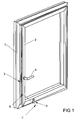
- FIG. 1 shows a window with a pivotable against a frame 1 wings 2 and with a drive rod fitting 3 for locking the wing 2 in the frame 1.
- a handle 4 for driving a blind guided in the wing 2 drive rod of the espagnolette 3 is arranged on the wing 2.
- the window has a display device 5, which holds the wing 2 in the illustrated, a gap far away from the frame 1 given position.
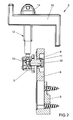
- FIG. 2 shows enlarged the Ausstellvorraum 5 from FIG. 1 in a sectional view along the line II - II.
- the display device 5 has a frame-side fitting part 6 and a wing-side fitting part 7.
- the frame-side fitting part 6 has a pivot arm 8 with a slot 9.
- the wing-side fitting part 7 has a guided in the slot 9 locking element 10 with a hook member 11 for engaging behind the swing arm. 8
- the locking element 10 can be connected via a lock 12 between an illustrated engagement position in which a positive connection is generated with the pivot arm 8, and a basic position in which the locking element 10 is pivoted back into the frame-side fitting part 6, drive.
- a gear 13 is arranged between the lock 12 and the locking element 10.
- the lock 12 can be driven by a key 14.
- the transmission 13 can also be driven by the displaceable by means of the handle 4 drive rod.
- a retaining plate 15 supports the lock on the wing.
- the frame-side fitting part 6 has a bearing 16 for the pivot arm 8 and a longitudinally displaceable fixing element 17 for the positive connection of the pivot arm 8 with the frame-side fitting part 6.
- the fixing element 17 is guided displaceably in a guide 18 on the bearing 16 and is in a retracted position in which the movement of the pivot arm 8 is released.
- the fixing member 17 can be with a projection 19 in a storage 16 facing away from the opening 20 of the swing arm 8 and thus block the movement of the swing arm 8.
- FIG. 3 shows that the swivel arm 8 has a recess 21 designed as a widening of the oblong hole 9 for insertion of the locking element 10.
- the locking element 10 can be inserted with the hook element 11 exclusively through the recess 21 in the slot 9.
- the pivot arm 8 is pivoted into the frame-side fitting part 6 and the in FIG. 1 shown wing 2 is in the frame. 1
- FIG. 4 shows a second perspective view of the display 5 in a view of the wing-side fitting part 7. It can be seen that in the slot 9, a stop member 22 is slidably disposed. The position of the stop element 22 can be detected, for example, by means of a not shown screening in the slot 9. As a result, the maximum distance of the locking element 10 in the slot 9 and thus the limit the maximum width in which the wing 2 can be pivoted away from the frame 1.
- the frame-side fitting part 6 and the wing-side fitting part 7 each have screw holes 23, 24 for screwing to the frame 1 or the wing second
Landscapes
- Engineering & Computer Science (AREA)
- Mechanical Engineering (AREA)
- Devices For Indicating Variable Information By Combining Individual Elements (AREA)
- Hinges (AREA)
Abstract
Description
- Die Erfindung betrifft eine Ausstellvorrichtung eines gegen einen Rahmen schwenkbaren Flügels, mit einem flügelseitigen Beschlagteil und einem rahmenseitigen Beschlagteil, mit einem in einen der Beschlagteile gelagerten und mit dem anderen Beschlagteil über ein Riegelelement verbindbaren Schwenkarm, wobei das Riegelelement zwischen einer Grundstellung, in der ein Formschluss mit dem Schwenkarm getrennt ist, in eine Eingriffsstellung, in der der Formschluss mit dem Schwenkarm erzeugt ist, antreibbar ist und der Schwenkarm bei in Eingriffsstellung befindlichem Riegelelement bei dem Öffnen des Flügels ausschwenkbar gelagert ist.
- Eine solche Ausstellvorrichtung ist beispielsweise aus der
DE 20 2005 000 634 U1 bekannt. Bei dieser Ausstellvorrichtung ermöglicht ein Arm eine gesicherte Stellung des Flügels in einer Offenstellung. Der Arm ist vorzugsweise am Rahmen gelagert. In eine Ausnehmung des Arms greift ein flügelseitiges Verriegelungselement ein. - Weiterhin ist aus der
EP 0 919 684 B1 ein Feststeller bekannt mit einem schwenkbaren Arm bekannt. Der Arm hat eine Lagerung auf einer mit dem Rahmen verschraubbaren Platine. Die Platine und der Arm haben Mittel, um den Arm in einer auf die Platine eingeschwenkten Position zu halten. Diese Mittel sind als einfache Anschläge ausgebildet, so dass der Arm jederzeit ausgeschwenkt werden kann. - Der Erfindung liegt das Problem zugrunde, eine Ausstellvorrichtung der eingangs genannten Art so weiter zu bilden, dass die Funktion der Begrenzung der Ausstellung des Flügels einfach aktivierbar und deaktivierbar ist.
- Dieses Problem wird erfindungsgemäß gelöst, durch ein Fixierelement zur formschlüssigen Verbindung des Schwenkarms mit dem eine Lagerung für den Schwenkarm aufweisenden Beschlagteil.
- Durch diese Gestaltung ermöglicht die Bewegung des Fixierelementes die wahlweise Freigabe oder Blockierung der Bewegung des Schwenkarms. Bei formschlüssig mit dem Schwenkarm verbundenen Fixierelement ist die Bewegung des Schwenkarms blockiert, und damit die Möglichkeit der Ausstellung des Flügels deaktiviert. Ein weiterer Vorteil der Ausstellvorrichtung besteht darin, dass diese die Möglichkeit eines separat ansteuerbaren Verschlusses ermöglicht. Ist der Schwenkarm gleichzeitig mit dem Riegelelement und dem Fixierelement verbunden, ermöglicht die Ausstellvorrichtung einen Verschluss des Flügels in dem Rahmen. Erst durch das Lösen des Formschlusses des Riegelelementes mit dem Schwenkarm kann der Flügel vollständig von dem Rahmen weggeschwenkt werden. Durch Lösen des Formschlusses des Fixierelementes mit dem Schwenkarm kann der Flügel in die vorgesehene Ausstellstellung gegenüber dem Flügel verschwenkt werden. Weiterhin lässt sich die Ausstellvorrichtung einfach bei bestehenden Fenstern, Fenstertüren oder dergleichen nachrüsten.
- Das Fixierelement vermag gemäß einer vorteilhaften Weiterbildung der Erfindung hohe Kräfte abzustützen, wenn das eine Beschlagteil eine Führung zur Verschiebung des Fixierelementes zwischen einer den Formschluss mit dem Schwenkarm erzeugenden Stellung und einer den Formschluss mit dem Schwenkarm lösenden Stellung hat.
- Die Ausstellvorrichtung gestaltet sich gemäß einer anderen vorteilhaften Weiterbildung der Erfindung konstruktiv besonders einfach, wenn die Führung auf die Lagerung hin gerichtet ist.
- Zur weiteren Vereinfachung des konstruktiven Aufbaus der Ausstellvorrichtung trägt es gemäß einer anderen vorteilhaften Weiterbildung der Erfindung bei, wenn das Fixierelement mit einem Vorsprung in eine der Lagerung abgewandten Öffnung des Schwenkarms einführbar ist.
- Zur weiteren Vereinfachung der Nutzung der Verriegelungsfunktion der Ausstellvorrichtung trägt es gemäß einer anderen vorteilhaften Weiterbildung der Erfindung bei, wenn das Riegelelement von einem Schloss zwischen der Grundstellung und der Eingriffsstellung antreibbar ist. Vorzugsweise ist das Schloss mit einem Schlüssel bedienbar.
- Ein zusätzlich zu montierendes Schloss lässt sich gemäß einer anderen vorteilhaften Weiterbildung der Erfindung einfach vermeiden, wenn die Bewegung des Riegelelementes mit einer Treibstange eines Treibstangenbeschlages gekoppelt ist. Durch diese Gestaltung ermöglicht die Ausstellvorrichtung eine Erzeugung einer Lüftungsstellung bei einer vorgesehenen Stellung der Treibstange.
- Das Riegelelement lässt sich gemäß einer anderen vorteilhaften Weiterbildung der Erfindung ausschließlich in der vorgesehenen Stellung mit dem Schwenkarm verbinden und lösen, wenn der Schwenkarm eine Ausnehmung zur Einführung des Riegelelementes hat und wenn das Riegelelement ein Hakenelement zur Hintergreifung des Schwenkarms in einer Position außerhalb der Ausnehmung hat. Vorzugsweise ist die Ausnehmung ausschließlich an einer Stelle des Schwenkarms angeordnet, die bei im Rahmen liegenden Flügel von dem Riegelelement zugänglich ist. Damit hintergreift das Hakenelement des Riegelelementes den Schwenkarm in der ausgestellten Stellung des Fensters. Diese Gestaltung bietet einen zusätzlichen Schutz gegen ein unberechtigtes Öffnen des Flügels.
- Die Ausstellvorrichtung gestaltet sich gemäß einer anderen vorteilhaften Weiterbildung der Erfindung konstruktiv besonders einfach, wenn der Schwenkarm ein Langloch zur Führung des Riegelelementes aufweist.
- Die Ausstellweite des Flügels lässt sich gemäß einer anderen vorteilhaften Weiterbildung der Erfindung einfach begrenzen, wenn ein Stoppelement in einer vorgesehenen Position in dem Langloch feststellbar ist.
- Die Ausstellweite lässt sich gemäß einer anderen vorteilhaften Weiterbildung der Erfindung in verschiedenen Abstufungen einstellen, wenn der Schwenkarm eine Rasterung für das Stoppelement aufweist. Dies trägt zur Erhöhung des Komforts bei der Bedienung der Ausstellvorrichtung bei.
- Die Erfindung lässt zahlreiche Ausführungsformen zu. Zur weiteren Verdeutlichung ihres Grundprinzips ist eine davon in der Zeichnung dargestellt und wird nachfolgend beschrieben. Diese zeigt in
- Fig. 1
- ein Fenster mit einer erfindungsgemäßen Ausstellvorrichtung,
- Fig. 2
- vergrößert eine Schnittdarstellung durch die Ausstellvorrichtung aus
Figur 1 , - Fig. 3
- eine erste perspektivische Darstellung auf die Ausstellvorrichtung,
- Fig. 4
- eine zweite perspektivische Darstellung auf die Ausstellvorrichtung.
-
Figur 1 zeigt ein Fenster mit einem gegen einen Rahmen 1 schwenkbaren Flügel 2 und mit einem Treibstangenbeschlag 3 zur Verriegelung des Flügels 2 in dem Rahmen 1. An dem Flügel 2 ist eine Handhabe 4 zum Antrieb einer verdeckt im Flügel 2 geführten Treibstange des Treibstangenbeschlages 3 angeordnet. Weiterhin hat das Fenster eine Ausstellvorrichtung 5, welche den Flügel 2 in der dargestellten, einen Spalt weit von dem Rahmen 1 weggeschenkten Stellung hält. -
Figur 2 zeigt vergrößert die Ausstellvorrichtung 5 ausFigur 1 in einer Schnittdarstellung entlang der Linie II - II. Zur Vereinfachung der Zeichnung sind Bauteile des Rahmens 1 und des Flügels 2 nicht dargestellt. Die Ausstellvorrichtung 5 hat ein rahmenseitiges Beschlagteil 6 und ein flügelseitiges Beschlagteil 7. Das rahmenseitige Beschlagteil 6 hat einen Schwenkarm 8 mit einem Langloch 9. Das flügelseitige Beschlagteil 7 hat ein in dem Langloch 9 geführtes Riegelelement 10 mit einem Hakenelement 11 zur Hintergreifung des Schwenkarms 8. Das Riegelelement 10 lässt sich über ein Schloss 12 zwischen einer dargestellten Eingriffsstellung, in der ein Formschluss mit dem Schwenkarm 8 erzeugt ist, und einer Grundstellung, in der das Riegelelement 10 in das rahmenseitige Beschlagteil 6 zurückgeschwenkt ist, antreiben. Hierzu ist zwischen dem Schloss 12 und dem Riegelelement 10 ein Getriebe 13 angeordnet. Das Schloss 12 lässt sich über einen Schlüssel 14 antreiben. In einer alternativen, nicht dargestellten Ausführungsform kann das Getriebe 13 auch von der mittels der Handhabe 4 verschieblichen Treibstange antreibbar sein. Eine Halteplatte 15 stützt das Schloss am Flügel ab. -
Figur 3 zeigt die Ausstellvorrichtung 5 in einer ersten perspektivischen Darstellung von oben auf das rahmenseitige Beschlagteil 6. Das rahmenseitige Beschlagteil 6 hat eine Lagerung 16 für den Schwenkarm 8 und ein längsverschiebliches Fixierelement 17 zur formschlüssigen Verbindung des Schwenkarms 8 mit dem rahmenseitigen Beschlagteil 6. Das Fixierelement 17 ist in einer Führung 18 auf die Lagerung 16 hin verschieblich geführt und befindet sich in einer zurückgezogenen Position, in der die Bewegung des Schwenkarms 8 freigegeben ist. Bei im rahmenseitigen Beschlagteil 6 eingeschwenkten Zustand des Schwenkarms 8 lässt sich das Fixierelement 17 mit einem Vorsprung 19 in eine der Lagerung 16 abgewandten Öffnung 20 des Schwenkarms 8 einführen und damit die Bewegung des Schwenkarms 8 blockieren. - Weiterhin zeigt
Figur 3 , dass der Schwenkarm 8 eine als Verbreiterung des Langlochs 9 ausgebildete Ausnehmung 21 zur Einführung des Riegelelementes 10 hat. Das Riegelelement 10 lässt sich mit dem Hakenelement 11 ausschließlich durch die Ausnehmung 21 in das Langloch 9 einführen. In der für das Riegelelement 10 zugänglichen Stellung der Ausnehmung 21 ist der Schwenkarm 8 in das rahmenseitige Beschlagteil 6 eingeschwenkt und der inFigur 1 dargestellte Flügel 2 liegt im Rahmen 1. -
Figur 4 zeigt eine zweite perspektivische Darstellung der Ausstellvorrichtung 5 in einer Ansicht auf das flügelseitige Beschlagteil 7. Hierbei ist zu erkennen, dass in dem Langloch 9 ein Stoppelement 22 verschieblich angeordnet ist. Die Position des Stoppelementes 22 ist beispielsweise mittels einer nicht dargestellten Rasterung in dem Langloch 9 feststellbar. Hierdurch lässt sich der maximale Weg des Riegelelementes 10 in dem Langloch 9 und damit die maximale Weite, in der der Flügel 2 von dem Rahmen 1 wegschwenkbar ist, begrenzen. - Das rahmenseitige Beschlagteil 6 und das flügelseitige Beschlagteil 7 haben jeweils Schraubbohrungen 23, 24 zur Verschraubung mit dem Rahmen 1 oder dem Flügel 2.
- Ausgehend von der in den
Figuren 1 bis 4 dargestellten Stellung der Ausstellvorrichtung 5 ist zum vollständigen Öffnen des Flügels 2 zunächst der Flügel 2 in den Rahmen 1 zu drücken. Anschließend kann über das Schloss 12 das Riegelelement 10 in die Grundstellung bewegt und damit von dem Schwenkarm 8 getrennt werden. Erst danach lässt sich der Flügel 2 von dem Rahmen 1 vollständig wegdrehen. Bei geöffnetem Flügel 2 ist das Fixierelement 17 zugänglich und kann mit dem Vorsprung 19 in die Öffnung 20 des Schwenkarms 8 eingeführt werden. Damit wird die Bewegung des Schwenkarms 8 blockiert. Wenn anschließend bei geschlossenem Flügel 2 das Riegelelement 10 über das Schloss 12 in die Eingriffsstellung angetrieben wird, ist ein Formschluss zwischen Riegelelement 10 und Schwenkarm 8 und damit zwischen dem rahmenseitigen Beschlagteil 6 und dem flügelseitigem Beschlagteil 7 erzeugt. Damit ist der Flügel 2 unabhängig von der Stellung der Handhabe 4 und des Treibstangenbeschlages 3 in dem Rahmen 1 verriegelt.
Claims (10)
- Ausstellvorrichtung (5) eines gegen einen Rahmen (1) schwenkbaren Flügels (2), mit einem flügelseitigen Beschlagteil (7) und einem rahmenseitigen Beschlagteil (6), mit einem in einen der Beschlagteile (6, 7) gelagerten und mit dem anderen Beschlagteil (7, 6) über ein Riegelelement (10) verbindbaren Schwenkarm (8), wobei das Riegelelement (10) zwischen einer Grundstellung, in der ein Formschluss mit dem Schwenkarm (8) getrennt ist, in eine Eingriffsstellung, in der der Formschluss mit dem Schwenkarm (8) erzeugt ist, antreibbar ist und der Schwenkarm (8) bei in Eingriffsstellung befindlichem Riegelelement (10) bei dem Öffnen des Flügels (2) ausschwenkbar gelagert ist, gekennzeichnet durch ein Fixierelement (17) zur formschlüssigen Verbindung des Schwenkarms (8) mit dem eine Lagerung (16) für den Schwenkarm (8) aufweisenden Beschlagteil (6).
- Ausstellvorrichtung nach Anspruch 1, dadurch gekennzeichnet, dass das eine Beschlagteil (6) eine Führung (18) zur Verschiebung des Fixierelementes (17) zwischen einer den Formschluss mit dem Schwenkarm (8) erzeugenden Stellung und einer den Formschluss mit dem Schwenkarm (8) lösenden Stellung hat.
- Ausstellvorrichtung nach Anspruch 2, dadurch gekennzeichnet, dass die Führung (18) auf die Lagerung (16) hin gerichtet ist.
- Ausstellvorrichtung nach einem der vorhergehenden Ansprüche, dadurch gekennzeichnet, dass das Fixierelement (17) mit einem Vorsprung (19) in eine der Lagerung (16) abgewandte Öffnung (20) des Schwenkarms (8) einführbar ist.
- Ausstellvorrichtung nach einem der vorhergehenden Ansprüche, dadurch gekennzeichnet, dass das Riegelelement (10) von einem Schloss (12) zwischen der Grundstellung und der Eingriffsstellung antreibbar ist.
- Ausstellvorrichtung nach einem der vorhergehenden Ansprüche, dadurch gekennzeichnet, dass die Bewegung des Riegelelementes (10) mit einer Treibstange eines Treibstangenbeschlages (3) gekoppelt ist.
- Ausstellvorrichtung nach einem der vorhergehenden Ansprüche, dadurch gekennzeichnet, dass der Schwenkarm (8) eine Ausnehmung (21) zur Einführung des Riegelelementes (10) hat und dass das Riegelelement (10) ein Hakenelement (11) zur Hintergreifung des Schwenkarms (8) in einer Position außerhalb der Ausnehmung (21) hat.
- Ausstellvorrichtung nach einem der vorhergehenden Ansprüche, dadurch gekennzeichnet, dass der Schwenkarm (8) ein Langloch (9) zur Führung des Riegelelementes (10) aufweist
- Ausstellvorrichtung nach Anspruch 8, dadurch gekennzeichnet, dass ein Stoppelement (22) in einer vorgesehenen Position in dem Langloch (9) feststellbar ist.
- Ausstellvorrichtung nach Anspruch 9, dadurch gekennzeichnet, dass der Schwenkarm (8) eine Rasterung für das Stoppelement (22) aufweist.
Priority Applications (1)
| Application Number | Priority Date | Filing Date | Title |
|---|---|---|---|
| PL16184194T PL3141681T3 (pl) | 2015-09-14 | 2016-08-15 | Urządzenie wychylające skrzydła uchylnego w stosunku do ramy |
Applications Claiming Priority (1)
| Application Number | Priority Date | Filing Date | Title |
|---|---|---|---|
| DE102015217539.1A DE102015217539A1 (de) | 2015-09-14 | 2015-09-14 | Ausstellvorrichtung eines gegen einen Rahmen schwenkbaren Flügels |
Publications (2)
| Publication Number | Publication Date |
|---|---|
| EP3141681A1 true EP3141681A1 (de) | 2017-03-15 |
| EP3141681B1 EP3141681B1 (de) | 2018-10-17 |
Family
ID=56737959
Family Applications (1)
| Application Number | Title | Priority Date | Filing Date |
|---|---|---|---|
| EP16184194.5A Active EP3141681B1 (de) | 2015-09-14 | 2016-08-15 | Ausstellvorrichtung eines gegen einen rahmen schwenkbaren flügels |
Country Status (3)
| Country | Link |
|---|---|
| EP (1) | EP3141681B1 (de) |
| DE (1) | DE102015217539A1 (de) |
| PL (1) | PL3141681T3 (de) |
Families Citing this family (1)
| Publication number | Priority date | Publication date | Assignee | Title |
|---|---|---|---|---|
| AT524565B1 (de) * | 2020-12-18 | 2022-07-15 | Siemens Mobility Austria Gmbh | Türspaltsperre |
Citations (9)
| Publication number | Priority date | Publication date | Assignee | Title |
|---|---|---|---|---|
| DE44038C (de) * | FR. WAMSLER, Königl. Hoflieferant in München, Schellingstr. 73 | Automatischer Sicherheitsverschlufs für Thüren | ||
| US741674A (en) * | 1903-01-13 | 1903-10-20 | Adam Kalb | Combined door check and lock. |
| US1684790A (en) * | 1927-07-23 | 1928-09-18 | Ajax Brand Lock Corp | Safety door fastener |
| GB727588A (en) * | 1952-05-06 | 1955-04-06 | Stuart Edward Grand | Improvements in and relating to stays for doors and windows |
| DE4409393A1 (de) * | 1994-03-18 | 1995-09-21 | Winkhaus Fa August | Einrichtung zur Feststellung eines Flügelrahmens an einem Blendrahmen in einer Spaltöffnungsstellung |
| GB2288433A (en) * | 1994-04-16 | 1995-10-18 | Banks J & Co Ltd | Door or window stay |
| GB2346923A (en) * | 1998-10-27 | 2000-08-23 | Chris Hamer | Security device |
| EP0919684B1 (de) | 1997-11-28 | 2002-09-18 | Ferco International Ferrures et Serrures de Bâtiment | Feststeller |
| DE202005000634U1 (de) | 2005-01-15 | 2005-03-24 | Winkhaus Fa August | Feststellvorrichtung für Fenster oder Türen |
-
2015
- 2015-09-14 DE DE102015217539.1A patent/DE102015217539A1/de not_active Withdrawn
-
2016
- 2016-08-15 EP EP16184194.5A patent/EP3141681B1/de active Active
- 2016-08-15 PL PL16184194T patent/PL3141681T3/pl unknown
Patent Citations (9)
| Publication number | Priority date | Publication date | Assignee | Title |
|---|---|---|---|---|
| DE44038C (de) * | FR. WAMSLER, Königl. Hoflieferant in München, Schellingstr. 73 | Automatischer Sicherheitsverschlufs für Thüren | ||
| US741674A (en) * | 1903-01-13 | 1903-10-20 | Adam Kalb | Combined door check and lock. |
| US1684790A (en) * | 1927-07-23 | 1928-09-18 | Ajax Brand Lock Corp | Safety door fastener |
| GB727588A (en) * | 1952-05-06 | 1955-04-06 | Stuart Edward Grand | Improvements in and relating to stays for doors and windows |
| DE4409393A1 (de) * | 1994-03-18 | 1995-09-21 | Winkhaus Fa August | Einrichtung zur Feststellung eines Flügelrahmens an einem Blendrahmen in einer Spaltöffnungsstellung |
| GB2288433A (en) * | 1994-04-16 | 1995-10-18 | Banks J & Co Ltd | Door or window stay |
| EP0919684B1 (de) | 1997-11-28 | 2002-09-18 | Ferco International Ferrures et Serrures de Bâtiment | Feststeller |
| GB2346923A (en) * | 1998-10-27 | 2000-08-23 | Chris Hamer | Security device |
| DE202005000634U1 (de) | 2005-01-15 | 2005-03-24 | Winkhaus Fa August | Feststellvorrichtung für Fenster oder Türen |
Also Published As
| Publication number | Publication date |
|---|---|
| DE102015217539A1 (de) | 2017-03-16 |
| PL3141681T3 (pl) | 2019-04-30 |
| EP3141681B1 (de) | 2018-10-17 |
Similar Documents
| Publication | Publication Date | Title |
|---|---|---|
| EP3102759B1 (de) | Beschlag eines zumindest hebbaren und verschiebbaren flügels von fenstern oder türen | |
| EP1978193B1 (de) | Drehöffnungsbegrenzung für einen Dreh-Flügel eines Fensters, einer Tür oder dergleichen | |
| EP3622139A1 (de) | Fenster oder tür mit einbruchsicherer kippöffnungsbegrenzung | |
| EP2853666B1 (de) | Verschluss für einen Treibstangenbeschlag | |
| DE19725677A1 (de) | Fenster, Tür od. dgl. an Wohnwagen, Wohnmobilen oder sonstigen Fahrzeugen | |
| EP3141681B1 (de) | Ausstellvorrichtung eines gegen einen rahmen schwenkbaren flügels | |
| DE102008007095B4 (de) | Dreh-Kipp-Beschlag | |
| EP2149661B1 (de) | Gebäudeabschluss in sprengwirkungshemmender und/oder einbruchhemmender Ausführung | |
| EP3371397B1 (de) | Beschlaganordnung | |
| EP3018269B1 (de) | Griffanordnung für ein fenster oder dergleichen sowie fenster oder dergleichen mit griffanordnung | |
| DE10015095C2 (de) | Verriegelungsvorrichtung für einen Türflügel | |
| AT509464B1 (de) | Schloss | |
| EP1965010B1 (de) | Antriebsvorrichtung | |
| EP3235988A1 (de) | Fenstersystem und/oder türsystem | |
| DE102005002296B3 (de) | Fenster, Tür oder dergleichen sowie Treibstangenbeschlag mit einem Verriegelungs-Schwenkelement | |
| EP2620572B1 (de) | Sperreinrichtung zur sperrung einer bewegung eines gegen einen rahmen bewegbaren flügels | |
| DE102014111131A1 (de) | Vorrichtung zur Ver- und Entriegelung eines Fensterflügels, einer Lüftungsklappe oder dergleichen an einem Blendrahmen | |
| DE102015206908A1 (de) | Fenster, Tür oder dergleichen mit einem Beschlag | |
| EP4215704B1 (de) | Sperrvorrichtung, beschlag und flügel-rahmenanordnung | |
| DE602005004110T2 (de) | Verriegelungsmechanismus und Teile dafür | |
| EP2216470B1 (de) | Verschluss für einen Treibstangenbeschlag | |
| EP2530226A2 (de) | Verschluss eines Treibstangenbeschlages | |
| EP3498943B1 (de) | Schloss | |
| EP3279419B1 (de) | Ausstellschere für einen treibstangenbeschlag | |
| DE102022117895A1 (de) | Beschlaganordnung zum verriegeln eines verschiebbaren flügels |
Legal Events
| Date | Code | Title | Description |
|---|---|---|---|
| PUAI | Public reference made under article 153(3) epc to a published international application that has entered the european phase |
Free format text: ORIGINAL CODE: 0009012 |
|
| STAA | Information on the status of an ep patent application or granted ep patent |
Free format text: STATUS: THE APPLICATION HAS BEEN PUBLISHED |
|
| AK | Designated contracting states |
Kind code of ref document: A1 Designated state(s): AL AT BE BG CH CY CZ DE DK EE ES FI FR GB GR HR HU IE IS IT LI LT LU LV MC MK MT NL NO PL PT RO RS SE SI SK SM TR |
|
| AX | Request for extension of the european patent |
Extension state: BA ME |
|
| STAA | Information on the status of an ep patent application or granted ep patent |
Free format text: STATUS: REQUEST FOR EXAMINATION WAS MADE |
|
| 17P | Request for examination filed |
Effective date: 20170815 |
|
| RBV | Designated contracting states (corrected) |
Designated state(s): AL AT BE BG CH CY CZ DE DK EE ES FI FR GB GR HR HU IE IS IT LI LT LU LV MC MK MT NL NO PL PT RO RS SE SI SK SM TR |
|
| GRAP | Despatch of communication of intention to grant a patent |
Free format text: ORIGINAL CODE: EPIDOSNIGR1 |
|
| STAA | Information on the status of an ep patent application or granted ep patent |
Free format text: STATUS: GRANT OF PATENT IS INTENDED |
|
| RIC1 | Information provided on ipc code assigned before grant |
Ipc: E05C 17/16 20060101AFI20180326BHEP Ipc: E05C 9/18 20060101ALI20180326BHEP |
|
| INTG | Intention to grant announced |
Effective date: 20180426 |
|
| GRAS | Grant fee paid |
Free format text: ORIGINAL CODE: EPIDOSNIGR3 |
|
| GRAA | (expected) grant |
Free format text: ORIGINAL CODE: 0009210 |
|
| STAA | Information on the status of an ep patent application or granted ep patent |
Free format text: STATUS: THE PATENT HAS BEEN GRANTED |
|
| AK | Designated contracting states |
Kind code of ref document: B1 Designated state(s): AL AT BE BG CH CY CZ DE DK EE ES FI FR GB GR HR HU IE IS IT LI LT LU LV MC MK MT NL NO PL PT RO RS SE SI SK SM TR |
|
| REG | Reference to a national code |
Ref country code: GB Ref legal event code: FG4D Free format text: NOT ENGLISH |
|
| REG | Reference to a national code |
Ref country code: CH Ref legal event code: EP |
|
| REG | Reference to a national code |
Ref country code: IE Ref legal event code: FG4D Free format text: LANGUAGE OF EP DOCUMENT: GERMAN |
|
| REG | Reference to a national code |
Ref country code: DE Ref legal event code: R096 Ref document number: 502016002240 Country of ref document: DE Ref country code: AT Ref legal event code: REF Ref document number: 1054227 Country of ref document: AT Kind code of ref document: T Effective date: 20181115 |
|
| REG | Reference to a national code |
Ref country code: NL Ref legal event code: MP Effective date: 20181017 |
|
| REG | Reference to a national code |
Ref country code: LT Ref legal event code: MG4D |
|
| PG25 | Lapsed in a contracting state [announced via postgrant information from national office to epo] |
Ref country code: NL Free format text: LAPSE BECAUSE OF FAILURE TO SUBMIT A TRANSLATION OF THE DESCRIPTION OR TO PAY THE FEE WITHIN THE PRESCRIBED TIME-LIMIT Effective date: 20181017 |
|
| PG25 | Lapsed in a contracting state [announced via postgrant information from national office to epo] |
Ref country code: FI Free format text: LAPSE BECAUSE OF FAILURE TO SUBMIT A TRANSLATION OF THE DESCRIPTION OR TO PAY THE FEE WITHIN THE PRESCRIBED TIME-LIMIT Effective date: 20181017 Ref country code: LV Free format text: LAPSE BECAUSE OF FAILURE TO SUBMIT A TRANSLATION OF THE DESCRIPTION OR TO PAY THE FEE WITHIN THE PRESCRIBED TIME-LIMIT Effective date: 20181017 Ref country code: HR Free format text: LAPSE BECAUSE OF FAILURE TO SUBMIT A TRANSLATION OF THE DESCRIPTION OR TO PAY THE FEE WITHIN THE PRESCRIBED TIME-LIMIT Effective date: 20181017 Ref country code: BG Free format text: LAPSE BECAUSE OF FAILURE TO SUBMIT A TRANSLATION OF THE DESCRIPTION OR TO PAY THE FEE WITHIN THE PRESCRIBED TIME-LIMIT Effective date: 20190117 Ref country code: ES Free format text: LAPSE BECAUSE OF FAILURE TO SUBMIT A TRANSLATION OF THE DESCRIPTION OR TO PAY THE FEE WITHIN THE PRESCRIBED TIME-LIMIT Effective date: 20181017 Ref country code: LT Free format text: LAPSE BECAUSE OF FAILURE TO SUBMIT A TRANSLATION OF THE DESCRIPTION OR TO PAY THE FEE WITHIN THE PRESCRIBED TIME-LIMIT Effective date: 20181017 Ref country code: NO Free format text: LAPSE BECAUSE OF FAILURE TO SUBMIT A TRANSLATION OF THE DESCRIPTION OR TO PAY THE FEE WITHIN THE PRESCRIBED TIME-LIMIT Effective date: 20190117 Ref country code: IS Free format text: LAPSE BECAUSE OF FAILURE TO SUBMIT A TRANSLATION OF THE DESCRIPTION OR TO PAY THE FEE WITHIN THE PRESCRIBED TIME-LIMIT Effective date: 20190217 |
|
| PG25 | Lapsed in a contracting state [announced via postgrant information from national office to epo] |
Ref country code: PT Free format text: LAPSE BECAUSE OF FAILURE TO SUBMIT A TRANSLATION OF THE DESCRIPTION OR TO PAY THE FEE WITHIN THE PRESCRIBED TIME-LIMIT Effective date: 20190217 Ref country code: GR Free format text: LAPSE BECAUSE OF FAILURE TO SUBMIT A TRANSLATION OF THE DESCRIPTION OR TO PAY THE FEE WITHIN THE PRESCRIBED TIME-LIMIT Effective date: 20190118 Ref country code: RS Free format text: LAPSE BECAUSE OF FAILURE TO SUBMIT A TRANSLATION OF THE DESCRIPTION OR TO PAY THE FEE WITHIN THE PRESCRIBED TIME-LIMIT Effective date: 20181017 Ref country code: AL Free format text: LAPSE BECAUSE OF FAILURE TO SUBMIT A TRANSLATION OF THE DESCRIPTION OR TO PAY THE FEE WITHIN THE PRESCRIBED TIME-LIMIT Effective date: 20181017 Ref country code: SE Free format text: LAPSE BECAUSE OF FAILURE TO SUBMIT A TRANSLATION OF THE DESCRIPTION OR TO PAY THE FEE WITHIN THE PRESCRIBED TIME-LIMIT Effective date: 20181017 |
|
| REG | Reference to a national code |
Ref country code: DE Ref legal event code: R097 Ref document number: 502016002240 Country of ref document: DE |
|
| PG25 | Lapsed in a contracting state [announced via postgrant information from national office to epo] |
Ref country code: CZ Free format text: LAPSE BECAUSE OF FAILURE TO SUBMIT A TRANSLATION OF THE DESCRIPTION OR TO PAY THE FEE WITHIN THE PRESCRIBED TIME-LIMIT Effective date: 20181017 Ref country code: IT Free format text: LAPSE BECAUSE OF FAILURE TO SUBMIT A TRANSLATION OF THE DESCRIPTION OR TO PAY THE FEE WITHIN THE PRESCRIBED TIME-LIMIT Effective date: 20181017 Ref country code: DK Free format text: LAPSE BECAUSE OF FAILURE TO SUBMIT A TRANSLATION OF THE DESCRIPTION OR TO PAY THE FEE WITHIN THE PRESCRIBED TIME-LIMIT Effective date: 20181017 |
|
| PLBE | No opposition filed within time limit |
Free format text: ORIGINAL CODE: 0009261 |
|
| STAA | Information on the status of an ep patent application or granted ep patent |
Free format text: STATUS: NO OPPOSITION FILED WITHIN TIME LIMIT |
|
| PG25 | Lapsed in a contracting state [announced via postgrant information from national office to epo] |
Ref country code: EE Free format text: LAPSE BECAUSE OF FAILURE TO SUBMIT A TRANSLATION OF THE DESCRIPTION OR TO PAY THE FEE WITHIN THE PRESCRIBED TIME-LIMIT Effective date: 20181017 Ref country code: SM Free format text: LAPSE BECAUSE OF FAILURE TO SUBMIT A TRANSLATION OF THE DESCRIPTION OR TO PAY THE FEE WITHIN THE PRESCRIBED TIME-LIMIT Effective date: 20181017 Ref country code: SK Free format text: LAPSE BECAUSE OF FAILURE TO SUBMIT A TRANSLATION OF THE DESCRIPTION OR TO PAY THE FEE WITHIN THE PRESCRIBED TIME-LIMIT Effective date: 20181017 Ref country code: RO Free format text: LAPSE BECAUSE OF FAILURE TO SUBMIT A TRANSLATION OF THE DESCRIPTION OR TO PAY THE FEE WITHIN THE PRESCRIBED TIME-LIMIT Effective date: 20181017 |
|
| 26N | No opposition filed |
Effective date: 20190718 |
|
| PG25 | Lapsed in a contracting state [announced via postgrant information from national office to epo] |
Ref country code: SI Free format text: LAPSE BECAUSE OF FAILURE TO SUBMIT A TRANSLATION OF THE DESCRIPTION OR TO PAY THE FEE WITHIN THE PRESCRIBED TIME-LIMIT Effective date: 20181017 |
|
| PG25 | Lapsed in a contracting state [announced via postgrant information from national office to epo] |
Ref country code: TR Free format text: LAPSE BECAUSE OF FAILURE TO SUBMIT A TRANSLATION OF THE DESCRIPTION OR TO PAY THE FEE WITHIN THE PRESCRIBED TIME-LIMIT Effective date: 20181017 |
|
| PG25 | Lapsed in a contracting state [announced via postgrant information from national office to epo] |
Ref country code: LI Free format text: LAPSE BECAUSE OF NON-PAYMENT OF DUE FEES Effective date: 20190831 Ref country code: MC Free format text: LAPSE BECAUSE OF FAILURE TO SUBMIT A TRANSLATION OF THE DESCRIPTION OR TO PAY THE FEE WITHIN THE PRESCRIBED TIME-LIMIT Effective date: 20181017 Ref country code: CH Free format text: LAPSE BECAUSE OF NON-PAYMENT OF DUE FEES Effective date: 20190831 Ref country code: LU Free format text: LAPSE BECAUSE OF NON-PAYMENT OF DUE FEES Effective date: 20190815 |
|
| REG | Reference to a national code |
Ref country code: BE Ref legal event code: MM Effective date: 20190831 |
|
| PG25 | Lapsed in a contracting state [announced via postgrant information from national office to epo] |
Ref country code: IE Free format text: LAPSE BECAUSE OF NON-PAYMENT OF DUE FEES Effective date: 20190815 |
|
| PG25 | Lapsed in a contracting state [announced via postgrant information from national office to epo] |
Ref country code: BE Free format text: LAPSE BECAUSE OF NON-PAYMENT OF DUE FEES Effective date: 20190831 |
|
| GBPC | Gb: european patent ceased through non-payment of renewal fee |
Effective date: 20200815 |
|
| PG25 | Lapsed in a contracting state [announced via postgrant information from national office to epo] |
Ref country code: CY Free format text: LAPSE BECAUSE OF FAILURE TO SUBMIT A TRANSLATION OF THE DESCRIPTION OR TO PAY THE FEE WITHIN THE PRESCRIBED TIME-LIMIT Effective date: 20181017 |
|
| PG25 | Lapsed in a contracting state [announced via postgrant information from national office to epo] |
Ref country code: HU Free format text: LAPSE BECAUSE OF FAILURE TO SUBMIT A TRANSLATION OF THE DESCRIPTION OR TO PAY THE FEE WITHIN THE PRESCRIBED TIME-LIMIT; INVALID AB INITIO Effective date: 20160815 Ref country code: MT Free format text: LAPSE BECAUSE OF FAILURE TO SUBMIT A TRANSLATION OF THE DESCRIPTION OR TO PAY THE FEE WITHIN THE PRESCRIBED TIME-LIMIT Effective date: 20181017 |
|
| PG25 | Lapsed in a contracting state [announced via postgrant information from national office to epo] |
Ref country code: GB Free format text: LAPSE BECAUSE OF NON-PAYMENT OF DUE FEES Effective date: 20200815 |
|
| PG25 | Lapsed in a contracting state [announced via postgrant information from national office to epo] |
Ref country code: MK Free format text: LAPSE BECAUSE OF FAILURE TO SUBMIT A TRANSLATION OF THE DESCRIPTION OR TO PAY THE FEE WITHIN THE PRESCRIBED TIME-LIMIT Effective date: 20181017 |
|
| P01 | Opt-out of the competence of the unified patent court (upc) registered |
Effective date: 20230515 |
|
| PGFP | Annual fee paid to national office [announced via postgrant information from national office to epo] |
Ref country code: FR Payment date: 20240823 Year of fee payment: 9 |
|
| PGFP | Annual fee paid to national office [announced via postgrant information from national office to epo] |
Ref country code: PL Payment date: 20240807 Year of fee payment: 9 |
|
| REG | Reference to a national code |
Ref country code: DE Ref legal event code: R081 Ref document number: 502016002240 Country of ref document: DE Owner name: AUG. WINKHAUS SE & CO. KG, DE Free format text: FORMER OWNER: AUG. WINKHAUS GMBH & CO. KG, 48291 TELGTE, DE Ref country code: DE Ref legal event code: R081 Ref document number: 502016002240 Country of ref document: DE Owner name: AUG. WINKHAUS SE, DE Free format text: FORMER OWNER: AUG. WINKHAUS GMBH & CO. KG, 48291 TELGTE, DE |
|
| REG | Reference to a national code |
Ref country code: DE Ref legal event code: R081 Ref document number: 502016002240 Country of ref document: DE Owner name: AUG. WINKHAUS SE, DE Free format text: FORMER OWNER: AUG. WINKHAUS SE & CO. KG, 48291 TELGTE, DE |
|
| PGFP | Annual fee paid to national office [announced via postgrant information from national office to epo] |
Ref country code: DE Payment date: 20250819 Year of fee payment: 10 |
|
| PGFP | Annual fee paid to national office [announced via postgrant information from national office to epo] |
Ref country code: AT Payment date: 20250819 Year of fee payment: 10 |