EP3141417A2 - Chargeurs pour véhicules électriques - Google Patents
Chargeurs pour véhicules électriques Download PDFInfo
- Publication number
- EP3141417A2 EP3141417A2 EP16191966.7A EP16191966A EP3141417A2 EP 3141417 A2 EP3141417 A2 EP 3141417A2 EP 16191966 A EP16191966 A EP 16191966A EP 3141417 A2 EP3141417 A2 EP 3141417A2
- Authority
- EP
- European Patent Office
- Prior art keywords
- charging
- charge
- contact
- vehicle
- bus
- Prior art date
- Legal status (The legal status is an assumption and is not a legal conclusion. Google has not performed a legal analysis and makes no representation as to the accuracy of the status listed.)
- Granted
Links
- 238000004146 energy storage Methods 0.000 claims description 14
- 238000000034 method Methods 0.000 abstract description 23
- 230000000712 assembly Effects 0.000 description 45
- 238000000429 assembly Methods 0.000 description 45
- 230000008878 coupling Effects 0.000 description 16
- 238000010168 coupling process Methods 0.000 description 16
- 238000005859 coupling reaction Methods 0.000 description 16
- 239000004020 conductor Substances 0.000 description 8
- 239000000463 material Substances 0.000 description 8
- 238000012546 transfer Methods 0.000 description 7
- RYGMFSIKBFXOCR-UHFFFAOYSA-N Copper Chemical compound [Cu] RYGMFSIKBFXOCR-UHFFFAOYSA-N 0.000 description 6
- 229910052802 copper Inorganic materials 0.000 description 6
- 239000010949 copper Substances 0.000 description 6
- 230000007246 mechanism Effects 0.000 description 5
- 238000005303 weighing Methods 0.000 description 5
- 239000003990 capacitor Substances 0.000 description 4
- 238000004891 communication Methods 0.000 description 4
- 238000012986 modification Methods 0.000 description 4
- 230000004048 modification Effects 0.000 description 4
- OKTJSMMVPCPJKN-UHFFFAOYSA-N Carbon Chemical compound [C] OKTJSMMVPCPJKN-UHFFFAOYSA-N 0.000 description 3
- BQCADISMDOOEFD-UHFFFAOYSA-N Silver Chemical compound [Ag] BQCADISMDOOEFD-UHFFFAOYSA-N 0.000 description 3
- 229910045601 alloy Inorganic materials 0.000 description 3
- 239000000956 alloy Substances 0.000 description 3
- 229910052782 aluminium Inorganic materials 0.000 description 3
- XAGFODPZIPBFFR-UHFFFAOYSA-N aluminium Chemical compound [Al] XAGFODPZIPBFFR-UHFFFAOYSA-N 0.000 description 3
- 230000008901 benefit Effects 0.000 description 3
- 229910052799 carbon Inorganic materials 0.000 description 3
- 238000009429 electrical wiring Methods 0.000 description 3
- PCHJSUWPFVWCPO-UHFFFAOYSA-N gold Chemical compound [Au] PCHJSUWPFVWCPO-UHFFFAOYSA-N 0.000 description 3
- 229910052737 gold Inorganic materials 0.000 description 3
- 239000010931 gold Substances 0.000 description 3
- 230000005484 gravity Effects 0.000 description 3
- 238000012544 monitoring process Methods 0.000 description 3
- 229910052709 silver Inorganic materials 0.000 description 3
- 239000004332 silver Substances 0.000 description 3
- WHXSMMKQMYFTQS-UHFFFAOYSA-N Lithium Chemical compound [Li] WHXSMMKQMYFTQS-UHFFFAOYSA-N 0.000 description 2
- RTAQQCXQSZGOHL-UHFFFAOYSA-N Titanium Chemical compound [Ti] RTAQQCXQSZGOHL-UHFFFAOYSA-N 0.000 description 2
- 238000010438 heat treatment Methods 0.000 description 2
- 229910052744 lithium Inorganic materials 0.000 description 2
- 238000004137 mechanical activation Methods 0.000 description 2
- 230000001681 protective effect Effects 0.000 description 2
- 239000004677 Nylon Substances 0.000 description 1
- 238000013459 approach Methods 0.000 description 1
- 238000012512 characterization method Methods 0.000 description 1
- 238000004140 cleaning Methods 0.000 description 1
- 239000011248 coating agent Substances 0.000 description 1
- 238000000576 coating method Methods 0.000 description 1
- 238000010276 construction Methods 0.000 description 1
- 230000007797 corrosion Effects 0.000 description 1
- 238000005260 corrosion Methods 0.000 description 1
- 238000013461 design Methods 0.000 description 1
- 238000001514 detection method Methods 0.000 description 1
- 230000005611 electricity Effects 0.000 description 1
- 239000000446 fuel Substances 0.000 description 1
- 229910052739 hydrogen Inorganic materials 0.000 description 1
- 239000001257 hydrogen Substances 0.000 description 1
- 125000004435 hydrogen atom Chemical class [H]* 0.000 description 1
- 238000010348 incorporation Methods 0.000 description 1
- 238000012423 maintenance Methods 0.000 description 1
- 229910052751 metal Inorganic materials 0.000 description 1
- 239000002184 metal Substances 0.000 description 1
- 229910001092 metal group alloy Inorganic materials 0.000 description 1
- 150000002739 metals Chemical class 0.000 description 1
- 238000012806 monitoring device Methods 0.000 description 1
- 229920001778 nylon Polymers 0.000 description 1
- 239000004033 plastic Substances 0.000 description 1
- 229920000642 polymer Polymers 0.000 description 1
- 230000003252 repetitive effect Effects 0.000 description 1
- 238000011160 research Methods 0.000 description 1
- 230000002269 spontaneous effect Effects 0.000 description 1
- XLYOFNOQVPJJNP-UHFFFAOYSA-N water Substances O XLYOFNOQVPJJNP-UHFFFAOYSA-N 0.000 description 1
Images


Classifications
-
- B—PERFORMING OPERATIONS; TRANSPORTING
- B60—VEHICLES IN GENERAL
- B60L—PROPULSION OF ELECTRICALLY-PROPELLED VEHICLES; SUPPLYING ELECTRIC POWER FOR AUXILIARY EQUIPMENT OF ELECTRICALLY-PROPELLED VEHICLES; ELECTRODYNAMIC BRAKE SYSTEMS FOR VEHICLES IN GENERAL; MAGNETIC SUSPENSION OR LEVITATION FOR VEHICLES; MONITORING OPERATING VARIABLES OF ELECTRICALLY-PROPELLED VEHICLES; ELECTRIC SAFETY DEVICES FOR ELECTRICALLY-PROPELLED VEHICLES
- B60L53/00—Methods of charging batteries, specially adapted for electric vehicles; Charging stations or on-board charging equipment therefor; Exchange of energy storage elements in electric vehicles
- B60L53/10—Methods of charging batteries, specially adapted for electric vehicles; Charging stations or on-board charging equipment therefor; Exchange of energy storage elements in electric vehicles characterised by the energy transfer between the charging station and the vehicle
- B60L53/14—Conductive energy transfer
-
- B—PERFORMING OPERATIONS; TRANSPORTING
- B60—VEHICLES IN GENERAL
- B60L—PROPULSION OF ELECTRICALLY-PROPELLED VEHICLES; SUPPLYING ELECTRIC POWER FOR AUXILIARY EQUIPMENT OF ELECTRICALLY-PROPELLED VEHICLES; ELECTRODYNAMIC BRAKE SYSTEMS FOR VEHICLES IN GENERAL; MAGNETIC SUSPENSION OR LEVITATION FOR VEHICLES; MONITORING OPERATING VARIABLES OF ELECTRICALLY-PROPELLED VEHICLES; ELECTRIC SAFETY DEVICES FOR ELECTRICALLY-PROPELLED VEHICLES
- B60L50/00—Electric propulsion with power supplied within the vehicle
- B60L50/50—Electric propulsion with power supplied within the vehicle using propulsion power supplied by batteries or fuel cells
-
- B—PERFORMING OPERATIONS; TRANSPORTING
- B60—VEHICLES IN GENERAL
- B60L—PROPULSION OF ELECTRICALLY-PROPELLED VEHICLES; SUPPLYING ELECTRIC POWER FOR AUXILIARY EQUIPMENT OF ELECTRICALLY-PROPELLED VEHICLES; ELECTRODYNAMIC BRAKE SYSTEMS FOR VEHICLES IN GENERAL; MAGNETIC SUSPENSION OR LEVITATION FOR VEHICLES; MONITORING OPERATING VARIABLES OF ELECTRICALLY-PROPELLED VEHICLES; ELECTRIC SAFETY DEVICES FOR ELECTRICALLY-PROPELLED VEHICLES
- B60L5/00—Current collectors for power supply lines of electrically-propelled vehicles
- B60L5/005—Current collectors for power supply lines of electrically-propelled vehicles without mechanical contact between the collector and the power supply line
-
- B—PERFORMING OPERATIONS; TRANSPORTING
- B60—VEHICLES IN GENERAL
- B60L—PROPULSION OF ELECTRICALLY-PROPELLED VEHICLES; SUPPLYING ELECTRIC POWER FOR AUXILIARY EQUIPMENT OF ELECTRICALLY-PROPELLED VEHICLES; ELECTRODYNAMIC BRAKE SYSTEMS FOR VEHICLES IN GENERAL; MAGNETIC SUSPENSION OR LEVITATION FOR VEHICLES; MONITORING OPERATING VARIABLES OF ELECTRICALLY-PROPELLED VEHICLES; ELECTRIC SAFETY DEVICES FOR ELECTRICALLY-PROPELLED VEHICLES
- B60L5/00—Current collectors for power supply lines of electrically-propelled vehicles
- B60L5/42—Current collectors for power supply lines of electrically-propelled vehicles for collecting current from individual contact pieces connected to the power supply line
-
- B—PERFORMING OPERATIONS; TRANSPORTING
- B60—VEHICLES IN GENERAL
- B60L—PROPULSION OF ELECTRICALLY-PROPELLED VEHICLES; SUPPLYING ELECTRIC POWER FOR AUXILIARY EQUIPMENT OF ELECTRICALLY-PROPELLED VEHICLES; ELECTRODYNAMIC BRAKE SYSTEMS FOR VEHICLES IN GENERAL; MAGNETIC SUSPENSION OR LEVITATION FOR VEHICLES; MONITORING OPERATING VARIABLES OF ELECTRICALLY-PROPELLED VEHICLES; ELECTRIC SAFETY DEVICES FOR ELECTRICALLY-PROPELLED VEHICLES
- B60L53/00—Methods of charging batteries, specially adapted for electric vehicles; Charging stations or on-board charging equipment therefor; Exchange of energy storage elements in electric vehicles
- B60L53/10—Methods of charging batteries, specially adapted for electric vehicles; Charging stations or on-board charging equipment therefor; Exchange of energy storage elements in electric vehicles characterised by the energy transfer between the charging station and the vehicle
- B60L53/11—DC charging controlled by the charging station, e.g. mode 4
-
- B—PERFORMING OPERATIONS; TRANSPORTING
- B60—VEHICLES IN GENERAL
- B60L—PROPULSION OF ELECTRICALLY-PROPELLED VEHICLES; SUPPLYING ELECTRIC POWER FOR AUXILIARY EQUIPMENT OF ELECTRICALLY-PROPELLED VEHICLES; ELECTRODYNAMIC BRAKE SYSTEMS FOR VEHICLES IN GENERAL; MAGNETIC SUSPENSION OR LEVITATION FOR VEHICLES; MONITORING OPERATING VARIABLES OF ELECTRICALLY-PROPELLED VEHICLES; ELECTRIC SAFETY DEVICES FOR ELECTRICALLY-PROPELLED VEHICLES
- B60L53/00—Methods of charging batteries, specially adapted for electric vehicles; Charging stations or on-board charging equipment therefor; Exchange of energy storage elements in electric vehicles
- B60L53/30—Constructional details of charging stations
- B60L53/31—Charging columns specially adapted for electric vehicles
-
- B—PERFORMING OPERATIONS; TRANSPORTING
- B60—VEHICLES IN GENERAL
- B60L—PROPULSION OF ELECTRICALLY-PROPELLED VEHICLES; SUPPLYING ELECTRIC POWER FOR AUXILIARY EQUIPMENT OF ELECTRICALLY-PROPELLED VEHICLES; ELECTRODYNAMIC BRAKE SYSTEMS FOR VEHICLES IN GENERAL; MAGNETIC SUSPENSION OR LEVITATION FOR VEHICLES; MONITORING OPERATING VARIABLES OF ELECTRICALLY-PROPELLED VEHICLES; ELECTRIC SAFETY DEVICES FOR ELECTRICALLY-PROPELLED VEHICLES
- B60L53/00—Methods of charging batteries, specially adapted for electric vehicles; Charging stations or on-board charging equipment therefor; Exchange of energy storage elements in electric vehicles
- B60L53/30—Constructional details of charging stations
- B60L53/32—Constructional details of charging stations by charging in short intervals along the itinerary, e.g. during short stops
-
- B—PERFORMING OPERATIONS; TRANSPORTING
- B60—VEHICLES IN GENERAL
- B60L—PROPULSION OF ELECTRICALLY-PROPELLED VEHICLES; SUPPLYING ELECTRIC POWER FOR AUXILIARY EQUIPMENT OF ELECTRICALLY-PROPELLED VEHICLES; ELECTRODYNAMIC BRAKE SYSTEMS FOR VEHICLES IN GENERAL; MAGNETIC SUSPENSION OR LEVITATION FOR VEHICLES; MONITORING OPERATING VARIABLES OF ELECTRICALLY-PROPELLED VEHICLES; ELECTRIC SAFETY DEVICES FOR ELECTRICALLY-PROPELLED VEHICLES
- B60L53/00—Methods of charging batteries, specially adapted for electric vehicles; Charging stations or on-board charging equipment therefor; Exchange of energy storage elements in electric vehicles
- B60L53/30—Constructional details of charging stations
- B60L53/35—Means for automatic or assisted adjustment of the relative position of charging devices and vehicles
-
- B—PERFORMING OPERATIONS; TRANSPORTING
- B60—VEHICLES IN GENERAL
- B60M—POWER SUPPLY LINES, AND DEVICES ALONG RAILS, FOR ELECTRICALLY- PROPELLED VEHICLES
- B60M7/00—Power lines or rails specially adapted for electrically-propelled vehicles of special types, e.g. suspension tramway, ropeway, underground railway
- B60M7/003—Power lines or rails specially adapted for electrically-propelled vehicles of special types, e.g. suspension tramway, ropeway, underground railway for vehicles using stored power (e.g. charging stations)
-
- H—ELECTRICITY
- H02—GENERATION; CONVERSION OR DISTRIBUTION OF ELECTRIC POWER
- H02J—CIRCUIT ARRANGEMENTS OR SYSTEMS FOR SUPPLYING OR DISTRIBUTING ELECTRIC POWER; SYSTEMS FOR STORING ELECTRIC ENERGY
- H02J7/00—Circuit arrangements for charging or depolarising batteries or for supplying loads from batteries
- H02J7/0042—Circuit arrangements for charging or depolarising batteries or for supplying loads from batteries characterised by the mechanical construction
-
- H—ELECTRICITY
- H02—GENERATION; CONVERSION OR DISTRIBUTION OF ELECTRIC POWER
- H02J—CIRCUIT ARRANGEMENTS OR SYSTEMS FOR SUPPLYING OR DISTRIBUTING ELECTRIC POWER; SYSTEMS FOR STORING ELECTRIC ENERGY
- H02J7/00—Circuit arrangements for charging or depolarising batteries or for supplying loads from batteries
- H02J7/007—Regulation of charging or discharging current or voltage
-
- B—PERFORMING OPERATIONS; TRANSPORTING
- B60—VEHICLES IN GENERAL
- B60L—PROPULSION OF ELECTRICALLY-PROPELLED VEHICLES; SUPPLYING ELECTRIC POWER FOR AUXILIARY EQUIPMENT OF ELECTRICALLY-PROPELLED VEHICLES; ELECTRODYNAMIC BRAKE SYSTEMS FOR VEHICLES IN GENERAL; MAGNETIC SUSPENSION OR LEVITATION FOR VEHICLES; MONITORING OPERATING VARIABLES OF ELECTRICALLY-PROPELLED VEHICLES; ELECTRIC SAFETY DEVICES FOR ELECTRICALLY-PROPELLED VEHICLES
- B60L2200/00—Type of vehicles
- B60L2200/18—Buses
-
- B—PERFORMING OPERATIONS; TRANSPORTING
- B60—VEHICLES IN GENERAL
- B60L—PROPULSION OF ELECTRICALLY-PROPELLED VEHICLES; SUPPLYING ELECTRIC POWER FOR AUXILIARY EQUIPMENT OF ELECTRICALLY-PROPELLED VEHICLES; ELECTRODYNAMIC BRAKE SYSTEMS FOR VEHICLES IN GENERAL; MAGNETIC SUSPENSION OR LEVITATION FOR VEHICLES; MONITORING OPERATING VARIABLES OF ELECTRICALLY-PROPELLED VEHICLES; ELECTRIC SAFETY DEVICES FOR ELECTRICALLY-PROPELLED VEHICLES
- B60L2200/00—Type of vehicles
- B60L2200/26—Rail vehicles
-
- Y—GENERAL TAGGING OF NEW TECHNOLOGICAL DEVELOPMENTS; GENERAL TAGGING OF CROSS-SECTIONAL TECHNOLOGIES SPANNING OVER SEVERAL SECTIONS OF THE IPC; TECHNICAL SUBJECTS COVERED BY FORMER USPC CROSS-REFERENCE ART COLLECTIONS [XRACs] AND DIGESTS
- Y02—TECHNOLOGIES OR APPLICATIONS FOR MITIGATION OR ADAPTATION AGAINST CLIMATE CHANGE
- Y02T—CLIMATE CHANGE MITIGATION TECHNOLOGIES RELATED TO TRANSPORTATION
- Y02T10/00—Road transport of goods or passengers
- Y02T10/60—Other road transportation technologies with climate change mitigation effect
- Y02T10/70—Energy storage systems for electromobility, e.g. batteries
-
- Y—GENERAL TAGGING OF NEW TECHNOLOGICAL DEVELOPMENTS; GENERAL TAGGING OF CROSS-SECTIONAL TECHNOLOGIES SPANNING OVER SEVERAL SECTIONS OF THE IPC; TECHNICAL SUBJECTS COVERED BY FORMER USPC CROSS-REFERENCE ART COLLECTIONS [XRACs] AND DIGESTS
- Y02—TECHNOLOGIES OR APPLICATIONS FOR MITIGATION OR ADAPTATION AGAINST CLIMATE CHANGE
- Y02T—CLIMATE CHANGE MITIGATION TECHNOLOGIES RELATED TO TRANSPORTATION
- Y02T10/00—Road transport of goods or passengers
- Y02T10/60—Other road transportation technologies with climate change mitigation effect
- Y02T10/7072—Electromobility specific charging systems or methods for batteries, ultracapacitors, supercapacitors or double-layer capacitors
-
- Y—GENERAL TAGGING OF NEW TECHNOLOGICAL DEVELOPMENTS; GENERAL TAGGING OF CROSS-SECTIONAL TECHNOLOGIES SPANNING OVER SEVERAL SECTIONS OF THE IPC; TECHNICAL SUBJECTS COVERED BY FORMER USPC CROSS-REFERENCE ART COLLECTIONS [XRACs] AND DIGESTS
- Y02—TECHNOLOGIES OR APPLICATIONS FOR MITIGATION OR ADAPTATION AGAINST CLIMATE CHANGE
- Y02T—CLIMATE CHANGE MITIGATION TECHNOLOGIES RELATED TO TRANSPORTATION
- Y02T90/00—Enabling technologies or technologies with a potential or indirect contribution to GHG emissions mitigation
- Y02T90/10—Technologies relating to charging of electric vehicles
- Y02T90/12—Electric charging stations
-
- Y—GENERAL TAGGING OF NEW TECHNOLOGICAL DEVELOPMENTS; GENERAL TAGGING OF CROSS-SECTIONAL TECHNOLOGIES SPANNING OVER SEVERAL SECTIONS OF THE IPC; TECHNICAL SUBJECTS COVERED BY FORMER USPC CROSS-REFERENCE ART COLLECTIONS [XRACs] AND DIGESTS
- Y02—TECHNOLOGIES OR APPLICATIONS FOR MITIGATION OR ADAPTATION AGAINST CLIMATE CHANGE
- Y02T—CLIMATE CHANGE MITIGATION TECHNOLOGIES RELATED TO TRANSPORTATION
- Y02T90/00—Enabling technologies or technologies with a potential or indirect contribution to GHG emissions mitigation
- Y02T90/10—Technologies relating to charging of electric vehicles
- Y02T90/14—Plug-in electric vehicles
Definitions
- Electric vehicles are limited by current infrastructure for transferring power to the electric vehicles. Some electric vehicles, such as electric trains and light rail cars, are permanently connected to a power source through hardware in the railing or through overhead lines. Other electric vehicles, such as electric cars, are charged by plugging in the electric vehicle at a charging station.
- While systems for maintaining a permanent electrical connection along a route taken by an electric vehicle can be used to transfer power to the electric vehicle, these systems are an eyesore, are unpopular, are costly to install and maintain, and can be unsafe. These systems often require the entire electric bus line to be suspended for periods of time while cities perform routing building maintenance or construction. Some of these systems do not enable an electrical vehicle to run independent of a railing or overhead line. Also, some of these systems are not adaptable to different vehicles with different characteristics. Furthermore, these systems may take a significant amount of time or effort to charge.
- the invention provides systems and methods for charging an electric or hybrid electric vehicle.
- Various aspects of the invention described herein may be applied to any of the particular applications set forth below or for any other types of vehicles.
- the invention maybe applied as a standalone system or method, or as part of an integrated transportation system, such as a bus system or other public transportation system. It shall be understood that different aspects of the invention can be appreciated individually, collectively, or in combination with each other.
- a charging station may include a charging mount.
- a charging station may also include two or more collector braces, where each collector brace includes at least one electrically conductive surface area, such as a conductive pad.
- each collector brace may include at least two guiding strips with electrically conductive surfaces where guiding features on the strip, such as guiding pads, converge such that the convergence is directed toward the electrically conductive surfaces.
- At least one collector brace may be for contacting a positive electrode and at least one collector brace may be for contacting a negative electrode, which may be configured to charge a rechargeable device of a vehicle.
- a charging station may include support fixtures such as a post connected to the charging mount and a stand mechanically connected to the post for support the post and charging mount.
- a charging station may include a charging overhang with rigid structural components that is mounted to a charging mount.
- the charging overhang may include rigid components such as a crossbar, spacing bar, and one or more arms. Rigid or flexible connections may be provided between the rigid components. For example, collector braces on the charging overhang may move relative to the crossbar of the overhang, through a flexible connection.
- the vehicle may include two or more contact plates electrically connected to a rechargeable device of the vehicle.
- the rechargeable device of the vehicle may be an energy storage system, such as a battery or ultracapacitor.
- the contact plates may be located on top of the vehicle, and may be positioned relatively parallel to a direction of movement for the vehicle. They may also be spaced apart on the top surface of a vehicle.
- a first contact plate may be a positive electrode and while a second contact plate may be a negative electrode to charge the rechargeable device.
- a system for charging a vehicle may be provided in accordance with another embodiment of the invention.
- the system may include a charging station with two or more collector braces and a vehicle with two or more contact plates.
- the collector braces may be configured to receive contact plates on top of the vehicle such that the contact plates slide between electrically conductive surfaces after being guided by guiding strips.
- the contact plates may be squeezed between the guiding strips to ensure good electrical contact.
- the electrically conductive surfaces may have a surface area that contacts the contact plates, which may provide an area of electrical contact. Such features may decrease impedance at the charging interface between the charging station and vehicle, which may aid in fast charging.
- the charging station may also include a spacing bar to keep the collector braces at a desired distance apart from one another, which may match the distance between the contact plates of the vehicle.
- the charging station may also include a flexible connection for a connecting structure that connects the charging mount and collector braces, which may enable the connecting structure and contact assemblies to move laterally with respect to the direction of vehicle travel. This may provide tolerance for vehicle dimensions, drive path, or other vehicle attributes.
- a method for charging a vehicle may be provided in accordance with another embodiment of the invention.
- the method may include moving a vehicle comprising two or more contact plates to a position below a charging mount of a charging station, where the charging mount has two or more collector braces.
- An electrical connection may be established between the two or more collector braces and the two or more contact plates of the vehicle.
- the vehicle may remain electrically connected to a charging station for a period of time to achieve a desired state of charge.
- the invention provides for systems and methods for charging an electric vehicle.
- One aspect of the invention provides for a charging station.
- the charging station can be used to transfer power to an electrically powered vehicle.
- the charging station may be used to transfer power to any electric vehicle, hybrid electric vehicle, or any other vehicle that may include a propulsion power source, such as a battery, ultra capacitor, or any other energy storage system.
- a propulsion power source such as a battery, ultra capacitor, or any other energy storage system.
- an electrically powered vehicle may be a heavy duty vehicle, such as a bus or truck.
- electrical vehicles powered by the system may include a transit bus, a school bus, a delivery van, a shuttle bus, a tractor trailer, a class 5 truck (weighing 16,001-19,500 lbs., two-axle, six-tire single unit), a class 6 truck (weighing 19,501-26,000 lbs., three-axle single unit), a class 7 truck (weighing 26,001-33,000 lbs., four or more axle single unit), a class 8 truck (weighing 33,000 lbs.
- a charging station may charge any other electric vehicle, including passenger vehicles. Any discussion herein of electric vehicles or electrically powered vehicles may refer to any type of vehicle discussed and vice versa.
- the charging station can comprise a charging connection, such as a charging chassis or overhang, suspended from a charging mount for establishing an electrical connection between the charging station and the electrically powered vehicle.
- the charging connection can comprise a positioning device for controlling the position or orientation of the charging connection.
- an electric vehicle comprising contact plates for establishing an electrical connection to a charging station.
- the contact plates can be positioned on a top surface of the electric vehicle and be positioned in a direction that is relatively parallel to a direction of vehicle movement.
- the contact plates may be spaced apart on the top surface of the electric vehicle.
- the methods of the invention include transferring power to a vehicle using a charging station. Transferring power to the vehicle can comprise positioning the vehicle under a charging mount of the charging station and engaging a charging connection, such as a pantograph, catenary arm, charging chassis or frame, or charging overhang to establish an electrical connection between the charging station and the vehicle.
- a charging connection such as a pantograph, catenary arm, charging chassis or frame, or charging overhang to establish an electrical connection between the charging station and the vehicle.
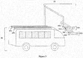
- the charging station can comprise a structure (6) with a charging mount (24).
- a charging connection (18) can be suspended from the charging mount.
- the charging connection can be a device similar to a components selected from the group consisting of a pantograph, a catenary arm, and a cantilever arm.
- the charging connection can have an adjustable shape or size such that an electrically conductive surface (14, 16) located on the charging connection can have an adjustable location.
- the charging connection is mechanically attached to the charging mount through a coupling, such as a positioning device (20, 26).
- the positioning device can be fixed or adjustable.
- the charging connection can comprise two electrically conductive surfaces (14, 16), such as conductive pads.
- the two electrically conductive surfaces can be electrically insulated from each other.
- the two electrically conductive surfaces can be supplied power through electrical wiring that electrically connects the electrically conductive surfaces to a power source (2).
- the electrical wiring can be housed within the charging connection (18), positioning device (20, 26), the charging mount (24), and the structure (6). Additional electrical wiring (4) can be used to establish an electrical connection to the power source (2).
- the power source can comprise any power source described herein.
- the vehicle (8) can comprise two contact plates or bars (10, 12) extending in a direction of vehicle movement (28).
- the two bars can be copper bars that are electrically connected to an energy storing device used to power the vehicle.
- FIG. 2 An alternate embodiment of the charging station is shown in Figure 2 .
- the electrically conductive surfaces (14, 16) can be connected to the charging mount through a cantilever arm (30).
- the cantilever arm can be adjusted in a vertical direction (22) to allow a vehicle (8) to pass under the conductive surfaces and then for establishing an electrical connection between the conductive surfaces and contact plates or bars (10, 12) on the vehicle.
- the electrical connections between the conductive surfaces and the power source (2) can be as described in Figure 1 .
- FIG. 3 shows another example of a charging station (36) and a vehicle (38).
- the vehicle may include one, two, three, four or more charge points, which may be contact bars, plates, or contacts of any other shape.
- it may be preferable to have at least two charge points.
- larger numbers of charge points may be desirable to charge multiple batteries (e.g., two charge points may be electrically connected to one battery or group of batteries, another two charge points may be electrically connected to another battery or group of batteries).
- Charging multiple battery sets in parallel may be desirable to speed up charge time and reduce system heating due to high current transfer. Any discussion of charge points or any other contacts may refer to contacts of any shape or format.
- Charge points (40a, 40b) may extend parallel to the direction of vehicle movement.
- the charge points may be mounted on top of the vehicle, such as on the roof of the vehicle.
- the charge points may be mounted on a side of a vehicle, in the roadway, or along another portion of the surface of the vehicle, or combinations thereof.
- the charge points may be formed of copper.
- the charge points may be formed of any conductive material, including but not limited to aluminum, silver, gold, or alloys or combinations thereof, and/or may be plated or clad with any conductive material including but not limited to copper, aluminum, silver, gold, alloys or combinations thereof, or any other conductive material.
- the charge points may be electrically insulated from one another.
- the charge points may be spaced apart from one another on top of the vehicle.
- the charging station (36) may include any number of contact assemblies (42a, 42b), such as collector braces.
- the contact assemblies may be electrically connected to charge points of a vehicle, which may function as electrodes. In some instances, the number of contact assemblies may match the number of charge points (40a, 40b) on the vehicle. For example, if two charge points are provided on the vehicle, two contact assemblies may be provided on the charging station. If four charge points are provided on the vehicle, four contact assemblies may be provided on the charging station.
- a pair of contact assemblies may be provided to make contact with a pair of charge points connected to a battery or battery pack.
- more contact assemblies may be provided (e.g., two contact assemblies may contact a pair of charge points which are in electrical communication with a battery or group of batteries, while two other contact assemblies may contact two other charge points which are in electrical contact with another battery or group of batteries). Charging multiple batteries at the same time may be desirable to speed up charge time and reduce system heating due to high current transfer.
- the multiple contact assemblies may be provided on the same arm of a charging station (e.g., four contact assemblies may be provided on the same overhang), while in other instances the multiple contact assemblies may be provided on a plurality of arms of a charging station (e.g., two contact assemblies may be provided on one overhang, while two contact assemblies are provided on a second overhang).
- the contact assemblies may include one or more guiding feature (44a, 44b, 44c, 44d) that may assist with guiding the charge points to contact conductive pads of the contact assemblies.
- a charging station can comprise a charging mount positioned above the ground and a charging connection suspended from the charging mount.
- the charging connection can be directly attached to the charging mount or attached to the charging mount through a coupling, such as a positioning device.
- the charging connection can be similar to a device selected from the group consisting of a pantograph, a catenary arm, and a cantilever arm.
- the charging connection may include, or also be referred to as, a charging chassis or frame, a charging skeleton or girder, or a charging overhang.
- the charging connection can be an inverted form of a device used to power a light rail car or an electric bus.
- the charging connection is a catenary arm suspended from the charging mount.
- the catenary arm can be supported by a cantilever arm.
- the charging can be for a two wire trolley bus such that the bus can operate as a trolley bus.
- a bus may be operating as a trolley bus by connecting to wires on a grid system.
- trolley poles may be lowered and the bus may operate as a battery electric bus, independent of the grid.
- a battery electric bus may operate independent of the grid and then encounter the grid.
- the poles may be raised into contact with the grid and the bus may be recharged while operating as a trolley bus.
- a bus may operate on the grid part of the time and off the grid part of the time.
- the bus may optionally use the on-grid time to charge the batteries on the bus, which may be used when the bus is off-grid.
- the charging connection may have a sensor or a mechanical or electro-mechanical height adjustment system to allow the charging connection to adjust to a height required to allow a vehicle to drive under the charging connection.
- the system for height adjustment can include the charging connection and/or the positioning device.
- the charging connection can be adjusted to a height required to establish an electrical connection.
- the electrical connection can be established for a time sufficient to charge the vehicle partially or fully.
- the charging connection can be designed in such a fashion that it is only activated when an electrical connection is made between the vehicle and the charging station and/or a signal is received from the vehicle to activate charging.
- the charging station can comprise mechanical and/or electrical protective devices to isolate conductive paths during non-contact situations. Such devices may be configured to allow energy flow only after receiving an electronic message (wireless, proximity switched contact, and/or manual trigger) or via direct mechanical activation.
- energy flow may automatically occur when the vehicle reaches the grid.
- a sensor may be provided that may allow the energy flow, while in other embodiments, mechanisms may be provided that may enable energy flow when the vehicle reaches the grid.
- Safety features may be provided, which may allow energy flow only in a desired manner.
- the vehicle e.g., bus
- the vehicle can adapt to existing light rail systems, where the vehicle is able to connect to the single overhead line and the ground coupling in the roadway rail.
- Power can be supplied to the charging connection using any means known to those skilled in the arts.
- an electrical power source used to power an electric vehicle such as a light rail or an electric bus can be used.
- the electrical power source can be a power source used to supply power to an overhead line for powering an electric train or a bus.
- the electrical power source can comprise a high voltage DC power source.
- the voltage can be between 400 and 800 volts DC, between 450 and 750 volts DC, or approximately 600 volts.
- the power source can be tapped and then transferred to a voltage converter to provide the correct voltage and current flow for the vehicle.
- the voltage converter can be a DC-DC charger.
- a rapid charger can be used to supply power to the charging connection.
- the rapid charger can be powered by conventional power sources or alternative power sources.
- the rapid charger is powered by hydrogen, conventional electricity obtained from a power grid, or any other type of power source.
- the rapid charger can be configured to provide a voltage and current to a vehicle.
- the power supply can comprise an energy buffer device.
- the energy buffer can be a capacitor or a battery.
- the capacitor can be a large ultra-capacitor.
- the battery can comprise a battery pack. Use of such a system may allow for off-peak charging of the energy buffer device at lower energy costs, then supply some or all of the daytime energy needs of the charging station.
- This energy buffer device may also allow the use of lower power infrastructure and/or charging supplies.
- the energy buffer device may allow for a slow charge of the energy buffer over time, then allow for rapid energy delivery through the charging connection.
- the energy buffer device can be utilized for utility grade emergency power or load balancing on a utility grid. Because the energy buffer device may be incorporated into large buildings for emergency power or into the utility grid for power balancing, the system can have cross-functionality and can be a joint project for customers of the services.
- the charging station can be located at a hub or any position along the route of a vehicle. In other embodiments of the invention, the charging station is located near an overhead line or an electric railway used to power a light rail vehicle, a train, or an electric bus.
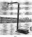
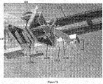
- FIG. 4 shows an example of a charging station in accordance with an embodiment of the invention.
- the charging station may comprise a structure (50) with a charging mount (51).
- the charging mount may comprise a charging connection (52).
- the charging connection may hang below the charging mount.
- the charging connection may extend downward and/or away from the charging mount.
- the charging connection (52) may be connected to a charging mount (51) via a coupling (55).
- the coupling may be fixed or adjustable.
- the coupling may be adjustable so that a charging connection may move vertically with respect to the charging mount.
- the coupling may be a vertical post with a flexible member such as a spring, an elastic component, a pneumatic device, a magnet, a weight or a gear.
- the flexible member may enable the charging connection to have a default height which may be adjustable when a force is exerted on it. For example, if a vehicle is passing under the charging connection and encounters a bump, the charging connection may accommodate the bump and maintain electrical contact with the vehicle. Similarly, when vehicles of slightly different height pass under the charging connection, they may be accommodated by a flexible coupling. This may be advantageous in situations where vehicle height may vary due to factors such as tire pressure or load weight.
- the coupling may allow for active adjustment of charging connection height, which may allow the charging station to accommodate vehicles of a wide range of heights.
- a sensor may be in communication with the coupling to inform the coupling of an incoming vehicle's height.
- the charging connection may include one or more contact assemblies (53a, 53b).
- a contact assembly may include a pair of guiding strips.
- a contact assembly may include one or more electrically conductive surfaces, such as a conductive pad, that may make electrical contact with a charge point.
- a contact assembly may include two conductive pads that may make electrical contact with a charge point.
- the charging structure and charging mount may have any structure or form that may enable the contact assemblies to contact the charge points of a vehicle.
- a charging mount may form a horizontal post or cantilever extending from the charging structure.
- the charging structure (50) may include a vertical post.
- the charging structure may have any other shape or configuration that may support the charging mount and/or charging connection at a desired height.
- the charging structure could even be part of a wall or pre-existing structure such as a bus stop waiting station.
- the length of the charging structure may be adjustable, which may result in the position of the charging connection being adjustable.
- the charging structure may be passively adjustable, such as if a vehicle passes beneath the charging connection, and causes the charging structure to accommodate the height of the vehicle.
- the charging structure may also be actively adjustable, such as if the vehicle approaching the charging station emits a signal indicating the vehicle type or height, so that the charging station may adjust its height to accommodate the incoming vehicle.
- the charging mount and structure may keep electrical connections from each of the contact assemblies segregated.
- electrical connections from two contact assemblies may be segregated within a single integrated structure (e.g., a single pole), or the structure may include two components (e.g., two poles) that may house electrical connections for each of the contact assemblies.
- the charging mount and structure may keep electrical connections from each of the conductive pads within a contact assembly segregated.
- the charging station may also include a stand (56).
- the stand may provide structural support to a charging structure (such as a post) and a charging mount/charging connection.
- the stand may be located at or form the base of a support structure of a charging station.
- the charging station may also include a power source (54). As discussed previously, the charging station may be powered by conventional power sources or alternative power sources.
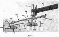
- FIG. 5 shows a view of the charging connection.
- the charging connection may form a charging chassis, charging frame, or charging overhang.
- the charging connection may include contact assemblies (60a, 60b).
- Each contact assembly may include one or more guiding feature (61a, 61b, 61c, 61d), such as a guiding strip or guiding slat, that may assist with forming an electrical contact between a charge point on a vehicle and the contact assembly.
- the contact assemblies may be spaced at a desired distance apart. For instance, two or more contact assemblies may be spaced at any desired distance apart. For example, the contact assemblies may be spaced about 5 cm, 10 cm, 15 cm, 20 cm, 25 cm, 30 cm, 35 cm, 40 cm, 45 cm, 50 cm, 60 cm, 70 cm, 80 cm or greater or lesser apart. Preferably, the contact assemblies may be spaced at a distance apart that is substantially the same as or closely approximates the distance between charge points on an approaching vehicle.
- the charging connection may also include a structure or feature that may keep the contact assemblies at a predetermined distance apart.
- a spacing bar (62) may be provided which may keep the contact assemblies (60a, 60b) at a predetermined distance apart.
- the predetermined distance may correspond to the distance between the charge points on the roof of the vehicle.
- the predetermined distance may be fixed, such that the contact assemblies remain at the same distance apart.
- the predetermined distance may be flexible.
- a spring or elastic feature may be provided within the spacing bar (62) such that the spacing bar is a predetermined distance apart at rest, but when force is exerted along the length of the spacing bar, the length of the spacing bar may compress or expand slightly.
- Such features may enable vehicles with charging points that may be at slightly different distances apart to approach a guiding feature, and then have the spacing bar adjust its length to accommodate the charging points sliding through the contact assemblies (60a, 60b).
- the spacing bar may include features that may enable the length of the spacing bar to be adjusted as desired.
- different vehicles may have charging points that are spaced apart at different distances.
- the vehicles may provide a signal to a charging station about the distance between the charging points, so that the charging station can adjust the length of the spacing bar to accommodate the charging point distances.
- a sensor or a hydraulic, mechanical or electro-mechanical length adjustment system for the spacing bar may be utilized. This may be useful in situations where different makes or models of vehicles may be conductive to charging points being spaced at different distances apart.
- Any discussion herein of the spacing bar may also apply to any other structure or component that may provide contact assemblies with a fixed or variable/controllable distance between one another.
- the charging connection may also include a positioning bar (64).
- the positioning bar may be a horizontal bar, which may be connected to a coupling (66), which is connected to a charging mount. Alternatively, the positioning bar may be directed connected to a charging mount.
- the positioning bar may be a rigid member of the charging connection.
- the charging connection may also include one or more arms (65a, 65b) extending from the positioning bar. The arms may be connected to the contact assemblies and/or the spacing bar. In some instances, the arms may extend downward from the positioning bar and/or horizontally away from the positioning bar. In some instances the arms may extend both downward and away from the positioning bar. Preferably, the arms may be rigid members.
- the arms may be connected to the positioning bar through a flexible connection or a rigid connection.
- the arms may be connected to the contact assemblies and/or spacing bar through a rigid connection or a flexible connection.
- the positioning bar, spacing bar, and one or more arms may form a chassis or frame for a charging connection.
- a charging connection with rigid members and one or more flexible connection may form a semi-rigid structure.
- the semi-rigid charging connection may advantageously provide enough structure and rigidity to orient the contact assemblies to accept charge points from a vehicle, while providing enough flexibility to accommodate variations in charge point placement or vehicle drive orientation.
- the charging connection may also include wires (63a, 63b, 63c, 63d) or other electrical connections that may be provided from conductive pads.
- wires 63a, 63b, 63c, 63d
- electrical connections between each of the contact assemblies may be segregated.
- electrical connections between each of the conductive pads may be segregated.
- the contact assemblies may be at substantially the same height. This may accommodate vehicles where the charge points of the vehicles are at substantially the same height. In some alternative embodiments, the contact assemblies may be arranged such that they are at different heights (e.g., 60a may hang lower than 60b), which may accommodate vehicles where the charge points are at different heights (e.g., one contact plate may extend from a vehicle room higher than another).
- FIG. 6A shows a view of a collector brace, which may also be referred to as a contact assembly, and vice versa.
- the collector brace may include a guiding feature, such as a guiding strip (70a, 70b).
- the guiding feature may be shaped such that it may capture a charging point, and guide it to one or more contact pads (71a, 71b).
- a pair of guiding features may form a 'V' shape to capture the charging point, or may have any other shape, such as a "U" shape, or any shape that may have a larger opening that may funnel or guide the charge point to a smaller opening.
- the guiding features may start off at some distance apart, and then they may converge toward one another at electrically conductive surfaces of the guiding features. This funneling aspect may enable the guiding features to have some tolerance in capturing the charge points from a vehicle.
- the charge points may be captured at the wide end of the funnel, and be directed toward the electrically conductive surface, which may be spaced closer
- a guiding feature may include an electrically conductive surface, which in some embodiments may be a contact pad.
- the contact pads (71a, 71b) may be metallic or non-metallic conductive pads and may or may not be replaceable. A preferable method would be to have replaceable pads that can be changed when the conductive portion is damaged or used.
- the contact pads may be conductive carbon pads. Part of the carbon pads may scrape off whenever a charge point slides between the contact pads. In such instances, the carbon pads may be replaceable.
- any other conductive materials such as metals, or metal alloys
- the contact pads may be formed of a slippery material that may enable the charge points to slide through easily.
- two or more contact pads may be provided per collector brace. In other embodiments, only one contact pad may be provided per collector brace. Different collector braces may or may not have the same number of contact pads.
- a charge point may slide between the electrically conductive surfaces of the collector brace, such that the charge point is sandwiched between the electrically conductive surfaces, such as the contact pads. Preferably when the charge point is between the electrically conductive surfaces, the charge point is contacting both contact pads.
- the contact pads may provide an electrically conductive surface area.
- the electrically conductive surface area may be 1 sq. cm, 2 sq. cm, 4 sq. cm, 6 sq. cm, 8 sq. cm, 10 sq. cm, 12 sq. cm, 15 sq. cm, 20 sq. cm, 25 sq. cm, 35 sq. cm, 50 sq. cm or greater.
- the contact pads may have any shape, such as rectangular, square, circular, oval, triangle, trapezoidal, hexagonal, etc.
- the contact pads may also have any dimensions.
- the contact pads may be 0.5 cm long, 1 cm long, 2 cm long, 4 cm long, 6 cm long, 8 cm long, 10 cm long, 12 cm long, 15 cm long, 20 cm long, 25 cm long, 30 cm long, 35 cm long, 40 cm long, 50 cm long, or longer.
- the contact pads may be 0.5 cm wide, 1 cm wide, 2 cm long, 4 cm wide, 6 cm wide, 8 cm wide, 10 cm wide, 12 cm wide, 15 cm wide, 20 cm wide, 25 cm wide, 30 cm wide, 35 cm wide, 40 cm wide, 50 cm wide, or wider. In some embodiments, the contact pads may be longer than they are wide.
- the contact pads may be of a sufficient width to provide leeway in the height of the charge points of a vehicle. For example, if the contact pads have a significant width, they may still contact the charge points of a vehicle, even if the vehicle is slightly shorter or taller than average. The charge points may end up contacting the contact pads toward the top of the contact pads or toward the bottom of the contact pads. Thus, having a substantial surface area to a contact pad may be advantageous in accommodating different vehicle heights, or irregularities in heights of the vehicle that may appear from different features of the terrain, such as bumps in the road.
- the charging station may include a horizontal roller, or similar feature, which may make preliminary contact with the roof mounted charge points (e.g., copper bars) to adjust the height.
- the horizontal roller, or any other guiding mechanism may be used to make contact with the roof of a vehicle, and provide a reference or guide that may enable the contact pads of the charging station to achieve a desired height. For example, if the vehicle-mounted charge points are about a couple of inches above the vehicle roof, a height guide, such as a roller may be provided several inches below the contact pads, so that when the roller contacts the roof of the vehicle, the height of the contact pads may be adjusted to be at the desired charging height.
- a horizontal roller may contact the roof of the vehicle, and roll over the roof of the vehicle, which may enable the vehicle to pass underneath without cause any damage to the vehicle.
- Other comparable mechanisms known in the art may be used, such as a guide that may have a soft slippery surface that may brush over the vehicle roof.
- the entire electrically conductive surface area of the contact pad may be contacting a charge point, such as a side of a contact plate on a vehicle.
- the surface area contact at the interface between the collector brace of the charging station and the charge point of vehicle may provide increased conductivity and electrical flow between the charging station and the vehicle, which may enable a battery of the device to be fast-charged.
- the vehicle may receive a signal when the contact plate on the vehicle makes contact with the contact pad or comes within a collector brace, in accordance with an embodiment of the invention. That signal may take command of the bus and cause it to stop. If the bus were to stop when making electrical contact, the contact plates on the bus would not have to be very long. This may advantageously provide less exposure to an electrically "hot" area.
- each collector brace has an electrically conductive surface on both sides of a charge point, such that the surface area connection between the charge point and the collector brace is increased.
- the guiding features may also include guiding pads (72a, 72b, 72c, 72d).
- the guiding pads may be formed of a slippery material that may enable charge points to slide through.
- a polymer or plastic may be used for the guiding pads.
- the guiding pads may be formed of a nylon.
- the guiding pads may include a coating or be clad with a slippery material.
- the guiding pads may be very long, or the contact pads may have a cover extending both fore and aft.
- the cover may be long enough to ensure that the charge bar on the roof is covered during charging. This may prevent a large bird or something similar from making contact between the two charge bars.
- the contact pads (71a, 71b) may be electrically connected to a power source. In some instances, the contact pads may be electrically connected through wires (73a, 73b).
- a charging station may include a pair of collector braces, or more.
- at least one collector brace may be for providing an electrical connection with an anode while at least one other collector brace may be for providing an electrical connection with a cathode, when the collector braces contact the charge points of a vehicle.
- the contact pads may function may be for contacting the same type of electrode.
- two collector braces may be provided, each comprising two contact pads. Both contact pads in one contact assembly may contact an anode, while both contact pads in the other contact assembly may contact a cathode.
- different contact pads within the same contact assembly may contact different electrodes.
- one collector brace may be provided, and one contact pad may contact a cathode while another may contact an anode.
- a collector brace may also include a casing (74).
- a casing may provide support or structure to the collector brace.
- a pressure assembly (75) may be provided that may exert force on one or more guiding feature (70a).
- the pressure assembly may exert force on one guiding feature, while the other guiding feature may be fixed.
- two pressure assemblies may be provided, whereby each pressure assembly exerts a force on a guiding feature. The force exerted on a guiding feature may be directed toward another guiding feature.
- one of the guiding features may have a lateral force directed to the other guiding feature (e.g., 70b), such that the guiding features would have a squeezing force.
- the contact pads of each guiding feature is pressed to the charge point when the charge point passes through, which ensures that an electrical connection is made.
- a large surface area electrical interface may be provided between the contact pads and the charge points. By exerting a sufficient amount of pressure on the connection, the large surface area contact can be ensured, which may ensure a low impedance across the junction.
- the pressure assembly may include any mechanism known in the art that may provide a sufficient lateral force between the contact pads to ensure a connection with the charge points (e.g., the contact pads may be pinching together to receive the charge point).
- features such as springs or elastics may be used in the pressure assembly.
- the pressure assembly may utilize a plurality of springs, that are connected to linkages and a bar that may allow a contact pad (71a) to remain substantially parallel to another contact pad (71b), without directly contacting the other contact pad.
- Figure 6B shows another view of a contact assembly (80), which may include guiding features (81 a, 81b), contact pads (82a, 82b), guiding pads (83a, 83b, 83c, 83d), a pressure assembly (84) which may exert a flexible pressure on one guiding feature (81a), and a fixed assembly (85) which may fix another guiding feature (81b) in place.
- the contact assembly (80) may also be connected to a spacing bar (86), and/or any other structure (87), such as an arm, that may connect the contact assembly (80) to a charging mount (88).
- FIG. 6C shows a close up of a pressure assembly in accordance with one embodiment of the invention.
- the pressure assembly may include multiple springs (90a, 90b) that may be connected to a bar (91) connected to a guiding feature (92a).
- Linkages (93a, 93b) may also be provided, which may be connected to the bar (91) and/or guiding feature (92a).
- the pressure assembly may keep the guiding feature (92) substantially parallel to another guiding feature (92b).
- the pressure assembly or other features or components may prevent the conductive pads from contacting one another.
- the charger connection there may be a cleaning brush or mechanism which will clean the vehicle rooftop bars as the vehicle enters and/or leaves the charging arm assembly. This may advantageously provide an improved electrical connection.
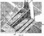
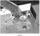
- FIG. 7A shows part of a charging chassis in accordance with an embodiment of the invention.
- a contact assembly (120) may be on a connecting structure, such as an arm (121a) and crossbar (121b), that connects the contact assembly to a charging mount (122).
- the contact assembly may also be connected to a spacing bar (125).
- the contact assembly may be connected to the spacing bar and/or arm.
- the contact assembly may include a fixed assembly (126), which may keep a guiding feature (124b) in place.
- a contact assembly may include at least one pressure assembly (127), and at least one fixed assembly.
- a contact assembly may include a plurality of pressure assemblies.
- a contact assembly may include a plurality of fixed assemblies, although preferably, a contact assembly includes at least one pressure assembly.
- the charging chassis may include a flexible connection (123).
- the flexible connection may be between an arm and a crossbar.
- the flexible connection (123) may provide flexibility to the connecting structure arm (121b) so that the contact assembly (120) on the arm (121b) may move relative to the charging mount (122) to accommodate the placement of one or more charge point on a vehicle.
- a vehicle may be driven to a charging station and placed so that one or more charge points is slightly offset from one or more contact assemblies.
- Guiding features (124a, 124b) of a contact assembly may capture a charge point of a vehicle, and the flexible connection (123) may enable to the contact assembly to shift to follow the path of the vehicle.
- the flexible connection (123) may allow the contact assembly (120) to shift substantially perpendicularly with respect to the direction of the vehicle travel.
- the contact assembly may be shifting laterally or horizontally.
- a flexible connection may enable flexibility within the connection structure that may enable one or more contact assemblies to move sideways relative to the vehicle to capture and contact one or more charge point of the vehicle.
- Figure 7B shows an example of a flexible connection of a connecting structure.
- the flexible connection may have any design that may provide flexibility to a connecting structure including springs, elastics, hinges, linkages, pivot points, pneumatic devices, weights, gears, hydraulics, or any other structure for flexible connection.
- springs (130a, 130b) may be provided that may enable a portion of a connecting structure to move laterally.
- a bar (131) of a connecting structure may slide sideways with respect to a fixed portion of the connecting structure (132).
- the portion of the connecting structure may move laterally, which may enable one or more contact assembly to move laterally to capture a charge point of vehicle.
- the flexible connection may enable contact assemblies to return to a center position, and may utilize springs, hydraulics, or gravity to recenter the connection assembly after use.
- a flexible connection may be structured such that a bar of a connecting structure may swing back and forth, which may allow a contact assembly to swing back and forth.
- the bar may swing back and forth if a pivot point or hinge is provided.
- Features such as springs, elastic, hydraulics, or gravity, may be used to enable the bar to swing back to its original position at rest.
- the flexible connection may be provided that may enable a bar (131) to swing rotatably around a connecting structure (132).
- the bar may pivot a little around the connecting structure, which may enable a contact assembly at the end of the bar to move vertically with respect to the connecting structure.
- there may be some give between the bar and the connecting structure that may result in limited vertical movement of the contact assembly.
- the vehicle can comprise two contact plates positioned on a top surface of the vehicle.
- the vehicle can comprise two bars attached to the roof of the vehicle.
- the two bars are conductive and function as contact plates for establishing a connection between the vehicle and a charging station.
- the two bars can be copper bars or any other type of conductive material.
- Other types of conductive material may include but are not limited to copper, aluminum, silver, gold, or alloys or combinations thereof, or may be plated/clad with a conductive material.
- the bars may be formed of the same materials, while in others, different materials may be utilized for different bars.
- the bars may be formed of materials that may be resistant to corrosion.
- the bars may be formed of materials that are slippery or high in lubricity.
- the bars are similar in fashion to a luggage rack on an SUV.
- the two bars or contact plates can extend in a direction that is parallel to a direction of vehicle movement. As shown in Figure 1, Figure 2 , and Figure 3 , the two bars (10, 12) can establish contact with a charging connection anywhere along the length of the bars. The orientation of the bars can reduce the need to align the vehicle in a forward or backward direction prior to charging the vehicle.
- Such devices may be configured to allow energy flow only after receiving an electronic message (wireless, proximity switched contact, and/or manual trigger) or via direct mechanical activation.
- the bars may also be installed at a prescribed gap height above the vehicle roofline to ensure any pooled water and/or other temporary or permanent conductive matter is kept at an appropriate dielectric gap height relative to the voltage differential.
- the vehicle may have a gauge or screen on the dash to inform a driver of the vehicle as to the state of charge of the vehicle.
- the vehicle can comprise a display for indicating that charging is in progress.
- the vehicle can comprise a charge monitoring device that can communicate charge status and vehicle rapid charge capabilities to other regional charging stations for characterization of energy availability.
- This monitoring system can be used for predictive modeling to estimate energy available at one or more charging stations on a route.
- the route can be fixed, controlled using GPS guidance, or spontaneous.
- the monitoring system can be used to determine how much energy the vehicle can collect during time available at a charging station.
- the vehicle can comprise a system for predicting range based on charge status, energy availability, and predicted energy availability obtained by transfer of charge from upcoming charging stations.
- a vehicle that is running behind schedule can skip or limit time spent at a charging station based on a prediction of energy required to reach at a subsequent energy station and/or the energy available at a subsequent energy station.
- a route can be modified based on energy available at one or more charging stations.
- the vehicle comprises a fast-charging energy storage device.
- the fast-charging energy storage device can be lithium titanate batteries or any other type of battery known to those skilled in the arts.
- the vehicle can be an electric bus or electric hybrid bus comprising the fast-charging energy storage device.
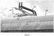
- FIG 8 shows an example of a vehicle (140) with at least one contact bar (141).
- the vehicle may pass under a charging station, which may include a charging mount (142).
- a contact bar may pass through a contact assembly (143).
- the contact assembly may include a guiding feature (144) that may guide the contact assembly to receive the contact bar.
- the charging station may also include a connecting structure (145) that may be flexible to enable lateral movement of the contact assembly, to allow the contact assembly to receive the contact bar (141).
- one or more contact bar of a vehicle may be a vertical plate with a rounded top. In some embodiments, this may advantageously allow for charging during icing conditions.
- a contact bar may be shaped such that it has two or more contact points with a vehicle. For example, as shown in Figure 8 , a contact bar (141) may have to contact points with a vehicle roof toward the front and end of the contact bar. In other embodiments, a contact bar may have one contact with a vehicle roof. For example, an entire length of a contact bar may be contacting a vehicle roof. Any number of contact points may be provided between a contact bar and a vehicle.
- a contact bar may have any dimensions that may enable it to be attached to a vehicle.
- a contact bar may be about 1 cm, 5 cm, 10 cm, 20 cm, 30 cm, 50 cm, 80 cm, 100 cm, 120 cm, or 140 cm long or longer.
- a contact bar may be about 0.5 cm tall, 1 cm tall, 2 cm tall, 3 cm tall, 4 cm tall, 5 cm tall, 7 cm tall, 10 cm tall, or 15 cm tall or taller.
- a contact bar may be sufficiently tall such that there may be some flexibility in allowing for a contact between the contact bar and a contact assembly of a charging station.
- a contact bar may be sufficiently tall so that the electrically conductive surfaces of a contact assembly may still contact the contact bar even if there are some variations in height, such as through bumps in the road, or different vehicle heights.
- a contact bar may also have any thickness.
- a contact bar may be about 0.2 cm thick, 0.5 cm thick, 0.7 cm thick, 1 cm thick, 1.5 cm thick, 2 cm thick, 3 cm thick, 4 cm thick, 6 cm thick, or thicker.
- a contact bar may be sufficiently thick such that when it passes between a contact assembly, both sides of the contact bar may contact guiding strips of the contact assembly, preferably along electrically conductive surfaces of the guiding strips.
- a contact may also be sufficiently thick such that when the contact bar passes between the guiding strips, a sufficient amount of pressure is exerted on the contact bar to ensure a strong electrical connection, and a lowered impedance.
- the amount of pressure may also be sufficient to ensure that the entire electrically conductive surface area is contacting the contact bar, and not just a portion of the surface.
- the thickness of the contact bar is a little greater than the space between the electrically conductive surfaces of a contact assembly when at rest. This may ensure that the guiding strips of a contact assembly may sufficiently grip, press, squeeze, clamp, or hold a contact bar to provide a sturdy electrical contact, while still allowing the contact bar to slide between the guiding strips.
- Two or more contact bars may also be spaced apart on the roof of the vehicle.
- the contact bars may be spaced at any desired distance apart.
- the contact bars may be spaced about 5 cm, 10 cm, 15 cm, 20 cm, 25 cm, 30 cm, 35 cm, 40 cm, 45 cm, 50 cm, 60 cm, 70 cm, 80 cm or greater or lesser apart.
- the contact bars are substantially parallel to one another.
- Transit buses can operate on a repetitive route system whereby the bus repeats its route at least every hour. As such, it passes the transit bus can pass a common point on an hourly basis and wait at that point for a cue to repeat the route. This can involve a wait of 10 to 20 minutes in many cases.
- the methods of the invention provide for a transit bus that can utilize the wait time to charge the transit bus.
- the transit bus can comprise a fast charging energy storage device that can completely recharged in 10 minutes. In some instances, the transit bus can be completely or substantially (e.g., more than 75%) charged within 5 minutes, 3 minutes, 2 minutes, or 1 minute.
- the fast charging energy storage device can be lithium titanate batteries or one of several other battery chemistries.
- an energy storing device is only partially charged. Partially charging the energy storing device can increase the life of the energy storing device by reducing the amount of charge transferred to the energy storage device during a single charging procedure.
- an electric transit bus designed in accordance with the invention described herein can average 11 to 13 miles per hour and consume approximately 1.5 to 3.0 kWh/mile. If the electric transit bus comprises an energy storing device with approximately 56 kWh of capacity, the electric transit bus can contain sufficient energy to propel the electric transit bus for approximately two to four hours without charging depending on driving application. That can allow for the electric transit bus to run indefinitely with an hourly charging of approximately 25% of the capacity of the energy storing device.
- This charging procedure can increase the life of the energy storing device relative to a charging procedure that charges the energy storing device from a completely drained state.
- a vehicle is charged by positioning the vehicle under a charging station.
- the charging station can comprise a charging connection that is engaged by adjusting the position of the charging connection.
- a control device in the vehicle can be used to transmit instructions to the charging station and/or the charging connection to establish an electrical connection between the charging connection and the vehicle.
- the charging connection may comprise a pair of contact assemblies with a known distance between them that correspond to the distance between the charge points on the roof of the vehicle. These charge contacts can use a system to return them to a center position that may utilize springs, hydraulics, or gravity to recenter the connection assembly after use.
- the contact assembly may comprise conductive pads with guides to ensure that the assembly moves laterally or vertically with respect to the direction of travel of the vehicle.
- the entire assembly may be energized if the support structure for the assembly can insulate voltages greater than the transmitted voltage.
- the contact pads may be metallic or non-metallic conductive pads and may or may not be replaceable. A preferable method would be to have replaceable pads that can be changed when the conductive portion is damaged or used.
- guidance into charge clamping devices can be accommodated by electronic guidance device aligned by laser or similar detection devices.
- the vehicle and/or energy storage controls system may be able to monitor vehicle route timetable performance. If there is excess time available for recharge, the controls systems can elect to reduce charger power and/or current to match the available break time in the route. As such there may be an increase in efficiency and system lifetime as a result of modulated charging performance.
- a charging station may also function as a discharger. For example, if a vehicle has a large amount of stored energy (e.g., in an on-board battery or energy storage unit), it may be desirable to discharge the vehicle somewhat, and transfer that energy to an energy storage unit of a charging station, or to provide it to a utility.
- a charging station may be able to operate both to charge and discharge a vehicle.
- the systems and methods may utilize or incorporate any methods, techniques, features or components known in the art or previously utilized. See, e.g., U.S. Patent No. Re 29,994 ; U.S. Patent No. 3,955,657 ; European Patent Application No. EP 2 014 505 A1 ; European Patent Application No. EP 1 997 668 A1 ; PCT Publication No. WO 2008/107767 A2 ; U.S. Patent Publication No. 2008/0277173 ; PCT Publication No. WO 2009/014543 , which are hereby incorporated by reference in their entirety.
Landscapes
- Engineering & Computer Science (AREA)
- Power Engineering (AREA)
- Mechanical Engineering (AREA)
- Transportation (AREA)
- Life Sciences & Earth Sciences (AREA)
- Sustainable Development (AREA)
- Sustainable Energy (AREA)
- Electric Propulsion And Braking For Vehicles (AREA)
- Charge And Discharge Circuits For Batteries Or The Like (AREA)
- Current-Collector Devices For Electrically Propelled Vehicles (AREA)
- Secondary Cells (AREA)
Applications Claiming Priority (4)
| Application Number | Priority Date | Filing Date | Title |
|---|---|---|---|
| US7745208P | 2008-07-01 | 2008-07-01 | |
| US17492609P | 2009-05-01 | 2009-05-01 | |
| PCT/US2009/049448 WO2010003021A2 (fr) | 2008-07-01 | 2009-07-01 | Stations de charge pour véhicules électriques |
| EP09774471.8A EP2296933B1 (fr) | 2008-07-01 | 2009-07-01 | Stations de charge pour véhicules électriques |
Related Parent Applications (1)
| Application Number | Title | Priority Date | Filing Date |
|---|---|---|---|
| EP09774471.8A Division EP2296933B1 (fr) | 2008-07-01 | 2009-07-01 | Stations de charge pour véhicules électriques |
Publications (3)
| Publication Number | Publication Date |
|---|---|
| EP3141417A2 true EP3141417A2 (fr) | 2017-03-15 |
| EP3141417A3 EP3141417A3 (fr) | 2017-04-12 |
| EP3141417B1 EP3141417B1 (fr) | 2019-02-27 |
Family
ID=41466598
Family Applications (2)
| Application Number | Title | Priority Date | Filing Date |
|---|---|---|---|
| EP16191966.7A Active EP3141417B1 (fr) | 2008-07-01 | 2009-07-01 | Chargeurs pour véhicules électriques |
| EP09774471.8A Active EP2296933B1 (fr) | 2008-07-01 | 2009-07-01 | Stations de charge pour véhicules électriques |
Family Applications After (1)
| Application Number | Title | Priority Date | Filing Date |
|---|---|---|---|
| EP09774471.8A Active EP2296933B1 (fr) | 2008-07-01 | 2009-07-01 | Stations de charge pour véhicules électriques |
Country Status (14)
| Country | Link |
|---|---|
| US (7) | US8324858B2 (fr) |
| EP (2) | EP3141417B1 (fr) |
| JP (1) | JP2011526858A (fr) |
| KR (1) | KR20110082120A (fr) |
| CN (1) | CN102123882A (fr) |
| AU (1) | AU2009266952B2 (fr) |
| BR (1) | BRPI0915229A2 (fr) |
| CA (1) | CA2729356C (fr) |
| CL (1) | CL2010001546A1 (fr) |
| CO (1) | CO6351766A2 (fr) |
| IL (1) | IL210178A (fr) |
| MX (1) | MX2010014551A (fr) |
| PE (1) | PE20110476A1 (fr) |
| WO (1) | WO2010003021A2 (fr) |
Cited By (4)
| Publication number | Priority date | Publication date | Assignee | Title |
|---|---|---|---|---|
| EP3131781B1 (fr) * | 2014-07-16 | 2018-11-07 | Siemens Mobility GmbH | Dispositif de charge pour un véhicule électrique rechargeable |
| WO2019175166A1 (fr) * | 2018-03-15 | 2019-09-19 | Schunk Bahn- Und Industrietechnik Gmbh | Unité de contact |
| EP3575138A1 (fr) * | 2018-05-14 | 2019-12-04 | Faiveley Transport Czech a.s. | Dispositif de transfert de courant électrique accru vers un trolleybus fixe, en particulier pour recharger des batteries de traction |
| RU2792044C2 (ru) * | 2018-03-15 | 2023-03-16 | Шунк Транзит Системз Гмбх | Контактный блок |
Families Citing this family (129)
| Publication number | Priority date | Publication date | Assignee | Title |
|---|---|---|---|---|
| CN102123882A (zh) | 2008-07-01 | 2011-07-13 | 普罗特拉公司 | 用于电动车辆的充电站 |
| US8006793B2 (en) | 2008-09-19 | 2011-08-30 | Better Place GmbH | Electric vehicle battery system |
| US20110223459A1 (en) * | 2008-09-19 | 2011-09-15 | Yoav Heichal | Multi-Motor Latch Assembly |
| FR2940201B1 (fr) * | 2008-12-22 | 2014-04-11 | Delachaux Sa | Systemes et ensemble de connexion pour la charge d'un vehicule electrique |
| FR2942750B1 (fr) * | 2009-03-09 | 2017-11-24 | Lohr Ind | Ensemble aerien pour la fourniture d'energie electrique a un vehicule terrestre. |
| US20100270859A1 (en) * | 2009-04-24 | 2010-10-28 | Zhengda Gong | Distributed Ultracapacitor Monitoring System Based on iCAN Protocol |
| US8839890B2 (en) * | 2009-05-26 | 2014-09-23 | Anthony Nicholas Caruso | Apparatus and system for low voltage direct current at industrial power recharging of hybrid high occupancy capacity on-road transportation vehicles |
| US20110145141A1 (en) * | 2009-10-02 | 2011-06-16 | James Blain | Method and apparatus for recharging electric vehicles |
| GB2475703A (en) * | 2009-11-26 | 2011-06-01 | Sylvan Ascent Inc | Electric vehicle charging station and charge receiving arrangement for a vehicle |
| JP2013515645A (ja) * | 2009-12-23 | 2013-05-09 | プロテラ インコーポレイテッド | 電気車両用の充電スタンド |
| US8493025B2 (en) | 2010-02-23 | 2013-07-23 | Optimization Technologies, Inc. | Electric vehicle charging station advertising systems |
| US8710798B2 (en) * | 2010-02-23 | 2014-04-29 | Optimization Technologies, Inc. | Electric vehicle charging station parking meter systems |
| US8604750B2 (en) | 2010-02-23 | 2013-12-10 | Optimization Technologies, Inc. | Electric vehicle charging stations with touch screen user interface |
| US20110238341A1 (en) * | 2010-03-25 | 2011-09-29 | Mehdi Etezadi-Amoli | High Power DC Kilowatt Hour Meter |
| FR2957861B1 (fr) * | 2010-03-29 | 2014-11-07 | Lohr Ind | Structure laterale superieure pour le captage occasionnel ou continu d'energie electrique motrice ou auxiliaire par un vehicule terrestre |
| JP5370585B2 (ja) * | 2010-04-19 | 2013-12-18 | 日産自動車株式会社 | 情報提供装置および情報提供方法 |
| MX2012012454A (es) * | 2010-04-26 | 2013-09-13 | Proterra Inc | Metodos y sistemas para la coleccion y carga automatica de un vehiculo electrico en una estacion de carga. |
| US8725330B2 (en) | 2010-06-02 | 2014-05-13 | Bryan Marc Failing | Increasing vehicle security |
| CA2812283A1 (fr) | 2010-09-21 | 2012-03-29 | Proterra Inc. | Systemes et procedes de chargement rapide equivalent presentant differentes configurations de stockage d'energie |
| US8890475B1 (en) * | 2010-09-28 | 2014-11-18 | Gilbert Scott Becker | Automobile charging and communications station |
| DE102010053528A1 (de) * | 2010-11-30 | 2012-05-31 | Dialogika Gesellschaft Für Angewandte Informatik Mbh | System für das automatische An- und Abdrahten während der Fahrt eines Oberleitungsfahrzeuges |
| WO2012109283A2 (fr) * | 2011-02-07 | 2012-08-16 | Media Cart, Inc. | Système de charge de contact pour des batteries montées sur un véhicule |
| US8511415B1 (en) * | 2011-02-22 | 2013-08-20 | Henry Copeland | Vehicle propulsion system |
| US10065628B2 (en) * | 2011-05-09 | 2018-09-04 | Ford Global Technologies, Llc | Location enhanced distance until charge (DUC) estimation for a plug-in hybrid electric vehicle (PHEV) |
| ES2627817T3 (es) * | 2011-06-09 | 2017-07-31 | Suntory Holdings Limited | Barrera de seguridad |
| US9545854B2 (en) * | 2011-06-13 | 2017-01-17 | General Electric Company | System and method for controlling and powering a vehicle |
| US9718371B2 (en) | 2011-06-30 | 2017-08-01 | International Business Machines Corporation | Recharging of battery electric vehicles on a smart electrical grid system |
| DE102011051627A1 (de) | 2011-07-07 | 2013-01-10 | Dr. Ing. H.C. F. Porsche Aktiengesellschaft | Baukastensystem für eine Batterie |
| DE102011051646A1 (de) * | 2011-07-07 | 2013-01-10 | Dr. Ing. H.C. F. Porsche Aktiengesellschaft | Kontaktiervorrichtung |
| JP2013027159A (ja) * | 2011-07-21 | 2013-02-04 | Sumitomo Electric Ind Ltd | 充電システム |
| FR2981016B1 (fr) * | 2011-10-06 | 2015-05-29 | Lohr Ind | Ensemble d'alimentation electrique a assistance a la prise de contact electrique sur une piste receptrice d'alimentation portee par un vehicule a propulsion electrique. |
| US20130105264A1 (en) * | 2011-10-26 | 2013-05-02 | Caterpillar Inc. | Pantograph assembly |
| JP5919525B2 (ja) * | 2011-11-22 | 2016-05-18 | パナソニックIpマネジメント株式会社 | 車両管理システム |
| JP6004774B2 (ja) * | 2011-12-16 | 2016-10-12 | モテックス プロダクツ カンパニー リミテッド | 電気自動車用バッテリーの脱着装置 |
| CN102611152A (zh) * | 2012-02-17 | 2012-07-25 | 苏州市莱赛电车技术有限公司 | 一种电动客车用充电装置 |
| US9637005B2 (en) * | 2012-03-30 | 2017-05-02 | Caterpillar Inc. | Display conveying trolley position to operator |
| US9436944B2 (en) | 2012-08-29 | 2016-09-06 | Optimization Technologies, Inc. | Electric vehicle charging station mobile device payment system |
| WO2014036319A1 (fr) * | 2012-08-30 | 2014-03-06 | Proterra Inc | Systèmes latéraux de charge de véhicule |
| CZ304117B6 (cs) * | 2012-09-14 | 2013-10-30 | Faiveley Transport Lekov A.S. | Zarízení pro dobíjení nezávislého elektrického trakcního vozidla |
| US9381818B2 (en) * | 2012-09-28 | 2016-07-05 | Siemens Aktiengesellschaft | Non-track-bound vehicle |
| EP3299212B1 (fr) * | 2012-11-13 | 2019-10-30 | Proterra Inc | Systèmes et procédés destinés à permettre une charge rapide d'un véhicule électrique à un poste de charge |
| US20140232331A1 (en) * | 2013-02-15 | 2014-08-21 | Qualcomm Incorporated | Vehicle wireless charging pad mounting systems |
| US20140239879A1 (en) * | 2013-02-22 | 2014-08-28 | Electro-Motive Diesel, Inc. | Battery charging system |
| US9266529B2 (en) | 2013-03-05 | 2016-02-23 | Toyota Motor Engineering & Manufacturing North America, Inc. | Known route HV control compensation |
| AU2014246942B2 (en) * | 2013-04-05 | 2018-03-01 | Hitachi Energy Ltd | Connecting apparatus for connecting an electrically powered vehicle to a charging station |
| JP6327412B2 (ja) | 2013-04-12 | 2018-05-23 | 三菱重工エンジニアリング株式会社 | 交通システム、及び給電方法 |
| US20140316939A1 (en) * | 2013-04-19 | 2014-10-23 | Honda Motor Co., Ltd. | System and method for selecting an electric vehicle charging station |
| US9931946B2 (en) | 2013-05-15 | 2018-04-03 | Volvo Truck Corporation | Method and arrangement for controlling charging of an energy storage system |
| DK3007925T3 (da) | 2013-06-14 | 2019-07-08 | Hedgehog Applications B V | Fremgangsmåde og system til anvendelse af jernbanekøretøjers regenerative bremseenergi |
| EP3010748B1 (fr) * | 2013-06-20 | 2017-08-02 | Volvo Truck Corporation | Agencement de protection de véhicule électrique |
| GB201311246D0 (en) * | 2013-06-25 | 2013-08-14 | Sylvan Ascent Inc | Vehicle charging connectors |
| PT3031104T (pt) * | 2013-08-09 | 2021-05-11 | Schunk Transit Sys Gmbh | Sistema de carregamento rápido e método para montagem de um dispositivo de contacto num dispositivo de montagem |
| DE102013216700B4 (de) * | 2013-08-22 | 2022-01-27 | Siemens Mobility GmbH | Ladung von batteriefahrtfähigen Straßenfahrzeugen |
| KR101517132B1 (ko) * | 2013-08-28 | 2015-05-13 | 한국철도기술연구원 | 철도차량의 전원공급장치 |
| PL224554B1 (pl) * | 2013-09-15 | 2017-01-31 | Ekoenergetyka Polska Spółka Z Ograniczoną Odpowiedzialnością | Konstrukcja złącza do ładowania akumulatorów pojazdu, zwłaszcza autobusu elektrycznego |
| CA2943731A1 (fr) * | 2014-03-26 | 2015-10-01 | Sequoia Automation S.R.L. | Systeme de charge d'energie associe a l'arret d'un vehicule electrique |
| CN106132761B (zh) * | 2014-03-27 | 2018-10-09 | 本田技研工业株式会社 | 电动车辆以及车辆供电方法 |
| GB2526118A (en) * | 2014-05-14 | 2015-11-18 | Sylvan Ascent Inc | Vehicle charging arrangement |
| US10017068B2 (en) | 2014-06-19 | 2018-07-10 | Proterra Inc. | Charging of a fleet of electric vehicles |
| EP3160809B1 (fr) * | 2014-06-27 | 2018-12-05 | Volvo Truck Corporation | Procédé de commande de l'état de charge d'un véhicule hybride rechargeable |
| FR3026355B1 (fr) | 2014-09-30 | 2017-12-29 | Bluetram | Procede et systeme d'assistance au positionnement d'un vehicule electrique par rapport a une station de recharge, station de recharge et vehicule electrique mettant en œuvre ce procede |
| CN104442454A (zh) * | 2014-12-02 | 2015-03-25 | 北京赛德高科铁道电气科技有限责任公司 | 一种储能式电动车辆的充电装置 |
| EP3031658B1 (fr) * | 2014-12-12 | 2020-03-18 | Siemens Mobility GmbH | Procédé de chargement d'un accumulateur d'énergie pour un véhicule |
| US9827865B2 (en) * | 2014-12-30 | 2017-11-28 | General Electric Company | Systems and methods for recharging vehicle-mounted energy storage devices |
| US10377251B2 (en) | 2015-03-26 | 2019-08-13 | Proterra Inc. | Electric vehicle charging interface |
| DE102015004119A1 (de) * | 2015-03-31 | 2016-10-06 | Audi Ag | Kraftfahrzeug mit einem elektrischen Energiespeicher und zwei Ladeschnittstellen, Ladesystem sowie Verfahren |
| US10300804B2 (en) | 2015-04-29 | 2019-05-28 | General Electric Company | Apparatus and method for automated positioning of a vehicle |
| EP3109087A1 (fr) * | 2015-06-24 | 2016-12-28 | Iveco France S.A. | Station d'alimentation electrique pour un bus urbain electrique |
| US9423465B1 (en) | 2015-06-30 | 2016-08-23 | Proterra Inc. | State of charge determination |
| US9321364B1 (en) | 2015-06-30 | 2016-04-26 | Proterra Inc. | Heated charging interface of electric vehicle |
| US10536026B2 (en) * | 2015-07-29 | 2020-01-14 | Toshiba International Corporation | Compact passenger station structure containing vehicle charging components |
| US9762228B2 (en) * | 2015-09-15 | 2017-09-12 | Qualcomm Incorporated | High-speed programmable clock divider |
| CN108045242A (zh) * | 2015-09-30 | 2018-05-18 | 艾能特(苏州)能源技术有限公司 | 用于新能源汽车的全天候充电系统 |
| US20170136887A1 (en) * | 2015-11-13 | 2017-05-18 | NextEv USA, Inc. | Electric vehicle aerial vehicle charging system and method of use |
| US10532663B2 (en) | 2015-11-13 | 2020-01-14 | Nio Usa, Inc. | Electric vehicle overhead charging system and method of use |
| US10632852B2 (en) | 2015-11-13 | 2020-04-28 | Nio Usa, Inc. | Electric vehicle optical charging system and method of use |
| US9987938B2 (en) | 2015-12-04 | 2018-06-05 | General Electric Company | Energy storage device, exchange apparatus, and method for exchanging an energy storage device |
| CN105391135B (zh) * | 2015-12-15 | 2019-03-15 | 郑州宇通客车股份有限公司 | 一种充电架和采用该充电架的充电装置 |
| US9878637B2 (en) * | 2015-12-28 | 2018-01-30 | Proterra Inc. | Method of docking an electric vehicle for charging |
| CN106926708A (zh) * | 2015-12-29 | 2017-07-07 | 王族伟 | 公交环境能平衡运行的触滑电车路过即被充电技术 |
| US9522603B1 (en) * | 2015-12-30 | 2016-12-20 | Proterra Inc. | Spring loaded brush carrier |
| FR3048387B1 (fr) * | 2016-03-02 | 2019-06-21 | Alstom Transport Technologies | Installation amelioree de recharge par conduction d'un vehicule |
| JP6758879B2 (ja) * | 2016-03-31 | 2020-09-23 | 株式会社東芝 | 切換制御装置および切換制御方法 |
| EP3225452B1 (fr) * | 2016-04-01 | 2021-06-09 | Carrosserie Hess AG | Station de charge pour un trolleybus |
| CN109562693B (zh) * | 2016-06-17 | 2022-09-09 | Abb瑞士股份有限公司 | 用于对电动车辆充电的装置和检验用于对电动车辆充电的装置与电动车辆之间的接触的方法 |
| CN106025408B (zh) * | 2016-06-22 | 2019-07-19 | 高鸿新能源科技有限公司 | 一种公交车充电控制方法及系统 |
| CN106374069B (zh) * | 2016-08-30 | 2020-05-08 | 欧阳路 | 一种电池组和充电装置 |
| US20190001830A1 (en) * | 2016-08-31 | 2019-01-03 | Faraday&Future Inc. | Method and system for auto-charging |
| DE102017200593A1 (de) * | 2017-01-16 | 2018-07-19 | Schunk Bahn- Und Industrietechnik Gmbh | Kontakteinheit für eine Ladestation und Verfahren zur Kontaktierung |
| CN107390685B (zh) * | 2017-07-14 | 2020-10-16 | 深圳市优必选科技有限公司 | 一种机器人的回充控制方法、机器人及机器人系统 |
| PL422790A1 (pl) * | 2017-09-08 | 2019-03-11 | Zakład Elektroniczny Sims Spółka Z Ograniczoną Odpowiedzialnością Spółka Komandytowa | System pozycjonowania pojazdu elektrycznego z pantografem |
| EP3724023A1 (fr) * | 2017-12-11 | 2020-10-21 | Zoox, Inc. | Charge par dessous de caisse de batteries de véhicule |
| US11034254B2 (en) * | 2017-12-11 | 2021-06-15 | Zoox, Inc. | Underbody charging of vehicle batteries |
| US10682921B2 (en) | 2017-12-11 | 2020-06-16 | Zoox, Inc. | Underbody charging of vehicle batteries |
| CN110116630B (zh) * | 2018-02-06 | 2021-04-20 | 比亚迪股份有限公司 | 轨道车辆的充电装置及轨道交通系统 |
| CN110116656B (zh) * | 2018-02-06 | 2022-11-11 | 比亚迪股份有限公司 | 轨道车辆的充电槽组件及轨道车辆的充电装置 |
| CN110203084B (zh) * | 2018-02-06 | 2021-04-20 | 比亚迪股份有限公司 | 轨道车辆的充电装置及轨道交通系统 |
| CN110116655B (zh) * | 2018-02-06 | 2022-11-11 | 比亚迪股份有限公司 | 轨道车辆的充电槽组件及轨道车辆的充电装置 |
| CN108286262A (zh) * | 2018-03-08 | 2018-07-17 | 中铁第四勘察设计院集团有限公司 | 一种智轨列车地面车站基础结构、车站及施工方法 |
| CZ309476B6 (cs) * | 2018-04-24 | 2023-02-15 | FAIVELEY TRANSPORT CZECH a.s | Zařízení pro napájení trolejbusu zvýšeným proudem |
| CN110654271B (zh) * | 2018-06-29 | 2022-03-18 | 比亚迪股份有限公司 | 轨道车辆的充电槽组件及具有其的充电装置 |
| CN110758135B (zh) * | 2018-07-27 | 2021-05-14 | 比亚迪股份有限公司 | 轨道车辆的充电装置、系统 |
| CN108725252A (zh) * | 2018-07-28 | 2018-11-02 | 共享智能铸造产业创新中心有限公司 | 充电支架 |
| US11148541B2 (en) | 2018-07-31 | 2021-10-19 | Proterra Inc. | Locating an electric vehicle at a charging station |
| CN110789406B (zh) * | 2018-08-01 | 2022-08-09 | 比亚迪股份有限公司 | 充电轨和具有其的轨道交通系统 |
| CN110789405B (zh) * | 2018-08-01 | 2022-08-09 | 比亚迪股份有限公司 | 充电轨和具有其的轨道交通系统 |
| US10566734B1 (en) * | 2018-08-02 | 2020-02-18 | Roboteq, Inc | System for facilitating electrical connection of a first electrical unit comprised in a first object with a second electrical unit comprised in a second object |
| US10906413B2 (en) | 2018-11-30 | 2021-02-02 | Proterra Inc. | Charging system including operatively independent chargers for an electric vehicle |
| TWI691141B (zh) * | 2018-12-26 | 2020-04-11 | 瑞軒科技股份有限公司 | 充電站、充電系統及充電方法 |
| CA3074829A1 (fr) | 2019-03-15 | 2020-09-15 | Proterra Inc. | Circuit de charge pour vehicules electriques |
| NL2022814B1 (en) * | 2019-03-26 | 2020-10-02 | Hapam B V | High voltage coupling contact |
| US11400822B2 (en) | 2019-05-24 | 2022-08-02 | Abb Schweiz Ag | Suspended charging cable system for electric vehicles |
| CN110303891A (zh) * | 2019-07-17 | 2019-10-08 | 西南交通大学 | 含减震结构的自润滑模块化金属滚筒电力机车受电弓弓头 |
| KR102113309B1 (ko) * | 2019-11-22 | 2020-05-20 | 중앙제어 주식회사 | 충전건 용 전선관 구조 |
| KR102333299B1 (ko) * | 2019-11-29 | 2021-12-01 | 대영코어텍(주) | 무가선 노면전차 전력공급장치 |
| KR102421278B1 (ko) * | 2019-12-06 | 2022-07-18 | 한국철도기술연구원 | 배터리 구동형 교통수단의 지붕 충전 감시 장치 |
| US11571979B2 (en) * | 2020-01-23 | 2023-02-07 | EVgo Services, LLC | Electric vehicle charging systems and platforms |
| US11225158B2 (en) | 2020-03-02 | 2022-01-18 | Proterra Inc. | Mediator system and method for controlling a charging control network |
| CN111572381B (zh) * | 2020-05-11 | 2024-02-13 | 浙江潮城科技发展有限公司 | 一种便于安装的充电桩用固定支架 |
| US11745613B2 (en) * | 2020-08-26 | 2023-09-05 | Cisco Technology, Inc. | System and method for electric vehicle charging and security |
| KR102299807B1 (ko) * | 2021-01-11 | 2021-09-08 | 주식회사 기람엔지니어링 | 전기철도 전원공급 시스템 |
| US20220227258A1 (en) * | 2021-01-20 | 2022-07-21 | Abb Schweiz Ag | Power line system with ripple generator for electric vehicles |
| KR102556306B1 (ko) * | 2021-02-08 | 2023-07-17 | 한국자동차연구원 | 전기버스 충전 장치 |
| CN114394098B (zh) | 2021-04-16 | 2023-06-23 | 阿波罗智联(北京)科技有限公司 | 车辆停靠的方法、装置、电子设备和可读存储介质 |
| US11745608B2 (en) | 2021-05-07 | 2023-09-05 | Electric Power Research Institute, Inc. | Connector system for conductive charging of electric vehicle |
| US11590856B2 (en) * | 2021-05-14 | 2023-02-28 | Wesley Zhou | Robotic car charger attachment apparatus |
| CN114394015A (zh) * | 2022-01-23 | 2022-04-26 | 赖翔 | 一种新能源汽车用自动对齐式充电桩 |
| WO2024037723A1 (fr) * | 2022-08-19 | 2024-02-22 | Schunk Transit Systems Gmbh | Unité de positionnement, en particulier pour une station de charge, et procédé de mise en contact |
| US11775872B1 (en) | 2022-12-01 | 2023-10-03 | Recentive Analytics, Inc. | Techniques for identifying optimal EV charging station locations |
Family Cites Families (61)
| Publication number | Priority date | Publication date | Assignee | Title |
|---|---|---|---|---|
| US522617A (en) | 1894-07-10 | Apparatus for manufacturing caustic alkali | ||
| US829853A (en) | 1906-02-16 | 1906-08-28 | Thomas Davis | Rotary engine. |
| US3955657A (en) * | 1974-02-15 | 1976-05-11 | Oscar Bossi | Electric traction transportation system with storage battery powered vehicles and fast recharge at the vehicle stops |
| USRE29994E (en) | 1973-02-15 | 1979-05-15 | Electric traction transportation system with storage battery powered vehicles and fast recharge at the vehicle stops | |
| FR2277694A1 (fr) * | 1974-07-09 | 1976-02-06 | Tregie | Dispositif d'alimentation en courant electrique de vehicules terrestres |
| US4158802A (en) * | 1977-12-27 | 1979-06-19 | Rose Ii William R | Rechargeable battery powered electric car and recharging station therefor |
| EP0026147B1 (fr) * | 1979-09-25 | 1983-11-16 | Faiveley S.A. | Dispositif d'emperchage automatique d'un véhicule électrique du genre trolleybus |
| DE3613626A1 (de) * | 1986-04-23 | 1987-10-29 | Roth Werke Gmbh | Verkehrsanlage |
| GB2253379B (en) | 1991-02-13 | 1995-04-26 | Nelson James Kruschandl | Comprehensive electric motor road vehicle system |
| GB2256178B (en) * | 1991-05-31 | 1995-01-18 | David Saunders | Improvements relating to battery powered vehicle systems |
| US5202617A (en) * | 1991-10-15 | 1993-04-13 | Norvik Technologies Inc. | Charging station for electric vehicles |
| EP0552737A1 (fr) | 1992-01-22 | 1993-07-28 | Hughes Aircraft Company | Chargeur résistant aux intempéries monté lelong |
| FR2692528B1 (fr) | 1992-06-17 | 1995-01-20 | Delachaux Sa | Dispositif de captation d'électricité pour un véhicule tel qu'un trolleybus ou un tramway. |
| JPH0686407A (ja) | 1992-08-31 | 1994-03-25 | Isuzu Motors Ltd | ハイブリッド電源電気自動車 |
| DE4236286A1 (de) * | 1992-10-28 | 1994-05-05 | Daimler Benz Ag | Verfahren und Anordnung zum automatischen berührungslosen Laden |
| US5315227A (en) | 1993-01-29 | 1994-05-24 | Pierson Mark V | Solar recharge station for electric vehicles |
| US5252078A (en) * | 1993-02-23 | 1993-10-12 | Albert Langenbahn | Drive-up electric receptacle |
| US5464082A (en) * | 1993-08-03 | 1995-11-07 | Young; Peter Y. S. | Electrical vehicle transportation system |
| US5592883A (en) * | 1994-05-16 | 1997-01-14 | Andress, Iii; F. Jay | Monorail transportation system and vehicle for traveling thereon |
| US5498948A (en) * | 1994-10-14 | 1996-03-12 | Delco Electornics | Self-aligning inductive charger |
| US5847537A (en) * | 1996-10-19 | 1998-12-08 | Parmley, Sr.; Daniel W. | Electric vehicle charging station system |
| US5939857A (en) * | 1997-12-15 | 1999-08-17 | Barrier Free Lifts, Inc. | In-track charging station and method |
| DE20013399U1 (de) * | 2000-08-03 | 2000-11-02 | Chai Wellmon | Ladestation für elektrisch betriebene Fahrzeuge |
| FR2819759B1 (fr) * | 2001-01-24 | 2003-05-23 | Alstom | Systeme d'alimentation d'un vehicule a traction electrique |
| US7549521B2 (en) * | 2001-02-15 | 2009-06-23 | Integral Technologies, Inc. | Low cost electrical power connectivity for railway systems manufactured from conductive loaded resin-based materials |
| US6673479B2 (en) | 2001-03-15 | 2004-01-06 | Hydrogenics Corporation | System and method for enabling the real time buying and selling of electricity generated by fuel cell powered vehicles |
| FR2822764B1 (fr) | 2001-03-29 | 2003-05-16 | Alstom | Procede et dispositif de pilotage de l'alimentation en energie d'un vehicule a traction electrique destine a fonctionner en mode d'alimentation externe ou en mode d'alimentation autonome |
| JP3896258B2 (ja) | 2001-04-25 | 2007-03-22 | 株式会社日立製作所 | 自動車電源装置 |
| JP3659204B2 (ja) | 2001-08-30 | 2005-06-15 | 日産自動車株式会社 | 移動体用燃料電池パワープラント |
| JP3939546B2 (ja) | 2001-12-06 | 2007-07-04 | パナソニック・イーブイ・エナジー株式会社 | 電動車両の電池電源装置 |
| DE10218258A1 (de) | 2002-04-24 | 2003-11-13 | Dwa Deutsche Waggonbau Gmbh | Energieversorgungseinrichtung für Reisezugwagen und/oder Triebwagen |
| KR100626855B1 (ko) | 2003-08-28 | 2006-09-21 | 정경균 | 풍력 및 태양열을 이용한 전기자동차 축전지 충전터널구조 및 충전도로상의 전기자동차 축전장치 |
| JP4599960B2 (ja) | 2004-09-17 | 2010-12-15 | ソニー株式会社 | 固体撮像素子 |
| CN1261319C (zh) * | 2004-11-11 | 2006-06-28 | 北京电巴科技有限公司 | 一种电动公交系统 |
| CN1647967A (zh) * | 2005-03-12 | 2005-08-03 | 李荟敏 | 电动汽车的集电装置 |
| CN2853496Y (zh) | 2005-03-21 | 2007-01-03 | 钱致疆 | 一种逐站自动充电式多电源无轨电车 |
| US8469122B2 (en) * | 2005-05-24 | 2013-06-25 | Rearden, Llc | System and method for powering vehicle using radio frequency signals and feedback |
| US20060273756A1 (en) * | 2005-06-06 | 2006-12-07 | Bowling David A | Opportunity charging system for battery powered mining equipment |
| US20070062771A1 (en) * | 2005-09-17 | 2007-03-22 | Dingzhong Li | An electrical vehicle transportation system |
| CN1751910A (zh) * | 2005-10-17 | 2006-03-29 | 上海交大神舟汽车设计开发有限公司 | 超级电容快速充电公交电车 |
| FR2892069B1 (fr) | 2005-10-17 | 2014-07-18 | Pvi | Poste de recharge et vehicule electrique associe |
| KR20070073408A (ko) * | 2006-01-05 | 2007-07-10 | 엘에스전선 주식회사 | 차량용 비상 전력 공급장치 |
| US20080023233A1 (en) * | 2006-07-27 | 2008-01-31 | Sunmover Aps | Drive Unit For Trailers And Caravans |
| US20080052145A1 (en) | 2006-08-10 | 2008-02-28 | V2 Green, Inc. | Power Aggregation System for Distributed Electric Resources |
| JP4691000B2 (ja) * | 2006-11-15 | 2011-06-01 | 三菱重工業株式会社 | 移動体の非接触給電装置 |
| CN101003260B (zh) * | 2007-01-16 | 2011-06-15 | 上海交大神舟汽车设计开发有限公司 | 一种公交电车候车站充电装置 |
| US7679336B2 (en) | 2007-02-27 | 2010-03-16 | Ford Global Technologies, Llc | Interactive battery charger for electric vehicle |
| JP4568736B2 (ja) | 2007-02-27 | 2010-10-27 | 三菱重工業株式会社 | 架線レス交通システム及びその充電方法 |
| US20080221746A1 (en) | 2007-03-05 | 2008-09-11 | Plishner Paul J | System for providing or receiving electric power from a parked vehicle |
| FR2916696B1 (fr) | 2007-05-31 | 2010-08-27 | Iveco France | Systeme de transport en commun, vehicule electrique et station de regeneration pour ce systeme |
| WO2009001788A1 (fr) | 2007-06-25 | 2008-12-31 | Nagae Takeshima | Véhicule et système de trafic |
| US8307967B2 (en) * | 2007-07-04 | 2012-11-13 | Satyajit Patwardhan | Widely deployable charging system for vehicles |
| CN101828318A (zh) | 2007-07-26 | 2010-09-08 | 绿箱子技术股份有限公司 | 用于在电网和车辆之间传送电功率的系统和方法 |
| US7693609B2 (en) | 2007-09-05 | 2010-04-06 | Consolidated Edison Company Of New York, Inc. | Hybrid vehicle recharging system and method of operation |
| US8378632B2 (en) * | 2007-10-02 | 2013-02-19 | The Gillette Company | Circuit arrangement with multiple batteries |
| US20090115368A1 (en) * | 2007-11-07 | 2009-05-07 | James Kenneth Bullis | Distributed electric power generation |
| US8138718B2 (en) * | 2007-11-27 | 2012-03-20 | Gordon Ewbank Dower | Docking bay for conditionally supplying battery recharging energy to a vehicle utilizing non plug-in electrical contact between a pair of docking bay contacts and a pair of vehicle contacts |
| CN102123882A (zh) | 2008-07-01 | 2011-07-13 | 普罗特拉公司 | 用于电动车辆的充电站 |
| US8294286B2 (en) * | 2008-07-15 | 2012-10-23 | F3 & I2, Llc | Network of energy generating modules for transfer of energy outputs |
| US8058841B2 (en) * | 2008-10-25 | 2011-11-15 | Ford Global Technologies, Llc | Retractable overhead charging cord dispenser for vehicles |
| JP2013515645A (ja) | 2009-12-23 | 2013-05-09 | プロテラ インコーポレイテッド | 電気車両用の充電スタンド |
-
2009
- 2009-07-01 CN CN2009801295799A patent/CN102123882A/zh active Pending
- 2009-07-01 EP EP16191966.7A patent/EP3141417B1/fr active Active
- 2009-07-01 MX MX2010014551A patent/MX2010014551A/es active IP Right Grant
- 2009-07-01 WO PCT/US2009/049448 patent/WO2010003021A2/fr active Application Filing
- 2009-07-01 CA CA2729356A patent/CA2729356C/fr active Active
- 2009-07-01 US US12/496,569 patent/US8324858B2/en active Active
- 2009-07-01 AU AU2009266952A patent/AU2009266952B2/en active Active
- 2009-07-01 KR KR1020117002746A patent/KR20110082120A/ko not_active Application Discontinuation
- 2009-07-01 JP JP2011516856A patent/JP2011526858A/ja active Pending
- 2009-07-01 BR BRPI0915229A patent/BRPI0915229A2/pt not_active IP Right Cessation
- 2009-07-01 EP EP09774471.8A patent/EP2296933B1/fr active Active
- 2009-07-01 PE PE2010001223A patent/PE20110476A1/es not_active Application Discontinuation
-
2010
- 2010-12-22 IL IL210178A patent/IL210178A/en active IP Right Grant
- 2010-12-23 CL CL2010001546A patent/CL2010001546A1/es unknown
- 2010-12-30 CO CO10164918A patent/CO6351766A2/es active IP Right Grant
-
2012
- 2012-11-15 US US13/678,493 patent/US8829853B2/en active Active
-
2014
- 2014-08-01 US US14/449,842 patent/US9446672B2/en active Active
-
2016
- 2016-08-23 US US15/244,277 patent/US10112498B2/en active Active
-
2017
- 2017-04-12 US US15/485,385 patent/US9908435B2/en active Active
-
2018
- 2018-10-02 US US16/149,919 patent/US11345245B2/en active Active
-
2022
- 2022-05-02 US US17/661,680 patent/US20220258625A1/en not_active Abandoned
Cited By (5)
| Publication number | Priority date | Publication date | Assignee | Title |
|---|---|---|---|---|
| EP3131781B1 (fr) * | 2014-07-16 | 2018-11-07 | Siemens Mobility GmbH | Dispositif de charge pour un véhicule électrique rechargeable |
| WO2019175166A1 (fr) * | 2018-03-15 | 2019-09-19 | Schunk Bahn- Und Industrietechnik Gmbh | Unité de contact |
| US11364807B2 (en) | 2018-03-15 | 2022-06-21 | Schunk Transit Systems Gmbh | Contact unit |
| RU2792044C2 (ru) * | 2018-03-15 | 2023-03-16 | Шунк Транзит Системз Гмбх | Контактный блок |
| EP3575138A1 (fr) * | 2018-05-14 | 2019-12-04 | Faiveley Transport Czech a.s. | Dispositif de transfert de courant électrique accru vers un trolleybus fixe, en particulier pour recharger des batteries de traction |
Also Published As
Similar Documents
| Publication | Publication Date | Title |
|---|---|---|
| US20220258625A1 (en) | Charging systems for electric vehicles | |
| US11453299B2 (en) | Electric vehicles and charging stations | |
| AU2013225075A1 (en) | Current transmission device for charging electrical energy stores of vehicles at overhead charging stations | |
| AU2013216685A1 (en) | Charging stations for electric vehicles | |
| JP7295339B2 (ja) | エネルギー伝送装置を備える電気自動車 |
Legal Events
| Date | Code | Title | Description |
|---|---|---|---|
| PUAI | Public reference made under article 153(3) epc to a published international application that has entered the european phase |
Free format text: ORIGINAL CODE: 0009012 |
|
| STAA | Information on the status of an ep patent application or granted ep patent |
Free format text: STATUS: THE APPLICATION HAS BEEN PUBLISHED |
|
| PUAL | Search report despatched |
Free format text: ORIGINAL CODE: 0009013 |
|
| AC | Divisional application: reference to earlier application |
Ref document number: 2296933 Country of ref document: EP Kind code of ref document: P |
|
| AK | Designated contracting states |
Kind code of ref document: A2 Designated state(s): AT BE BG CH CY CZ DE DK EE ES FI FR GB GR HR HU IE IS IT LI LT LU LV MC MK MT NL NO PL PT RO SE SI SK SM TR |
|
| AK | Designated contracting states |
Kind code of ref document: A3 Designated state(s): AT BE BG CH CY CZ DE DK EE ES FI FR GB GR HR HU IE IS IT LI LT LU LV MC MK MT NL NO PL PT RO SE SI SK SM TR |
|
| RIC1 | Information provided on ipc code assigned before grant |
Ipc: B60L 5/42 20060101ALI20170303BHEP Ipc: B60L 11/18 20060101AFI20170303BHEP |
|
| STAA | Information on the status of an ep patent application or granted ep patent |
Free format text: STATUS: REQUEST FOR EXAMINATION WAS MADE |
|
| 17P | Request for examination filed |
Effective date: 20171012 |
|
| RBV | Designated contracting states (corrected) |
Designated state(s): AT BE BG CH CY CZ DE DK EE ES FI FR GB GR HR HU IE IS IT LI LT LU LV MC MK MT NL NO PL PT RO SE SI SK SM TR |
|
| STAA | Information on the status of an ep patent application or granted ep patent |
Free format text: STATUS: EXAMINATION IS IN PROGRESS |
|
| 17Q | First examination report despatched |
Effective date: 20180214 |
|
| RIC1 | Information provided on ipc code assigned before grant |
Ipc: B60L 11/18 20060101AFI20180718BHEP Ipc: B60L 5/00 20060101ALI20180718BHEP Ipc: B60M 7/00 20060101ALI20180718BHEP Ipc: B60L 5/42 20060101ALI20180718BHEP Ipc: H02J 7/00 20060101ALI20180718BHEP |
|
| GRAP | Despatch of communication of intention to grant a patent |
Free format text: ORIGINAL CODE: EPIDOSNIGR1 |
|
| STAA | Information on the status of an ep patent application or granted ep patent |
Free format text: STATUS: GRANT OF PATENT IS INTENDED |
|
| INTG | Intention to grant announced |
Effective date: 20180917 |
|
| RIN1 | Information on inventor provided before grant (corrected) |
Inventor name: HORTH, JOHN Inventor name: GOLDMAN, JOSHUA Inventor name: HILL, DALE Inventor name: WALKER, MICHAEL |
|
| GRAS | Grant fee paid |
Free format text: ORIGINAL CODE: EPIDOSNIGR3 |
|
| GRAA | (expected) grant |
Free format text: ORIGINAL CODE: 0009210 |
|
| STAA | Information on the status of an ep patent application or granted ep patent |
Free format text: STATUS: THE PATENT HAS BEEN GRANTED |
|
| AC | Divisional application: reference to earlier application |
Ref document number: 2296933 Country of ref document: EP Kind code of ref document: P |
|
| AK | Designated contracting states |
Kind code of ref document: B1 Designated state(s): AT BE BG CH CY CZ DE DK EE ES FI FR GB GR HR HU IE IS IT LI LT LU LV MC MK MT NL NO PL PT RO SE SI SK SM TR |
|
| REG | Reference to a national code |
Ref country code: GB Ref legal event code: FG4D |
|
| REG | Reference to a national code |
Ref country code: CH Ref legal event code: EP |
|
| REG | Reference to a national code |
Ref country code: AT Ref legal event code: REF Ref document number: 1100823 Country of ref document: AT Kind code of ref document: T Effective date: 20190315 |
|
| REG | Reference to a national code |
Ref country code: IE Ref legal event code: FG4D |
|
| REG | Reference to a national code |
Ref country code: DE Ref legal event code: R096 Ref document number: 602009057281 Country of ref document: DE |
|
| REG | Reference to a national code |
Ref country code: NL Ref legal event code: FP |
|
| REG | Reference to a national code |
Ref country code: SE Ref legal event code: TRGR |
|
| REG | Reference to a national code |
Ref country code: NO Ref legal event code: T2 Effective date: 20190227 |
|
| REG | Reference to a national code |
Ref country code: LT Ref legal event code: MG4D |
|
| PG25 | Lapsed in a contracting state [announced via postgrant information from national office to epo] |
Ref country code: LT Free format text: LAPSE BECAUSE OF FAILURE TO SUBMIT A TRANSLATION OF THE DESCRIPTION OR TO PAY THE FEE WITHIN THE PRESCRIBED TIME-LIMIT Effective date: 20190227 Ref country code: PT Free format text: LAPSE BECAUSE OF FAILURE TO SUBMIT A TRANSLATION OF THE DESCRIPTION OR TO PAY THE FEE WITHIN THE PRESCRIBED TIME-LIMIT Effective date: 20190627 Ref country code: FI Free format text: LAPSE BECAUSE OF FAILURE TO SUBMIT A TRANSLATION OF THE DESCRIPTION OR TO PAY THE FEE WITHIN THE PRESCRIBED TIME-LIMIT Effective date: 20190227 |
|
| PG25 | Lapsed in a contracting state [announced via postgrant information from national office to epo] |
Ref country code: IS Free format text: LAPSE BECAUSE OF FAILURE TO SUBMIT A TRANSLATION OF THE DESCRIPTION OR TO PAY THE FEE WITHIN THE PRESCRIBED TIME-LIMIT Effective date: 20190627 Ref country code: BG Free format text: LAPSE BECAUSE OF FAILURE TO SUBMIT A TRANSLATION OF THE DESCRIPTION OR TO PAY THE FEE WITHIN THE PRESCRIBED TIME-LIMIT Effective date: 20190527 Ref country code: HR Free format text: LAPSE BECAUSE OF FAILURE TO SUBMIT A TRANSLATION OF THE DESCRIPTION OR TO PAY THE FEE WITHIN THE PRESCRIBED TIME-LIMIT Effective date: 20190227 Ref country code: LV Free format text: LAPSE BECAUSE OF FAILURE TO SUBMIT A TRANSLATION OF THE DESCRIPTION OR TO PAY THE FEE WITHIN THE PRESCRIBED TIME-LIMIT Effective date: 20190227 Ref country code: GR Free format text: LAPSE BECAUSE OF FAILURE TO SUBMIT A TRANSLATION OF THE DESCRIPTION OR TO PAY THE FEE WITHIN THE PRESCRIBED TIME-LIMIT Effective date: 20190528 |
|
| REG | Reference to a national code |
Ref country code: AT Ref legal event code: MK05 Ref document number: 1100823 Country of ref document: AT Kind code of ref document: T Effective date: 20190227 |
|
| PG25 | Lapsed in a contracting state [announced via postgrant information from national office to epo] |
Ref country code: ES Free format text: LAPSE BECAUSE OF FAILURE TO SUBMIT A TRANSLATION OF THE DESCRIPTION OR TO PAY THE FEE WITHIN THE PRESCRIBED TIME-LIMIT Effective date: 20190227 Ref country code: SK Free format text: LAPSE BECAUSE OF FAILURE TO SUBMIT A TRANSLATION OF THE DESCRIPTION OR TO PAY THE FEE WITHIN THE PRESCRIBED TIME-LIMIT Effective date: 20190227 Ref country code: EE Free format text: LAPSE BECAUSE OF FAILURE TO SUBMIT A TRANSLATION OF THE DESCRIPTION OR TO PAY THE FEE WITHIN THE PRESCRIBED TIME-LIMIT Effective date: 20190227 Ref country code: DK Free format text: LAPSE BECAUSE OF FAILURE TO SUBMIT A TRANSLATION OF THE DESCRIPTION OR TO PAY THE FEE WITHIN THE PRESCRIBED TIME-LIMIT Effective date: 20190227 Ref country code: RO Free format text: LAPSE BECAUSE OF FAILURE TO SUBMIT A TRANSLATION OF THE DESCRIPTION OR TO PAY THE FEE WITHIN THE PRESCRIBED TIME-LIMIT Effective date: 20190227 Ref country code: CZ Free format text: LAPSE BECAUSE OF FAILURE TO SUBMIT A TRANSLATION OF THE DESCRIPTION OR TO PAY THE FEE WITHIN THE PRESCRIBED TIME-LIMIT Effective date: 20190227 Ref country code: IT Free format text: LAPSE BECAUSE OF FAILURE TO SUBMIT A TRANSLATION OF THE DESCRIPTION OR TO PAY THE FEE WITHIN THE PRESCRIBED TIME-LIMIT Effective date: 20190227 |
|
| REG | Reference to a national code |
Ref country code: DE Ref legal event code: R097 Ref document number: 602009057281 Country of ref document: DE |
|
| PG25 | Lapsed in a contracting state [announced via postgrant information from national office to epo] |
Ref country code: SM Free format text: LAPSE BECAUSE OF FAILURE TO SUBMIT A TRANSLATION OF THE DESCRIPTION OR TO PAY THE FEE WITHIN THE PRESCRIBED TIME-LIMIT Effective date: 20190227 Ref country code: PL Free format text: LAPSE BECAUSE OF FAILURE TO SUBMIT A TRANSLATION OF THE DESCRIPTION OR TO PAY THE FEE WITHIN THE PRESCRIBED TIME-LIMIT Effective date: 20190227 |
|
| PG25 | Lapsed in a contracting state [announced via postgrant information from national office to epo] |
Ref country code: AT Free format text: LAPSE BECAUSE OF FAILURE TO SUBMIT A TRANSLATION OF THE DESCRIPTION OR TO PAY THE FEE WITHIN THE PRESCRIBED TIME-LIMIT Effective date: 20190227 |
|
| PLBE | No opposition filed within time limit |
Free format text: ORIGINAL CODE: 0009261 |
|
| STAA | Information on the status of an ep patent application or granted ep patent |
Free format text: STATUS: NO OPPOSITION FILED WITHIN TIME LIMIT |
|
| 26N | No opposition filed |
Effective date: 20191128 |
|
| PG25 | Lapsed in a contracting state [announced via postgrant information from national office to epo] |
Ref country code: SI Free format text: LAPSE BECAUSE OF FAILURE TO SUBMIT A TRANSLATION OF THE DESCRIPTION OR TO PAY THE FEE WITHIN THE PRESCRIBED TIME-LIMIT Effective date: 20190227 Ref country code: MC Free format text: LAPSE BECAUSE OF FAILURE TO SUBMIT A TRANSLATION OF THE DESCRIPTION OR TO PAY THE FEE WITHIN THE PRESCRIBED TIME-LIMIT Effective date: 20190227 |
|
| REG | Reference to a national code |
Ref country code: CH Ref legal event code: PL |
|
| PG25 | Lapsed in a contracting state [announced via postgrant information from national office to epo] |
Ref country code: TR Free format text: LAPSE BECAUSE OF FAILURE TO SUBMIT A TRANSLATION OF THE DESCRIPTION OR TO PAY THE FEE WITHIN THE PRESCRIBED TIME-LIMIT Effective date: 20190227 |
|
| REG | Reference to a national code |
Ref country code: BE Ref legal event code: MM Effective date: 20190731 |
|
| PG25 | Lapsed in a contracting state [announced via postgrant information from national office to epo] |
Ref country code: CH Free format text: LAPSE BECAUSE OF NON-PAYMENT OF DUE FEES Effective date: 20190731 Ref country code: BE Free format text: LAPSE BECAUSE OF NON-PAYMENT OF DUE FEES Effective date: 20190731 Ref country code: LI Free format text: LAPSE BECAUSE OF NON-PAYMENT OF DUE FEES Effective date: 20190731 |
|
| PG25 | Lapsed in a contracting state [announced via postgrant information from national office to epo] |
Ref country code: IE Free format text: LAPSE BECAUSE OF NON-PAYMENT OF DUE FEES Effective date: 20190701 |
|
| PG25 | Lapsed in a contracting state [announced via postgrant information from national office to epo] |
Ref country code: CY Free format text: LAPSE BECAUSE OF FAILURE TO SUBMIT A TRANSLATION OF THE DESCRIPTION OR TO PAY THE FEE WITHIN THE PRESCRIBED TIME-LIMIT Effective date: 20190227 |
|
| PG25 | Lapsed in a contracting state [announced via postgrant information from national office to epo] |
Ref country code: MT Free format text: LAPSE BECAUSE OF FAILURE TO SUBMIT A TRANSLATION OF THE DESCRIPTION OR TO PAY THE FEE WITHIN THE PRESCRIBED TIME-LIMIT Effective date: 20190227 Ref country code: HU Free format text: LAPSE BECAUSE OF FAILURE TO SUBMIT A TRANSLATION OF THE DESCRIPTION OR TO PAY THE FEE WITHIN THE PRESCRIBED TIME-LIMIT; INVALID AB INITIO Effective date: 20090701 |
|
| PG25 | Lapsed in a contracting state [announced via postgrant information from national office to epo] |
Ref country code: MK Free format text: LAPSE BECAUSE OF FAILURE TO SUBMIT A TRANSLATION OF THE DESCRIPTION OR TO PAY THE FEE WITHIN THE PRESCRIBED TIME-LIMIT Effective date: 20190227 |
|
| REG | Reference to a national code |
Ref country code: DE Ref legal event code: R081 Ref document number: 602009057281 Country of ref document: DE Owner name: PROTERRA OPERATING COMPANY, INC., BURLINGAME, US Free format text: FORMER OWNER: PROTERRA INC., GOLDEN, COL., US |
|
| P01 | Opt-out of the competence of the unified patent court (upc) registered |
Effective date: 20230605 |
|
| PGFP | Annual fee paid to national office [announced via postgrant information from national office to epo] |
Ref country code: NL Payment date: 20230614 Year of fee payment: 15 Ref country code: FR Payment date: 20230608 Year of fee payment: 15 |
|
| PGFP | Annual fee paid to national office [announced via postgrant information from national office to epo] |
Ref country code: SE Payment date: 20230613 Year of fee payment: 15 Ref country code: LU Payment date: 20230615 Year of fee payment: 15 |
|
| PGFP | Annual fee paid to national office [announced via postgrant information from national office to epo] |
Ref country code: NO Payment date: 20230712 Year of fee payment: 15 Ref country code: GB Payment date: 20230601 Year of fee payment: 15 |
|
| PGFP | Annual fee paid to national office [announced via postgrant information from national office to epo] |
Ref country code: DE Payment date: 20230531 Year of fee payment: 15 |