EP3140109B1 - Verdichteranordnung zum automatischen verdichten von mahlkaffee - Google Patents
Verdichteranordnung zum automatischen verdichten von mahlkaffee Download PDFInfo
- Publication number
- EP3140109B1 EP3140109B1 EP15711446.3A EP15711446A EP3140109B1 EP 3140109 B1 EP3140109 B1 EP 3140109B1 EP 15711446 A EP15711446 A EP 15711446A EP 3140109 B1 EP3140109 B1 EP 3140109B1
- Authority
- EP
- European Patent Office
- Prior art keywords
- compressor arrangement
- housing part
- retention flap
- transmission
- shaft
- Prior art date
- Legal status (The legal status is an assumption and is not a legal conclusion. Google has not performed a legal analysis and makes no representation as to the accuracy of the status listed.)
- Active
Links
Images

Classifications
-
- B—PERFORMING OPERATIONS; TRANSPORTING
- B30—PRESSES
- B30B—PRESSES IN GENERAL
- B30B15/00—Details of, or accessories for, presses; Auxiliary measures in connection with pressing
- B30B15/14—Control arrangements for mechanically-driven presses
-
- B—PERFORMING OPERATIONS; TRANSPORTING
- B30—PRESSES
- B30B—PRESSES IN GENERAL
- B30B9/00—Presses specially adapted for particular purposes
- B30B9/30—Presses specially adapted for particular purposes for baling; Compression boxes therefor
- B30B9/3096—Presses specially adapted for particular purposes for baling; Compression boxes therefor the means against which, or wherein, the material is compacted being retractable
-
- B—PERFORMING OPERATIONS; TRANSPORTING
- B01—PHYSICAL OR CHEMICAL PROCESSES OR APPARATUS IN GENERAL
- B01F—MIXING, e.g. DISSOLVING, EMULSIFYING OR DISPERSING
- B01F25/00—Flow mixers; Mixers for falling materials, e.g. solid particles
- B01F25/60—Pump mixers, i.e. mixing within a pump
- B01F25/64—Pump mixers, i.e. mixing within a pump of the centrifugal-pump type, i.e. turbo-mixers
-
- B—PERFORMING OPERATIONS; TRANSPORTING
- B30—PRESSES
- B30B—PRESSES IN GENERAL
- B30B11/00—Presses specially adapted for forming shaped articles from material in particulate or plastic state, e.g. briquetting presses, tabletting presses
-
- B—PERFORMING OPERATIONS; TRANSPORTING
- B30—PRESSES
- B30B—PRESSES IN GENERAL
- B30B11/00—Presses specially adapted for forming shaped articles from material in particulate or plastic state, e.g. briquetting presses, tabletting presses
- B30B11/005—Control arrangements
-
- B—PERFORMING OPERATIONS; TRANSPORTING
- B30—PRESSES
- B30B—PRESSES IN GENERAL
- B30B15/00—Details of, or accessories for, presses; Auxiliary measures in connection with pressing
- B30B15/30—Feeding material to presses
- B30B15/302—Feeding material in particulate or plastic state to moulding presses
- B30B15/308—Feeding material in particulate or plastic state to moulding presses in a continuous manner, e.g. for roller presses, screw extrusion presses
-
- B—PERFORMING OPERATIONS; TRANSPORTING
- B30—PRESSES
- B30B—PRESSES IN GENERAL
- B30B15/00—Details of, or accessories for, presses; Auxiliary measures in connection with pressing
- B30B15/32—Discharging presses
-
- B—PERFORMING OPERATIONS; TRANSPORTING
- B01—PHYSICAL OR CHEMICAL PROCESSES OR APPARATUS IN GENERAL
- B01F—MIXING, e.g. DISSOLVING, EMULSIFYING OR DISPERSING
- B01F2101/00—Mixing characterised by the nature of the mixed materials or by the application field
- B01F2101/06—Mixing of food ingredients
Definitions
- the invention relates to a compressor arrangement for the automatic compression of ground coffee with a first housing, which has an inlet and outlet opening, with conveyor and compression elements being provided in the housing, which can be driven by at least one first drive device, with the outlet device having a storage flap, which is used to set the bulk density of the ground coffee, with a setting device being provided via which a presetting of the bulk density can be set, with the setting device having a second drive device.
- compressor assemblies or press assembly with a presetting option for the bulk material to be compressed or the pressing material to be pressed for example, from the DE 298 20 464 U1 , the DE 580 974 C , the U.S. 1,941,573 and the U.S. 1,835,789 A known.
- the DE 197 18 455 A1 a compressor arrangement with a measuring device, in which the ground coffee coming from a grinder is compressed according to the specifications with regard to filling weight and filling volume.
- the ground coffee to be filled must have a specific bulk density (grams per cm 3 ).
- the compressor arrangement according to the DE 197 18 455 A1 a storage flap at an outlet opening of the compressor arrangement, which can be adjusted between 0° and 90° open according to the desired bulk density.
- the measuring device for the bulk density or the degree of compaction is provided in the area of the outlet opening, so that regulation via an adjustment of the storage flap is made possible.
- the document DE 197 23 761 A1 discloses a compressor arrangement according to the preamble of claim 1.
- the arrangement of the measuring device in the area of the outlet opening is complicated and therefore expensive and prone to failure.
- sudden fluctuations in the quantity of ground coffee in the compressor which are caused, for example, by ground coffee slipping off the side walls into the compressor trough, cannot be compensated for, which can lead to overload damage in the first drive device.
- the invention is therefore based on the object of providing a compressor arrangement for the automatic compression of ground coffee which avoids the disadvantages mentioned above in a cost-effective and simple manner.
- the second drive device is operatively connected to a transmission, which is operatively connected to a flapper shaft on which the flapper is arranged, such that the transmission has means that allow the opening angle of the flapper to be limited and wherein an automatic Dynamic pressure adjustment device is provided, which, in the event of a higher or lower dynamic pressure acting on the flap, enables an increase or decrease in the preset opening angle, the gear being a worm gear which has a worm shaft and a worm wheel, a gear housing part being provided , which is rotatably mounted on the flapper shaft and in which the worm shaft is mounted in a rotationally fixed manner on the flapper shaft such that a rotation of the worm shaft causes a rotation of the transmission housing part around the Worm wheel allows and wherein the gear housing part is assigned a defined weight that allows the presetting of the desired opening angle.
- the storage flap is therefore no longer preset at a specific angle, but can be pivoted up to a specific, predefined opening angle.
- the mechanical dynamic pressure adjustment device can easily compensate for short-term exceeding or falling below the amount of ground coffee and thus an increase or decrease in the dynamic pressure acting on the damper flap.
- the flap can then swing back into the preset opening angle. Consequently, a measuring device is no longer required in the area of the outlet opening.
- Due to the special design of the transmission the maximum opening angle of the storage flap is preset in a particularly simple manner, with the mechanical dynamic pressure adjustment device being perceived by the transmission and the transmission housing part with the associated weight, such that in the event of a necessary adjustment of the preset Opening angle can pivot the storage flap shaft via the transmission with the transmission housing part.
- the term "preset opening angle” is understood to mean the opening angle that the air flow flap assumes when a dynamic pressure is present. In the switched-off state of the compressor arrangement, the storage flap is therefore closed. In this way it is of course possible against the background of the machine-specific data of the respective compressor arrangement, such as power, dimensioning, etc., to store weights, an opening angle and thus a desired bulk density as data and thus to ensure simple adjustment.
- a weight element is provided which is connected to the transmission housing part via a lever arrangement connected is.
- a simple rotation of the lever causes a different moment to act on the flapper shaft, as a result of which a different force also acts on the flapper, as a result of which the flapper opens more or less due to the applied dynamic pressure.
- the weight element is arranged adjustably on the lever arrangement and in this way the compressor arrangement has greater flexibility and the adjustment range is enlarged.
- the worm wheel can have a part-circular groove element, in which a pin element engages, which in turn is mounted in the gear housing part in such a way that the rotation of the gear housing part is limited during the presetting by a first and second end of the groove element, a unwanted adjustment, prevented for example due to a fault in the second drive device.
- the maximum opening angle of the storage flap can be limited by a stop element which interacts with the storage flap shaft.
- the second drive device is advantageously operatively connected to the transmission via a clutch, it being possible for the clutch to be designed as a releasable clutch.
- the second drive device can advantageously be an electric machine, in particular a stepper motor.
- the setting device can have a sensor element for monitoring the position of the flapper shaft. This can be done directly or indirectly, for example via a phase shift of the transmission.
- FIG 1 shows a perspective view of a compressor arrangement 2 according to the invention for the automatic compression of ground coffee.
- the compressor arrangement 2 has a housing 4 which is essentially composed of a plurality of housing parts 6, 8, 10, which in turn can be of multi-part design.
- the first housing part 6 is designed in the form of a trough and has an inlet opening 12 which, in a known manner, is connected to a grinder which is not shown in any more detail.
- a screw conveyor not shown here, can be arranged, which further promotes the ground coffee to the second housing part 8, in which in turn a not shown turbo mixer for homogeneous distribution of coffee skins and for compressing the ground coffee is arranged.
- the screw conveyor and the turbo mixer are connected in a known manner to a first drive device that is not shown in more detail.
- the ground coffee is compressed by the turbo mixer in the direction of an outlet opening 14 which is arranged in the second housing part 8 and which is adjoined by a storage flap 16 .
- the stowage flap 16 is articulated to a stowage flap shaft 18 which in turn is operatively connected to an adjusting device 20 which has a transmission housing part as the third housing part 10 .
- the storage flap 16 closes the outlet opening 14.
- the adjustment device 20 enables a presetting of the Opening angle of the flap 16, whereby an adjustment of the bulk density of the ground coffee is made possible.
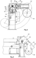
- FIG. 12 now shows a sectional view of the adjustment device 20.
- the adjustment device 20 has a second drive device 22 which is operatively connected via a clutch 24 to a worm shaft 26 of a worm gear 28.
- the worm gear 28 has a worm wheel 30 which is mounted on the storage flap shaft 18 in a rotationally fixed manner.
- the worm shaft 26 is rotatably mounted in the transmission housing part 10 , with the transmission housing part 10 being rotatably mounted on the storage flap shaft 18 .
- the worm wheel 30 has a continuous, part-circular groove element 32 through which a pin element 34 fixedly connected to the transmission housing part 10 engages or penetrates.
- the angle of the pitch circle of the groove element 32 is selected to be larger than the adjustment angle of the adjustment device 20 explained below.
- the angle of the reference circle is approximately 140°.
- the groove element 32 with the engaging pin element 34 is used for an unwanted adjustment of the adjustment device 20 beyond the adjustment angle.
- the groove element 32 has a first end 36 and a second end 38 .
- a weight element 40 is assigned to the transmission housing part 10, which can be operated via a lever arrangement 42 (see figure 3 ) is connected to the transmission housing part 10.
- the maximum opening angle of the storage flap 16 is limited by a stop element, not shown in detail, which interacts with the storage flap shaft 18 .
- the second drive device 22 is now actuated for presetting.
- the storage flap 16 closes the outlet opening 14 at this moment and cannot deviate in this direction, so that the storage flap shaft 18 and thus the worm wheel 30 do not move.
- the worm shaft 26 and thus the gear housing part 10 move consequently in Clockwise around the worm wheel 26, whereby the weight member 40 is adjusted on the indicated circular path.
- a variable lever is assigned to the force of weight acting vertically downwards, which allows a variable moment to act on the flapper shaft 18 and thus a variable force to act on the flapper 16 .
- the preset position is selected in such a way that a large lever acts on the weight member 40 and thus a large force acts on the storage flap 16, as a result of which a bulk density can be achieved which is approximately 90% of the maximum compression,
- the entire adjustment device 20 consisting of the gear 28, the gear housing part 10, the weight member 40 and the second drive device 22 is rotated counterclockwise.
- the dynamic pressure on the flap 16 will increase or decrease, which is then compensated for by an automatic shifting of the weight element 40 .
- the entire adjustment device 20 thus forms the mechanically acting, automatic dynamic pressure adjustment device.
- the setting device 20 will pivot back into the preset position due to the weight of the weight member 40 .
- FIG 3 now shows the adjustment device 20 in a side view, the adjustment device being pivoted through an angle of approx. 45% and thus causing a compression of approx. 45% of the maximum compression.
- the lever element 42 via which the Weight member 40 is articulated on the transmission housing part 10.
- a sensor element for example a Hall sensor, is denoted by 44 here, which detects the angle of rotation of the baffle plate shaft 18 and thus monitors the opening angle of the baffle flap 16 .
- the drive device 22 is designed as a stepper motor.
Landscapes
- Engineering & Computer Science (AREA)
- Mechanical Engineering (AREA)
- Chemical & Material Sciences (AREA)
- Chemical Kinetics & Catalysis (AREA)
- Gear Transmission (AREA)
- Tea And Coffee (AREA)
- Basic Packing Technique (AREA)
- Auxiliary Devices For And Details Of Packaging Control (AREA)
- Compressor (AREA)
- Compressors, Vaccum Pumps And Other Relevant Systems (AREA)
- Mechanically-Actuated Valves (AREA)
Description
- Die Erfindung betrifft eine Verdichteranordnung zum automatischen Verdichten von Mahlkaffee mit einem ersten Gehäuse, das eine Ein- und Auslassöffnung aufweist, wobei in dem Gehäuse Förder- und Verdichterorgane vorgesehen sind, die mittels mindestens einer ersten Antriebsvorrichtung antreibbar sind, wobei die Auslassvorrichtung eine Stauklappe aufweist, die der Einstellung der Schüttdichte des Mahlkaffees dient, wobei eine Einstellvorrichtung vorgesehen ist, über die eine Voreinstellung der Schüttdichte einstellbar ist, wobei die Einstellvorrichtung eine zweite Antriebsvorrichtung aufweist.
- Grundsätzlich sind Verdichteranordnungen bzw. Pressenanordnung mit einer Voreinstellungsmöglichkeit für das zu verdichtende Schüttgut bzw. das zu verpressende Pressgut beispielsweise aus der
DE 298 20 464 U1 , derDE 580 974 C , derUS 1,941,573 und derUS 1 835 789 A bekannt. - Dahingegen beschreibt die
DE 197 18 455 A1 eine Verdichteranordnung mit einer Messeinrichtung, bei der der aus einem Mahlwerk stammende Mahlkaffee entsprechend den Vorgaben hinsichtlich Füllgewicht und Füllvolumen verdichtet wird. Um dies zu erreichen, muss der abzufüllende Mahlkaffee eine bestimmte Schüttdichte (Gramm pro cm3) aufweisen. Hierzu besitzt die Verdichteranordnung gemäß derDE 197 18 455 A1 eine Stauklappe an einer Auslassöffnung der Verdichteranordnung, die entsprechend der gewünschten Schüttdichte zwischen 0° und 90° geöffnet verstellt werden kann. Im Bereich der Auslassöffnung ist die Messeinrichtung für die Schüttdichte bzw. den Kompaktierungsgrad vorgesehen, so dass eine Regelung über eine Verstellung der Stauklappe ermöglicht ist. Darüber hinaus ist aus derDE 197 23 761 A1 eine Verdichteranordnung bekannt, die eine Einstellvorrichtung mit einer zweiten Antriebsvorrichtung aufweist, um einen bestimmten Andruck ein zu stellen. Jedoch wird zum Ausgleich von Druckveränderungen, wie in der vorgenanntenDE 197 18 455 A1 , der Druck gemessen und über eine Regelung die erste Antriebseinrichtung angepasst. - Das Dokument
DE 197 23 761 A1 offenbart eine Verdichteranordnung gemäß dem Oberbegriff des Anspruchs 1. - Die Anordnung der Messeinrichtung im Bereich der Auslassöffnung ist kompliziert und daher teuer und störanfällig. Darüber hinaus können plötzliche Mahlkaffeemengenschwankungen im Verdichter, die beispielsweise durch abrutschenden Mahlkaffee von den Seitenwänden in den Verdichtertrog entstehen, nicht ausgeglichen werden, was zu Überlastschäden in der ersten Antriebseinrichtung führen kann.
- Der Erfindung liegt daher die Aufgabe zugrunde, eine Verdichteranordnung zum automatischen Verdichten von Mahlkaffee bereit zu stellen, die die oben genannten Nachtelle auf kostengünstige und einfache Weise vermeidet.
- Diese Aufgabe wird dadurch gelöst, dass die zweite Antriebsvorrichtung mit einem Getriebe wirkverbunden ist, das mit einer Stauklappenwelle wirkverbunden ist, an der die Stauklappe angeordnet ist, derart, dass das Getriebe Mittel aufweist, die eine Begrenzung des Öffnungswinkels der Stauklappe ermöglichen und wobei eine automatische Staudruckanpassungseinrichtung vorgesehen ist, die, im Falle eines an der Stauklappe wirkenden höheren bzw., niedrigeren Staudruckes, eine Vergrößerung bzw, Verringerung des voreingestellten Öffnungswinkels ermöglicht, wobei das Getriebe ein Schneckengetriebe ist, das eine Schneckenwelle und ein Schneckenrad aufweist, wobei ein Getriebegehäuseteil vorgesehen ist, das drehbar auf der Stauklappenwelle gelagert ist und in dem die Schneckenwelle drehfest auf der Stauklappenwelle gelagert ist, derart, dass eine Drehung der Schneckenwelle eine Drehung des Getriebegenhäusteils um das Schneckenrad ermöglicht und wobei dem Getriebegehäuseteil ein definiertes Gewicht zugeordnet ist, dass die Voreinstellung des gewünschten Öffnungswinkels ermöglicht. Die Stauklappe ist also nicht mehr in einem bestimmten Winkel voreingestellt, sondern sie ist bis zu einem bestimmten, vordefinierten Öffnungswinkel schwenkbar. Durch die mechanische Staudruckanpassungseinrichtung, kann ein kurzfristiges Überschreiten oder Unterschreiten der Mahlkaffeemenge und damit eine Erhöhung oder Verringerung des auf die Stauklappe wirkenden Staudruckes auf einfache Weise abgefangen werden. Die Stauklappe kann dann wieder in den voreingestellten Öffnungswinkel zurückschwenken. Folglich ist auch keine Messeinrichtung im Bereich der Auslassöffnung mehr erforderlich. Durch dioe besondere Ausbildung des Getriebes wird auf besonders einfache Art und Weise einerseits eine Voreinstellung des maximalen Öffnungswinkels der Stauklappe vorgenommen, wobei die mechanische Staudruckanpassungseinrichtung durch das Getriebe und das Getriebegehäuseteil mit dem zugeordneten Gewicht wahrgenommen wird, derart, dass im Falle einer erforderlichen Anpassung des voreingestellten Öffnungswinkels die Stauklappenwelle über das Getriebe mit dem Getriebegehäuseteil verschwenken kann. Aufgrund der Gewichtseinstellung ist die gewünschte Schüttdichte erreichbar. Es sei darauf hingewiesen, dass unter dem Begriff "voreingestellter Öffnungswinkel" der Öffnungswinkel verstanden wird, den die Stauklappe bei Anliegen eines Staudruckes einnimmt. Im ausgeschalteten Zustand der Verdichteranordnung ist die Stauklappe also geschlossen. Auf diese Weise ist es natürlich möglich vor dem Hintergrund der maschinenspezifischen Daten der jeweiligen Verdichteranordnung, wie z.B. Leistung, Dimensionierung, etc. Gewichte einem Öffnungswinkel und damit einer gewünschten Schüttdichte als Daten zu hinterlegen und somit eine einfache Einstellung zu gewährleisten.
- In einer weiteren vorteilhaften Ausführungsform ist ein Gewichtsorgan vorgesehen, das über eine Hebelanordnung mit dem Getriebegehäuseteil verbunden ist. Durch eine einfache Verdrehung des Hebels wirkt ein anderes Moment auf die Stauklappenwelle, wodurch auch eine andere Kraft auf die Stauklappe wirkt, wodurch die Stauklappe aufgrund des anliegenden Staudruckes weiter oder geringer öffnet. Hierbei ist es denkbar ist, dass das Gewichtsorgan einstellbar an der Hebelanordnung angeordnet ist und auf diese Weise die Verdichteranordnung eine größere Flexibilität aufweist und der Einstellbereich vergrößert ist.
- Dadurch, dass das Schneckenrad ein teilkreisförmiges Nutorgan aufweisen kann, in das ein Stiftorgan eingreift, das wiederum im Getriebegehäuseteil gelagert ist, derart, dass die Drehung des Getriebegehäuseteils während der Voreinstellung durch ein erstes und zweites Ende des Nutorgans begrenzt ist, wird auf einfache Weise eine ungewollte Verstellung, beispielsweise aufgrund eines Fehlers der zweiten Antriebseinrichtung verhindert.
- In einer vorteilhaften Ausführungsform kann der maximale Öffnungswinkel der Stauklappe durch ein Anschlagelement begrenzt sein, das mit der Stauklappenwelle zusammenwirkt.
- In vorteilhafter Weise ist die zweite Antriebsvorrichtung über eine Kupplung mit dem Getriebe wirkverbunden, wobei die Kupplung als lösbare Kupplung ausgeführt sein kann.
- Desweiteren kann in vorteilhafter Weise die zweite Antriebsvorrichtung eine Elektromaschine sein, insbesondere ein Steppermotor. Um eine einfache Darstellung des voreingestellten Öffnungswinkels, beispielsweise in einem Display, zu ermöglichen, kann die Einstellvorrichtung ein Sensororgan zur Überwachung der Stellung der Stauklappenwelle aufweisen. Dies kann direkt oder indirekt, beispielsweise über eine Phasenverschiebung des Getriebes durchgeführt werden.
- Die Erfindung wird anhand einer Zeichnung näher erläutert. Hierbei zeigt:
-
Figur 1 eine perspektivische Anordnung der erfindungsgemäßen Verdichteranordnung, -
Figur 2 eine teilweise geschnittene Seitenansicht einer Einstellvorrichtung der Verdichteranordnung ausFigur 1 in einer ersten Einstellposition, und -
Figur 3 die Einstellvorrichtung der Verdichteranordnung ausFigur 1 in einer zweiten Position. -
Figur 1 zeigt in einer perspektivischen Ansicht eine erfindungsgemäße Verdichteranordnung 2 zum automatischen Verdichten von Mahlkaffee. Die Verdichteranordnung 2 weist ein Gehäuse 4 auf, das im Wesentlichen sich aus mehreren Gehäuseteilen 6, 8, 10, die wiederum mehrteilig ausgeführt sein können, zusammensetzt. So ist das erste Gehäuseteil 6 trogförmig ausgebildet und weist eine Einlassöffnung 12 auf, die auf bekannte Weise sich an ein nicht weiter dargestelltes Mahlwerk anschließt. In dem Gehäuseteil 6 kann eine hier nicht weiter dargestellte Förderschnecke angeordnet sein, die den Mahlkaffee weiter zum zweiten Gehäuseteil 8 fördert, in dem wiederum ein nicht weiter dargestellter Turbomischer zum homogenen Verteilen von Kaffeehäutchen und zum Verdichten des Mahlkaffees angeordnet ist. Die Förderschnecke und der Turbomischer sind auf bekannte Weise mit einer nicht weiter dargestellten ersten Antriebsvorrichtung verbunden. Der Mahlkaffee wird durch den Turbomischer in Richtung einer im zweiten Gehäuseteil 8 angeordneten Auslassöffnung 14 hin verdichtet, an die sich eine Stauklappe 16 anschließt. Die Stauklappe 16 ist an eine Stauklappenwelle 18 angelenkt, die wiederum mit einer Einstellvorrichtung 20 wirkverbunden ist, die als drittes Gehäuseteil 10 ein Getriebegehäuseteil besitzt. Im nicht betätigten Zustand der Verdichteranordnung verschließt die Stauklappe 16 die Auslassöffnung 14. Wie unten zu denFiguren 2 bis 3 noch näher erläutert, ermöglicht die Einstellvorrichtung 20 eine Voreinstellung des Öffnungswinkels der Stauklappe 16, wodurch eine Einstellung der Schüttdichte des Mahlkaffees ermöglicht wird. -
Figur 2 zeigt nun eine Schnittansicht der Einstellvorrichtung 20. Die Einstellvorrichtung 20 weist eine zweite Antriebsvorrichtung 22 auf, die über eine Kupplung 24 mit einer Schneckenwelle 26 eines Schneckengetriebes 28 wirkverbunden ist. Das Schneckengetriebe 28 weist auf bekannte Weise ein Schneckenrad 30 auf, das auf der Stauklappenwelle 18 drehfest gelagert ist. Die Schneckenwelle 26 ist seinerseits drehbar im Getriebegehäuseteil 10 gelagert, wobei das Getriebegehäuseteil 10 drehbar auf der Stauklappenwelle 18 gelagert ist. Desweiteren weist das Schneckenrad 30 ein durchgehendes, teilkreisförmiges Nutorgan 32 auf, durch das ein fest mit dem Getriebegehäuseteil 10 verbundenes Stiftorgan 34 eingreift, bzw. hindurchgreift. Der Winkel des Teilkreises des Nutorgans 32 ist größer als der nachfolgend erläuterte Verstellwinkel der Einstellvorrichtung 20 gewählt. Im vorliegenden Fall beträgt der Winkel des Teilkreises ca. 140°. Das Nutorgan 32 mit dem eingreifenden Stiftorgan 34 dient einer nicht gewollten Verstellung der Einstellvorrichtung 20 über den Verstellwinkel hinaus. Hierzu weist das Nutorgan 32 ein erstes Ende 36 und ein zweites Ende 38 auf. Dem Getriebegehäuseteil 10 ist ein Gewichtsorgan 40 zugeordnet, das über eine Hebelanordnung 42 (siehe hierzuFigur 3 ) mit dem Getriebegehäuseteil 10 verbunden ist. Desweiteren wird der maximale Öffnungswinkel der Stauklappe 16 durch ein nicht weiter dargestelltes Anschlagelement begrenzt, das mit der Stauklappenwelle 18 zusammenwirkt. - Zu Voreinstellung wird nun die zweite Antriebsvorrichtung 22 betätigt. Die Stauklappe 16 verschließt in diesem Moment die Auslassöffnung 14 und kann in diese Richtung nicht ausweichen, so dass die Stauklappenwelle 18 und somit das Schneckenrad 30 sich nicht bewegen. Die Schneckenwelle 26 und somit das Getriebegehäuseteil 10 bewegen sich folglich im Uhrzeigersinn um das Schneckenrad 26, wodurch das Gewichtsorgan 40 auf der angedeuteten Kreisbahn verstellt wird. Der senkrecht nach unten wirkenden Gewichtskraft ist hierdurch ein veränderlicher Hebel zugeordnet, der ein veränderliches Moment auf die Stauklappenwelle 18 wirken lässt und damit eine veränderliche Kraft auf die Stauklappe 16 wirken lässt. In
Figur 2 ist die voreingestellte Position derart gewählt, dass ein großer Hebel auf das Gewichtsorgan 40 wirkt und somit eine große Kraft auf die Stauklappe 16 wirkt, wodurch eine Schüttdichte erreichbar ist, die ca. 90% der maximalen Verdichtung beträgt, - Wird nun die erste Antriebsvorrichtung der Verdichteranordnung 2 in Betrieb gesetzt und der Mahlkaffee verdichtet in Richtung der Auslassöffnung 14 gefördert, wird ein Staudruck im Bereich der Auslassöffnung 14 aufgebaut, der schließlich dazu führt, dass sich die Stauklappe 16 öffnet, wodurch die Stauklappenwelle 18 das Schneckenrad 30 dreht und somit die gesamte Einstellvorrichtung 20 bestehend aus dem Getriebe 28, dem Getriebegehäuseteil 10, dem Gewichtsorgan 40 sowie der zweiten Antriebsvorrichtung 22 gegen den Uhrzeigersinn gedreht wird. Bei kurzfristigen Schwankungen der Mahlkaffeemenge, wird sich der Staudruck auf die Stauklappe 16 erhöhen oder verringern was dann durch eine automatische Verlagerung des Gewichtsorgans 40 ausgeglichen wird. Im vorliegenden Ausführungsbeispiel bildet somit die gesamte Einstellvorrichtung 20 die mechanisch wirkende, automatische Staudruckanpassungseinrichtung.
- Danach wird die Einstellvorrichtung 20 aufgrund der Gewichtskraft des Gewichtsorgans 40 wieder in die voreingestellte Position zurückschwenken.
-
Figur 3 zeigt nun die Einstellvorrichtung 20 in einer Seitenansicht, wobei die Einstellvorrichtung um einen Winkel von ca. 45% verschwenkt ist und damit eine Verdichtung von ca. 45% der maximalen Verdichtung bewirkt. Deutlich zu erkennen ist hier auch das Hebelorgan 42, über das das Gewichtsorgan 40 an dem Getriebegehäuseteil 10 angelenkt ist. Mit 44 ist hier ein Sensororgan, beispielsweise ein Hallsensor, bezeichnet, das den Verdrehwinkel der Stauplattenwelle 18 detektiert und somit den Öffnungswinkel der Stauklappe 16 überwacht. Die Antriebsvorrichtung 22 ist im vorliegenden Ausführungsbeispiel als Steppermotor ausgeführt. - Es sollte deutlich sein, dass insbesondere hinsichtlich der Ausführung des Getriebes viele Austührungsmöglichkeiten darstellbar sind, insoweit sie den Schutzbereich der Ansprüchen allen.
Claims (9)
- Verdichteranordung zum automatischen Verdichten von Mahlkaffee mit einem ersten Gehäuse (4), das eine Einlass- und Auslassöffnung (12, 14) aufweist, wobei in dem Gehäuse (4) Förder- und Verdichterorgane vorgesehen sind, die mittels mindestens einer ersten Antriebsvorrichtung antreibbar sind, wobei die Auslassöffnung (14) eine Stauklappe (16) aufweist, die der Einstellung der Schüttdichte des Mahlkaffees dient, wobei eine Einstellvorrichtung (20) vorgesehen ist, über die eine Voreinstellung der Schüttdichte einstellbar ist, wobei die Einstellvorrichtung (20) eine zweite Antriebsvorrichtung (22) aufweist,dadurch gekennzeichnet, dassdie zweite Antriebsvorrichtung (22) mit einem Getriebe (28) wirkverbunden ist, das mit einer Stauklappenwelle (18) wirkverbunden ist, an der die Stauklappe (16) angeordnet ist, derart, dass das Getriebe (28) Mittel (30, 32, 34, 36, 38) aufweist, die eine Begrenzung des Öffnungswinkels der Stauklappe (16) ermöglichen und wobei eine automatische Staudruckanpassungseinrichtung (10, 40, 42) vorgesehen ist, die, im Falle eines an der Stauklappe (16) wirkenden höheren bzw. niedrigeren Staudruckes, eine Vergrößerung bzw. Verringerung des voreingestellten Öffnungswinkels ermöglicht, wobei das Getriebe (28) ein Schneckengetriebe ist, das eine Schneckenwelle (26) und ein Schneckenrad (30) aufweist, wobei ein Getriebegehäuseteil (10) vorgesehen ist, das drehbar auf der Stauklappenwelle (18) gelagert ist und in dem die Schneckenwelle (26) drehfest auf der Stauklappenwelle (18) gelagert ist, derart, dass eine Drehung der Schneckenwelle eine Drehung des Getriebegehäuseteils (10) um das Schneckenrad (30) ermöglicht und wobei dem Getriebegehäuseteil (10) ein definiertes Gewicht zugeordnet ist, dass die Voreinstellung des gewünschten Öffnungswinkels ermöglicht.
- Verdichteranordnung nach Anspruch 1, dadurch gekennzeichnet, dass ein Gewichtsorgan (40) vorgesehen ist, das über eine Hebelanordnung (42) mit dem Getriebegehäuseteil (10) verbunden ist.
- Verdichteranordnung nach Anspruch 2, dadurch gekennzeichnet, dass das Gewichtsorgan (40) einstellbar an der Hebelanordnung (42) angeordnet ist.
- Verdichteranordnung nach einem der vorhergehenden Ansprüche, dadurch gekennzeichnet, dass das Schneckenrad (30) ein teilkreisförmiges Nutorgan (32) aufweist, in das ein Stiftorgan (34) eingreift, das wiederum im Getriebegehäuseteil (10) gelagert ist, derart, dass die Drehung des Getriebegehäuseteils (10) während der Voreinstellung durch ein erstes und zweites Ende (36, 38) des Nutorgans (32) begrenzt ist.
- Verdichteranordnung nach einem der vorhergehenden Ansprüche, dadurch gekennzeichnet, dass der maximale Öffnungswinkel der Stauklappe (16) durch ein Anschlagelement begrenzt ist, das mit der Stauklappenwelle (18) zusammenwirkt.
- Verdichteranordnung nach einem der vorhergehenden Ansprüche, dadurch gekennzeichnet, dass die zweite Antriebsvorrichtung (22) über eine Kupplung (24) mit dem Getriebe (28) wirkverbunden ist.
- Verdichteranordnung nach Anspruch 6, dadurch gekennzeichnet, dass die Kupplung (24) eine lösbare Kupplung ist.
- Verdichteranordnung nach einem der vorhergehenden Ansprüche, dadurch gekennzeichnet, dass die zweite Antriebsvorrichtung (22) eine Elektromaschine, insbesondere ein Steppermotor, ist.
- Verdichteranordnung nach einem der vorhergehenden Ansprüche, dadurch gekennzeichnet, dass die Einstellvorrichtung (20) ein Sensororgan (44) zur Überwachung der Stellung der Stauklappenwelle (18) aufweist.
Applications Claiming Priority (2)
| Application Number | Priority Date | Filing Date | Title |
|---|---|---|---|
| DE102014106407.0A DE102014106407B4 (de) | 2014-05-07 | 2014-05-07 | Verdichteranordnung zum automatischen Verdichten von Mahlkaffee |
| PCT/EP2015/055031 WO2015169483A1 (de) | 2014-05-07 | 2015-03-11 | Verdichteranordnung zum automatischen verdichten von mahlkaffee |
Publications (2)
| Publication Number | Publication Date |
|---|---|
| EP3140109A1 EP3140109A1 (de) | 2017-03-15 |
| EP3140109B1 true EP3140109B1 (de) | 2022-02-09 |
Family
ID=52706143
Family Applications (1)
| Application Number | Title | Priority Date | Filing Date |
|---|---|---|---|
| EP15711446.3A Active EP3140109B1 (de) | 2014-05-07 | 2015-03-11 | Verdichteranordnung zum automatischen verdichten von mahlkaffee |
Country Status (10)
| Country | Link |
|---|---|
| US (1) | US10569490B2 (de) |
| EP (1) | EP3140109B1 (de) |
| JP (1) | JP6410843B2 (de) |
| KR (1) | KR101902676B1 (de) |
| CN (1) | CN106457721B (de) |
| AU (1) | AU2015258065B2 (de) |
| BR (1) | BR112016021543B1 (de) |
| CA (1) | CA2940786C (de) |
| DE (1) | DE102014106407B4 (de) |
| WO (1) | WO2015169483A1 (de) |
Citations (1)
| Publication number | Priority date | Publication date | Assignee | Title |
|---|---|---|---|---|
| US1941573A (en) * | 1932-09-20 | 1934-01-02 | Fuller Co | Conveying system |
Family Cites Families (19)
| Publication number | Priority date | Publication date | Assignee | Title |
|---|---|---|---|---|
| US1752054A (en) * | 1925-05-28 | 1930-03-25 | Anderson Co V D | Press |
| DE580974C (de) | 1927-04-06 | 1933-07-24 | V D Anderson Company | Schneckenpresse fuer OElfruechte u. dgl. |
| US1835789A (en) * | 1928-01-30 | 1931-12-08 | American Voith Contact Co | Screw press |
| US2178714A (en) * | 1936-03-05 | 1939-11-07 | Anderson Co V D | Press |
| FR1180083A (fr) * | 1956-07-11 | 1959-06-01 | Stamicarbon | Appareil de distribution continue |
| GB1338114A (en) * | 1971-05-12 | 1973-11-21 | Louise Gmbh Maschbau | Apparatus for emptying or removing bulk material from containers bunkers and the like in which a positive or negative pressure prevails with respect to atmosphere pressure |
| FR2191471A5 (de) | 1972-06-28 | 1974-02-01 | Somavi | |
| US4279556A (en) * | 1980-01-11 | 1981-07-21 | Ronning Engineering Company, Inc. | Auger airlock assembly having product cutting knife |
| CH662995A5 (de) * | 1984-03-30 | 1987-11-13 | Sig Schweiz Industrieges | Einrichtung zum dosieren von schuettgut. |
| DE4232449B4 (de) * | 1992-09-28 | 2005-06-23 | Fan Separator Gmbh | Preßschneckenseparator mit Ausstoßregler |
| US5464120A (en) * | 1994-05-27 | 1995-11-07 | Flurry International, Inc. | Method and apparatus for frozen dessert dispensing |
| DE29502986U1 (de) * | 1995-02-22 | 1996-03-21 | Probat-Werke von Gimborn Maschinenfabrik GmbH, 46446 Emmerich | Vorrichtung zum Dosieren und Verdichten von körnigem Gut |
| US5653879A (en) * | 1996-02-16 | 1997-08-05 | Schroeder; Vern | Liquid and solid separator |
| DE29607846U1 (de) | 1996-04-30 | 1996-07-25 | Neuhaus Neotec Maschinen- und Anlagenbau GmbH, 21465 Reinbek | Vorrichtung zum Dosieren von Mahlkaffee in Kaffeeverpackungen |
| DE19723761A1 (de) | 1996-06-26 | 1998-01-02 | Buehler Gmbh | Verfahren zum Kompaktieren von körnigem oder pulverigen Gut und Vorrichtung zur Durchführung des Verfahrens |
| DE29820464U1 (de) | 1998-11-16 | 1999-01-28 | Pro-Technik-Konstruktionen GmbH, 86159 Augsburg | Schneckenpresse |
| DE20210004U1 (de) * | 2002-06-28 | 2003-11-20 | C.M.S. S.p.A., Marano sul Panaro, Modena | Vorrichtung zum Verdichten von Material |
| ITBO20050693A1 (it) * | 2005-11-15 | 2007-05-16 | Cms Spa | Apparato per la regolazione automatica dell'azione dei mezzi di strozzatura posti sulla bocca di scarico di presse a coclea, ad esempio del tipo impiegato per la compattazione dei rifiuti |
| CN202953191U (zh) | 2012-11-27 | 2013-05-29 | 福建铁拓机械有限公司 | 一种新型阀口干粉砂浆包装机 |
-
2014
- 2014-05-07 DE DE102014106407.0A patent/DE102014106407B4/de active Active
-
2015
- 2015-03-11 EP EP15711446.3A patent/EP3140109B1/de active Active
- 2015-03-11 AU AU2015258065A patent/AU2015258065B2/en active Active
- 2015-03-11 US US15/308,609 patent/US10569490B2/en active Active
- 2015-03-11 WO PCT/EP2015/055031 patent/WO2015169483A1/de not_active Ceased
- 2015-03-11 BR BR112016021543-5A patent/BR112016021543B1/pt active IP Right Grant
- 2015-03-11 CN CN201580020222.2A patent/CN106457721B/zh active Active
- 2015-03-11 CA CA2940786A patent/CA2940786C/en active Active
- 2015-03-11 KR KR1020167034118A patent/KR101902676B1/ko active Active
- 2015-03-11 JP JP2016566989A patent/JP6410843B2/ja active Active
Patent Citations (1)
| Publication number | Priority date | Publication date | Assignee | Title |
|---|---|---|---|---|
| US1941573A (en) * | 1932-09-20 | 1934-01-02 | Fuller Co | Conveying system |
Also Published As
| Publication number | Publication date |
|---|---|
| BR112016021543B1 (pt) | 2021-12-21 |
| CA2940786C (en) | 2019-05-21 |
| CN106457721B (zh) | 2018-12-25 |
| EP3140109A1 (de) | 2017-03-15 |
| US20170182725A1 (en) | 2017-06-29 |
| JP6410843B2 (ja) | 2018-10-24 |
| BR112016021543A2 (pt) | 2017-08-15 |
| KR20170026351A (ko) | 2017-03-08 |
| AU2015258065A1 (en) | 2016-09-15 |
| AU2015258065B2 (en) | 2017-11-02 |
| DE102014106407A1 (de) | 2015-11-12 |
| KR101902676B1 (ko) | 2018-09-28 |
| CN106457721A (zh) | 2017-02-22 |
| US10569490B2 (en) | 2020-02-25 |
| DE102014106407B4 (de) | 2016-03-10 |
| WO2015169483A1 (de) | 2015-11-12 |
| JP2017520480A (ja) | 2017-07-27 |
| CA2940786A1 (en) | 2015-11-12 |
Similar Documents
| Publication | Publication Date | Title |
|---|---|---|
| AT505126B1 (de) | Klappenantriebssystem | |
| DE102011055438B4 (de) | Verstellvorrichtung für einen Kraftfahrzeugsitz | |
| WO2008135299A1 (de) | Klappenbeschlag | |
| WO1986001128A1 (fr) | Dispositif de reglage de l'ecartement de mouture pour moulins a cylindres | |
| EP3718446A1 (de) | Einstelleinrichtung zum einstellen des mahlgrads eines mahlwerks | |
| DE1755976A1 (de) | Hydrodynamische Bremse,insbesondere fuer Kraftfahrzeuge | |
| DE19700588A1 (de) | Hydraulisches Überlastventilsystem für eine mechanische Presse | |
| AT514426B1 (de) | Handlingvorrichtung oder Formgebungsmaschine | |
| EP2608708B1 (de) | Küchengerät | |
| DE202020102934U1 (de) | Ausgabeeinheit für Kolben-Espressomaschinen | |
| DE102014106407B4 (de) | Verdichteranordnung zum automatischen Verdichten von Mahlkaffee | |
| EP4059676B1 (de) | Schneidemaschine mit messertiefgangeinstellung | |
| EP3388716A1 (de) | Schliessvorrichtung | |
| WO2015176915A1 (de) | Brecher zum zerkleinern von brechgut, sowie verfahren zum betreiben eines brechers | |
| EP2983876A1 (de) | Fahrmischer für beton, mörtel oder dergleichen fliessfähigen materialien | |
| DE2400987A1 (de) | Hubwerk mit motorantrieb fuer ein bewegliches teil, insbesondere fuer ein tor | |
| DE102010037935B4 (de) | Schleuderdüngerstreuer | |
| DE3231496C2 (de) | Windkraftmaschine mit selbsttätig wirkender Sturmsicherung | |
| EP3623210B1 (de) | Fahrzeugsitz | |
| DE3234217C2 (de) | ||
| DE102007053639B4 (de) | Vorrichtung zum Zerkleinern von Lebensmitteln | |
| WO2011042141A1 (de) | Schneideinrichtung für eine strangmaschine der tabak verarbeitenden industrie und verfahren zum verstellen der schneideinrichtung | |
| EP4488197A1 (de) | Trittbrett und verfahren zum justieren eines trittbretts | |
| EP1441153B1 (de) | Miststreuwagen mit einer Getriebesteuerung | |
| DE202006016988U1 (de) | Tower-Lüfter |
Legal Events
| Date | Code | Title | Description |
|---|---|---|---|
| STAA | Information on the status of an ep patent application or granted ep patent |
Free format text: STATUS: THE INTERNATIONAL PUBLICATION HAS BEEN MADE |
|
| PUAI | Public reference made under article 153(3) epc to a published international application that has entered the european phase |
Free format text: ORIGINAL CODE: 0009012 |
|
| STAA | Information on the status of an ep patent application or granted ep patent |
Free format text: STATUS: REQUEST FOR EXAMINATION WAS MADE |
|
| 17P | Request for examination filed |
Effective date: 20160916 |
|
| AK | Designated contracting states |
Kind code of ref document: A1 Designated state(s): AL AT BE BG CH CY CZ DE DK EE ES FI FR GB GR HR HU IE IS IT LI LT LU LV MC MK MT NL NO PL PT RO RS SE SI SK SM TR |
|
| AX | Request for extension of the european patent |
Extension state: BA ME |
|
| DAV | Request for validation of the european patent (deleted) | ||
| DAX | Request for extension of the european patent (deleted) | ||
| STAA | Information on the status of an ep patent application or granted ep patent |
Free format text: STATUS: EXAMINATION IS IN PROGRESS |
|
| 17Q | First examination report despatched |
Effective date: 20191112 |
|
| GRAP | Despatch of communication of intention to grant a patent |
Free format text: ORIGINAL CODE: EPIDOSNIGR1 |
|
| STAA | Information on the status of an ep patent application or granted ep patent |
Free format text: STATUS: GRANT OF PATENT IS INTENDED |
|
| GRAJ | Information related to disapproval of communication of intention to grant by the applicant or resumption of examination proceedings by the epo deleted |
Free format text: ORIGINAL CODE: EPIDOSDIGR1 |
|
| GRAP | Despatch of communication of intention to grant a patent |
Free format text: ORIGINAL CODE: EPIDOSNIGR1 |
|
| INTG | Intention to grant announced |
Effective date: 20210902 |
|
| INTG | Intention to grant announced |
Effective date: 20210902 |
|
| INTG | Intention to grant announced |
Effective date: 20210915 |
|
| GRAS | Grant fee paid |
Free format text: ORIGINAL CODE: EPIDOSNIGR3 |
|
| GRAA | (expected) grant |
Free format text: ORIGINAL CODE: 0009210 |
|
| STAA | Information on the status of an ep patent application or granted ep patent |
Free format text: STATUS: THE PATENT HAS BEEN GRANTED |
|
| AK | Designated contracting states |
Kind code of ref document: B1 Designated state(s): AL AT BE BG CH CY CZ DE DK EE ES FI FR GB GR HR HU IE IS IT LI LT LU LV MC MK MT NL NO PL PT RO RS SE SI SK SM TR |
|
| REG | Reference to a national code |
Ref country code: GB Ref legal event code: FG4D Free format text: NOT ENGLISH |
|
| REG | Reference to a national code |
Ref country code: CH Ref legal event code: EP Ref country code: AT Ref legal event code: REF Ref document number: 1467253 Country of ref document: AT Kind code of ref document: T Effective date: 20220215 |
|
| REG | Reference to a national code |
Ref country code: DE Ref legal event code: R096 Ref document number: 502015015622 Country of ref document: DE |
|
| REG | Reference to a national code |
Ref country code: IE Ref legal event code: FG4D Free format text: LANGUAGE OF EP DOCUMENT: GERMAN |
|
| REG | Reference to a national code |
Ref country code: LT Ref legal event code: MG9D |
|
| REG | Reference to a national code |
Ref country code: NL Ref legal event code: MP Effective date: 20220209 |
|
| PG25 | Lapsed in a contracting state [announced via postgrant information from national office to epo] |
Ref country code: SE Free format text: LAPSE BECAUSE OF FAILURE TO SUBMIT A TRANSLATION OF THE DESCRIPTION OR TO PAY THE FEE WITHIN THE PRESCRIBED TIME-LIMIT Effective date: 20220209 Ref country code: RS Free format text: LAPSE BECAUSE OF FAILURE TO SUBMIT A TRANSLATION OF THE DESCRIPTION OR TO PAY THE FEE WITHIN THE PRESCRIBED TIME-LIMIT Effective date: 20220209 Ref country code: PT Free format text: LAPSE BECAUSE OF FAILURE TO SUBMIT A TRANSLATION OF THE DESCRIPTION OR TO PAY THE FEE WITHIN THE PRESCRIBED TIME-LIMIT Effective date: 20220609 Ref country code: NO Free format text: LAPSE BECAUSE OF FAILURE TO SUBMIT A TRANSLATION OF THE DESCRIPTION OR TO PAY THE FEE WITHIN THE PRESCRIBED TIME-LIMIT Effective date: 20220509 Ref country code: NL Free format text: LAPSE BECAUSE OF FAILURE TO SUBMIT A TRANSLATION OF THE DESCRIPTION OR TO PAY THE FEE WITHIN THE PRESCRIBED TIME-LIMIT Effective date: 20220209 Ref country code: LT Free format text: LAPSE BECAUSE OF FAILURE TO SUBMIT A TRANSLATION OF THE DESCRIPTION OR TO PAY THE FEE WITHIN THE PRESCRIBED TIME-LIMIT Effective date: 20220209 Ref country code: HR Free format text: LAPSE BECAUSE OF FAILURE TO SUBMIT A TRANSLATION OF THE DESCRIPTION OR TO PAY THE FEE WITHIN THE PRESCRIBED TIME-LIMIT Effective date: 20220209 Ref country code: ES Free format text: LAPSE BECAUSE OF FAILURE TO SUBMIT A TRANSLATION OF THE DESCRIPTION OR TO PAY THE FEE WITHIN THE PRESCRIBED TIME-LIMIT Effective date: 20220209 Ref country code: BG Free format text: LAPSE BECAUSE OF FAILURE TO SUBMIT A TRANSLATION OF THE DESCRIPTION OR TO PAY THE FEE WITHIN THE PRESCRIBED TIME-LIMIT Effective date: 20220509 |
|
| PG25 | Lapsed in a contracting state [announced via postgrant information from national office to epo] |
Ref country code: PL Free format text: LAPSE BECAUSE OF FAILURE TO SUBMIT A TRANSLATION OF THE DESCRIPTION OR TO PAY THE FEE WITHIN THE PRESCRIBED TIME-LIMIT Effective date: 20220209 Ref country code: LV Free format text: LAPSE BECAUSE OF FAILURE TO SUBMIT A TRANSLATION OF THE DESCRIPTION OR TO PAY THE FEE WITHIN THE PRESCRIBED TIME-LIMIT Effective date: 20220209 Ref country code: GR Free format text: LAPSE BECAUSE OF FAILURE TO SUBMIT A TRANSLATION OF THE DESCRIPTION OR TO PAY THE FEE WITHIN THE PRESCRIBED TIME-LIMIT Effective date: 20220510 Ref country code: FI Free format text: LAPSE BECAUSE OF FAILURE TO SUBMIT A TRANSLATION OF THE DESCRIPTION OR TO PAY THE FEE WITHIN THE PRESCRIBED TIME-LIMIT Effective date: 20220209 |
|
| PG25 | Lapsed in a contracting state [announced via postgrant information from national office to epo] |
Ref country code: IS Free format text: LAPSE BECAUSE OF FAILURE TO SUBMIT A TRANSLATION OF THE DESCRIPTION OR TO PAY THE FEE WITHIN THE PRESCRIBED TIME-LIMIT Effective date: 20220609 |
|
| PG25 | Lapsed in a contracting state [announced via postgrant information from national office to epo] |
Ref country code: SM Free format text: LAPSE BECAUSE OF FAILURE TO SUBMIT A TRANSLATION OF THE DESCRIPTION OR TO PAY THE FEE WITHIN THE PRESCRIBED TIME-LIMIT Effective date: 20220209 Ref country code: SK Free format text: LAPSE BECAUSE OF FAILURE TO SUBMIT A TRANSLATION OF THE DESCRIPTION OR TO PAY THE FEE WITHIN THE PRESCRIBED TIME-LIMIT Effective date: 20220209 Ref country code: RO Free format text: LAPSE BECAUSE OF FAILURE TO SUBMIT A TRANSLATION OF THE DESCRIPTION OR TO PAY THE FEE WITHIN THE PRESCRIBED TIME-LIMIT Effective date: 20220209 Ref country code: EE Free format text: LAPSE BECAUSE OF FAILURE TO SUBMIT A TRANSLATION OF THE DESCRIPTION OR TO PAY THE FEE WITHIN THE PRESCRIBED TIME-LIMIT Effective date: 20220209 Ref country code: DK Free format text: LAPSE BECAUSE OF FAILURE TO SUBMIT A TRANSLATION OF THE DESCRIPTION OR TO PAY THE FEE WITHIN THE PRESCRIBED TIME-LIMIT Effective date: 20220209 Ref country code: CZ Free format text: LAPSE BECAUSE OF FAILURE TO SUBMIT A TRANSLATION OF THE DESCRIPTION OR TO PAY THE FEE WITHIN THE PRESCRIBED TIME-LIMIT Effective date: 20220209 |
|
| REG | Reference to a national code |
Ref country code: DE Ref legal event code: R097 Ref document number: 502015015622 Country of ref document: DE |
|
| PG25 | Lapsed in a contracting state [announced via postgrant information from national office to epo] |
Ref country code: MC Free format text: LAPSE BECAUSE OF FAILURE TO SUBMIT A TRANSLATION OF THE DESCRIPTION OR TO PAY THE FEE WITHIN THE PRESCRIBED TIME-LIMIT Effective date: 20220209 Ref country code: AL Free format text: LAPSE BECAUSE OF FAILURE TO SUBMIT A TRANSLATION OF THE DESCRIPTION OR TO PAY THE FEE WITHIN THE PRESCRIBED TIME-LIMIT Effective date: 20220209 |
|
| REG | Reference to a national code |
Ref country code: BE Ref legal event code: MM Effective date: 20220331 |
|
| PLBE | No opposition filed within time limit |
Free format text: ORIGINAL CODE: 0009261 |
|
| STAA | Information on the status of an ep patent application or granted ep patent |
Free format text: STATUS: NO OPPOSITION FILED WITHIN TIME LIMIT |
|
| 26N | No opposition filed |
Effective date: 20221110 |
|
| PG25 | Lapsed in a contracting state [announced via postgrant information from national office to epo] |
Ref country code: LU Free format text: LAPSE BECAUSE OF NON-PAYMENT OF DUE FEES Effective date: 20220311 Ref country code: IE Free format text: LAPSE BECAUSE OF NON-PAYMENT OF DUE FEES Effective date: 20220311 |
|
| PG25 | Lapsed in a contracting state [announced via postgrant information from national office to epo] |
Ref country code: SI Free format text: LAPSE BECAUSE OF FAILURE TO SUBMIT A TRANSLATION OF THE DESCRIPTION OR TO PAY THE FEE WITHIN THE PRESCRIBED TIME-LIMIT Effective date: 20220209 Ref country code: BE Free format text: LAPSE BECAUSE OF NON-PAYMENT OF DUE FEES Effective date: 20220331 |
|
| REG | Reference to a national code |
Ref country code: AT Ref legal event code: MM01 Ref document number: 1467253 Country of ref document: AT Kind code of ref document: T Effective date: 20220311 |
|
| P01 | Opt-out of the competence of the unified patent court (upc) registered |
Effective date: 20230530 |
|
| P02 | Opt-out of the competence of the unified patent court (upc) changed |
Effective date: 20230530 |
|
| PG25 | Lapsed in a contracting state [announced via postgrant information from national office to epo] |
Ref country code: AT Free format text: LAPSE BECAUSE OF NON-PAYMENT OF DUE FEES Effective date: 20220311 |
|
| PG25 | Lapsed in a contracting state [announced via postgrant information from national office to epo] |
Ref country code: HU Free format text: LAPSE BECAUSE OF FAILURE TO SUBMIT A TRANSLATION OF THE DESCRIPTION OR TO PAY THE FEE WITHIN THE PRESCRIBED TIME-LIMIT; INVALID AB INITIO Effective date: 20150311 |
|
| PG25 | Lapsed in a contracting state [announced via postgrant information from national office to epo] |
Ref country code: MK Free format text: LAPSE BECAUSE OF FAILURE TO SUBMIT A TRANSLATION OF THE DESCRIPTION OR TO PAY THE FEE WITHIN THE PRESCRIBED TIME-LIMIT Effective date: 20220209 Ref country code: CY Free format text: LAPSE BECAUSE OF FAILURE TO SUBMIT A TRANSLATION OF THE DESCRIPTION OR TO PAY THE FEE WITHIN THE PRESCRIBED TIME-LIMIT Effective date: 20220209 |
|
| PG25 | Lapsed in a contracting state [announced via postgrant information from national office to epo] |
Ref country code: MT Free format text: LAPSE BECAUSE OF FAILURE TO SUBMIT A TRANSLATION OF THE DESCRIPTION OR TO PAY THE FEE WITHIN THE PRESCRIBED TIME-LIMIT Effective date: 20220209 |
|
| PGFP | Annual fee paid to national office [announced via postgrant information from national office to epo] |
Ref country code: IT Payment date: 20250331 Year of fee payment: 11 |
|
| PGFP | Annual fee paid to national office [announced via postgrant information from national office to epo] |
Ref country code: CH Payment date: 20250401 Year of fee payment: 11 |
|
| PG25 | Lapsed in a contracting state [announced via postgrant information from national office to epo] |
Ref country code: TR Free format text: LAPSE BECAUSE OF FAILURE TO SUBMIT A TRANSLATION OF THE DESCRIPTION OR TO PAY THE FEE WITHIN THE PRESCRIBED TIME-LIMIT Effective date: 20220209 |
|
| REG | Reference to a national code |
Ref country code: CH Ref legal event code: U11 Free format text: ST27 STATUS EVENT CODE: U-0-0-U10-U11 (AS PROVIDED BY THE NATIONAL OFFICE) Effective date: 20260401 |
|
| PGFP | Annual fee paid to national office [announced via postgrant information from national office to epo] |
Ref country code: GB Payment date: 20260324 Year of fee payment: 12 |
|
| PGFP | Annual fee paid to national office [announced via postgrant information from national office to epo] |
Ref country code: DE Payment date: 20260320 Year of fee payment: 12 |
|
| PGFP | Annual fee paid to national office [announced via postgrant information from national office to epo] |
Ref country code: FR Payment date: 20260324 Year of fee payment: 12 |