EP3137703B1 - Fassadenkonstruktion - Google Patents
Fassadenkonstruktion Download PDFInfo
- Publication number
- EP3137703B1 EP3137703B1 EP15720578.2A EP15720578A EP3137703B1 EP 3137703 B1 EP3137703 B1 EP 3137703B1 EP 15720578 A EP15720578 A EP 15720578A EP 3137703 B1 EP3137703 B1 EP 3137703B1
- Authority
- EP
- European Patent Office
- Prior art keywords
- thermal insulation
- insulation panels
- construction according
- panels
- holding
- Prior art date
- Legal status (The legal status is an assumption and is not a legal conclusion. Google has not performed a legal analysis and makes no representation as to the accuracy of the status listed.)
- Active
Links
Images


Classifications
-
- E—FIXED CONSTRUCTIONS
- E04—BUILDING
- E04B—GENERAL BUILDING CONSTRUCTIONS; WALLS, e.g. PARTITIONS; ROOFS; FLOORS; CEILINGS; INSULATION OR OTHER PROTECTION OF BUILDINGS
- E04B2/00—Walls, e.g. partitions, for buildings; Wall construction with regard to insulation; Connections specially adapted to walls
- E04B2/88—Curtain walls
- E04B2/96—Curtain walls comprising panels attached to the structure through mullions or transoms
- E04B2/965—Connections of mullions and transoms
-
- E—FIXED CONSTRUCTIONS
- E04—BUILDING
- E04F—FINISHING WORK ON BUILDINGS, e.g. STAIRS, FLOORS
- E04F13/00—Coverings or linings, e.g. for walls or ceilings
- E04F13/02—Coverings or linings, e.g. for walls or ceilings of plastic materials hardening after applying, e.g. plaster
- E04F13/04—Bases for plaster
-
- E—FIXED CONSTRUCTIONS
- E04—BUILDING
- E04F—FINISHING WORK ON BUILDINGS, e.g. STAIRS, FLOORS
- E04F13/00—Coverings or linings, e.g. for walls or ceilings
- E04F13/02—Coverings or linings, e.g. for walls or ceilings of plastic materials hardening after applying, e.g. plaster
- E04F13/04—Bases for plaster
- E04F13/045—Means for fastening plaster-bases to a supporting structure
-
- E—FIXED CONSTRUCTIONS
- E04—BUILDING
- E04B—GENERAL BUILDING CONSTRUCTIONS; WALLS, e.g. PARTITIONS; ROOFS; FLOORS; CEILINGS; INSULATION OR OTHER PROTECTION OF BUILDINGS
- E04B1/00—Constructions in general; Structures which are not restricted either to walls, e.g. partitions, or floors or ceilings or roofs
- E04B1/62—Insulation or other protection; Elements or use of specified material therefor
- E04B1/74—Heat, sound or noise insulation, absorption, or reflection; Other building methods affording favourable thermal or acoustical conditions, e.g. accumulating of heat within walls
- E04B1/76—Heat, sound or noise insulation, absorption, or reflection; Other building methods affording favourable thermal or acoustical conditions, e.g. accumulating of heat within walls specifically with respect to heat only
- E04B1/7604—Heat, sound or noise insulation, absorption, or reflection; Other building methods affording favourable thermal or acoustical conditions, e.g. accumulating of heat within walls specifically with respect to heat only fillings for cavity walls
-
- E—FIXED CONSTRUCTIONS
- E04—BUILDING
- E04B—GENERAL BUILDING CONSTRUCTIONS; WALLS, e.g. PARTITIONS; ROOFS; FLOORS; CEILINGS; INSULATION OR OTHER PROTECTION OF BUILDINGS
- E04B1/00—Constructions in general; Structures which are not restricted either to walls, e.g. partitions, or floors or ceilings or roofs
- E04B1/62—Insulation or other protection; Elements or use of specified material therefor
- E04B1/74—Heat, sound or noise insulation, absorption, or reflection; Other building methods affording favourable thermal or acoustical conditions, e.g. accumulating of heat within walls
- E04B1/76—Heat, sound or noise insulation, absorption, or reflection; Other building methods affording favourable thermal or acoustical conditions, e.g. accumulating of heat within walls specifically with respect to heat only
- E04B1/7608—Heat, sound or noise insulation, absorption, or reflection; Other building methods affording favourable thermal or acoustical conditions, e.g. accumulating of heat within walls specifically with respect to heat only comprising a prefabricated insulating layer, disposed between two other layers or panels
- E04B1/7612—Heat, sound or noise insulation, absorption, or reflection; Other building methods affording favourable thermal or acoustical conditions, e.g. accumulating of heat within walls specifically with respect to heat only comprising a prefabricated insulating layer, disposed between two other layers or panels in combination with an air space
- E04B1/7616—Heat, sound or noise insulation, absorption, or reflection; Other building methods affording favourable thermal or acoustical conditions, e.g. accumulating of heat within walls specifically with respect to heat only comprising a prefabricated insulating layer, disposed between two other layers or panels in combination with an air space with insulation-layer locating devices combined with wall ties
-
- E—FIXED CONSTRUCTIONS
- E04—BUILDING
- E04B—GENERAL BUILDING CONSTRUCTIONS; WALLS, e.g. PARTITIONS; ROOFS; FLOORS; CEILINGS; INSULATION OR OTHER PROTECTION OF BUILDINGS
- E04B1/00—Constructions in general; Structures which are not restricted either to walls, e.g. partitions, or floors or ceilings or roofs
- E04B1/62—Insulation or other protection; Elements or use of specified material therefor
- E04B1/74—Heat, sound or noise insulation, absorption, or reflection; Other building methods affording favourable thermal or acoustical conditions, e.g. accumulating of heat within walls
- E04B1/76—Heat, sound or noise insulation, absorption, or reflection; Other building methods affording favourable thermal or acoustical conditions, e.g. accumulating of heat within walls specifically with respect to heat only
- E04B1/762—Exterior insulation of exterior walls
- E04B1/7629—Details of the mechanical connection of the insulation to the wall
-
- E—FIXED CONSTRUCTIONS
- E04—BUILDING
- E04B—GENERAL BUILDING CONSTRUCTIONS; WALLS, e.g. PARTITIONS; ROOFS; FLOORS; CEILINGS; INSULATION OR OTHER PROTECTION OF BUILDINGS
- E04B1/00—Constructions in general; Structures which are not restricted either to walls, e.g. partitions, or floors or ceilings or roofs
- E04B1/62—Insulation or other protection; Elements or use of specified material therefor
- E04B1/74—Heat, sound or noise insulation, absorption, or reflection; Other building methods affording favourable thermal or acoustical conditions, e.g. accumulating of heat within walls
- E04B1/76—Heat, sound or noise insulation, absorption, or reflection; Other building methods affording favourable thermal or acoustical conditions, e.g. accumulating of heat within walls specifically with respect to heat only
- E04B1/7675—Insulating linings for the interior face of exterior walls
-
- E—FIXED CONSTRUCTIONS
- E04—BUILDING
- E04B—GENERAL BUILDING CONSTRUCTIONS; WALLS, e.g. PARTITIONS; ROOFS; FLOORS; CEILINGS; INSULATION OR OTHER PROTECTION OF BUILDINGS
- E04B1/00—Constructions in general; Structures which are not restricted either to walls, e.g. partitions, or floors or ceilings or roofs
- E04B1/62—Insulation or other protection; Elements or use of specified material therefor
- E04B1/74—Heat, sound or noise insulation, absorption, or reflection; Other building methods affording favourable thermal or acoustical conditions, e.g. accumulating of heat within walls
- E04B1/76—Heat, sound or noise insulation, absorption, or reflection; Other building methods affording favourable thermal or acoustical conditions, e.g. accumulating of heat within walls specifically with respect to heat only
- E04B1/78—Heat insulating elements
-
- E—FIXED CONSTRUCTIONS
- E04—BUILDING
- E04F—FINISHING WORK ON BUILDINGS, e.g. STAIRS, FLOORS
- E04F13/00—Coverings or linings, e.g. for walls or ceilings
- E04F13/07—Coverings or linings, e.g. for walls or ceilings composed of covering or lining elements; Sub-structures therefor; Fastening means therefor
- E04F13/08—Coverings or linings, e.g. for walls or ceilings composed of covering or lining elements; Sub-structures therefor; Fastening means therefor composed of a plurality of similar covering or lining elements
- E04F13/0801—Separate fastening elements
- E04F13/0803—Separate fastening elements with load-supporting elongated furring elements between wall and covering elements
- E04F13/0805—Separate fastening elements with load-supporting elongated furring elements between wall and covering elements with additional fastening elements between furring elements and the wall
-
- E—FIXED CONSTRUCTIONS
- E04—BUILDING
- E04B—GENERAL BUILDING CONSTRUCTIONS; WALLS, e.g. PARTITIONS; ROOFS; FLOORS; CEILINGS; INSULATION OR OTHER PROTECTION OF BUILDINGS
- E04B1/00—Constructions in general; Structures which are not restricted either to walls, e.g. partitions, or floors or ceilings or roofs
- E04B1/62—Insulation or other protection; Elements or use of specified material therefor
- E04B1/74—Heat, sound or noise insulation, absorption, or reflection; Other building methods affording favourable thermal or acoustical conditions, e.g. accumulating of heat within walls
- E04B1/76—Heat, sound or noise insulation, absorption, or reflection; Other building methods affording favourable thermal or acoustical conditions, e.g. accumulating of heat within walls specifically with respect to heat only
- E04B2001/7679—Means preventing cold bridging at the junction of an exterior wall with an interior wall or a floor
-
- E—FIXED CONSTRUCTIONS
- E04—BUILDING
- E04F—FINISHING WORK ON BUILDINGS, e.g. STAIRS, FLOORS
- E04F13/00—Coverings or linings, e.g. for walls or ceilings
- E04F13/07—Coverings or linings, e.g. for walls or ceilings composed of covering or lining elements; Sub-structures therefor; Fastening means therefor
- E04F13/08—Coverings or linings, e.g. for walls or ceilings composed of covering or lining elements; Sub-structures therefor; Fastening means therefor composed of a plurality of similar covering or lining elements
- E04F13/0801—Separate fastening elements
- E04F13/0803—Separate fastening elements with load-supporting elongated furring elements between wall and covering elements
- E04F13/0805—Separate fastening elements with load-supporting elongated furring elements between wall and covering elements with additional fastening elements between furring elements and the wall
- E04F13/0807—Separate fastening elements with load-supporting elongated furring elements between wall and covering elements with additional fastening elements between furring elements and the wall adjustable perpendicular to the wall
Definitions
- the invention relates to a facade construction according to the preamble of claim 1 and to a method for constructing a facade construction according to claim 13.
- WO 2011/085507 A1 is a facade construction with first and second thermal insulation panels known, which are held one above the other by a holding device to a supporting structure.
- WO 2011/085507 A1 discloses the features of the preamble of claim 1.
- the holding device comprises a spacer having first and second ends. At the first end of the spacer is attached to the structure and at the second end a support rail is fixed with T-shaped cross-section.
- the first thermal insulation panels are clamped between superimposed spacers.
- the second thermal insulation panels are suspended between two superimposed support rails.
- the second thermal insulation panels on their horizontally oriented sides grooves, in which engage the webs of the support rails.
- This façade construction has very good thermal insulation properties, but can be built up for the following reasons only with relatively high expenditure of time: Every second thermal insulation board must be suspended between two superimposed support rails.
- the second thermal insulation panels must be provided at least on their horizontal sides with grooves.
- the structure must be very accurate, since the distance superimposed support rails must correspond to the height of the second thermal insulation panels.
- the DIN rails must be bolted or riveted to the spacers.
- a prefabricated wall element for prefabricated buildings is disclosed.
- the prefabricated wall elements are suitable for prefabricated houses of any kind with heat recovery systems.
- the wall element has a first shuttering plate and a second shuttering plate which are held parallel to each other by means of spacers.
- a foam plate and wooden strips are mounted, which protrude beyond the foam plate.
- To the Wooden slats is attached to a thermal insulation board.
- the wooden slats overhanging the foam sheet space the foam sheet from the heat insulating sheet, thereby forming an airflow layer.
- the thermal insulation panel consists of a chipboard formed as a holding plate and a foam layer attached thereto.
- the thermal insulation board may have an outer coating, such as a ground plaster with reinforcing fabric.
- Airflow for heat recovery may flow through the airflow layer formed between the outer surface of the foam sheet and the thermal insulation panel.
- the airflow layer is an integral part of this disclosure, in particular that the airflow layer is sealed on both sides by the foam sheet and the thermal insulation panel. This makes it possible to guide air in the airflow layer, without this gives off heat to walls of rooms, which should not be heated. The dissipated heat is fed to a heat recovery system.
- thermal insulation panel for a ventilated façade system.
- the thermal insulation panel consists of a metal bracket used for anchoring to a structure and a blade made of glass-fiber reinforced plastic, the length of which corresponds to the insulation thickness.
- the console sword has provided at its end facing away from the supporting structure a slot in which a support profile can be kept in infinitely adjustable distances from the supporting structure.
- Wooden slats are attached to the supporting profiles as a carrier battens for the production of the rear ventilation space.
- a plate cladding is attached to the carrier battens to the carrier battens.
- Object of the present invention is to improve the above-described facade construction by this can be constructed faster.
- the improved facade construction comprises first thermal insulation elements, which are arranged on a supporting structure. At the first heat insulation elements are second thermal insulation elements arranged. On the supporting structure, a holding device is arranged, which holds the first and second heat-insulating elements on the supporting structure.
- the object is achieved in the facade structure of claim 1 by an intermediate layer in the form of a plurality of mounting plates, which intermediate layer is attached to the holding device and supported by this.
- the second heat-insulating elements are arranged on the intermediate layer.
- the mounting plates have the advantage that they themselves are quickly fastened to the support rails and that on their free surface, the second heat-insulating elements can be fastened quickly.
- the facade construction can be built up very quickly, although in comparison to the prior art additional mounting plates must be mounted.
- the second heat-insulating elements do not require circumferential grooves to be mounted because they can be nailed to the mounting plates.
- the plurality of mounting plates are mounted side by side on the holding device, thereby forming a mounting surface for the second thermal insulation elements.
- the dimensions of the second heat-insulating elements, in particular second thermal insulation panels also need not be adapted to the substructure, since they are laid on a flat surface.
- the first thermal insulation elements are applied to the structure and to the intermediate layer, whereby the facade construction is substantially free of rear ventilation.
- the façade construction is designed as a thermal insulation composite system (ETICS) and not as a ventilated curtain wall (VHF).
- the first thermal insulation elements can absorb mechanical forces.
- the choice of the first thermal insulation elements therefore has to be advantageous only to specifications of the optimization of the thermal insulation and can be done accordingly free.
- the present facade construction has a vapor-permeable structure. Also for this reason, a rear ventilation for the removal of moisture is not necessary.
- Another advantage of a non-ventilated façade construction is that no additional substructure, for example a wooden battens, is necessary for the production of a ventilation duct. Accordingly, the structure of the facade construction can be done quickly.
- Another advantage of the facade construction is that the structure without adhesive bonds between the individual layers takes place and therefore can be completed quickly.
- the holding device comprises a plurality of spacers with a first and second end and a retaining rail, wherein the first end is designed to be fixed to the outer wall and the second end is designed for fastening the retaining rail.
- the length of the spacers essentially corresponds to the thickness of the first heat-insulating elements.
- the first heat-insulating elements can be arranged between an upper and lower adjacent spacers and are held by the spacers and the back of the support rails to the supporting structure. Such an arrangement on the structure can be done very quickly, without the first heat insulation elements would have to be additionally attached to the structure.
- the second end of the spacer has a slot into which the retaining rail can be inserted.
- the slot allows the retaining rail is infinitely different depths inserted into the spacer.
- the distance between the retaining rail to the structure is therefore very flexible adjustable. This distance can be adjusted to first thermal insulation panels with different thicknesses. Also can be unevenness of the structure, different spacer lengths and variations in the thickness of the thermal insulation panels by This constructive feature can be compensated by the retaining rail is slid different depths in slots of adjacent spacers.
- the retaining rail is held by form or adhesion in the slot, it is reliably held on the spacer after a desired position has been selected in the slot.
- the position of the retaining rail in the slot is in retrospect also still changeable.
- a screw is screwed to the second end of the spacer, which protrudes when screwed into the slot, whereby the retaining rail is connected under adhesion to the spacer.
- the protruding non-positive bracket has a simple structure and holds the retaining rail mm-exactly in the slot. The adjustment can be made easily and quickly by the retaining rail is fixed in the desired position in the slot by the screw is turned off. It is understood that at the second end of the spacer, an internal thread must be provided so that the screw can reduce the clear width of the slot.
- the slot requires a clearance, which is slightly larger than the thickness of the part of the support rail, which is inserted into the slot.
- the retaining rail has a leg for insertion into the slot and a web adjoining the leg for fastening the mounting plate.
- the retaining rail is preferably designed as a T-profile, since such a profile has both a leg and a web. Since the web extends up and down from the leg, a retaining rail holds an upper and lower thermal insulation element simultaneously.
- the mounting plates are fastened with connecting elements to the support rails. These can be nails or screws. Assembly is most rapid when the mounting plates are nailed to the support rail with a nail gun. Since the mounting plates are attached to at least two superimposed support rails and connect the support rails together, the bending stability of the holding devices is improved by the mounting plates.
- the second heat-insulating elements are fastened with connecting elements to the mounting plates. Because the second heat insulation surfaces have a relatively large strength, these can also be particularly quickly with a Nagelschussapparat on the mounting surface formed of juxtaposed mounting plates arrange. The nails can be driven anywhere in the second thermal insulation panels, as the underlying mounting plates have no preferred nail positions.
- the first and second ends of the spacer are connected by a central web, which has a reduced thermal conductivity to avoid thermal bridges.
- a central web As a material for the central web therefore the most diverse plastics are conceivable, which have sufficient strength values and a low thermal conductivity. Unwanted thermal bridges, which would cause moisture on the structure can be prevented by appropriate Mittelstegmaterial.
- the middle web cross-sections are oriented substantially vertically and the holding rails are aligned substantially horizontally in the spacers.
- the orientation of the crossbar cross sections causes the holding device has a high flexural strength against weight loads.
- the weight of the facade construction bends the holding device only to a small extent.
- the horizontally oriented support rails connect a plurality of horizontally adjacent spacers and thereby increase the stability of the holding device.
- the mounting plates made of plastic or wood, as these materials can be fixed well with nails, sufficiently stable and not too heavy for the fixture.
- the second heat-insulating elements have a density whose upper value is 150 kg / m3, preferably 130 and particularly preferably 100 kg / m3 and whose lower value is 50 kg / m3, preferably 60 kg / m3 and particularly preferably 70 kg / m3 and the first heat-insulating elements have a density whose upper value is 90 kg / m3, preferably 70 and more preferably 60 kg / m3 and whose lower value is 20 kg / m3, preferably 30 kg / m3 and particularly preferably 35 kg / m3 is. Due to the different densities of the first and second thermal insulation elements are very good insulation values at relatively low Weights and strengths of the thermal insulation elements achievable. The density of the second thermal insulation panels is sufficiently high that they can be attached to the mounting surface with nails without the nails in the second heat insulation elements would tear out.
- the protective layer (51) is directly applied to the free surface of the second heat-insulating elements, wherein the protective layer preferably comprises a reinforcing layer.
- the protective layer provides the necessary protection against rain, moisture and mechanical influences in a ETICS and is therefore necessary in the inventive facade construction.
- a reinforcing mesh is plastered into the plaster layer.
- the second heat-insulating elements are fastened with nails to the mounting plates.
- the second heat-insulating elements have a sufficient strength or density, so that the nails do not tear out and the second heat-insulating elements are reliably held on the mounting plates. Since the mounting plates together form a closed mounting surface, the nails can be driven into the second thermal insulation panels without regard to preferred locations in the mounting plates.
- the nails are set with a nail gun (shot), whereby the attachment of the second thermal insulation panels can be done very quickly.
- the mounting plates can also be attached to the support rails with nails, preferably with a ballistic design of the nail head, from the nail gun.
- the facade construction can therefore be set up particularly quickly and easily with the aid of a nail gun.
- the nails have grooves to improve grip in the support rails.
- Another aspect of the invention relates to a method of constructing the above described facade construction.
- the advantage is that the construction of the facade construction can be done very quickly.
- the holding device can be adapted quickly to the strength of the first heat-insulating elements, since the retaining rails are adjustably fastened in slots of the second ends of the spacers.
- the mounting plates are to the support rails and the second heat insulation elements the mounting plates "shot".
- the nailing of an object with the aid of a nail gun is to be understood by a closed attachment.
- the in the FIGS. 1 to 3 shown facade construction is designated overall by the reference numeral 11.
- the inventive facade structure 11 has a particularly good thermal insulation, since it comprises first and second heat-insulating elements 13,15, which are arranged one behind the other.
- the first heat-insulating elements 13 are held by a holding device 17 directly on an outer wall 19 of a building.
- the holding device 17 comprises a plurality of spacers 21 and retaining rails 23.
- the number of spacers 21 per m 2 outer wall 19 depends on the total weight of the facade structure 11 and is between 0.4 and 3 pieces and preferably between 0.6 and 2 pieces per m 2 ,
- the spacer 21 has a first, the outer wall 19 facing the end 25 and a second outer wall 19 facing away from the end 27.
- the first end 25 has a foot member 29.
- the foot member 29 is suitably of elongated shape and comprises two through holes (in the figures of screws 31 obscured). With the screws 31, the foot member 29 and the entire spacer 21 is attached to the outer wall 19 by a screw-dowel connection.
- the spacer 21 is oriented substantially vertically in order to have the highest possible bending moment in the vertical direction.
- the passage openings are formed as elongated holes, so that the spacer 21 can be aligned with the outer wall 19 along the vertical.
- a first U-profile 33 is attached to the foot element 29. or formed.
- a central web 35 is received and connected to the first U-profile 33, for example riveted.
- the central web 35 is also connected to the second end 27, for example riveted.
- the second end 27 is formed as a second U-profile 36, in which the central web 35 is inserted.
- the second end 27 tapers to an end web 37, on which an internal thread 39 is formed for receiving a clamping screw 41.
- an end web 37 At the end web 37 and a slot 43 is provided, in which the clamping screw 41 protrudes when it is turned off.
- the retaining rail 23 comprises a leg 45 and a preferably perpendicular to the leg 45 subsequent mounting bar 47.
- the leg 45 can be inserted at different depths into the slot 43 and then jammed with the clamping screw 41 in the slot 43.
- first thermal insulation elements 13 may be held with different thicknesses.
- the mounting webs 47 fulfill a dual task.
- the first heat insulation panels 13 are held on their insides, and on the other hand, their outer sides serve as mounting surfaces for a plurality of mounting plates 49.
- the mounting plates 49 can be made of chipboard, ie made of wood, but also of plastic.
- the mounting plates 49 are nailed or screwed to the mounting bars 47. If the mounting plates 49 are flush, ie butt-to-joint, laid on the support rails, a planar mounting surface is created for laying the second heat-insulating elements 15 (thermal insulation panels).
- the second heat-insulating elements 15 are more compact and have a higher density than the first heat-insulating elements 13. Since the second heat-insulating elements 15 are relatively fixed, they can be nailed (screwed) or screwed to the mounting surface consisting of mounting plates 49. The installation of the second heat-insulating elements 15 can be done very quickly on the flat mounting surface, since the heat-insulating elements 15 do not need to be hung on the substructure, or must be paid to other circumstances of the substructure.
- a protective layer 51 can be applied directly on the flat surface of the assembled second heat-insulating elements 15.
- a primer layer 53 is first applied, in which, for reasons of strength, a mesh (reinforcement fabric) is inserted.
- a topcoat layer 55 is applied to the ground coat.
- the plaster layer protects the facade structure 11 and in particular the second heat-insulating layer 15 against external weather influences and gives the facade structure the desired external appearance.
- the method for constructing the facade structure 11 on a supporting structure 19 comprises the following steps in chronological order.
- the spacers 21 are fastened with their first ends 25 (foot elements 29) to the supporting structure 19, in particular screwed.
- the spacers 21 can be adjusted in the vertical direction by the provided on the foot members 29 slots in the vertical direction.
- the spacers 21 are to be arranged in horizontal rows.
- the vertical distances of the horizontal rows substantially correspond to the length of the first thermal insulation panels 13.
- the cross section of the central webs 35 is to be aligned vertically, so that the central webs 35 have a good flexural rigidity in the vertical direction, ie in the direction of gravity.
- the slots 43 of the horizontal spacer rows are to be aligned in a horizontal line.
- the leg 45 of a retaining rail 23 is inserted and indeed so deep that the distance between the mounting webs 47 to the supporting structure 19 substantially corresponds to the thickness of the first thermal insulation panels 13.
- the retaining rail 23 is then clamped by tightening the screws 31 in the slots 43.
- the first thermal insulation panels 13 can be hung between superimposed support rails 23.
- the first thermal insulation panels 13 are held by the backs of the mounting webs 47 on the support structure 19 and do not require further Befest Trentsvorlidept. Accordingly quickly, the first thermal insulation panels 13 can be attached to the structure 19.
- a plurality of mounting plates 49 is fixed, preferably nailed with a nail gun.
- the attachment of the mounting plates 49 can also be completed quickly.
- the side by side mounted on shock mounting plates 49 form a closed mounting surface.
- the density or strength of the second thermal insulation panels 15 is sufficient that the nails used (even brackets or screws are conceivable) do not rip. If brackets are used, the brackets can be driven by an electric stapler or a pneumatic stapler through the second thermal insulation panels 15 into the mounting plates 49.
- a primer layer 53 is applied with Netzarmtechnik and a topcoat layer 55.
Landscapes
- Engineering & Computer Science (AREA)
- Architecture (AREA)
- Physics & Mathematics (AREA)
- Civil Engineering (AREA)
- Structural Engineering (AREA)
- Electromagnetism (AREA)
- Acoustics & Sound (AREA)
- Building Environments (AREA)
Description
- Die Erfindung betrifft eine Fassadenkonstruktion gemäss Oberbegriff des Anspruchs 1 und ein Verfahren zum Aufbau einer Fassadenkonstruktion gemäss Anspruch 13.
- Aus dem Stand der Technik (
WO 2011/085507 A1 ) ist eine Fassadenkonstruktion mit ersten und zweiten Wärmedämmplatten bekannt, welche übereinander von einer Haltevorrichtung an einem Tragwerk gehalten sind.WO 2011/085507 A1 offenbart die Merkmale des Oberbegriffs des Anspruchs 1. Die Haltevorrichtung umfasst einen Distanzhalter mit einem ersten und zweiten Ende. Am ersten Ende ist der Distanzhalter an dem Tragwerk befestigt und am zweiten Ende ist eine Trageschiene mit T-förmigem Querschnitt befestigt. Die ersten Wärmedämmplatten werden zwischen übereinanderliegenden Distanzhaltern eingeklemmt. Die zweiten Wärmedämmplatten werden zwischen zwei übereinanderliegenden Trageschienen eingehängt. Dazu weisen die zweiten Wärmedämmplatten an ihren horizontal orientierten Seiten Nuten auf, in welche die Stege der Trageschienen einrasten. - Diese Fassadenkonstruktion besitzt sehr gute Wärmedämmeigenschaften, kann jedoch aus folgenden Gründen nur mit relativ hohem Zeitaufwand aufgebaut werden: Jede zweite Wärmedämmplatte muss zwischen zwei übereinanderliegenden Trageschienen eingehängt werden. Dazu müssen die zweiten Wärmedämmplatten wenigstens an ihren horizontalen Seiten mit Nuten versehen sein. Auch muss der Aufbau sehr exakt erfolgen, da der Abstand übereinanderliegender Trageschienen der Höhe der zweiten Wärmedämmplatten entsprechen muss. Ferner müssen die Tragschienen mit den Distanzhaltern verschraubt oder vernietet werden.
- In der
DE 34 07 867 A1 ist ein vorgefertigtes Wandelement für Fertigteilhäuser offenbart. Die Fertigbau-Wandelemente eignen sich für Fertigteilhäuser jeglicher Art mit Wärmerückgewinnungsanlagen. Das Wandelement weist eine erste Schalungsplatte und eine zweite Schalungsplatte, die parallel zueinander mit Hilfe von Abstandshaltern gehalten werden, auf. Auf der Aussenseite der zweiten Schalungsplatte sind eine Schaumstoffplatte und Holzleisten montiert, die die Schaumstoffplatte überragen. An den Holzleisten ist eine Wärmedämmplatte befestigt. Die die Schaumstoffplatte überragenden Holzleisten beabstanden die Schaumstoffplatte von der Wärmedämmplatte, wodurch eine Luftstromschicht gebildet ist. Die Wärmedämmplatte besteht aus einer als Halteplatte ausgebildeten Spanplatte und einer auf dieser angebrachten Schaumstoffschicht. Die Wärmedämmplatte kann eine Aussenbeschichtung, wie einen Grundputz mit Armierungsgewebe, aufweisen. Durch die zwischen der Außenfläche der Schaumplatte und der Wärmedämmplatte gebildete Luftstromschicht kann Luft zur Wärmerückgewinnung strömen. Die Luftstromschicht ist ein wesentlicher Bestandteil dieser Offenbarung, insbesondere, dass die Luftstromschicht durch die Schaumstoffplatte und die Wärmedämmplatte beidseitig abgedichtet ist. Dadurch ist es ermöglicht, Luft in der Luftstromschicht zu führen, ohne dass diese Wärme an Wände von Räumen abgibt, welche nicht beheizt werden sollen. Die abgeführte Wärme wird einer Wärmerückgewinnungsanlage zugeführt. - Die Produktdokumentation zu einer wärmebrückenfreien Unterkonstruktion der Fa. Wagner Systems AG, welche als Fassadensystem Phoenix vertrieben wird, beschreibt eine Wärmedämmkonsole für ein hinterlüftetes Fassadensystem. Die Wärmedämmkonsole besteht aus einem zur Verankerung an einem Tragwerk dienenden Metallwinkel und einem Schwert aus glasfaserverstärktem Kunststoff, dessen Länge der Dämmstoffdicke entspricht. Das Konsolenschwert hat an seiner dem Tragwerk abgewandten Stirnseite einen Schlitz vorgesehen, in welchen ein Tragprofil in stufenlos einstellbaren Abständen zum Tragwerk gehalten werden kann.
- An die Tragprofile werden Holzlatten als Trägerlattung zur Herstellung des Hinterlüftungsraumes befestigt. An die Trägerlattung ist eine Plattenverkleidung befestigt.
- Aufgabe der vorliegenden Erfindung ist es, oben beschriebene Fassadenkonstruktion zu verbessern, indem diese rascher aufgebaut werden kann.
- Die verbesserte Fassadenkonstruktion umfasst erste Wärmedämmungselemente, welche an einem Tragwerk angeordnet sind. An den ersten Wärmedämmungselementen sind zweite Wärmedämmungselemente angeordnet. An dem Tragwerk ist eine Haltevorrichtung angeordnet, welche die ersten und zweiten Wärmedämmungselemente an dem Tragwerk hält.
- Erfindungsgemäss wird die Aufgabe bei der Fassadenkonstruktion des Anspruchs 1 durch eine Zwischenlage in Gestalt einer Mehrzahl von Montageplatten, welche Zwischenlage an der Haltevorrichtung befestigt und von dieser getragen ist, gelöst. Dabei sind die zweiten Wärmedämmungselemente an der Zwischenlage angeordnet. Die Montageplatten haben den Vorteil, dass sie selbst rasch an den Trageschienen befestigbar sind und dass an ihrer freien Oberfläche die zweiten Wärmedämmungselemente rasch befestigbar sind. Zum besonders raschen Aufbau der Fassadenkonstruktion ist es denkbar, die Befestigungen mit Nägeln und einem Nagelschussapparat vorzunehmen. Durch diese Möglichkeit der Befestigung kann die Fassadenkonstruktion besonders rasch aufgebaut werden, obwohl im Vergleich zum Stand der Technik zusätzliche Montageplatten montiert werden müssen. Die zweiten Wärmedämmungselemente benötigen keine umlaufenden Nuten, um montiert zu werden, da sie an die Montageplatten angenagelt werden können. Die Mehrzahl von Montageplatten ist nebeneinander an der Haltevorrichtung befestigt, wodurch sie eine Montagefläche für die zweiten Wärmedämmungselemente bilden. Bei der Montage der zweiten Wärmedämmungselemente muss daher nicht auf geometrische Gegebenheiten des Untergrundes geachtet werden. Die Abmessungen der zweiten Wärmedämmungselemente, insbesondere zweiter Wärmedämmplatten, müssen auch nicht an die Unterkonstruktion angepasst sein, da sie auf einer planen Fläche verlegt werden. Die ersten Wärmedämmungselemente liegen am Tragwerk und an der Zwischenlage an, wodurch die Fassadenkonstruktion im Wesentlichen frei von einer Hinterlüftung ist. Die Fassadenkonstruktion ist als Wärmedämmverbund-System (WDVS) ausgeführt und nicht als vorgehängte hinterlüftete Fassade (VHF). Dadurch, dass bei der erfindungsgemässen Fassadenkonstruktion keine Hinterlüftung vorhanden ist, ist es nicht erforderlich, dass die ersten Wärmedämmungselemente mechanische Kräfte aufnehmen können. Die Wahl der ersten Wärmedämmungselemente hat daher vorteilhaft nur nach Vorgaben der Optimierung der Wärmedämmung zu erfolgen und kann dementsprechend frei erfolgen. Die vorliegende Fassadenkonstruktion weist eine diffusionsoffene Struktur auf. Auch aus diesem Grund ist eine Hinterlüftung zum Abtransport der Feuchtigkeit nicht notwendig. Ein weiterer Vorteil einer hinterlüftungsfreien Fassadenkonstruktion ist es, dass keine zusätzliche Unterkonstruktion, beispielweise eine Holzlattung, zur Herstellung eines Hinterlüftungskanals notwendig ist. Dementsprechend rasch kann der Aufbau der Fassadenkonstruktion erfolgen. Noch ein Vorteil der Fassadenkonstruktion ist es, dass der Aufbau ohne Klebeverbindungen zwischen den einzelnen Schichten erfolgt und daher rasch fertigstellbar ist. Die Ableitung der Kräfte erfolgt über die verwendeten Haltevorrichtungen, die angebrachten Montageplatten und in Kombination mit mechanischen Befestigungsmittel, durchgängig von den äusseren Wärmedämmelementen in das Tragwerk. Insofern im Wesentlichen ohne Berücksichtigung der mechanischen Eigenschaften der Wärmedämmungselementen. Es entfällt jegliche aufwendige und teure Abdeckung des Hinterlüftungsspaltes, da die äussere Schutzschicht direkt auf den zweiten Wärmedämmungselementen angeordnet wird. Zur Verwendung als Montageplatten eignen sich übliche Bauplatten die im Weiteren noch näher beschrieben sind.
- Als vorteilhaft erweist es sich, wenn die Haltevorrichtung mehrere Distanzhalter mit einem ersten und zweiten Ende und eine Halteschiene umfasst, wobei das erste Ende zur Festlegung an der Aussenwand ausgebildet ist und das zweite Ende zur Befestigung der Halteschiene ausgebildet ist. Die Länge der Distanzhalter entspricht im Wesentlichen der Dicke der ersten Wärmedämmungselemente. Die ersten Wärmedämmungselemente können zwischen einem oberen und unteren benachbarten Distanzhalter angeordnet werden und werden von den Distanzhaltern und der Rückseite der Halteschienen an dem Tragwerk gehalten. Eine derartige Anordnung an dem Tragwerk kann sehr rasch erfolgen, ohne dass die ersten Wärmedämmungselemente zusätzlich an dem Tragwerk befestigt werden müssten.
- In einer weiteren besonders bevorzugten Ausführungsform weist das zweite Ende des Distanzhalters einen Schlitz auf, in welchen die Halteschiene einschiebbar ist. Der Schlitz ermöglicht, dass die Halteschiene stufenlos verschieden weit in den Distanzhalter einschiebbar ist. Der Abstand der Halteschiene zum Tragwerk ist daher sehr flexibel einstellbar. Dieser Abstand kann auf erste Wärmedämmplatten mit verschiedenen Stärken eingestellt werden. Auch können Unebenheiten des Tragwerks, verschiedene Distanzhalterlängen und Abweichungen in der Stärke der Wärmedämmplatten durch dieses konstruktive Merkmal kompensiert werden, indem die Halteschiene in Schlitzen benachbarter Distanzhalter unterschiedlich tief eingeschoben wird.
- Dadurch, dass die Halteschiene durch Form- oder Kraftschluss in dem Schlitz gehalten ist, ist sie zuverlässig an dem Distanzhalter gehalten, nachdem in dem Schlitz eine gewünschte Position gewählt wurde. Die Position der Halteschiene in dem Schlitz ist im Nachhinein auch noch veränderbar.
- Mit Vorteil ist an dem zweiten Ende des Distanzhalters eine Schraube eingeschraubt, welche beim Einschrauben in den Schlitz ragt, wodurch die Halteschiene unter Kraftschluss mit dem Distanzhalter verbunden ist. Vorstehende kraftschlüssige Halterung besitzt einen einfachen Aufbau und hält die Halteschiene mm-genau in dem Schlitz. Die Justierung lässt sich einfach und rasch vornehmen, indem die Halteschiene in der gewünschten Position in dem Schlitz fixiert wird, indem die Schraube zugedreht wird. Es versteht sich, dass an dem zweiten Ende des Distanzhalters ein Innengewinde vorgesehen sein muss, damit die Schraube die lichte Weite des Schlitzes reduzieren kann. Der Schlitz benötigt eine lichte Weite, welche geringfügig grösser als die Stärke des Teils der Halteschiene ist, welcher in den Schlitz eingeschoben wird.
- In einer weiteren bevorzugten Ausführungsform weist die Halteschiene einen Schenkel zum Einführen in den Schlitz und einen an den Schenkel anschliessenden Steg zur Befestigung der Montageplatte auf. Die Halteschiene ist bevorzugt als T-Profil ausgeführt, da ein solches Profil sowohl einen Schenkel und einen Steg aufweist. Da der Steg sich vom Schenkel aus nach oben und unten erstreckt, hält eine Halteschien ein oberes und unteres Wärmedämmungselement gleichzeitig.
- Zweckmässigerweise sind die Montageplatten mit Verbindungselementen an den Halteschienen befestigt. Dies können Nägel oder Schrauben sein. Am raschesten geht die Montage vor sich, wenn die Montageplatten mit einem Nagelschussapparat an der Halteschiene angenagelt werden. Da die Montageplatten an wenigstens zwei übereinanderliegenden Halteschienen befestigt werden und die Halteschienen miteinander verbinden, wird die Biegestabilität der Haltevorrichtungen durch die Montageplatten verbessert.
- Als vorteilhaft erweist es sich, wenn die zweiten Wärmedämmungselemente mit Verbindungselementen an den Montageplatten befestigt sind. Da die zweiten Wärmedämmflächen eine relativ grosse Festigkeit besitzen, lassen sich auch diese besonders rasch mit einem Nagelschussapparat an der Montagefläche, gebildet aus nebeneinander angeordneten Montageplatten, anordnen. Dabei können die Nägel an beliebigen Stellen in die zweiten Wärmedämmungsplatten getrieben werden, da die darunterliegenden Montageplatten keine bevorzugten Nagelpositionen besitzen.
- Mit Vorteil sind das erste und zweite Ende des Distanzhalters durch einen Mittelsteg verbunden, welcher eine reduzierte Wärmeleitfähigkeit zur Vermeidung von Wärmebrücken aufweist. Als Material für den Mittelsteg sind daher die verschiedensten Kunststoffe denkbar, die ausreichende Festigkeitswerte und eine geringe Wärmeleitfähigkeit aufweisen. Unerwünschte Wärmebrücken, welche Feuchtigkeit an dem Tragwerk entstehen lassen würden, können durch entsprechendes Mittelstegmaterial verhindert werden.
- In einer weiteren bevorzugten Ausführungsform sind die Mittelstegquerschnitte im Wesentlichen vertikal orientiert und die Halteschienen im Wesentlichen horizontal in den Distanzhaltern ausgerichtet. Die Orientierung der Mittelstegquerschnitte bewirkt, dass die Haltevorrichtung eine hohe Biegefestigkeit gegenüber Gewichtsbelastungen aufweist. Das Gewicht der Fassadenkonstruktion verbiegt die Haltevorrichtung nur in geringem Mass. Die horizontal orientierten Halteschienen verbinden eine Mehrzahl von horizontal benachbarten Distanzhaltern und steigern dadurch die Stabilität der Haltevorrichtung.
- Bevorzugt bestehen die Montageplatten aus Kunststoff oder Holz, da sich diese Materialien gut mit Nägeln befestigen lassen, ausreichend stabil und für die Haltevorrichtung nicht zu schwer sind.
- Als vorteilhaft erweist es sich, wenn die zweiten Wärmedämmungselemente eine Dichte haben, deren oberer Wert 150 kg/m3, bevorzugt 130 und besonders bevorzugt 100 kg/m3 beträgt und deren unterer Wert 50 kg/m3, bevorzugt 60 kg/m3 und besonders bevorzugt 70 kg/m3 beträgt und die ersten Wärmedämmungselemente eine Dichte haben, deren oberer Wert 90 kg/m3, bevorzugt 70 und besonders bevorzugt 60 kg/m3 beträgt und deren unterer Wert 20 kg/m3, bevorzugt 30 kg/m3 und besonders bevorzugt 35 kg/m3 beträgt. Durch die unterschiedlichen Dichten der ersten und zweiten Wärmedämmungselemente sind sehr gute Dämmwerte bei verhältnismässig geringen Gewichten und Stärken der Wärmedämmungselemente erzielbar. Die Dichte der zweiten Wärmedämmungsplatten ist ausreichend hoch, dass sich diese mit Nägeln an der Montagefläche befestigen lassen ohne dass die Nägel in den zweiten Wärmedämmungselementen ausreissen würden.
- Zweckmässigerweise ist auf die freie Oberfläche der zweiten Wärmedämmungselemente die Schutzschicht (51) direkt aufbringbar ist, wobei die Schutzschicht vorzugsweise eine Armierungsschicht umfasst. Die Schutzschicht stellt bei einem WDVS den nötigen Schutz vor Regen Nässe und mechanischen Einflüssen dar und ist daher bei der erfindungsgemässen Fassadenkonstruktion notwendig. Zur Armierung wird in die Putzschicht ein Armierungsnetz eingeputzt.
- In einer weiteren besonders bevorzugten Ausführungsform sind die zweiten Wärmedämmungselemente mit Nägeln an den Montageplatten befestigt. Die zweiten Wärmedämmungselemente besitzen eine ausreichende Festigkeit bzw. Dichte, damit die Nägel nicht ausreissen und die zweiten Wärmedämmungselemente zuverlässig an den Montageplatten gehalten sind. Da die Montageplatten zusammen eine geschlossene Montagefläche bilden, können die Nägel ohne Rücksicht auf bevorzugte Stellen in den Montageplatten in die zweiten Wärmedämmungsplatten getrieben werden. Bevorzugt werden die Nägel mit einem Nagelschussapparat gesetzt (geschossen), wodurch die Befestigung der zweiten Wärmedämmungsplatten besonders rasch erfolgen kann.
- Wie weiter oben bereits beschrieben, ist es vorteilhaft, wenn sich die Montageplatten ebenfalls mit Nägeln, bevorzugt mit ballistischer Ausbildung des Nagelkopfes, aus dem Nagelschussapparat an den Halteschienen befestigen lassen. Die Fassadenkonstruktion kann daher unter Zuhilfenahme eines Nagelschussapparates besonders rasch und einfach aufgebaut werden. Die Nägel weisen Rillen auf, um den Halt in den Halteschienen zu verbessern.
- Ein weiterer Aspekt der Erfindung betrifft ein Verfahren zum Aufbau der vorstehend beschrieben Fassadenkonstruktion. Von Vorteil ist, dass der Aufbau der Fassadenkonstruktion besonders rasch erfolgen kann. Die Haltevorrichtung lässt sich rasch an die Stärke der ersten Wärmedämmungselemente anpassen, da die Halteschienen verstellbar in Schlitzen der zweiten Enden der Distanzhalter befestigbar sind. Die Montageplatten werden an die Trageschienen und die zweiten Wärmedämmungselemente an die Montageplatten "geschossen". Im Rahmen dieser Anmeldung soll unter einer geschossenen Befestigung das Annageln eines Gegenstandes mit Hilfe eines Nagelschussapparats verstanden sein.
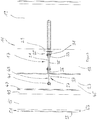
- Weitere Vorteile und Merkmale ergeben sich aus der nachfolgenden Beschreibung eines Ausführungsbeispiels der Erfindung unter Bezugnahme auf die schematischen Darstellungen. Es zeigen in nicht massstabsgetreuer Darstellung:
- Figur 1:
- eine axonometrische Darstellung einer erfindungsgemässen Fassadenkonstruktion;
- Figur 2:
- eine Seitenansicht der Fassadenkonstruktion aus
Figur 1 und - Figur 3:
- eine Draufsicht auf die Fassadenkonstruktion aus
Figur 1 - Die in den
Figuren 1 bis 3 gezeigte Fassadenkonstruktion ist gesamthaft mit dem Bezugszeichen 11 bezeichnet. Die erfindungsgemässe Fassadenkonstruktion 11 hat eine besonders gute Wärmedämmung, da sie erste und zweite Wärmedämmungselemente 13,15 umfasst, welche hintereinander angeordnet sind. Die ersten Wärmedämmungselemente 13 sind von einer Haltevorrichtung 17 direkt an einer Aussenwand 19 eines Gebäudes gehalten. Die Haltevorrichtung 17 umfasst mehrere Distanzhalter 21 und Halteschienen 23. Die Anzahl der Distanzhalter 21 pro m2 Aussenwand 19 richtet sich nach dem Gesamtgewicht der Fassadenkonstruktion 11 und beträgt zwischen 0,4 und 3 Stück und bevorzugt zwischen 0,6 und 2 Stück pro m2. - Der Distanzhalter 21 besitzt ein erstes, der Aussenwand 19 zugewandtes Ende 25 und ein zweites der Aussenwand 19 abgewandtes Ende 27. Das erste Ende 25 besitzt ein Fusselement 29. Das Fusselement 29 ist zweckmässigerweise von länglicher Gestalt und umfasst zwei Durchgangsöffnungen (in den Figuren von Schrauben 31 verdeckt). Mit den Schrauben 31 wird das Fusselement 29 bzw. der gesamte Distanzhalter 21 an der Aussenwand 19 durch eine Schrauben-Dübel-Verbindung befestigt. Der Distanzhalter 21 ist im Wesentlichen vertikal orientiert, um ein möglichst hohes Biegemoment in vertikaler Richtung zu besitzen. Bevorzugt sind die Durchgangsöffnungen als Langlöcher ausgeformt, damit der Distanzhalter 21 an der Aussenwand 19 entlang der Vertikalen ausgerichtet werden kann. An dem Fusselement 29 ist ein erstes U-Profil 33 an- oder ausgeformt. In dem ersten U-Profil 31 ist ein Mittelsteg 35 aufgenommen und mit dem ersten U-Profil 33 verbunden, beispielsweise vernietet. Der Mittelsteg 35 ist auch mit dem zweiten Ende 27 verbunden, beispielsweise vernietet. Auch das zweite Ende 27 ist als ein zweites U-Profil 36 ausgebildet, in welches der Mittelsteg 35 eingesteckt ist.
- Das zweite Ende 27 verjüngt sich zu einem Endsteg 37, an welchem ein Innengewinde 39 zur Aufnahme einer Klemmschraube 41 ausgeformt ist. An dem Endsteg 37 ist auch ein Schlitz 43 vorgesehen, in welchen die Klemmschraube 41 hineinragt, wenn sie zugedreht wird.
- Die Halteschiene 23 umfasst einen Schenkel 45 und einen an den Schenkel 45 bevorzugt rechtwinkelig anschliessenden Montagesteg 47. Der Schenkel 45 lässt sich unterschiedlich tief in den Schlitz 43 einführen und dann mit der Klemmschraube 41 in dem Schlitz 43 verklemmen. Dadurch lässt sich der Abstand zwischen Aussenwand 19 und Montagesteg 47 stufenlos einstellen. Zischen der Aussenwand 19 und dem Montagesteg 47 können daher erste Wärmedämmungselemente 13 mit unterschiedlichen Dicken gehalten sein. Sind alle Haltevorrichtungen 17 einmal an der Aussenwand 19 montiert und der Abstand zwischen der Aussenwand 19 und dem Montagesteg 47 auf die Dicke der zu montierenden ersten Wärmedämmungselemente 13 justiert, lassen sich die ersten Wärmedämmungselemente 13 rasch montieren. Die ersten Wärmedämmungselemente 13 sind zwischen einem oberen und einem unteren benachbarten horizontalen Montagesteg 47 einzuklappen. Dies erfolgt werkzeuglos und ohne zusätzliche Haltemittel.
- Die Montagestege 47 erfüllen eine zweifache Aufgabe. Einerseits werden an ihren Innenseiten die ersten Wärmedämmungsplatten 13 gehalten und andererseits dienen ihre Aussenseiten als Montageflächen für eine Mehrzahl von Montageplatten 49. Die Montageplatten 49 können als Spanplatten ausgeführt sein, also aus Holz hergestellt sein, aber auch aus Kunststoff. Die Montageplatten 49 werden an den Montagestegen 47 angenagelt oder angeschraubt. Werden die Montageplatten 49 bündig, also Stoss an Stoss, auf den Halteschienen verlegt, so entsteht eine plane Montagefläche zur Verlegung der zweiten Wärmedämmungselemente 15 (Wärmedämmplatten).
- Die zweiten Wärmedämmungselemente 15 sind kompakter und haben eine höhere Dichte als die ersten Wärmedämmungselemente 13. Da die zweiten Wärmedämmungselemente 15 relativ fest sind, können diese an die Montagefläche, bestehend aus Montageplatten 49, genagelt (geschossen) oder geschraubt werden. Die Montage der zweiten Wärmedämmungselemente 15 kann auf der planen Montagefläche sehr rasch erfolgen, da die Wärmedämmungselemente 15 an der Unterkonstruktion nicht eingehängt werden müssen, oder auf andere Gegebenheiten der Unterkonstruktion geachtet werden muss.
- Auf die ebene Fläche der montierten zweiten Wärmedämmungselemente 15 kann direkt eine Schutzschicht 51 aufgebracht werden. In bekannter Weise wird dazu zuerst eine Grundputzschicht 53 aufgebracht, in welche aus Festigkeitsgründen ein Netz (Armierungsgewebe) eingelegt ist. Dann wird eine Deckputzschicht 55 auf den Grundputz aufgetragen. Die Putzschicht schützt die Fassadenkonstruktion 11 und insbesondere die zweite Wärmedämmungsschicht 15 vor äusseren Witterungseinflüssen und gibt der Fassadenkonstruktion das gewünschte äussere Erscheinungsbild.
- Das Verfahren zum Aufbau der Fassadenkonstruktion 11 an einem Tragwerk 19 umfasst die folgenden Schritte in chronologischer Abfolge. Die Distanzhalter 21 werden mit ihren ersten Enden 25 (Fusselemente 29) an dem Tragwerk 19 befestigt, insbesondere angeschraubt. Die Distanzhalter 21 können in vertikaler Richtung durch die an den Fusselementen 29 vorgesehenen Langlöcher in vertikaler Richtung justiert werden. Dabei sind die Distanzhalter 21 in horizontalen Reihen anzuordnen. Die vertikalen Abstände der horizontalen Reihen entsprechen im Wesentlichen der Länge der ersten Wärmedämmplatten 13. Der Querschnitt der Mittelstege 35 ist dabei vertikal auszurichten, damit die Mittelstege 35 eine gute Biegesteifigkeit in vertikaler Richtung, also in Richtung der Schwerkraft, aufweisen.
- Die Schlitze 43 der horizontalen Distanzhalterreihen sind in einer horizontalen Linie auszurichten. In die Schlitze 43 wird der Schenkel 45 einer Halteschiene 23 eingesteckt und zwar so tief, dass der Abstand der Montagestege 47 zum Tragwerk 19 im Wesentlichen der Stärke der ersten Wärmedämmplatten 13 entspricht. Die Halteschiene 23 wird dann durch Festziehen der Schrauben 31 in den Schlitzen 43 eingeklemmt.
- Die ersten Wärmedämmplatten 13 können zwischen übereinander liegenden Halteschienen 23 eingehängt werden. Die ersten Wärmedämmplatten 13 werden von den Rückseiten der Montagestege 47 an dem Tragwerk 19 gehalten und benötigen keine weiteren Befestigungsvorkehrungen. Dementsprechend rasch lassen sich die ersten Wärmedämmplatten 13 an dem Tragwerk 19 befestigen.
- An der Aussenseite der Montagestege 47 wird eine Mehrzahl von Montageplatten 49 befestigt, bevorzugt mit einem Nagelschussapparat angenagelt. Die Befestigung der Montageplatten 49 kann ebenfalls rasch vollzogen werden. Die nebeneinander auf Stoss befestigten Montageplatten 49 bilden eine geschlossene Montagefläche.
- Der geschlossenen Montagefläche, gebildet durch die Montageplatten 49, ist es geschuldet, dass die zweiten Wärmedämmplatten 15 rasch an den Montagplatten 49 angenagelt werden können, insbesondere mit einem Nagelschussapparat. Dabei ist nicht darauf zu achten, dass die Nägel einen bestimmten Bereich der Montageplatten 49 treffen müssten, da die Montageplatten 49 an jeder Stelle gleiche Festigkeitseigenschaften aufweisen.
- Die Dichte bzw. Festigkeit der zweiten Wärmedämmplatten 15 ist ausreichend, dass die verwendeten Nägel (auch Klammern oder Schrauben sind denkbar) nicht ausreissen. Falls Klammern zur Anwendung kommen, können die Klammern durch einen Elektrotacker oder einen pneumatischen Tacker durch die zweiten Wärmedämmplatten 15 in die Montageplatten 49 getrieben werden.
- Auf die zweiten Wärmedämmplatten 15 wird beispielsweise eine Grundputzschicht 53 mit Netzarmierung und eine Deckputzschicht 55 aufgebracht.
-
- 11
- Fassadenkonstruktion
- 13
- Erstes Wärmedämmungselement, erste Wärmedämmplatten
- 15
- Zweites Wärmedämmungselement, zweite Wärmedämmplatten
- 17
- Haltevorrichtung
- 19
- Aussenwand, Tragwerk
- 21
- Distanzhalter
- 23
- Halteschiene
- 25
- Erstes Ende des Distanzhalters
- 27
- Zweites Ende des Distanzhalters
- 29
- Fusselement
- 31
- Schrauben
- 33
- Erstes U-Profil
- 35
- Mittelsteg
- 36
- Zweites U-Profil
- 37
- Endsteg
- 39
- Innengewinde
- 41
- Klemmschraube
- 43
- Schlitz
- 45
- Schenkel
- 47
- Montagesteg
- 49
- Montageplatte
- 51
- Schutzzschicht
- 53
- Grundputzschicht, Armierungsschicht
- 55
- Deckputzschicht
Claims (13)
- Fassadenkonstruktion (11) umfassend- erste Wärmedämmplatten (13) mit einer ersten Dichte, welche an einem Tragwerk (19), insbesondere einer Aussenwand eines Gebäudes, angeordnet sind,- zweite Wärmedämmplatten (15) mit einer zweiten Dichte, welche an den ersten Wärmedämmplatten (13) angeordnet sind und deren zweite Dichte grösser als die erste Dichte der ersten Wärmedämmplatten (13) ist,- einer Haltevorrichtung (17), welche an dem Tragwerk (19) angeordnet ist und die ersten und zweiten Wärmedämmplatten (13,15) an dem Tragwerk (19) hält und- einer Schutzschicht (51), welche die zweiten Wärmedämmplatten vor Umwelteinflüssen, wie Nässe oder mechanischer Belastung schützt, weiter gekennzeichnet- durch eine Zwischenlage in Gestalt einer Mehrzahl von Montageplatten (49), welche Zwischenlage an der Haltevorrichtung (17) befestigt und von dieser getragen ist, wobei die Mehrzahl von Montageplatten (49) nebeneinander an der Haltevorrichtung (17) befestigt sind, wodurch sie eine Montagefläche bilden auf welcher die zweiten Wärmedämmplatten (15) verlegt sind und- dadurch, dass die ersten Wärmedämmplatten (13) am Tragwerk (19) und an der Zwischenlage anliegen, wodurch die Fassadenkonstruktion (11) im Wesentlichen frei von einer Hinterlüftung ist.
- Fassadenkonstruktion nach Anspruch 1, dadurch gekennzeichnet, dass die Haltevorrichtung (19) mehrere Distanzhalter (21) mit einem ersten und zweiten Ende (25,27) und eine Halteschiene (23) umfasst, wobei das erste Ende (25) zur Festlegung an dem Tragwerk (19) ausgebildet ist und das zweite Ende (27) zur Befestigung der Halteschiene (23) ausgebildet ist.
- Fassadenkonstruktion nach Anspruch 2, dadurch gekennzeichnet, dass das zweite Ende (27) des Distanzhalters (21) einen Schlitz (43) aufweist, in welchen die Halteschiene (23) einschiebbar ist.
- Fassadenkonstruktion nach Anspruch 3, dadurch gekennzeichnet, dass die Halteschiene (23) durch Form- oder Kraftschluss in dem Schlitz (43) gehalten ist.
- Fassadenkonstruktion nach einem der Ansprüche 3 bis 4, dadurch gekennzeichnet, dass die Halteschiene (23) einen Schenkel (45) zum Einführen in den Schlitz und einen an den Schenkel (45) anschliessenden Steg (47) zur Befestigung der Montageplatte (49) aufweist.
- Fassadenkonstruktion nach einem der Ansprüche 2 bis 5, dadurch gekennzeichnet, dass das erste und zweite Ende (25,27) des Distanzhalters (21) durch einen Mittelsteg (35) verbunden sind, welcher eine reduzierte Wärmeleitfähigkeit zur Vermeidung von Wärmebrücken aufweist.
- Fassadenkonstruktion nach Anspruch 6, dadurch gekennzeichnet, dass die Mittelstegquerschnitte im Wesentlichen vertikal orientiert sind und die Halteschienen (23) im Wesentlichen horizontal in den Distanzhaltern (21) ausgerichtet sind.
- Fassadenkonstruktion nach einem der Ansprüche 1 bis 7, dadurch gekennzeichnet, dass die ersten Wärmedämmplatten (13) eine Dichte haben, deren oberer Wert 90 kg/m3, bevorzugt 70 und besonders bevorzugt 60 kg/m3 beträgt und deren unterer Wert 20 kg/m3, bevorzugt 30 kg/m3 und besonders bevorzugt 35 kg/m3 beträgt.
- Fassadenkonstruktion nach einem der Ansprüche 1 bis 8, dadurch gekennzeichnet, dass die zweiten Wärmedämmplatten (15) eine Dichte haben, deren oberer Wert 150 kg/m3, bevorzugt 130 und besonders bevorzugt 100 kg/m3 beträgt und deren unterer Wert 50 kg/ m3, bevorzugt 60 kg/m3 und besonders bevorzugt 70 kg/m3 beträgt
- Fassadenkonstruktion nach einem der Ansprüche 1 bis 9, dadurch gekennzeichnet, dass auf die freie Oberfläche der zweiten Wärmedämmplatten (15) die Schutzschicht (51) direkt aufbringbar ist, wobei die Schutzschicht (51) eine Armierungsschicht (53) umfasst.
- Fassadenkonstruktion nach einem der Ansprüche 2 bis 9, dadurch gekennzeichnet, dass die Montageplatten (49) mit Nägeln, bevorzugt mit ballistischer Ausbildung, an den Halteschienen (23) befestigt sind.
- Fassadenkonstruktion nach einem der Ansprüche 1 bis 11, dadurch gekennzeichnet, dass die zweiten Wärmedämmplatten (15) mit Nägeln, bevorzugt mit ballistischer Ausbildung, an den Montageplatten (49) befestigt sind.
- Verfahren zum Aufbau einer Fassadenkonstruktion nach Anspruch 1, bei welchem- Distanzhalter (21), welche ein erstes und ein zweites Ende (25,27) aufweisen, mit ihren ersten Enden (25) an einem Tragwerk (19) in horizontalen Reihen befestigt werden, wobei die vertikalen Abstände der horizontalen Reihen im Wesentlichen der Länge von ersten Wärmedämmplatten (13) entsprechen,- in an den zweiten Enden (27) der Distanzhalter vorgesehenen Schlitzen (43) der horizontalen Distanzhalterreihen Halteschienen (23) eingesteckt werden und zwar so tief, dass der Abstand der Halteschienen (23) zum Tragwerk (19) im Wesentlichen der Stärke von ersten Wärmedämmplatten (13) entspricht,- die Halteschienen (23) durch Festziehen von Schrauben (31), welche in die Schlitzen (43) ragen, eingeklemmt werden,- erste Wärmedämmplatten (13) zwischen übereinander liegenden Halteschienen (23) eingehängt werden,- an der Aussenseite der Halteschienen (23) eine Mehrzahl von Montageplatten (49) mit Befestigungsmitteln befestigt werden, bevorzugt mit Nägeln, abgeschossen aus einem Nagelschussapparat, angenagelt werden und- an einer bevorzugt geschlossenen Montagefläche, gebildet durch die Montageplatten (49), zweite Wärmedämmplatten (15) an den Montagplatten (49) mit Nägeln, abgeschossen aus einem Nagelschussapparat, angenagelt werden.
Priority Applications (1)
| Application Number | Priority Date | Filing Date | Title |
|---|---|---|---|
| PL15720578T PL3137703T3 (pl) | 2014-04-30 | 2015-04-29 | Konstrukcja elewacji |
Applications Claiming Priority (2)
| Application Number | Priority Date | Filing Date | Title |
|---|---|---|---|
| CH00646/14A CH709574B1 (de) | 2014-04-30 | 2014-04-30 | Fassadenkonstruktion. |
| PCT/CH2015/000068 WO2015164987A1 (de) | 2014-04-30 | 2015-04-29 | Fassadenkonstruktion |
Publications (2)
| Publication Number | Publication Date |
|---|---|
| EP3137703A1 EP3137703A1 (de) | 2017-03-08 |
| EP3137703B1 true EP3137703B1 (de) | 2018-06-06 |
Family
ID=50729308
Family Applications (1)
| Application Number | Title | Priority Date | Filing Date |
|---|---|---|---|
| EP15720578.2A Active EP3137703B1 (de) | 2014-04-30 | 2015-04-29 | Fassadenkonstruktion |
Country Status (7)
| Country | Link |
|---|---|
| US (1) | US10024054B2 (de) |
| EP (1) | EP3137703B1 (de) |
| CH (1) | CH709574B1 (de) |
| HU (1) | HUE039626T2 (de) |
| PL (1) | PL3137703T3 (de) |
| RU (1) | RU2647523C1 (de) |
| WO (1) | WO2015164987A1 (de) |
Families Citing this family (5)
| Publication number | Priority date | Publication date | Assignee | Title |
|---|---|---|---|---|
| CN110056154A (zh) * | 2019-05-23 | 2019-07-26 | 金螳螂精装科技(苏州)有限公司 | 一种装配式墙板的找平连接结构及安装结构 |
| DE102019128118A1 (de) | 2019-10-17 | 2021-04-22 | Matthias Elsässer | Fassadenelement und Verfahren zur energetischen Sanierung von Gebäuden |
| CN113266084B (zh) * | 2021-04-12 | 2022-08-09 | 朱秦江 | 一种墙面绝缘调平系统及其在节能墙体中的应用方法 |
| US20230323660A1 (en) * | 2022-04-11 | 2023-10-12 | United States Gypsum Company | Building with noncombustible exterior structural wall |
| NO349054B1 (en) * | 2024-05-31 | 2025-09-08 | Glava As | Façade insulating system |
Family Cites Families (9)
| Publication number | Priority date | Publication date | Assignee | Title |
|---|---|---|---|---|
| DE2201621A1 (de) * | 1972-01-14 | 1973-07-19 | Hans Hasenkopf | Fassaden-unterkonstruktion |
| DE7902266U1 (de) * | 1979-01-27 | 1979-06-13 | Haase, Walter, 2071 Klein Hansdorf | Bausatz zur halterung von vertikalen tragprofilen mit gleitpunkten und festpunkten zur befestigung grossflaechiger plattenfoermig ausgebildeter gegenstaende, insbesondere fassadenplatten an gebaeuden |
| DE2849727A1 (de) * | 1978-11-16 | 1980-05-29 | Modersohn Gmbh & Co Kg Wilh | Hoeheneinstellbare klinkerabfangung |
| DE3213899A1 (de) * | 1982-04-15 | 1983-10-27 | Walther Dipl.-Ing. 4952 Porta Westfalica Schröder | Vorrichtung zum aufhaengen von betonfertigteilen |
| CA1199810A (en) * | 1983-11-15 | 1986-01-28 | Ovila Asselin | Heat insulated tie rod for concrete wall members |
| DE3407867A1 (de) * | 1984-03-02 | 1985-09-05 | Paul Ensle Stiftung & Co KG, 7100 Heilbronn | Fertigbau-wandelement |
| RU2289003C2 (ru) * | 2005-02-10 | 2006-12-10 | Азат Хайдарович Гельманов | Кляммер для крепления облицовочных плит |
| CH699778A1 (de) * | 2008-10-21 | 2010-04-30 | Wagner System Ag | Verbindungsteil für Gebäudehüllenverkleidung. |
| CH702578A1 (de) * | 2010-01-18 | 2011-07-29 | Flumroc Ag | Fassadendämmung. |
-
2014
- 2014-04-30 CH CH00646/14A patent/CH709574B1/de unknown
-
2015
- 2015-04-29 RU RU2016146487A patent/RU2647523C1/ru active
- 2015-04-29 EP EP15720578.2A patent/EP3137703B1/de active Active
- 2015-04-29 WO PCT/CH2015/000068 patent/WO2015164987A1/de not_active Ceased
- 2015-04-29 HU HUE15720578A patent/HUE039626T2/hu unknown
- 2015-04-29 PL PL15720578T patent/PL3137703T3/pl unknown
- 2015-04-29 US US15/307,947 patent/US10024054B2/en active Active
Non-Patent Citations (1)
| Title |
|---|
| None * |
Also Published As
| Publication number | Publication date |
|---|---|
| US10024054B2 (en) | 2018-07-17 |
| RU2647523C1 (ru) | 2018-03-16 |
| WO2015164987A1 (de) | 2015-11-05 |
| US20170081849A1 (en) | 2017-03-23 |
| CH709574B1 (de) | 2017-05-31 |
| PL3137703T3 (pl) | 2018-10-31 |
| EP3137703A1 (de) | 2017-03-08 |
| CH709574A1 (de) | 2015-10-30 |
| HUE039626T2 (hu) | 2019-01-28 |
Similar Documents
| Publication | Publication Date | Title |
|---|---|---|
| EP2354368B1 (de) | Befestigungsbügel für Wandisolierungen | |
| EP2526235B1 (de) | Fassadendämmung | |
| DE102017118005A1 (de) | Trockenbau-Trennwandsystem sowie Verfahren zur Montage eines derartigen Trockenbau-Trennwandsystems | |
| DE69832105T2 (de) | Wand einer Gebäudefassade | |
| WO2015164987A1 (de) | Fassadenkonstruktion | |
| DE29920358U1 (de) | Stoßfugenelement für Fassadenplatten | |
| EP2589725B1 (de) | Verbindungselement und System für Lüftungsprofile für hinterlüftete Fassaden von Gebäuden | |
| DE3329789A1 (de) | Waermegedaemmte vorhangfassade | |
| EP2820197B1 (de) | Dämmelement | |
| EP2392749A2 (de) | Halteprofil und Set mit Halteprofil | |
| EP2647779B1 (de) | Haltewinkel für eine Fassadenunterkonstruktion | |
| EP3176357B1 (de) | Aufnahmeelement für eine beschattungseinrichtung und verfahren zum befestigen eines solchen an der aussenseite eines gebäudes | |
| EP4353938A1 (de) | Plattenförmiges tragesystem zur leibungsauskragenden montage von bauelementen | |
| DE1484009A1 (de) | Haus in Fertigbauweise,plattenfoermiges Bauelement zur Herstellung dieses Hauses,Zwischenstueck zur Verbindung der Bauelemente und Verfahren zur Herstellung des Hauses | |
| EP0204015B1 (de) | Bausatz zur Herstellung einer wärmegedämmten Vorhangfassade | |
| DE102008064836B3 (de) | Pfostenleiste zur Anbringung an einem vertikalen Laibungsabschnitt einer Türöffnung sowie Montageeinrichtung zur Befestigung in der Laibung einer Türöffnung | |
| EP1707699A2 (de) | Hinterlüftete wärmegedämmte Gebäudefassade | |
| DE7805757U1 (de) | Bausatz fuer eine trennwand fuer raeume, vornehmlich zur abtrennung von kellerraeumen | |
| DE19804166C2 (de) | Fassadenbekleidung mit Fassadenplatten | |
| DE102018131854B4 (de) | Haltevorrichtung für zumindest ein Dämmelement | |
| DE2648935A1 (de) | Aus wenigstens einer bauplatte bestehende montagewand | |
| DE29805952U1 (de) | Schalldämmende Innen- oder Außenwandbekleidung | |
| DE20000540U1 (de) | Vario-Block für WDVS-Fassaden | |
| AT18565U1 (de) | Hinterlüftete Holzfassade | |
| EP4538478A2 (de) | Vorgehängte fassade |
Legal Events
| Date | Code | Title | Description |
|---|---|---|---|
| STAA | Information on the status of an ep patent application or granted ep patent |
Free format text: STATUS: THE INTERNATIONAL PUBLICATION HAS BEEN MADE |
|
| PUAI | Public reference made under article 153(3) epc to a published international application that has entered the european phase |
Free format text: ORIGINAL CODE: 0009012 |
|
| STAA | Information on the status of an ep patent application or granted ep patent |
Free format text: STATUS: REQUEST FOR EXAMINATION WAS MADE |
|
| 17P | Request for examination filed |
Effective date: 20161116 |
|
| AK | Designated contracting states |
Kind code of ref document: A1 Designated state(s): AL AT BE BG CH CY CZ DE DK EE ES FI FR GB GR HR HU IE IS IT LI LT LU LV MC MK MT NL NO PL PT RO RS SE SI SK SM TR |
|
| AX | Request for extension of the european patent |
Extension state: BA ME |
|
| DAV | Request for validation of the european patent (deleted) | ||
| DAX | Request for extension of the european patent (deleted) | ||
| REG | Reference to a national code |
Ref country code: DE Ref legal event code: R079 Ref document number: 502015004547 Country of ref document: DE Free format text: PREVIOUS MAIN CLASS: E04F0013040000 Ipc: E04B0001780000 |
|
| GRAP | Despatch of communication of intention to grant a patent |
Free format text: ORIGINAL CODE: EPIDOSNIGR1 |
|
| STAA | Information on the status of an ep patent application or granted ep patent |
Free format text: STATUS: GRANT OF PATENT IS INTENDED |
|
| RIC1 | Information provided on ipc code assigned before grant |
Ipc: E04F 13/08 20060101ALI20171128BHEP Ipc: E04B 1/78 20060101AFI20171128BHEP Ipc: E04F 13/04 20060101ALI20171128BHEP Ipc: E04B 2/96 20060101ALI20171128BHEP Ipc: E04B 1/76 20060101ALI20171128BHEP |
|
| INTG | Intention to grant announced |
Effective date: 20171214 |
|
| GRAS | Grant fee paid |
Free format text: ORIGINAL CODE: EPIDOSNIGR3 |
|
| GRAA | (expected) grant |
Free format text: ORIGINAL CODE: 0009210 |
|
| STAA | Information on the status of an ep patent application or granted ep patent |
Free format text: STATUS: THE PATENT HAS BEEN GRANTED |
|
| AK | Designated contracting states |
Kind code of ref document: B1 Designated state(s): AL AT BE BG CH CY CZ DE DK EE ES FI FR GB GR HR HU IE IS IT LI LT LU LV MC MK MT NL NO PL PT RO RS SE SI SK SM TR |
|
| RAP1 | Party data changed (applicant data changed or rights of an application transferred) |
Owner name: ROCKWOOL INTERNATIONAL A/S |
|
| REG | Reference to a national code |
Ref country code: GB Ref legal event code: FG4D Free format text: NOT ENGLISH |
|
| REG | Reference to a national code |
Ref country code: CH Ref legal event code: EP Ref country code: AT Ref legal event code: REF Ref document number: 1006241 Country of ref document: AT Kind code of ref document: T Effective date: 20180615 |
|
| REG | Reference to a national code |
Ref country code: IE Ref legal event code: FG4D Free format text: LANGUAGE OF EP DOCUMENT: GERMAN |
|
| REG | Reference to a national code |
Ref country code: DE Ref legal event code: R096 Ref document number: 502015004547 Country of ref document: DE |
|
| REG | Reference to a national code |
Ref country code: CH Ref legal event code: NV Representative=s name: NOVAGRAAF INTERNATIONAL SA, CH |
|
| REG | Reference to a national code |
Ref country code: NL Ref legal event code: MP Effective date: 20180606 |
|
| REG | Reference to a national code |
Ref country code: LT Ref legal event code: MG4D |
|
| PG25 | Lapsed in a contracting state [announced via postgrant information from national office to epo] |
Ref country code: NO Free format text: LAPSE BECAUSE OF FAILURE TO SUBMIT A TRANSLATION OF THE DESCRIPTION OR TO PAY THE FEE WITHIN THE PRESCRIBED TIME-LIMIT Effective date: 20180906 Ref country code: FI Free format text: LAPSE BECAUSE OF FAILURE TO SUBMIT A TRANSLATION OF THE DESCRIPTION OR TO PAY THE FEE WITHIN THE PRESCRIBED TIME-LIMIT Effective date: 20180606 Ref country code: LT Free format text: LAPSE BECAUSE OF FAILURE TO SUBMIT A TRANSLATION OF THE DESCRIPTION OR TO PAY THE FEE WITHIN THE PRESCRIBED TIME-LIMIT Effective date: 20180606 Ref country code: ES Free format text: LAPSE BECAUSE OF FAILURE TO SUBMIT A TRANSLATION OF THE DESCRIPTION OR TO PAY THE FEE WITHIN THE PRESCRIBED TIME-LIMIT Effective date: 20180606 Ref country code: SE Free format text: LAPSE BECAUSE OF FAILURE TO SUBMIT A TRANSLATION OF THE DESCRIPTION OR TO PAY THE FEE WITHIN THE PRESCRIBED TIME-LIMIT Effective date: 20180606 Ref country code: CY Free format text: LAPSE BECAUSE OF FAILURE TO SUBMIT A TRANSLATION OF THE DESCRIPTION OR TO PAY THE FEE WITHIN THE PRESCRIBED TIME-LIMIT Effective date: 20180606 Ref country code: BG Free format text: LAPSE BECAUSE OF FAILURE TO SUBMIT A TRANSLATION OF THE DESCRIPTION OR TO PAY THE FEE WITHIN THE PRESCRIBED TIME-LIMIT Effective date: 20180906 |
|
| REG | Reference to a national code |
Ref country code: SK Ref legal event code: T3 Ref document number: E 27975 Country of ref document: SK |
|
| PG25 | Lapsed in a contracting state [announced via postgrant information from national office to epo] |
Ref country code: LV Free format text: LAPSE BECAUSE OF FAILURE TO SUBMIT A TRANSLATION OF THE DESCRIPTION OR TO PAY THE FEE WITHIN THE PRESCRIBED TIME-LIMIT Effective date: 20180606 Ref country code: RS Free format text: LAPSE BECAUSE OF FAILURE TO SUBMIT A TRANSLATION OF THE DESCRIPTION OR TO PAY THE FEE WITHIN THE PRESCRIBED TIME-LIMIT Effective date: 20180606 Ref country code: GR Free format text: LAPSE BECAUSE OF FAILURE TO SUBMIT A TRANSLATION OF THE DESCRIPTION OR TO PAY THE FEE WITHIN THE PRESCRIBED TIME-LIMIT Effective date: 20180907 Ref country code: HR Free format text: LAPSE BECAUSE OF FAILURE TO SUBMIT A TRANSLATION OF THE DESCRIPTION OR TO PAY THE FEE WITHIN THE PRESCRIBED TIME-LIMIT Effective date: 20180606 |
|
| PG25 | Lapsed in a contracting state [announced via postgrant information from national office to epo] |
Ref country code: NL Free format text: LAPSE BECAUSE OF FAILURE TO SUBMIT A TRANSLATION OF THE DESCRIPTION OR TO PAY THE FEE WITHIN THE PRESCRIBED TIME-LIMIT Effective date: 20180606 |
|
| REG | Reference to a national code |
Ref country code: HU Ref legal event code: AG4A Ref document number: E039626 Country of ref document: HU |
|
| PG25 | Lapsed in a contracting state [announced via postgrant information from national office to epo] |
Ref country code: IS Free format text: LAPSE BECAUSE OF FAILURE TO SUBMIT A TRANSLATION OF THE DESCRIPTION OR TO PAY THE FEE WITHIN THE PRESCRIBED TIME-LIMIT Effective date: 20181006 Ref country code: EE Free format text: LAPSE BECAUSE OF FAILURE TO SUBMIT A TRANSLATION OF THE DESCRIPTION OR TO PAY THE FEE WITHIN THE PRESCRIBED TIME-LIMIT Effective date: 20180606 Ref country code: RO Free format text: LAPSE BECAUSE OF FAILURE TO SUBMIT A TRANSLATION OF THE DESCRIPTION OR TO PAY THE FEE WITHIN THE PRESCRIBED TIME-LIMIT Effective date: 20180606 |
|
| PG25 | Lapsed in a contracting state [announced via postgrant information from national office to epo] |
Ref country code: SM Free format text: LAPSE BECAUSE OF FAILURE TO SUBMIT A TRANSLATION OF THE DESCRIPTION OR TO PAY THE FEE WITHIN THE PRESCRIBED TIME-LIMIT Effective date: 20180606 |
|
| REG | Reference to a national code |
Ref country code: DE Ref legal event code: R097 Ref document number: 502015004547 Country of ref document: DE |
|
| PLBE | No opposition filed within time limit |
Free format text: ORIGINAL CODE: 0009261 |
|
| STAA | Information on the status of an ep patent application or granted ep patent |
Free format text: STATUS: NO OPPOSITION FILED WITHIN TIME LIMIT |
|
| 26N | No opposition filed |
Effective date: 20190307 |
|
| PG25 | Lapsed in a contracting state [announced via postgrant information from national office to epo] |
Ref country code: DK Free format text: LAPSE BECAUSE OF FAILURE TO SUBMIT A TRANSLATION OF THE DESCRIPTION OR TO PAY THE FEE WITHIN THE PRESCRIBED TIME-LIMIT Effective date: 20180606 Ref country code: SI Free format text: LAPSE BECAUSE OF FAILURE TO SUBMIT A TRANSLATION OF THE DESCRIPTION OR TO PAY THE FEE WITHIN THE PRESCRIBED TIME-LIMIT Effective date: 20180606 |
|
| PG25 | Lapsed in a contracting state [announced via postgrant information from national office to epo] |
Ref country code: AL Free format text: LAPSE BECAUSE OF FAILURE TO SUBMIT A TRANSLATION OF THE DESCRIPTION OR TO PAY THE FEE WITHIN THE PRESCRIBED TIME-LIMIT Effective date: 20180606 |
|
| REG | Reference to a national code |
Ref country code: BE Ref legal event code: MM Effective date: 20190430 |
|
| PG25 | Lapsed in a contracting state [announced via postgrant information from national office to epo] |
Ref country code: LU Free format text: LAPSE BECAUSE OF NON-PAYMENT OF DUE FEES Effective date: 20190429 Ref country code: MC Free format text: LAPSE BECAUSE OF FAILURE TO SUBMIT A TRANSLATION OF THE DESCRIPTION OR TO PAY THE FEE WITHIN THE PRESCRIBED TIME-LIMIT Effective date: 20180606 |
|
| PG25 | Lapsed in a contracting state [announced via postgrant information from national office to epo] |
Ref country code: BE Free format text: LAPSE BECAUSE OF NON-PAYMENT OF DUE FEES Effective date: 20190430 |
|
| PG25 | Lapsed in a contracting state [announced via postgrant information from national office to epo] |
Ref country code: TR Free format text: LAPSE BECAUSE OF FAILURE TO SUBMIT A TRANSLATION OF THE DESCRIPTION OR TO PAY THE FEE WITHIN THE PRESCRIBED TIME-LIMIT Effective date: 20180606 |
|
| PG25 | Lapsed in a contracting state [announced via postgrant information from national office to epo] |
Ref country code: IE Free format text: LAPSE BECAUSE OF NON-PAYMENT OF DUE FEES Effective date: 20190429 |
|
| PG25 | Lapsed in a contracting state [announced via postgrant information from national office to epo] |
Ref country code: PT Free format text: LAPSE BECAUSE OF FAILURE TO SUBMIT A TRANSLATION OF THE DESCRIPTION OR TO PAY THE FEE WITHIN THE PRESCRIBED TIME-LIMIT Effective date: 20181008 |
|
| PG25 | Lapsed in a contracting state [announced via postgrant information from national office to epo] |
Ref country code: MT Free format text: LAPSE BECAUSE OF FAILURE TO SUBMIT A TRANSLATION OF THE DESCRIPTION OR TO PAY THE FEE WITHIN THE PRESCRIBED TIME-LIMIT Effective date: 20180606 |
|
| PG25 | Lapsed in a contracting state [announced via postgrant information from national office to epo] |
Ref country code: MK Free format text: LAPSE BECAUSE OF FAILURE TO SUBMIT A TRANSLATION OF THE DESCRIPTION OR TO PAY THE FEE WITHIN THE PRESCRIBED TIME-LIMIT Effective date: 20180606 |
|
| REG | Reference to a national code |
Ref country code: DE Ref legal event code: R081 Ref document number: 502015004547 Country of ref document: DE Owner name: ROCKWOOL A/S, DK Free format text: FORMER OWNER: ROCKWOOL INTERNATIONAL A/S, HEDEHUSENE, DK Ref country code: DE Ref legal event code: R082 Ref document number: 502015004547 Country of ref document: DE |
|
| REG | Reference to a national code |
Ref country code: HU Ref legal event code: HC9C Owner name: ROCKWOOL A/S, DK Free format text: FORMER OWNER(S): ROCKWOOL INTERNATIONAL A/S, DK |
|
| REG | Reference to a national code |
Ref country code: SK Ref legal event code: TC4A Ref document number: E 27975 Country of ref document: SK Owner name: ROCKWOOL A/S, HEDEHUSENE, DK Effective date: 20230823 |
|
| REG | Reference to a national code |
Ref country code: AT Ref legal event code: HC Ref document number: 1006241 Country of ref document: AT Kind code of ref document: T Owner name: ROCKWOOL A/S, DK Effective date: 20230929 |
|
| PGFP | Annual fee paid to national office [announced via postgrant information from national office to epo] |
Ref country code: PL Payment date: 20250403 Year of fee payment: 11 Ref country code: DE Payment date: 20250429 Year of fee payment: 11 |
|
| PGFP | Annual fee paid to national office [announced via postgrant information from national office to epo] |
Ref country code: GB Payment date: 20250428 Year of fee payment: 11 |
|
| PGFP | Annual fee paid to national office [announced via postgrant information from national office to epo] |
Ref country code: HU Payment date: 20250422 Year of fee payment: 11 |
|
| PGFP | Annual fee paid to national office [announced via postgrant information from national office to epo] |
Ref country code: IT Payment date: 20250422 Year of fee payment: 11 |
|
| PGFP | Annual fee paid to national office [announced via postgrant information from national office to epo] |
Ref country code: FR Payment date: 20250425 Year of fee payment: 11 |
|
| PGFP | Annual fee paid to national office [announced via postgrant information from national office to epo] |
Ref country code: CH Payment date: 20250501 Year of fee payment: 11 |
|
| PGFP | Annual fee paid to national office [announced via postgrant information from national office to epo] |
Ref country code: AT Payment date: 20250402 Year of fee payment: 11 |
|
| PGFP | Annual fee paid to national office [announced via postgrant information from national office to epo] |
Ref country code: CZ Payment date: 20250408 Year of fee payment: 11 |
|
| PGFP | Annual fee paid to national office [announced via postgrant information from national office to epo] |
Ref country code: SK Payment date: 20260331 Year of fee payment: 12 |
|
| REG | Reference to a national code |
Ref country code: CH Ref legal event code: U11 Free format text: ST27 STATUS EVENT CODE: U-0-0-U10-U11 (AS PROVIDED BY THE NATIONAL OFFICE) Effective date: 20260501 |