EP3136557B1 - Elektrische rotationsmaschine - Google Patents
Elektrische rotationsmaschine Download PDFInfo
- Publication number
- EP3136557B1 EP3136557B1 EP14893469.8A EP14893469A EP3136557B1 EP 3136557 B1 EP3136557 B1 EP 3136557B1 EP 14893469 A EP14893469 A EP 14893469A EP 3136557 B1 EP3136557 B1 EP 3136557B1
- Authority
- EP
- European Patent Office
- Prior art keywords
- cooling oil
- coils
- electric machine
- rotary electric
- machine according
- Prior art date
- Legal status (The legal status is an assumption and is not a legal conclusion. Google has not performed a legal analysis and makes no representation as to the accuracy of the status listed.)
- Active
Links
Images


Classifications
-
- H—ELECTRICITY
- H02—GENERATION; CONVERSION OR DISTRIBUTION OF ELECTRIC POWER
- H02K—DYNAMO-ELECTRIC MACHINES
- H02K9/00—Arrangements for cooling or ventilating
- H02K9/19—Arrangements for cooling or ventilating for machines with closed casing and closed-circuit cooling using a liquid cooling medium, e.g. oil
-
- H—ELECTRICITY
- H02—GENERATION; CONVERSION OR DISTRIBUTION OF ELECTRIC POWER
- H02K—DYNAMO-ELECTRIC MACHINES
- H02K1/00—Details of the magnetic circuit
- H02K1/06—Details of the magnetic circuit characterised by the shape, form or construction
- H02K1/12—Stationary parts of the magnetic circuit
-
- H—ELECTRICITY
- H02—GENERATION; CONVERSION OR DISTRIBUTION OF ELECTRIC POWER
- H02K—DYNAMO-ELECTRIC MACHINES
- H02K3/00—Details of windings
- H02K3/04—Windings characterised by the conductor shape, form or construction, e.g. with bar conductors
- H02K3/24—Windings characterised by the conductor shape, form or construction, e.g. with bar conductors with channels or ducts for cooling medium between the conductors
-
- H—ELECTRICITY
- H02—GENERATION; CONVERSION OR DISTRIBUTION OF ELECTRIC POWER
- H02K—DYNAMO-ELECTRIC MACHINES
- H02K5/00—Casings; Enclosures; Supports
- H02K5/04—Casings or enclosures characterised by the shape, form or construction thereof
- H02K5/20—Casings or enclosures characterised by the shape, form or construction thereof with channels or ducts for flow of cooling medium
- H02K5/203—Casings or enclosures characterised by the shape, form or construction thereof with channels or ducts for flow of cooling medium specially adapted for liquids, e.g. cooling jackets
Definitions
- the present invention relates to a rotary electric machine such as an electric motor or a generator that is mounted to a hybrid automobile or an electric automobile, for example, and particularly relates to an oil cooling construction for a stator coil.
- first and second coil ends are formed circumferentially at two axial end portions of a stator core, first and second cooling oil spraying portions are disposed on an upper portion of each of the first and second coil ends, and cooling oil is sprayed from the first and second cooling oil spraying portions and is supplied to the upper portion of each of the first and second coil ends.
- stator core segments are disposed annularly in a circumferential direction, coils are wound onto each of the stator core segments so as to be arranged annularly, circumferential oil channels are formed on an inner side surface of a housing so as to face the coils that are arranged annularly, openings of the circumferential oil channels are covered by annular oil channel covers, a plurality of nozzles are formed on the oil channel covers so as to face between the stator core segments or between the coils, cooling oil that is supplied to the circumferential oil channels is sprayed from the nozzles, and is supplied to the coils from axial directions.
- the present invention aims to solve the above problems and an object of the present invention is to provide a rotary electric machine that reduces pressure loss and minimizes pumping power by making a surface of a cooling oil channel that faces a coil into an opening, and that also suppresses temperature increases in the coil and enables reductions in size to be achieved by changing cooling oil that flows through the cooling oil channel into an axial flow so as to be supplied between the coils using oil flow direction changing projections.
- a rotary electric machine includes: an externally mounted frame; a rotor that is rotatably disposed inside the externally mounted frame such that an axial direction of a shaft is horizontal; a stator including: an annular stator core that is disposed coaxially so as to surround the rotor and that is held by the externally mounted frame; and a plurality of coils that are mounted to the stator core so as to be arranged in an annular shape; an annular cooling oil channel that is configured inside the externally mounted frame so as to face axially toward the plurality of coils that are arranged in the annular shape and such that a surface that faces the plurality of coils is made into an opening; an oil pump; a nozzle that sprays cooling oil that is conveyed under pressure from the oil pump into the cooling oil channel from above; and the invention is characterized by a plurality of oil flow direction changing projections that are respectively disposed inside the cooling oil channel and are arranged circumferentially so as to face gaps between coils among the plurality of
- the surface of the cooling oil channel that faces the coils is made into an opening, pressure loss in the cooling oil channel is reduced, enabling the required pumping power to be reduced.
- a compact oil pump can thereby be used, enabling the rotary electric machine to be reduced in size.
- the cooling oil is supplied approximately uniformly to the plurality of coils that are arranged in an annular shape. Because the coil temperature is thereby made uniform, and the thermal rating of the rotary electric machine is improved, the rotary electric machine can be reduced in size. In addition, because the cooling oil is supplied intensively to gaps between the coils, which become hottest, the coils can be cooled effectively.
- Figure 1 is a cross section that shows a rotary electric machine according to Embodiment 1 of the present invention
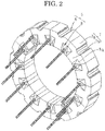
- Figure 2 is an oblique projection that shows a stator in the rotary electric machine according to Embodiment 1 of the present invention
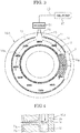
- Figure 3 is a front elevation that shows a first externally mounted frame in the rotary electric machine according to Embodiment 1 of the present invention
- Figure 4 is a schematic cross section that explains cooling oil flow in stator coils of the rotary electric machine according to Embodiment 1 of the present invention.
- arrows in Figures 1 through 4 represent cooling oil flow.
- a rotary electric machine 100 that includes: a rotor 1 that is rotatably disposed inside first and second externally mounted frames 10A and 10B; a stator 5 that is held by the first and second externally mounted frames 10A and 10B so as to surround the rotor 1 so as to have a constant air gap interposed between the stator 5 and the rotor 1; and a cooling mechanism 20 that cools the stator 5.
- the rotor 1 includes: a shaft 2; a rotor core 3 that is fixed to the shaft 2; and permanent magnets 4 that are mounted to the rotor core 3 to constitute magnetic poles, the rotor 1 being rotatably disposed inside the stator 5.
- the stator 5 includes: an annular stator core 6; and a stator coil 8 that is mounted to the stator core 6.
- Core segments 7 include: a circular arc-shaped back yoke portion 7a; and a tooth 7b that protrudes radially inward from a circumferentially central portion of an inner circumferential surface of the back yoke portion 7a.
- the stator core 6 is configured by arranging twelve core segments 7 into an annular shape such that circumferential side surfaces of the back yoke portions 7a are butted against each other.
- the stator coil 8 is constituted by twelve coils 8a that are each produced by winding a conductor wire for a plurality of turns onto the teeth 7b of the core segments 7.
- the twelve coils 8a constitute a U-phase coil, a V-phase coil, a W-phase coil, a U-phase coil, a V-phase coil, a W-phase coil, etc., in order circumferentially, for example, such that the stator coil 8 forms a three-phase alternating-current winding.
- the first externally mounted frame 10A is produced so as to have a cup shape that covers a first axial end of the stator 5.
- a radially outer peripheral wall portion 11 and an inner circumferential peripheral wall portion 12 are respectively formed concentrically on an inside wall surface of the first externally mounted frame 10A so as to protrude in an axial direction in annular shapes, to constitute an annular cooling oil channel 29.
- a vertically upper portion position of the radially outer peripheral wall portion 11 is cut away to constitute an oil inflow aperture 13.
- Twelve oil flow direction changing projections 14 are respectively formed on a circumference of a common circle on an inside wall surface of the first externally mounted frame 10A so as to protrude in an axial direction such that cooling oil receiving surfaces 14a are oriented upward.
- the cooling oil receiving surfaces 14a are formed so as to have flat surfaces that are perpendicular to a vertical direction.
- the twelve oil flow direction changing projections 14 are respectively formed inside the cooling oil channel 29 so as to face gaps between the circumferentially adjacent coils 8a in an axial direction. Amounts of axial protrusion of the radially outer peripheral wall portion 11, the inner circumferential peripheral wall portion 12, and the oil flow direction changing projections 14 are equal.
- the second externally mounted frame 10B is produced so as to have a cup shape that covers a second axial end of the stator 5.
- a cooling oil channel is not formed on an inside wall surface of the second externally mounted frame 10B.
- the cooling mechanism 20 includes: a nozzle 21 that is positioned vertically above the oil inflow aperture 13, and that sprays cooling oil 19 so as to be supplied into the cooling oil channel 29 through the oil inflow aperture 13; and an oil pump 22 that draws cooling oil 19 that has accumulated in lower portion spaces inside the first and second externally mounted frames 10A and 10B, and conveys it under pressure to the nozzle 21.
- cooling oil 19 is conveyed under pressure to the nozzle 21 by the oil pump 22 and is sprayed from the nozzle 21.
- the cooling oil 19 that is sprayed from the nozzle 21 is supplied to the cooling oil channel 29 from the oil inflow aperture 13, flows downward through the cooling oil channel 29, as indicated by arrows in Figure 3 .
- the cooling oil 19 that has flowed downward through the cooling oil channel 29 is changed into axial flow by contacting the cooling oil receiving surfaces 14a of the oil flow direction changing projections 14.
- the cooling oil 19 that has been changed to an axial flow is discharged from the cooling oil channel 29, specifically so as to be directed at the gaps between circumferentially adjacent coils 8a from a first axial end.
- portions of the cooling oil 19 flow through the gaps between the coils 8a to a second axial end.
- the cooling oil that has flowed out at the second axial end of the coils 8a flows downward along the coils 8a.
- a remaining portion of the cooling oil 19 contacts surfaces of the coils 8a, and flows downward along the coils 8a.
- an annular cooling oil channel 29 that is formed on an inside wall surface of a first externally mounted frame 10A is an open flow channel that has an opening on a side that faces the stator coil 8.
- pressure loss in the cooling oil channel 29 is reduced, reducing the load on the oil pump 22.
- the cooling oil 19 flows through the cooling oil channel 29 due to deadweight and pressure that results from deadweight, the load that acts on the oil pump 22 is reduced.
- Mechanical power of the oil pump 22 can thereby be reduced, making reductions in the size of the oil pump 22 possible, and enabling downsizing of the rotary electric machine 100 to be achieved.
- cooling oil 19 flows through the gaps between the adjacent coils 8a from the first axial end to the second axial end. Contact area between the cooling oil 19 and the coils 8a is increased thereby, enabling the gaps between the coils 8a, which become hottest, to be cooled effectively.
- the oil flow direction changing projections 14 are disposed inside the cooling oil channel 29 so as to face the gaps between the circumferentially adjacent coils 8a, the coils 8a that constitute the stator coil 8 are cooled uniformly. Temperatures are thereby prevented from rising in portions of the coils 8a and making the thermal rating of the rotary electric machine 100 impossible to improve, enabling downsizing of the rotary electric machine 100 to be achieved.
- the coils 8a are concentrated winding coils, the coil ends are reduced, enabling the rotary electric machine 100 to be reduced in size.
- copper loss is reduced in the concentrated winding coils 8a, reducing the amount of heat generated.
- temperature increases in the coils 8a can be reliably suppressed.
- the oil flow direction changing projections are formed such that cooling oil receiving surfaces that are constituted by flat surfaces are horizontal, but oil flow direction changing projections may be formed into inclined surfaces in which cooling oil receiving surfaces that are constituted by flat surfaces become gradually lower toward the coils. In that case, because cooling oil is supplied between the coils such that flow velocity thereof is hastened by colliding with the cooling oil receiving surfaces, the coils can be cooled more efficiently.
- oil flow direction changing projections are disposed such that the cooling oil receiving surfaces thereof, which are constituted by flat surfaces, face gaps between circumferentially adjacent coils, but in consideration of the influence of gravitational force, it is desirable for oil flow direction changing projections to be disposed such that cooling oil receiving surfaces that are constituted by flat surfaces are positioned slightly vertically above the gaps between the circumferentially adjacent coils, rather than level therewith.
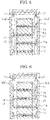
- Figure 5 is a schematic cross section that explains cooling oil flow in stator coils of a rotary electric machine according to Embodiment 2 of the present invention.
- a radially outer peripheral wall portion (not shown) and an inner circumferential peripheral wall portion 12 are respectively formed concentrically on an inside wall surface of first and second externally mounted frames 10A' and 10B' so as to protrude in an axial direction in annular shapes, to constitute an annular cooling oil channel 29.
- a vertically upper portion position of the radially outer peripheral wall portion is cut away to constitute an oil inflow aperture.
- Six oil flow direction changing projections 14 are respectively formed on circumferences of each of two common circles on inside wall surfaces of the first and second externally mounted frames 10A' and 10B' so as to protrude in axial directions such that cooling oil receiving surfaces 14a are oriented upward.
- the oil flow direction changing projections 14 are formed on the inner circumferential wall surfaces of the first and second externally mounted frames 10A' and 10B' such that circumferential positions thereof alternate with each other.
- the oil flow direction changing projections 14 are thereby disposed so as to face gaps between circumferentially adjacent coils 8a so as to alternate between first and second axial ends.
- Embodiment 2 is configured in a similar or identical manner to Embodiment 1 except that the first and second externally mounted frames 10A' and 10B' are used instead of the first and second externally mounted frames 10A and 10B.
- the cooling oil flows through the gaps between the coils 8a from the first axial end to the second axial end.
- cooling oil 19 that is supplied into the cooling oil channel 29 of the second externally mounted frame 10B' from the nozzle 21 flows downward through the cooling oil channel 29, is changed to axial flow at each of the oil flow direction changing projections 14, and the cooling oil 19 is sprayed into the gaps between the coils 8a from the second axial end.
- the cooling oil 19 flows through the gaps between the coils 8a from the second axial end to the first axial end.
- Embodiment 2 Consequently, similar or identical effects to those of Embodiment 1 can also be achieved in Embodiment 2.
- the temperature of the cooling oil 19 increases gradually from the first axial end toward the second axial end.
- the temperature of the cooling oil 19 increases gradually from the second axial end toward the first axial end.
- oil flow direction changing projections 14 are formed on the inner circumferential wall surfaces of the first and second the externally mounted frame 10A' and 10B' so as to face the gaps between the circumferentially adjacent coils 8a so as to alternate between the first and second axial ends. Consequently, because the cooling oil that flows in adjacent gaps between the coils 8a flows in opposite directions, the temperature distribution in the axial direction of the coils 8a is made uniform, enabling the coils 8a to be cooled effectively.
- Figure 6 is a schematic cross section that explains cooling oil flow in stator coils of a rotary electric machine according to Embodiment 3 of the present invention.
- a radially outer peripheral wall portion (not shown) and an inner circumferential peripheral wall portion 12 are respectively formed concentrically on an inside wall surface of a second externally mounted frame 10B" so as to protrude in an axial direction in annular shapes, to constitute an annular cooling oil channel 29.
- a vertically upper portion position of the radially outer peripheral wall portion is cut away to constitute an oil inflow aperture.
- Twelve oil flow direction changing projections 14 are respectively formed on circumferences of a common circle on an inside wall surface of the second externally mounted frame 10B" so as to protrude in an axial direction such that cooling oil receiving surfaces 14a are oriented upward.
- the oil flow direction changing projections 14 are formed on the inner circumferential wall surfaces of the second externally mounted frame 10B" so as to face gaps between circumferentially adjacent coils 8a.
- Embodiment 3 is configured in a similar or identical manner to Embodiment 1 except that the second externally mounted frame 10B" is used instead of the second externally mounted frame 10B.
- the cooling oil 19 flows through the gaps between the coils 8a from the first axial end toward the second axial end.
- cooling oil 19 that is supplied into the cooling oil channel 29 of the second externally mounted frame 10B" from the nozzle 21 flows downward through the cooling oil channel 29, is changed to axial flow at each of the oil flow direction changing projections 14, and the cooling oil 19 is sprayed into the gaps between the coils 8a from the second axial end.
- the cooling oil 19 flows through the gaps between the coils 8a from the second axial end toward the first axial end, and merges with the cooling oil that has flowed from the first axial end toward the second axial end at axially central portions of the gaps between the coils 8a.
- the temperature distribution in the axial direction of the coils 8a is also made uniform, enabling the coils 8a to be cooled effectively.
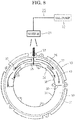
- Figure 7 is a front elevation that shows a first externally mounted frame in a rotary electric machine according to Embodiment 4 of the present invention.
- twelve oil flow direction changing projections 14' are respectively formed on a circumference of a common circle on an inside wall surface of the first externally mounted frame 10A" so as to protrude in an axial direction so as to have a circular arc shape that is convex vertically downward as a cross-sectional shape that is perpendicular to an axial direction.
- cooling oil receiving surfaces 14a' are formed so as to have concave surfaces that are convex downstream in the direction of flow of the cooling oil 19.
- Embodiment 4 is configured in a similar or identical manner to Embodiment 1 except that the first externally mounted frame 10A" is used instead of the first externally mounted frame 10A.
- the cooling oil receiving surfaces 14a' of the oil flow direction changing projections 14' are downwardly convex concave surfaces.
- Figure 8 is a cross section that shows a coil end cover in a rotary electric machine according to Embodiment 5 of the present invention when viewed from an axially inner side. Moreover, Figure 8 is a cross section in which the coil end cover is sectioned in a plane that is perpendicular to an axial direction and is viewed from a first axial end, and arrows in Figure 8 represent cooling oil flow.
- a coil end cover 30 is fixed to an axially inner surface of a first externally mounted frame by screws, for example, and is disposed so as to cover protruding portions (coil ends) of coils 8a that protrude outward at a first axial end of a stator core 6.
- the coil end cover 30 is produced so as to have an annular shape that has a U-shaped cross section in which first axial ends of a radially outer peripheral wall portion 31 and a radially inner peripheral wall portion 32 are linked by a floor portion (not shown) to constitute an annular cooling oil channel 39.
- a cooling oil receiving port 33 that is disposed on a vertically upper portion of the radially outer peripheral wall portion 31 is configured such that cooling oil 19 is supplied to the cooling oil channel 39.
- a first externally mounted cover is produced so as to have a cup shape that covers a first axial end of a stator 5, and radially outer and radially inner peripheral wall portions that form cooling oil channels are not formed.
- a first oil flow direction changing projection 35 is formed so as to protrude axially outward from a vertically upper portion of the bottom portion of the coil end cover 30 in a vicinity of the radially inner peripheral wall portion 32 such that an upper surface (a cooling oil receiving surface) is a flat surface that is perpendicular to the vertical direction.
- Second oil flow direction changing projections 36 are formed so as to protrude axially outward from the floor portion so as to be spaced apart radially outward and circumferentially from the first oil flow direction changing projection 35 so as to have circular arc shapes that are centered around a central axis of the coil end cover 30 as cross-sectional shapes that are perpendicular to an axial direction.
- Third oil flow direction changing projections 37 are formed so as to protrude radially outward from downstream end portions of the second oil flow direction changing projections 36 in a direction of flow of the cooling oil 19.
- a plurality of fourth oil flow direction changing projections 38 are respectively formed in a circumferential direction so as to protrude radially outward from the radially inner peripheral wall portion 32.
- upstream surfaces of the third and fourth oil flow direction changing projections 37 and 38 in the direction of flow of the cooling oil 19 constitute cooling oil receiving surfaces.
- the first oil flow direction changing projection 35 changes the cooling oil 19 that flows in through the cooling oil receiving port 33 into an axial flow and circumferential flows.
- the second oil flow direction changing projections 36 change the cooling oil 19 that flows in through the cooling oil receiving port 33 into circumferential flows.
- the third and fourth oil flow direction changing projections 37 and 38 change the cooling oil 19 that flows through the cooling oil channel 39 in a circumferential direction into axial flows.
- the first, third, and fourth oil flow direction changing projections 35, 37, and 38 are disposed at first axial ends of gaps between each of the circumferentially adjacent coils 8a.
- the cooling oil 19 that is sprayed from the nozzle 21 is supplied into the cooling oil channel 39 of the coil end cover 30 through the cooling oil receiving port 33.
- the cooling oil 19 that has been supplied into the cooling oil channel 39 first contacts the cooling oil receiving surface of the first oil flow direction changing projection 35, a portion thereof is changed to an axial flow, and is supplied to a gap between the coils 8a, and a remaining portion flows circumferentially.
- the cooling oil 19 that has been supplied into the cooling oil channel 39 is also made to flow circumferentially by the second oil flow direction changing projections 36.
- the cooling oil 19 that has flowed circumferentially through the cooling oil channel 29 is changed to axial flows by contacting the cooling oil receiving surfaces of the third and fourth oil flow direction changing projections 37 and 38, and is supplied to the corresponding gaps between the coils 8a.
- Embodiment 5 Similar or identical effects to those of Embodiment 1 can also be achieved in Embodiment 5.
- the first, third, and fourth oil flow direction changing projections 35, 37 and 38 are disposed only in a region in the upper half of the cooling oil channel 39, but it has been confirmed that not only the region in the upper half of the coil group that is arranged in an annular shape, but also the region in the lower half of the coil group, can be cooled effectively thereby.
- the regions in the lower half of the coil group are cooled effectively because portions of the cooling oil 19 that have been supplied to the coils by the first, third, and fourth oil flow direction changing projections 35, 37 and 38 pass downward over the surfaces of the coils, and are supplied to the region in the lower half of the coil group, and also because cooling oil 19 accumulates in lower portion spaces inside the first and second externally mounted frames.
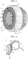
- Figure 9 is an oblique projection that shows a stator in a rotary electric machine according to Embodiment 6 of the present invention
- Figure 10 is an oblique projection that shows a coil that constitutes part of a stator coil in the rotary electric machine according to Embodiment 6 of the present invention
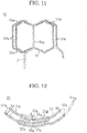
- Figure 11 is a front elevation that shows the coil that constitutes part of the stator coil in the rotary electric machine according to Embodiment 6 of the present invention
- Figure 12 is an end elevation that shows the coil that constitutes part of the stator coil in the rotary electric machine according to Embodiment 6 of the present invention.
- a stator 40 includes: an annular stator core 41; and a stator coil 43 that is mounted to the stator core 41.
- Core segments 42 of the stator core 41 include: a circular arc-shaped back yoke portion 42a; and a tooth 42b that protrudes radially inward from a circumferentially central portion of an inner circumferential surface of the back yoke portion 42a.
- the stator core 41 is configured by arranging the core segments 42 into an annular shape such that circumferential side surfaces of the back yoke portions 42a are butted against each other.
- the stator coil 43 is configured by disposing coils 50 circumferentially around the stator core 41 at a pitch of one slot.
- the coils 50 are distributed windings that are produced by winding conductor wires 51 into edgewise windings, the conductor wires 51 being made of jointless continuous rectangular copper wire that is insulated using an enamel resin, for example.
- the coils 50 are configured such that two ⁇ -shaped coil patterns that are constituted by a first rectilinear portion 50a, a first coil end portion 50e, a second rectilinear portion 50b, a second coil end portion 50f, a third rectilinear portion 50c, a third coil end portion 50g, and a fourth rectilinear portion 50d are arranged in a longitudinal direction of short sides of oblong cross sections of the conductor wires 51, and the fourth rectilinear portion 50d and the first rectilinear portion 50a are linked using a linking wire 52.
- the linking wires 52 constitute coil end portions, and winding start end portions and winding finish end portions of the conductor wires 51 constitute coil terminals 50i.
- a layer of first coil end portions 50e in which the first coil end portions 50e are arranged circumferentially at a pitch of one slot and a layer of third coil end portions 50g in which the third coil end portions 50g are arranged circumferentially at a pitch of one slot are arranged alternately in four layers in a radial direction.
- Embodiment 6 is configured in a similar or identical manner to that of Embodiment 1 above except that the stator 40 is used instead of the stator 5.
- Embodiment 6 in a similar or identical manner to Embodiment 1, the cooling oil 19 that is sprayed from the nozzle 21 is supplied to the cooling oil channel 29 from the oil inflow aperture 13, and is changed into axial flow by contacting the cooling oil receiving surfaces 14a of the oil flow direction changing projections 14. As indicated by the arrows in Figure 9 , the cooling oil 19 that has been changed into an axial flow is discharged so as to be supplied between the first coil end portions 50e and the third coil end portions 50g of the circumferentially adjacent coils 50 from a first axial end, and flows from the first axial end of the coils 50 to a second axial end.
- Embodiment 6 Similar or identical effects to those of Embodiment 1 can also be achieved in Embodiment 6.
- Embodiment 6 because distributed winding coils 50 are used, torque characteristics can be improved compared to the concentrated winding coils 8a in Embodiment 1, but the coil ends are increased in size, copper loss is greater, and the amount of heat generated is increased.
- the present cooling construction because the cooling oil 19 flows between the coils 50, enabling temperature increases in the coils 50 to be suppressed, a rotary electric machine that has superior torque characteristics can be achieved.
- distributed winding coils are used that are produced by winding a conductor wire into a ⁇ -shaped coil pattern, but the distributed winding coils are not limited thereto, and may be hexagonal coils that are produced by winding a conductor wire into a helical shape, for example.
- oil flow direction changing projections are produced into flat plate shapes or plate shapes that have circular arc-shaped cross sections, but the oil flow direction changing projections are not limited to these shapes, provided that the direction of the cooling oil flow can be changed axially, and may be produced into plate shapes that have V-shaped cross sections or wave-shaped cross sections, for example.
- oil flow direction changing projections are disposed so as to face all of the gaps between the coils, but it is not absolutely necessary for the oil flow direction changing projections to be disposed so as to face all of the gaps between the coils, provided that they are distributed approximately uniformly in a circumferential direction, and they may be disposed so as to face every second gap between the coils in a circumferential direction, for example.
Landscapes
- Engineering & Computer Science (AREA)
- Power Engineering (AREA)
- Motor Or Generator Cooling System (AREA)
- Motor Or Generator Frames (AREA)
Claims (10)
- Elektrische Rotationsmaschine, aufweisend:einen extern angebrachten Rahmen (10A, 10A', 10A", 10B, 10B', 10B");einen Rotor (1), der im Inneren des extern angebrachten Rahmens (10A, 10A', 10A", 10B, 10B', 10B") derart rotierend angeordnet ist, dass eine Axialrichtung einer Welle (2) horizontal ist;einen Stator (5), aufweisend:einen ringförmigen Statorkern (6), der koaxial angeordnet ist, so dass er den Rotor (1) umgibt, und der durch den extern angebrachten Rahmen (10A, 10A', 10A", 10B, 10B', 10B") gehalten wird; undeine Vielzahl von Spulen (8a, 50), die an dem Statorkern (6) angebracht sind, so dass sie ringförmig angeordnet sind;einen ringförmigen Kühlölkanal (29), der im Inneren des extern angebrachten Rahmens (10A, 10A', 10A", 10B, 10B', 10B") konfiguriert ist, so dass er zu der Vielzahl von ringförmig angeordneten Spulen (8a, 50) axial zugewandt ist, und derart angeordnet ist, dass eine Oberfläche, die der Vielzahl von Spulen (88a, 50) zugewandt ist, in einer Öffnung ausgebildet ist;eine Ölpumpe (22);eine Düse (21), die Kühlöl (19), das von der Ölpumpe (22) in den Kühlölkanal (29) unter Druck transportiert wird, von oben sprüht;gekennzeichnet durcheine Vielzahl von Ölströmungsrichtungsänderungsvorsprüngen (14, 14', 35, 36, 37, 38), die jeweils im Inneren des Kühlölkanals (29) angeordnet und umlaufend angeordnet sind, so dass sie Abständen zwischen Spulen unter der Vielzahl von Spulen (8a, 50) zugewandt sind, und derart, dass Kühlölempfangsoberflächen (14a, 14a') in einer Strömungsrichtung des Kühlöls (19) stromaufwärts zugewandt sind, so dass sie das Kühlöl, das durch den Kühlölkanal (29) strömt, zu einer Axialströmung ändern, um den Abständen zwischen den Spulen (8a, 50) zugeführt zu werden.
- Elektrische Rotationsmaschine nach Anspruch 1, wobei die Kühlölempfangsoberfläche (14a') von jedem der Vielzahl von Ölströmungsrichtungsänderungsvorsprüngen (14') in einer konkaven Oberfläche ausgebildet ist, die in der Strömungsrichtung des Kühlöls (19) stromabwärts konvex ist.
- Elektrische Rotationsmaschine nach Anspruch 1 oder Anspruch 2, wobei der Kühlölkanal (29) nur an einem ersten axialen Ende des Stators (5) angeordnet ist.
- Elektrische Rotationsmaschine nach Anspruch 1 oder Anspruch 2, wobei der Kühlölkanal (29) an zwei axialen Enden des Stators (5) angeordnet ist.
- Elektrische Rotationsmaschine nach Anspruch 4, wobei die Vielzahl von Ölströmungsrichtungsänderungsvorsprüngen (14) in jedem der an den zwei axialen Enden des Stators (5) angeordneten Kühlölkanäle (29) derart angeordnet sind, dass umlaufende Positionen derselben ausgerichtet sind, so dass sie das Kühlöl (19) identischen Abständen zwischen den Spulen (8a, 50) von zwei axialen Enden zuführen.
- Elektrische Rotationsmaschine nach Anspruch 4, wobei die Vielzahl von Ölströmungsrichtungsänderungsvorsprüngen (14) in jedem der an den zwei axialen Enden des Stators (5) angeordneten Kühlölkanäle (29) derart angeordnet sind, dass umlaufende Positionen derselben alternieren, so dass sie das Kühlöl (19) alternierenden Abständen zwischen den Spulen (8a, 50) zuführen.
- Elektrische Rotationsmaschine nach einem der Ansprüche 1 bis 6, wobei der Kühlölkanal (29) an einer inneren Wandfläche des extern angebrachten Rahmens (10A, 10A', 10A", 10B, 10B', 10B") ausgebildet ist.
- Elektrische Rotationsmaschine nach einem der Ansprüche 1 bis 6, ferner mit einer Spulenendabdeckung (30), die an dem extern angebrachten Rahmen angebracht ist, und die angeordnet ist, so dass sie die Vielzahl von ringförmig angeordneten Spulen (8a, 50) abdecken,
wobei die Spulenendabdeckung (30) den Kühlölkanal (29) ausbildet. - Elektrische Rotationsmaschine nach einem der Ansprüche 1 bis 8, wobei die Vielzahl von Spulen konzentrierte Wicklungsspulen (8a) sind.
- Elektrische Rotationsmaschine nach einem der Ansprüche 1 bis 8, wobei die Vielzahl von Spulen verteilte Wicklungsspulen (50) sind.
Applications Claiming Priority (1)
| Application Number | Priority Date | Filing Date | Title |
|---|---|---|---|
| PCT/JP2014/063975 WO2015181889A1 (ja) | 2014-05-27 | 2014-05-27 | 回転電機 |
Publications (3)
| Publication Number | Publication Date |
|---|---|
| EP3136557A1 EP3136557A1 (de) | 2017-03-01 |
| EP3136557A4 EP3136557A4 (de) | 2017-12-13 |
| EP3136557B1 true EP3136557B1 (de) | 2019-09-18 |
Family
ID=54698273
Family Applications (1)
| Application Number | Title | Priority Date | Filing Date |
|---|---|---|---|
| EP14893469.8A Active EP3136557B1 (de) | 2014-05-27 | 2014-05-27 | Elektrische rotationsmaschine |
Country Status (5)
| Country | Link |
|---|---|
| US (1) | US10404139B2 (de) |
| EP (1) | EP3136557B1 (de) |
| JP (1) | JP6526647B2 (de) |
| CN (1) | CN106464086B (de) |
| WO (1) | WO2015181889A1 (de) |
Families Citing this family (16)
| Publication number | Priority date | Publication date | Assignee | Title |
|---|---|---|---|---|
| JP6436200B1 (ja) | 2017-08-25 | 2018-12-12 | 株式会社明電舎 | 回転電機の固定子の冷却構造 |
| KR102452689B1 (ko) | 2017-09-26 | 2022-10-11 | 현대자동차주식회사 | 오일 코일순환방식 모터 및 친환경차량 |
| JP6877315B2 (ja) * | 2017-11-08 | 2021-05-26 | タイガースポリマー株式会社 | 回転電機の冷却構造 |
| JP6942881B2 (ja) * | 2018-03-30 | 2021-09-29 | 本田技研工業株式会社 | 回転電機の冷却構造 |
| EP3886299B1 (de) * | 2018-11-20 | 2024-06-26 | JATCO Ltd | Motorölkühlstruktur |
| EP4535619A3 (de) * | 2019-01-14 | 2025-07-23 | Shanghai Pangood Power Technology Co., Ltd. | Kühlsystem, statoranordnung und axialmagnetfeldmotor |
| EP3709484A1 (de) * | 2019-03-14 | 2020-09-16 | Siemens Aktiengesellschaft | Gekapselte elektrische maschine mit äusserem flüssigkeitskühlkreislauf |
| CN111193351B (zh) * | 2020-03-16 | 2025-01-24 | 南京清研易为新能源动力有限责任公司 | 电机机壳 |
| JP6958655B2 (ja) * | 2020-03-19 | 2021-11-02 | 株式会社明電舎 | 回転機 |
| CN112615445B (zh) * | 2020-11-25 | 2022-05-13 | 华为数字能源技术有限公司 | 电机、动力总成和设备 |
| CN117716615A (zh) * | 2021-07-26 | 2024-03-15 | 株式会社爱信 | 驱动装置 |
| CN115189520B (zh) * | 2022-07-25 | 2024-06-25 | 重庆长安汽车股份有限公司 | 一种电驱油冷电机及汽车 |
| JP7790292B2 (ja) * | 2022-07-26 | 2025-12-23 | トヨタ自動車株式会社 | 回転電機の冷却構造 |
| JP7468591B1 (ja) | 2022-09-29 | 2024-04-16 | 株式会社明電舎 | 回転電機の冷却構造および回転電機 |
| CN118282080B (zh) * | 2024-06-03 | 2024-09-27 | 苏州英磁新能源科技有限公司 | 一种轴向磁通盘式电机冷却系统及油道结构 |
| CN118554700B (zh) * | 2024-06-04 | 2025-10-28 | 广东汇天航空航天科技有限公司 | 冷却结构、电机和交通设备 |
Family Cites Families (17)
| Publication number | Priority date | Publication date | Assignee | Title |
|---|---|---|---|---|
| JP3385373B2 (ja) | 1994-10-31 | 2003-03-10 | アイシン・エィ・ダブリュ株式会社 | モ−タの冷却回路 |
| FR2736769B1 (fr) * | 1995-07-13 | 1997-10-10 | Jeumont Ind | Procede de reparation d'une boite a fluide de refroidissement d'une barre statorique d'un alternateur electrique |
| US5798587A (en) * | 1997-01-22 | 1998-08-25 | Industrial Technology Research Institute | Cooling loop structure of high speed spindle |
| JP3707250B2 (ja) * | 1997-08-06 | 2005-10-19 | 富士電機システムズ株式会社 | 回転電気機械の円筒形回転子 |
| JP3661529B2 (ja) * | 1999-11-17 | 2005-06-15 | 日産自動車株式会社 | モータの冷却装置 |
| JP3864728B2 (ja) * | 2001-06-20 | 2007-01-10 | 日産自動車株式会社 | 回転電機 |
| JP4167886B2 (ja) * | 2002-11-25 | 2008-10-22 | 株式会社日本自動車部品総合研究所 | 回転電機 |
| JP2004238952A (ja) | 2003-02-06 | 2004-08-26 | Yasuo Suina | 入り隅用役物雨樋 |
| JP2006033924A (ja) | 2004-07-13 | 2006-02-02 | Toshiba Corp | 車両用通風冷却形主電動機 |
| JP5347380B2 (ja) | 2008-08-28 | 2013-11-20 | アイシン精機株式会社 | モータの油冷構造 |
| US8487489B2 (en) * | 2010-07-30 | 2013-07-16 | General Electric Company | Apparatus for cooling an electric machine |
| JP2012170299A (ja) | 2011-02-16 | 2012-09-06 | Toyota Motor Corp | モータの冷却装置 |
| JP2013207930A (ja) | 2012-03-28 | 2013-10-07 | Honda Motor Co Ltd | 回転電機のステータ構造 |
| JP5920108B2 (ja) * | 2012-08-23 | 2016-05-18 | トヨタ自動車株式会社 | 回転電機装置 |
| US20160141921A1 (en) * | 2014-11-17 | 2016-05-19 | Arnold Magnetic Technologies | Helical heat exchanger for electric motors |
| US20160164378A1 (en) * | 2014-12-04 | 2016-06-09 | Atieva, Inc. | Motor Cooling System |
| JP6560033B2 (ja) * | 2015-06-25 | 2019-08-14 | 株式会社日立製作所 | 回転電機、並びに回転電機の冷却システム |
-
2014
- 2014-05-27 WO PCT/JP2014/063975 patent/WO2015181889A1/ja not_active Ceased
- 2014-05-27 US US15/304,592 patent/US10404139B2/en active Active
- 2014-05-27 CN CN201480078943.4A patent/CN106464086B/zh active Active
- 2014-05-27 EP EP14893469.8A patent/EP3136557B1/de active Active
- 2014-05-27 JP JP2016523009A patent/JP6526647B2/ja active Active
Non-Patent Citations (1)
| Title |
|---|
| None * |
Also Published As
| Publication number | Publication date |
|---|---|
| EP3136557A1 (de) | 2017-03-01 |
| JPWO2015181889A1 (ja) | 2017-04-20 |
| JP6526647B2 (ja) | 2019-06-05 |
| US20170047822A1 (en) | 2017-02-16 |
| US10404139B2 (en) | 2019-09-03 |
| CN106464086B (zh) | 2019-11-15 |
| EP3136557A4 (de) | 2017-12-13 |
| CN106464086A (zh) | 2017-02-22 |
| WO2015181889A1 (ja) | 2015-12-03 |
Similar Documents
| Publication | Publication Date | Title |
|---|---|---|
| EP3136557B1 (de) | Elektrische rotationsmaschine | |
| US10103602B2 (en) | Rotary electric machine | |
| EP2461463B1 (de) | Elektrische rotationsmaschine | |
| US10320247B2 (en) | Embedded permanent magnet rotary electric machine | |
| RU2649972C2 (ru) | Охлаждающий зазор полюсного башмака для аксиального двигателя | |
| US9742242B2 (en) | Rotary electric machine including a stator coil end cooling construction and rotor with dual fan blades | |
| JP6079012B2 (ja) | 3相回転電機 | |
| US9906103B2 (en) | Rotary electrical machine cooling apparatus | |
| CN108574352B (zh) | 旋转电机 | |
| WO2013157101A1 (ja) | ステータ、モータ、送風機及びステータの製造方法 | |
| KR20170011145A (ko) | 로터 조립체 및 이를 포함하는 모터 | |
| US20130062978A1 (en) | Electric rotating machine | |
| JP2014107874A (ja) | 回転電機 | |
| JP5955437B1 (ja) | 回転電機 | |
| JP2015006030A (ja) | 回転電機 | |
| JP2015208138A (ja) | 車両用回転電機 | |
| JP2015012792A (ja) | 回転電機のステータ | |
| EP3039776B1 (de) | Elektrische maschine mit einem statorgehäuse mit erhöhter kühlungseffizienz | |
| CN104283347A (zh) | 旋转电机 | |
| JP5330860B2 (ja) | 回転電機 | |
| US9362794B2 (en) | Stator winding comprising multiple phase windings | |
| JP5363221B2 (ja) | ステータ | |
| CN103580313B (zh) | 电机的定子和具有其的电机、压缩机 | |
| JP6801444B2 (ja) | ステータ | |
| CN117616667A (zh) | 电机 |
Legal Events
| Date | Code | Title | Description |
|---|---|---|---|
| STAA | Information on the status of an ep patent application or granted ep patent |
Free format text: STATUS: THE INTERNATIONAL PUBLICATION HAS BEEN MADE |
|
| PUAI | Public reference made under article 153(3) epc to a published international application that has entered the european phase |
Free format text: ORIGINAL CODE: 0009012 |
|
| STAA | Information on the status of an ep patent application or granted ep patent |
Free format text: STATUS: REQUEST FOR EXAMINATION WAS MADE |
|
| 17P | Request for examination filed |
Effective date: 20161124 |
|
| AK | Designated contracting states |
Kind code of ref document: A1 Designated state(s): AL AT BE BG CH CY CZ DE DK EE ES FI FR GB GR HR HU IE IS IT LI LT LU LV MC MK MT NL NO PL PT RO RS SE SI SK SM TR |
|
| AX | Request for extension of the european patent |
Extension state: BA ME |
|
| DAX | Request for extension of the european patent (deleted) | ||
| A4 | Supplementary search report drawn up and despatched |
Effective date: 20171114 |
|
| RIC1 | Information provided on ipc code assigned before grant |
Ipc: H02K 9/19 20060101AFI20171108BHEP Ipc: H02K 5/20 20060101ALI20171108BHEP Ipc: H02K 3/24 20060101ALI20171108BHEP |
|
| GRAP | Despatch of communication of intention to grant a patent |
Free format text: ORIGINAL CODE: EPIDOSNIGR1 |
|
| STAA | Information on the status of an ep patent application or granted ep patent |
Free format text: STATUS: GRANT OF PATENT IS INTENDED |
|
| RIC1 | Information provided on ipc code assigned before grant |
Ipc: H02K 5/20 20060101ALI20190314BHEP Ipc: H02K 9/19 20060101AFI20190314BHEP Ipc: H02K 3/24 20060101ALI20190314BHEP |
|
| INTG | Intention to grant announced |
Effective date: 20190411 |
|
| GRAS | Grant fee paid |
Free format text: ORIGINAL CODE: EPIDOSNIGR3 |
|
| GRAA | (expected) grant |
Free format text: ORIGINAL CODE: 0009210 |
|
| STAA | Information on the status of an ep patent application or granted ep patent |
Free format text: STATUS: THE PATENT HAS BEEN GRANTED |
|
| AK | Designated contracting states |
Kind code of ref document: B1 Designated state(s): AL AT BE BG CH CY CZ DE DK EE ES FI FR GB GR HR HU IE IS IT LI LT LU LV MC MK MT NL NO PL PT RO RS SE SI SK SM TR |
|
| REG | Reference to a national code |
Ref country code: GB Ref legal event code: FG4D |
|
| REG | Reference to a national code |
Ref country code: CH Ref legal event code: EP |
|
| REG | Reference to a national code |
Ref country code: DE Ref legal event code: R096 Ref document number: 602014054072 Country of ref document: DE |
|
| REG | Reference to a national code |
Ref country code: AT Ref legal event code: REF Ref document number: 1182478 Country of ref document: AT Kind code of ref document: T Effective date: 20191015 |
|
| REG | Reference to a national code |
Ref country code: IE Ref legal event code: FG4D |
|
| REG | Reference to a national code |
Ref country code: NL Ref legal event code: MP Effective date: 20190918 |
|
| PG25 | Lapsed in a contracting state [announced via postgrant information from national office to epo] |
Ref country code: HR Free format text: LAPSE BECAUSE OF FAILURE TO SUBMIT A TRANSLATION OF THE DESCRIPTION OR TO PAY THE FEE WITHIN THE PRESCRIBED TIME-LIMIT Effective date: 20190918 Ref country code: BG Free format text: LAPSE BECAUSE OF FAILURE TO SUBMIT A TRANSLATION OF THE DESCRIPTION OR TO PAY THE FEE WITHIN THE PRESCRIBED TIME-LIMIT Effective date: 20191218 Ref country code: SE Free format text: LAPSE BECAUSE OF FAILURE TO SUBMIT A TRANSLATION OF THE DESCRIPTION OR TO PAY THE FEE WITHIN THE PRESCRIBED TIME-LIMIT Effective date: 20190918 Ref country code: LT Free format text: LAPSE BECAUSE OF FAILURE TO SUBMIT A TRANSLATION OF THE DESCRIPTION OR TO PAY THE FEE WITHIN THE PRESCRIBED TIME-LIMIT Effective date: 20190918 Ref country code: FI Free format text: LAPSE BECAUSE OF FAILURE TO SUBMIT A TRANSLATION OF THE DESCRIPTION OR TO PAY THE FEE WITHIN THE PRESCRIBED TIME-LIMIT Effective date: 20190918 Ref country code: NO Free format text: LAPSE BECAUSE OF FAILURE TO SUBMIT A TRANSLATION OF THE DESCRIPTION OR TO PAY THE FEE WITHIN THE PRESCRIBED TIME-LIMIT Effective date: 20191218 |
|
| REG | Reference to a national code |
Ref country code: LT Ref legal event code: MG4D |
|
| PG25 | Lapsed in a contracting state [announced via postgrant information from national office to epo] |
Ref country code: LV Free format text: LAPSE BECAUSE OF FAILURE TO SUBMIT A TRANSLATION OF THE DESCRIPTION OR TO PAY THE FEE WITHIN THE PRESCRIBED TIME-LIMIT Effective date: 20190918 Ref country code: AL Free format text: LAPSE BECAUSE OF FAILURE TO SUBMIT A TRANSLATION OF THE DESCRIPTION OR TO PAY THE FEE WITHIN THE PRESCRIBED TIME-LIMIT Effective date: 20190918 Ref country code: GR Free format text: LAPSE BECAUSE OF FAILURE TO SUBMIT A TRANSLATION OF THE DESCRIPTION OR TO PAY THE FEE WITHIN THE PRESCRIBED TIME-LIMIT Effective date: 20191219 Ref country code: RS Free format text: LAPSE BECAUSE OF FAILURE TO SUBMIT A TRANSLATION OF THE DESCRIPTION OR TO PAY THE FEE WITHIN THE PRESCRIBED TIME-LIMIT Effective date: 20190918 |
|
| REG | Reference to a national code |
Ref country code: AT Ref legal event code: MK05 Ref document number: 1182478 Country of ref document: AT Kind code of ref document: T Effective date: 20190918 |
|
| PG25 | Lapsed in a contracting state [announced via postgrant information from national office to epo] |
Ref country code: AT Free format text: LAPSE BECAUSE OF FAILURE TO SUBMIT A TRANSLATION OF THE DESCRIPTION OR TO PAY THE FEE WITHIN THE PRESCRIBED TIME-LIMIT Effective date: 20190918 Ref country code: PL Free format text: LAPSE BECAUSE OF FAILURE TO SUBMIT A TRANSLATION OF THE DESCRIPTION OR TO PAY THE FEE WITHIN THE PRESCRIBED TIME-LIMIT Effective date: 20190918 Ref country code: EE Free format text: LAPSE BECAUSE OF FAILURE TO SUBMIT A TRANSLATION OF THE DESCRIPTION OR TO PAY THE FEE WITHIN THE PRESCRIBED TIME-LIMIT Effective date: 20190918 Ref country code: ES Free format text: LAPSE BECAUSE OF FAILURE TO SUBMIT A TRANSLATION OF THE DESCRIPTION OR TO PAY THE FEE WITHIN THE PRESCRIBED TIME-LIMIT Effective date: 20190918 Ref country code: RO Free format text: LAPSE BECAUSE OF FAILURE TO SUBMIT A TRANSLATION OF THE DESCRIPTION OR TO PAY THE FEE WITHIN THE PRESCRIBED TIME-LIMIT Effective date: 20190918 Ref country code: NL Free format text: LAPSE BECAUSE OF FAILURE TO SUBMIT A TRANSLATION OF THE DESCRIPTION OR TO PAY THE FEE WITHIN THE PRESCRIBED TIME-LIMIT Effective date: 20190918 Ref country code: IT Free format text: LAPSE BECAUSE OF FAILURE TO SUBMIT A TRANSLATION OF THE DESCRIPTION OR TO PAY THE FEE WITHIN THE PRESCRIBED TIME-LIMIT Effective date: 20190918 Ref country code: PT Free format text: LAPSE BECAUSE OF FAILURE TO SUBMIT A TRANSLATION OF THE DESCRIPTION OR TO PAY THE FEE WITHIN THE PRESCRIBED TIME-LIMIT Effective date: 20200120 |
|
| PG25 | Lapsed in a contracting state [announced via postgrant information from national office to epo] |
Ref country code: SM Free format text: LAPSE BECAUSE OF FAILURE TO SUBMIT A TRANSLATION OF THE DESCRIPTION OR TO PAY THE FEE WITHIN THE PRESCRIBED TIME-LIMIT Effective date: 20190918 Ref country code: IS Free format text: LAPSE BECAUSE OF FAILURE TO SUBMIT A TRANSLATION OF THE DESCRIPTION OR TO PAY THE FEE WITHIN THE PRESCRIBED TIME-LIMIT Effective date: 20200224 Ref country code: CZ Free format text: LAPSE BECAUSE OF FAILURE TO SUBMIT A TRANSLATION OF THE DESCRIPTION OR TO PAY THE FEE WITHIN THE PRESCRIBED TIME-LIMIT Effective date: 20190918 Ref country code: SK Free format text: LAPSE BECAUSE OF FAILURE TO SUBMIT A TRANSLATION OF THE DESCRIPTION OR TO PAY THE FEE WITHIN THE PRESCRIBED TIME-LIMIT Effective date: 20190918 |
|
| REG | Reference to a national code |
Ref country code: DE Ref legal event code: R097 Ref document number: 602014054072 Country of ref document: DE |
|
| PLBE | No opposition filed within time limit |
Free format text: ORIGINAL CODE: 0009261 |
|
| STAA | Information on the status of an ep patent application or granted ep patent |
Free format text: STATUS: NO OPPOSITION FILED WITHIN TIME LIMIT |
|
| PG2D | Information on lapse in contracting state deleted |
Ref country code: IS |
|
| PG25 | Lapsed in a contracting state [announced via postgrant information from national office to epo] |
Ref country code: DK Free format text: LAPSE BECAUSE OF FAILURE TO SUBMIT A TRANSLATION OF THE DESCRIPTION OR TO PAY THE FEE WITHIN THE PRESCRIBED TIME-LIMIT Effective date: 20190918 Ref country code: IS Free format text: LAPSE BECAUSE OF FAILURE TO SUBMIT A TRANSLATION OF THE DESCRIPTION OR TO PAY THE FEE WITHIN THE PRESCRIBED TIME-LIMIT Effective date: 20200119 |
|
| 26N | No opposition filed |
Effective date: 20200619 |
|
| PG25 | Lapsed in a contracting state [announced via postgrant information from national office to epo] |
Ref country code: SI Free format text: LAPSE BECAUSE OF FAILURE TO SUBMIT A TRANSLATION OF THE DESCRIPTION OR TO PAY THE FEE WITHIN THE PRESCRIBED TIME-LIMIT Effective date: 20190918 |
|
| REG | Reference to a national code |
Ref country code: DE Ref legal event code: R119 Ref document number: 602014054072 Country of ref document: DE |
|
| PG25 | Lapsed in a contracting state [announced via postgrant information from national office to epo] |
Ref country code: CH Free format text: LAPSE BECAUSE OF NON-PAYMENT OF DUE FEES Effective date: 20200531 Ref country code: LI Free format text: LAPSE BECAUSE OF NON-PAYMENT OF DUE FEES Effective date: 20200531 Ref country code: MC Free format text: LAPSE BECAUSE OF FAILURE TO SUBMIT A TRANSLATION OF THE DESCRIPTION OR TO PAY THE FEE WITHIN THE PRESCRIBED TIME-LIMIT Effective date: 20190918 |
|
| REG | Reference to a national code |
Ref country code: BE Ref legal event code: MM Effective date: 20200531 |
|
| GBPC | Gb: european patent ceased through non-payment of renewal fee |
Effective date: 20200527 |
|
| PG25 | Lapsed in a contracting state [announced via postgrant information from national office to epo] |
Ref country code: LU Free format text: LAPSE BECAUSE OF NON-PAYMENT OF DUE FEES Effective date: 20200527 |
|
| PG25 | Lapsed in a contracting state [announced via postgrant information from national office to epo] |
Ref country code: GB Free format text: LAPSE BECAUSE OF NON-PAYMENT OF DUE FEES Effective date: 20200527 Ref country code: IE Free format text: LAPSE BECAUSE OF NON-PAYMENT OF DUE FEES Effective date: 20200527 |
|
| PG25 | Lapsed in a contracting state [announced via postgrant information from national office to epo] |
Ref country code: DE Free format text: LAPSE BECAUSE OF NON-PAYMENT OF DUE FEES Effective date: 20201201 Ref country code: BE Free format text: LAPSE BECAUSE OF NON-PAYMENT OF DUE FEES Effective date: 20200531 |
|
| PG25 | Lapsed in a contracting state [announced via postgrant information from national office to epo] |
Ref country code: TR Free format text: LAPSE BECAUSE OF FAILURE TO SUBMIT A TRANSLATION OF THE DESCRIPTION OR TO PAY THE FEE WITHIN THE PRESCRIBED TIME-LIMIT Effective date: 20190918 Ref country code: MT Free format text: LAPSE BECAUSE OF FAILURE TO SUBMIT A TRANSLATION OF THE DESCRIPTION OR TO PAY THE FEE WITHIN THE PRESCRIBED TIME-LIMIT Effective date: 20190918 Ref country code: CY Free format text: LAPSE BECAUSE OF FAILURE TO SUBMIT A TRANSLATION OF THE DESCRIPTION OR TO PAY THE FEE WITHIN THE PRESCRIBED TIME-LIMIT Effective date: 20190918 |
|
| PG25 | Lapsed in a contracting state [announced via postgrant information from national office to epo] |
Ref country code: MK Free format text: LAPSE BECAUSE OF FAILURE TO SUBMIT A TRANSLATION OF THE DESCRIPTION OR TO PAY THE FEE WITHIN THE PRESCRIBED TIME-LIMIT Effective date: 20190918 |
|
| REG | Reference to a national code |
Ref country code: FR Ref legal event code: PLFP Year of fee payment: 10 |
|
| P01 | Opt-out of the competence of the unified patent court (upc) registered |
Effective date: 20230512 |
|
| PGFP | Annual fee paid to national office [announced via postgrant information from national office to epo] |
Ref country code: FR Payment date: 20230411 Year of fee payment: 10 |
|
| PG25 | Lapsed in a contracting state [announced via postgrant information from national office to epo] |
Ref country code: FR Free format text: LAPSE BECAUSE OF NON-PAYMENT OF DUE FEES Effective date: 20240531 |