EP3136341B1 - Surroundings monitoring system for working machine - Google Patents
Surroundings monitoring system for working machine Download PDFInfo
- Publication number
- EP3136341B1 EP3136341B1 EP15782523.3A EP15782523A EP3136341B1 EP 3136341 B1 EP3136341 B1 EP 3136341B1 EP 15782523 A EP15782523 A EP 15782523A EP 3136341 B1 EP3136341 B1 EP 3136341B1
- Authority
- EP
- European Patent Office
- Prior art keywords
- shadow
- image
- working machine
- region
- profile
- Prior art date
- Legal status (The legal status is an assumption and is not a legal conclusion. Google has not performed a legal analysis and makes no representation as to the accuracy of the status listed.)
- Active
Links
Images


Classifications
-
- H—ELECTRICITY
- H04—ELECTRIC COMMUNICATION TECHNIQUE
- H04N—PICTORIAL COMMUNICATION, e.g. TELEVISION
- H04N7/00—Television systems
- H04N7/18—Closed-circuit television [CCTV] systems, i.e. systems in which the video signal is not broadcast
- H04N7/181—Closed-circuit television [CCTV] systems, i.e. systems in which the video signal is not broadcast for receiving images from a plurality of remote sources
-
- B—PERFORMING OPERATIONS; TRANSPORTING
- B60—VEHICLES IN GENERAL
- B60R—VEHICLES, VEHICLE FITTINGS, OR VEHICLE PARTS, NOT OTHERWISE PROVIDED FOR
- B60R1/00—Optical viewing arrangements; Real-time viewing arrangements for drivers or passengers using optical image capturing systems, e.g. cameras or video systems specially adapted for use in or on vehicles
- B60R1/002—Optical viewing arrangements; Real-time viewing arrangements for drivers or passengers using optical image capturing systems, e.g. cameras or video systems specially adapted for use in or on vehicles specially adapted for covering the peripheral part of the vehicle, e.g. for viewing tyres, bumpers or the like
-
- B—PERFORMING OPERATIONS; TRANSPORTING
- B60—VEHICLES IN GENERAL
- B60R—VEHICLES, VEHICLE FITTINGS, OR VEHICLE PARTS, NOT OTHERWISE PROVIDED FOR
- B60R1/00—Optical viewing arrangements; Real-time viewing arrangements for drivers or passengers using optical image capturing systems, e.g. cameras or video systems specially adapted for use in or on vehicles
- B60R1/20—Real-time viewing arrangements for drivers or passengers using optical image capturing systems, e.g. cameras or video systems specially adapted for use in or on vehicles
- B60R1/22—Real-time viewing arrangements for drivers or passengers using optical image capturing systems, e.g. cameras or video systems specially adapted for use in or on vehicles for viewing an area outside the vehicle, e.g. the exterior of the vehicle
- B60R1/23—Real-time viewing arrangements for drivers or passengers using optical image capturing systems, e.g. cameras or video systems specially adapted for use in or on vehicles for viewing an area outside the vehicle, e.g. the exterior of the vehicle with a predetermined field of view
- B60R1/27—Real-time viewing arrangements for drivers or passengers using optical image capturing systems, e.g. cameras or video systems specially adapted for use in or on vehicles for viewing an area outside the vehicle, e.g. the exterior of the vehicle with a predetermined field of view providing all-round vision, e.g. using omnidirectional cameras
-
- B—PERFORMING OPERATIONS; TRANSPORTING
- B60—VEHICLES IN GENERAL
- B60R—VEHICLES, VEHICLE FITTINGS, OR VEHICLE PARTS, NOT OTHERWISE PROVIDED FOR
- B60R11/00—Arrangements for holding or mounting articles, not otherwise provided for
- B60R11/04—Mounting of cameras operative during drive; Arrangement of controls thereof relative to the vehicle
-
- E—FIXED CONSTRUCTIONS
- E02—HYDRAULIC ENGINEERING; FOUNDATIONS; SOIL SHIFTING
- E02F—DREDGING; SOIL-SHIFTING
- E02F9/00—Component parts of dredgers or soil-shifting machines, not restricted to one of the kinds covered by groups E02F3/00 - E02F7/00
- E02F9/24—Safety devices, e.g. for preventing overload
-
- E—FIXED CONSTRUCTIONS
- E02—HYDRAULIC ENGINEERING; FOUNDATIONS; SOIL SHIFTING
- E02F—DREDGING; SOIL-SHIFTING
- E02F9/00—Component parts of dredgers or soil-shifting machines, not restricted to one of the kinds covered by groups E02F3/00 - E02F7/00
- E02F9/26—Indicating devices
- E02F9/261—Surveying the work-site to be treated
-
- G—PHYSICS
- G06—COMPUTING OR CALCULATING; COUNTING
- G06T—IMAGE DATA PROCESSING OR GENERATION, IN GENERAL
- G06T7/00—Image analysis
- G06T7/10—Segmentation; Edge detection
- G06T7/11—Region-based segmentation
-
- G—PHYSICS
- G06—COMPUTING OR CALCULATING; COUNTING
- G06T—IMAGE DATA PROCESSING OR GENERATION, IN GENERAL
- G06T7/00—Image analysis
- G06T7/10—Segmentation; Edge detection
- G06T7/194—Segmentation; Edge detection involving foreground-background segmentation
-
- G—PHYSICS
- G06—COMPUTING OR CALCULATING; COUNTING
- G06V—IMAGE OR VIDEO RECOGNITION OR UNDERSTANDING
- G06V10/00—Arrangements for image or video recognition or understanding
- G06V10/40—Extraction of image or video features
- G06V10/44—Local feature extraction by analysis of parts of the pattern, e.g. by detecting edges, contours, loops, corners, strokes or intersections; Connectivity analysis, e.g. of connected components
-
- G—PHYSICS
- G06—COMPUTING OR CALCULATING; COUNTING
- G06V—IMAGE OR VIDEO RECOGNITION OR UNDERSTANDING
- G06V20/00—Scenes; Scene-specific elements
- G06V20/50—Context or environment of the image
- G06V20/56—Context or environment of the image exterior to a vehicle by using sensors mounted on the vehicle
- G06V20/58—Recognition of moving objects or obstacles, e.g. vehicles or pedestrians; Recognition of traffic objects, e.g. traffic signs, traffic lights or roads
-
- G—PHYSICS
- G08—SIGNALLING
- G08G—TRAFFIC CONTROL SYSTEMS
- G08G1/00—Traffic control systems for road vehicles
- G08G1/16—Anti-collision systems
- G08G1/165—Anti-collision systems for passive traffic, e.g. including static obstacles, trees
-
- G—PHYSICS
- G08—SIGNALLING
- G08G—TRAFFIC CONTROL SYSTEMS
- G08G1/00—Traffic control systems for road vehicles
- G08G1/16—Anti-collision systems
- G08G1/166—Anti-collision systems for active traffic, e.g. moving vehicles, pedestrians, bikes
-
- B—PERFORMING OPERATIONS; TRANSPORTING
- B60—VEHICLES IN GENERAL
- B60R—VEHICLES, VEHICLE FITTINGS, OR VEHICLE PARTS, NOT OTHERWISE PROVIDED FOR
- B60R2300/00—Details of viewing arrangements using cameras and displays, specially adapted for use in a vehicle
- B60R2300/30—Details of viewing arrangements using cameras and displays, specially adapted for use in a vehicle characterised by the type of image processing
-
- B—PERFORMING OPERATIONS; TRANSPORTING
- B60—VEHICLES IN GENERAL
- B60R—VEHICLES, VEHICLE FITTINGS, OR VEHICLE PARTS, NOT OTHERWISE PROVIDED FOR
- B60R2300/00—Details of viewing arrangements using cameras and displays, specially adapted for use in a vehicle
- B60R2300/60—Details of viewing arrangements using cameras and displays, specially adapted for use in a vehicle characterised by monitoring and displaying vehicle exterior scenes from a transformed perspective
- B60R2300/607—Details of viewing arrangements using cameras and displays, specially adapted for use in a vehicle characterised by monitoring and displaying vehicle exterior scenes from a transformed perspective from a bird's eye viewpoint
-
- B—PERFORMING OPERATIONS; TRANSPORTING
- B60—VEHICLES IN GENERAL
- B60R—VEHICLES, VEHICLE FITTINGS, OR VEHICLE PARTS, NOT OTHERWISE PROVIDED FOR
- B60R2300/00—Details of viewing arrangements using cameras and displays, specially adapted for use in a vehicle
- B60R2300/80—Details of viewing arrangements using cameras and displays, specially adapted for use in a vehicle characterised by the intended use of the viewing arrangement
- B60R2300/802—Details of viewing arrangements using cameras and displays, specially adapted for use in a vehicle characterised by the intended use of the viewing arrangement for monitoring and displaying vehicle exterior blind spot views
-
- B—PERFORMING OPERATIONS; TRANSPORTING
- B60—VEHICLES IN GENERAL
- B60R—VEHICLES, VEHICLE FITTINGS, OR VEHICLE PARTS, NOT OTHERWISE PROVIDED FOR
- B60R2300/00—Details of viewing arrangements using cameras and displays, specially adapted for use in a vehicle
- B60R2300/80—Details of viewing arrangements using cameras and displays, specially adapted for use in a vehicle characterised by the intended use of the viewing arrangement
- B60R2300/8093—Details of viewing arrangements using cameras and displays, specially adapted for use in a vehicle characterised by the intended use of the viewing arrangement for obstacle warning
-
- G—PHYSICS
- G06—COMPUTING OR CALCULATING; COUNTING
- G06T—IMAGE DATA PROCESSING OR GENERATION, IN GENERAL
- G06T2207/00—Indexing scheme for image analysis or image enhancement
- G06T2207/30—Subject of image; Context of image processing
- G06T2207/30248—Vehicle exterior or interior
- G06T2207/30252—Vehicle exterior; Vicinity of vehicle
- G06T2207/30261—Obstacle
Definitions
- the present invention relates to a surroundings monitoring system for a working machine, the system for monitoring an obstacle existing around the working machine by utilizing a monocular camera image.
- AU 2012372159 A1 discloses a dump truck provided with cameras for monitoring the surroundings of the dump truck and a monitor for displaying a bird's eye image formed from output of the cameras.
- the cameras can correct a dark portion such as the shadow of the dump truck into a bright portion while maintaining a bright portion at a visually recognizable level, so that the entire image is more easily understood.
- JP-2007-272292-A Patent Document 1
- a shadow boundary extraction method is disclosed in which a pattern indicative of a relationship between pixel values of edge pixels belonging to an edge of an image pickup target in an image picked up by an image pickup apparatus and a plurality of pixels existing in the proximity of the edge pixels is calculated first. Then, a shadow boundary pattern in which a relationship between pixel values of shadow boundary pixels belonging to a shadow boundary between a shadow region and a non-shadow region in the image and a plurality of pixels existing in the proximity of the shadow boundary pixels is referred to, and the shadow boundary pattern and the calculated pattern are compared with each other. Then, the edge pixels belonging to the calculated pattern that coincides with the shadow boundary pattern are decided as pixels existing on the shadow boundary.
- Patent Document 1 JP-2007-272292-A
- a profile shape of a working machine that includes a dump truck and a hydraulic excavator and is a target of application of the present invention is complicated in comparison with that of a passenger vehicle. Therefore, a shadow of the working machine (hereinafter referred to sometime as own vehicle shadow) projected on the ground surface naturally has a complicated shape. Further, since it is a prerequisite that the working machine travels off-road, the own vehicle shadow of the working machine has a shape complicated in comparison with that of a passenger vehicle whose own vehicle shadow is frequently projected on a paved road. In addition, when the working machine travels off-road, the shape of the own vehicle shadow dynamically varies in response to unevenness of the earth's surface, and therefore, also it can be pointed out that the shape of the own vehicle shadow varies over time.
- the present invention even if an image obtained by imaging surroundings of the working machine includes an own vehicle shadow of a complicated shape that varies over time, the portion regarded as the profile of the own vehicle shadow is excluded appropriately from the obstacle detection target. Therefore, prevention of false recognition of the own vehicle shadow and improvement of the obstacle detection accuracy can be anticipated.
- a surroundings monitoring system for a working machine includes a monocular camera (for example, a camera 6 hereinafter described) incorporated in the working machine and configured to pick up an image of the surroundings of the working machine, a characteristic pattern extraction unit (for example, a characteristic pattern extraction unit 170 hereinafter described) configured to extract characteristic patterns, namely corners in the image based on a characteristic amount of the image, a shadow profile extraction unit (for example, a shadow profile extraction unit 40 hereinafter described) configured to extract a profile of a region, which can be regarded as a shadow of the working machine in the image, based on the characteristic amount of the image, and an object detection unit (for example, an object detection unit 180 hereinafter described) configured to detect an obstacle existing around the working machine based on the remaining characteristic pattern obtained by excluding a characteristic pattern positioned on a profile extracted by the shadow profile extraction unit from the characteristic patterns extracted by the characteristic pattern extraction unit.
- a monocular camera for example, a camera 6 hereinafter described
- a characteristic pattern extraction unit for example,
- the profile of the shadow is extracted after every sampling interval, and a characteristic pattern positioned on the shadow profile is excluded from the obstacle detection target. Therefore, the own vehicle shadow can be prevented from being recognized as an obstacle in error. Further, since a characteristic pattern that does not exist on the shadow profile still remains as the obstacle detection target by the object detection unit, even if, for example, an obstacle such as an automobile exists on the shadow profile and a characteristic pattern that exists on the shadow profile from among the characteristic patterns relating to the obstacle is removed, the remaining characteristic pattern (for example, the characteristic pattern existing in the inside of the own vehicle shadow) still remains as the obstacle detection target. Therefore, if obstacle detection is performed on the basis of the remaining characteristic pattern, then the obstacle can be detected immediately.
- a black obstacle for example, a black passenger vehicle of the black
- a profile of the black obstacle is sometimes regarded as a shadow profile.
- a characteristic pattern originating from the obstacle remains on the inside and the outside of own vehicle shadow, it is possible to detect the obstacle on the basis of the remaining characteristic pattern.
- the present embodiment even if the own vehicle shadow of the complicated shape that varies over time exists in an image obtained by imaging the surroundings of the working machine, since a portion regarded as a profile of the own vehicle shadow is excluded appropriately from the obstacle detection target, prevention of recognition of the own vehicle shadow in error and improvement of the obstacle detection accuracy can be anticipated.
- the present invention since a color of an image is not used as a characteristic amount when an own vehicle shadow is to be extracted, the detection of an obstacle around the working machine is not hindered. Further, the present invention has a merit also in that it is possible to detect an object existing around the working machine from a single image (still picture) picked up by the monocular camera.
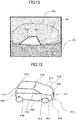
- FIG. 1 depicts a top plan view of a dump truck according to the present embodiment.
- the dump truck 1 depicted in this figure includes: a vehicle body frame 2; front wheels 3 (3L ad 3R) and rear wheels 4 (4L and 4R) attached for rotation to the vehicle body frame 2; a vessel 5 attached for upward and downward movement above the vehicle body frame 2; monocular cameras 6 (6a, 6b, 6c and 6d) fixed to a chassis, the vehicle body frame 2 or the like; a cab 7 provided at a front upper portion of the vehicle body frame 2; an image processing apparatus 10 incorporated in an arbitrary place (for example, in the inside of the cab 7) on the vehicle body frame 2; and a display apparatus 100 provided in the inside of the cab 7.
- the vehicle body frame 2 forms a main body of the dump truck 1 and has the front wheels 3 and the rear wheels 4 at front and rear portions thereof.
- the front wheel 3R is a front wheel on the right side of the vehicle
- the front wheel 3L is a front wheel on the left side of the vehicle.
- the rear wheels 4R are two rear wheels on the right side of the vehicle
- the rear wheels 4L are two rear wheels on the left side of the vehicle.
- the vessel 5 is a so-called loading platform and is utilized to load sediment, mineral or the like. It is to be noted that the arrangement and the number of the front wheels 3 and the rear wheels 4 depicted are a mere example.
- the monocular cameras 6 that are image pickup apparatus can be installed at arbitrary positions of the dump truck 1.
- the totaling four cameras 6a, 6b, 6c and 6d are installed, and the camera 6a is installed in an obliquely downwardly looking down manner at a front upper portion of the dump truck 1 such that it has a visual field range 11 (range of a broken line 11 of FIG. 1 ) that includes a vehicle front 15a.
- the camera 6b is installed at a right side upper portion of the vehicle such that a visual field range 12 thereof includes a vehicle right side 15b.
- the camera 6c is installed at a rear upper portion of the vehicle such that a visual field range 13 thereof includes a vehicle rear 15c, and the camera 6d is installed at a left side upper portion of the vehicle such that a visual field range 14 thereof includes a vehicle left side 15d.
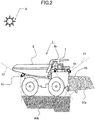
- FIG. 2 depicts a side elevational view of the dump truck 1 depicted in FIG. 1 .
- the camera 6a having the visual field range 11 (range of a broken line 11 of FIG. 2 ) is attached at a position obliquely rightwardly forwards as viewed from the cab 7, and the camera 6b having the visual field range 12 (range of a broken line 12 of FIG. 2 ) is attached at a position obliquely rightwardly rearwards as viewed from the cab 7. Further, the camera 6c having the visual field range 13 (range of a broken line 13 of FIG. 2 ) is attached to a rear portion of the vehicle body frame 2. Although the camera 6d having the visual field range 12 (not depicted in FIG.
- the cab 7 includes various operation means for operating the dump truck 1 by an operator boarded in the cab 7 including a steering handle, an accelerator pedal and a brake pedal. As another operation means, for example, a shift lever for causing the dump truck 1 to move forwardly or rearwardly is available.
- the image processing apparatus 10 and the display apparatus 100 are provided in the cab 7, and image data picked up and generated by the cameras 6a, 6b, 6c and 6d are subjected to a predetermined image process by the image processing apparatus 10.
- the image data for which the image process is performed are displayed on the display apparatus 100. Basically, videos picked up by the cameras 6a, 6b, 6c and 6d are displayed on the display apparatus 100.
- the forward visual field range 11 is a region at a obliquely forwardly downward location of the dump truck 1.
- the forward visual field range 11 sometimes includes an operator, a different working machine, a service car or the like. This similarly applies also to the rightward visual field range 12, rearward visual field range 13 and leftward visual field range 14.
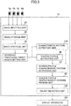
- FIG. 3 is a view depicting a general configuration of an image processing apparatus 10 according to a first embodiment of the present invention.
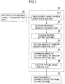
- the image processing apparatus 10 depicted in FIG. 3 includes an image inputting unit 20, an image storage unit 30, an image synthesis unit 35, a reference processing target region setting unit 80, a characteristic pattern extraction unit 170, a shadow profile extraction unit 40, a shadow profile characteristic pattern extraction unit 50, a shadow profile characteristic pattern masking unit 60 and an object detection unit 180.
- Camera images picked up by the four cameras 6a, 6b, 6c and 6d are individually inputted at predetermined sampling intervals to the image inputting unit 20 and stored into the image storage unit 30.
- the image storage unit 30 samples and stores input images from the image inputting unit 20 at different intervals from each other. For example, when the dump truck 1 is in a stopping state, the sampling interval is set longer, but when the dump truck 1 is moving, the sampling interval is set shorter, to store the input images. Therefore, image processing may be performed on the basis of required minimum input images, and reduction in time can be anticipated and optimization of processing can be anticipated.
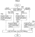
- the image synthesis unit 35 synthesizes a plurality of camera images outputted from the four cameras 6a, 6b, 6c and 6d and stored in the image storage unit 30 into one image.
- step 35a the image synthesis unit 35 decides from which one of the four cameras 6a, 6b, 6c and 6d an image originates. If the image originates from the forward camera 6a, then the image synthesis unit 35 performs a process for placing the image into a left upper region of an image processing screen (step 35b). If the image originates from the right side camera 6b, then the image synthesis unit 35 performs a process for placing the image into a right upper region of the image processing screen (step 35c).
- the image synthesis unit 35 performs a process for placing the image into a right lower region of the image processing screen (step 35d). If the image originates from the left side camera 6d, then the image synthesis unit 35 performs a process for placing the image into a left lower region of the image processing screen (step 35e). By this procedure, a synthesis image whose one frame is formed from the images of the four cameras 6a, 6b, 6c and 6d is created (step 35f).
- FIG. 5 An example of an image obtained by synthesizing with use of the image synthesis unit 35 an input image 20a of the camera 6a, an input image 20b of the camera 6b, an input image 20c of the camera 6c and an input image 20d of the camera 6d of the surroundings monitoring system for a working machine of the present invention is depicted in FIG. 5 .
- an own vehicle shadow 90a appears in the input image 20a
- another own vehicle shadow 90b appears in the input image 20b.
- a black vehicle 110 and a non-own vehicle shadow 111 exist as dark regions similarly to the own vehicle shadow 90a (for example, if the black vehicle lies below the working machine, then the black vehicle does not make a shadow (own vehicle shadow) of the working machine.
- the dark region is decided as an own vehicle shadow (own vehicle shadows 90a and 90b).
- a predetermined value that is a value that depends upon the magnitude of the working machine and the position of the sun 0
- the dark region is decided as an own vehicle shadow (own vehicle shadows 90a and 90b).
- the dark region has an area smaller than the predetermined value, then even if it contacts with part 15a or 15b of the working machine main body, this is decided as the non-own vehicle shadow 111.
- the reason why an own vehicle shadow and a non-own vehicle shadow are distinguished from each other in this manner is that, since, when a profile image of a shadow is generated by a shadow profile image creation unit 46 hereinafter described, the shadow profile characteristic pattern masking unit 60 excludes a profile image of a non-own vehicle shadow from a processing target region to make a mask region, it is intended to prevent such a situation that the mask region is expanded to degrade the obstacle detection performance.
- a region having an area smaller than the predetermined value is decided as a non-own vehicle shadow 111, since the working machine has a large machine body, also the area of the own vehicle shadow is frequently greater than that of a detection target object (for example, a service car), and it is rare that the area of the own vehicle shadow is smaller than a non-own vehicle shadow.
- a detection target object for example, a service car
- the reference processing target region setting unit 80 is a unit for specifying, on the basis of a processing target region set in advance, a region for which various succeeding processes (for example, including obstacle detection by the object detection unit 180) are to be performed on the images 20a, 20b, 20c and 20d synthesized by the image synthesis unit 35.
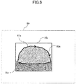
- FIG. 6 A setting procedure of a processing target region performed in advance before region specification by the reference processing target region setting unit 80 is performed is illustrated in FIG. 6 .
- a processing target region is set for the input image 20a picked up by the camera 6a. If an operator successively indicates reference points on the input image 20a manually with a mouse or the like to designate a closed region 81a in advance, then a processing target region 82a is created on the basis of the closed region 81a.
- a processing target region may be set automatically by image processing by utilization of profile information or the like or may be set by some other tool (for example, a tool for setting a road surface or the like extracted automatically from an image as a processing target region or a like tool).
- a processing target region to be set may be, for example, a closed region surrounded so as to include the entire ground or a closed region that surrounds part of the ground.
- the processing target region here is set only on the input image 20a, it is a matter of course that a processing target region may be set also on the other images 20b, 20c and 20d.
- the shadow profile extraction unit 40 is a unit that extracts a profile (shadow profile) of a region that can be regarded as a shadow of the dump truck 1 in a processing target region determined and set by the reference processing target region setting unit 80 on the basis of characteristic amounts of the image. It is to be noted that the "region that can be regarded as a shadow of the dump truck 1" need not coincide with an actual shadow region of the dump truck 1 but includes also a region that is recognized as a shadow of the dump truck 1 from the relationship of image processing. For example, where a black vehicle exists on the profile of a shadow of the dump truck 1, the profile of the black vehicle is sometimes regarded as a shadow of the dump truck 1.
- the shadow profile extraction unit 40 performs shadow profile extraction from one frame given as one image synthesized by the image synthesis unit 35.
- the shadow profile extraction unit 40 functions as a processing target region image creation unit 41, a shadow presence/absence decision unit 42, a shadow region extraction unit 43, an outline image creation unit 44 of a shadow region, an expansion image creation unit 45 and a shadow profile image creation unit 46.
- the processing target region image creation unit 41a generates, in an image stored in the image storage unit 30, a closed region set as a processing target region by the reference processing target region setting unit 80. Consequently, later processes are performed restrictively to the inside of the closed region.
- the shadow presence/absence decision unit 42 decides whether there exists a shadow in a processing target region. If the shadow presence/absence decision unit 42 decides that there exists a shadow, then the shadow region extraction unit 43 extracts a shadow region.
- the shadow presence/absence decision unit 42 decides whether there exists a shadow in a processing target region. If the shadow presence/absence decision unit 42 decides that there exists a shadow, then the shadow region extraction unit 43 extracts a shadow region.
- details of the shadow presence/absence decision unit 42 are described in detail with reference to FIG. 8 .
- FIG. 8 is a flow chart of processing executed by the shadow presence/absence decision unit 42 and the shadow region extraction unit 43 according to the surroundings monitoring system for a working machine of the present invention.
- the shadow presence/absence decision unit 42 performs a smoothing process for the processing target region of each of the images 20a, 20b, 20c and 20d to reduce noise.
- the shadow presence/absence decision unit 42 creates a luminance distribution diagram in the processing target region of each of the images 20a, 20b, 20c and 20d.
- the shadow presence/absence decision unit 42 checks the luminance distribution diagram created at step 42b and calculates the area of a region in which the luminance distribution is equal to or higher than a predetermined threshold value.
- the shadow presence/absence decision unit 42 decides whether the calculated area is smaller than a predetermined value, and if the calculated area is smaller than the predetermined value (including a case in which the area is zero), the shadow presence/absence decision unit 42 decides that there exists a shadow candidate at step 42e. On the other hand, if it is decided at step 42d that the calculated area is equal to or greater than the predetermined value, then the shadow presence/absence decision unit 42 decides at step 42k that there exists no own vehicle shadow and ends the processing.
- the shadow region extraction unit 43 determines a binary threshold value for extracting a shadow candidate region, and at step 42g, the shadow region extraction unit 43 performs a shaping process such as expansion or contraction for the binary image.
- the shadow region extraction unit 43 determines a region in which the area of a dark portion in the binary image is equal to or greater than a predetermined value as a shadow candidate region.
- the shadow region extraction unit 43 decides whether the shadow candidate region is close to an own vehicle region. If the shadow candidate region is in the proximity of the own vehicle region, then the shadow region extraction unit 43 decides at step 42j that there exists an own vehicle shadow and extracts the shadow candidate region as a shadow region, thereby ending the processing.
- the shadow region extraction unit 43 decides at step 42k that there exists no own vehicle shadow, thereby ending the processing.
- the shadow candidate region is positioned in the proximity of the own vehicle region at step 42i as described in depiction for FIG. 5 signifies that the dark region 90a that is an own vehicle shadow contacts with part 15a of the working machine main body.
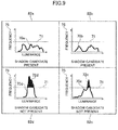
- FIG. 9 is an explanatory view of a luminance distribution diagram at step 42b in FIG. 8 .
- the frequency 75 indicates the number of pixels on which a luminance is present.
- luminance distribution diagrams 70a, 70b, 70c and 70d are created for the images 20a, 20b, 20c and 20d of the cameras 6a, 6b, 6c and 6d, respectively.
- an area in which the luminance distribution is equal to or greater than a predetermined binarization threshold value 71 for extracting a shadow within a reference processing target region is calculated, for example, with regard to the luminance distribution diagram 70a of the input image 20a of the camera 6a.
- a decision that "there exists a shadow candidate" is made. Where a shadow candidate exists in this manner, since the luminance is dispersed to a luminance of the bright ground and a luminance of the dark shadow, the luminance distribution diagram 70a includes no protrusion through the binarization threshold value 71.
- the luminance distribution diagram 70b of the input image 20b of the camera 6b similarly there exists no area in the portion in which the luminance distribution is equal to or higher than the binarization threshold value 71 in the reference processing target region, and therefore, a decision that "there exists a shadow region" is made.
- the portion 72c in which the luminance distribution is equal to or higher than the binarization threshold value 71 in the reference processing target region exists, and the area of the portion 72c is equal to or greater than the threshold value. Therefore, a decision that "there exists no own vehicle shadow" is made. Where a shadow candidate does not exist in this manner, the luminance of the ground occupies most part, and consequently, the luminance distribution diagram 70c includes a protrusion through the binarization threshold value 71.
- the area of portion 72d in which luminance distribution is equal to or higher than the binarization threshold value 71 in the reference processing target region is equal to or greater than the threshold value. Therefore, a decision that "there exists no own vehicle shadow" is made.
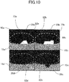
- FIG. 10 is a view depicting an outline of the own vehicle shadow 90a and the own vehicle shadow 90b created by the outline image creation unit 44 (refer to FIG. 7 ).
- the outline image creation unit 44 determines an outer line (profile line) of a region of the own vehicle shadow 90a extracted by the series of processes of FIG. 8 as an outline 73a of the own vehicle shadow 90a.
- the outline image creation unit 44 determines an outer line (profile line) of the region of the own vehicle shadow 90b as an outline 73b of the own vehicle shadow 90b.
- the expansion image creation unit 45 for an outline image of a shadow region performs an expansion process for an outline (shadow profile) of an outline image created by the outline image creation unit 44.
- the expansion process by the expansion image creation unit 45 is a process for providing a predetermined width to the outline in the outline image, and the width may be designated indirectly, for example, by designating an expansion time number.
- the expansion time number may be a requisite minimum number and may be one to three times.
- the shadow profile image creation unit 46 determines an outline image subjected to an expansion process by the expansion image creation unit 45 as a profile image of the shadow. Consequently, where a shadow appears in the image of the image storage unit 30, a profile of the shadow is extracted by the shadow profile extraction unit 40.
- the characteristic pattern extraction unit 170 extracts characteristic patterns in the images 20a, 20b, 20c and 20d on the basis of characteristic amounts in the images 20a, 20b, 20c and 20d, respectively.
- a characteristic pattern in a processing target region is extracted by the function of the reference processing target region setting unit 80.
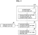
- FIG. 11 depicts a view in which peripheral elements of the characteristic pattern extraction unit 170 and the shadow profile characteristic pattern extraction unit 50 are extracted from FIG. 3 , and here, description is given taking a case in which a corner point is utilized as a characteristic pattern to be extracted by the characteristic pattern extraction unit 170 as an example.
- the characteristic pattern extraction unit 170 functions as a corner point extraction unit 51 and a characteristic pattern extraction unit 52 of a corner point group.
- the characteristic pattern to be extracted by the characteristic pattern extraction unit 170 may be any pattern indicating a shape of a characteristic of an image detected by extracting the characteristic on the basis of a characteristic amount. For example, a line-profile line (edge) or a region in place of or in addition to a corner point may be utilized.
- the corner point extraction unit 51 extracts corner points in an image by Harris corner detection or the like.
- the characteristic pattern extraction unit 52 of a corner point group extracts characteristic patterns of a corner point group formed from a plurality of corner points.
- FIGS. 12 and 13 are explanatory views of processing by the corner point extraction unit 51 and the characteristic pattern extraction unit 52.
- a corner point 51a and a corner point 51b (corner point group) existing at corner portions of the outline 73a are extracted as characteristic patterns. Meanwhile, in an example of a vehicle depicted in FIG.
- corner points since corner points exist in corners on a profile of the vehicle, a plurality of corner points 51A, 51B, 51C, 51D, 51E, 51F, 51G, 51H, 511, 51J, 51K, 51L, 51M, 51N and 51P are extracted. In short, the corner point group 51A to 51P is generated as characteristic patterns of the vehicle.
- the shadow profile characteristic pattern extraction unit 50 extracts a characteristic pattern (for example, a corner point) overlapping with a shadow profile.
- the shadow profile characteristic pattern extraction unit 50 extracts a characteristic pattern overlapping with a shadow profile image (image obtained by expanding an outline of a shadow) extracted by the shadow profile extraction unit 40 and determines the characteristic pattern as a shadow profile characteristic pattern.
- a corner point is used as a characteristic pattern in the present embodiment is that the number of corner points existing on a shadow has a tendency that it is relatively smaller than the number of corner points existing on a detection target object and it is easy to extract a shadow profile characteristic pattern.
- FIG. 14 is a flow chart of processing executed by the shadow profile characteristic pattern extraction unit 50.
- the shadow profile characteristic pattern extraction unit 50 decides whether there exists a characteristic pattern (corner point (characteristic point)) overlapping with a shadow profile image created by the shadow profile extraction unit 40. If it is decided at step 53e that there exists a characteristic pattern overlapping with the shadow profile, then the overlapping characteristic pattern is extracted at step 53f and determined as a shadow profile characteristic pattern (step 53g).
- step 53h if there exists no characteristic pattern overlapping with the shadow profile at step 53e, then it is determined that there exists no shadow profile characteristic pattern (step 53h).
- FIG. 15 is a view depicting an example of a characteristic pattern extracted at step 53f of FIG. 14 .
- a shadow profile image 53aa in FIG. 15 is obtained by an expansion process for the own vehicle shadow 90a. Since the corner point 51a and the corner point 51b overlap with the shadow profile image 53aa, the corner point 51a and the corner point 51b are determined as shadow profile characteristic patterns at step 53g.
- FIG. 16 is a view depicting a different example of a characteristic pattern extracted at step 53f of FIG. 14 .
- a shadow profile image 53bb in FIG. 16 is obtained by expansion of the own vehicle shadow 90b.
- a corner point 51e, a corner point 51f, a corner point 51g and a corner point 51h overlap with the shadow profile image 53bb and therefore, the corner point 51e, corner point 51f, corner point 51g and corner point 51h are determined as shadow profile characteristic patterns.
- FIG. 17 is a view depicting a further example of a characteristic pattern extracted at step 53f of FIG. 14 .
- a black vehicle advances into the own vehicle shadow 90b is described.
- the vehicle is regarded as a shadow, and an outline image S53a of a shadow region created by the outline image creation unit 44 of a shadow region (refer to FIG. 7 ) is subjected by a preset number of times to an expansion process by the expansion image creation unit 45 (refer to FIG. 7 ) to create an image 53dd.
- corner points 51A, 51B, 51C, 51D, 51E, 51F, 51G, 51H and 51P on a profile of the vehicle are extracted in addition to the corner point 51e on the shadow profile, and they are extracted as shadow profile characteristic patterns.
- the shadow profile characteristic pattern masking unit 60 creates a region in which characteristic patterns (shadow profile characteristic patterns) overlapping with a shadow profile are expanded and excludes the region (mask region) from the processing target region. Further, since the shadow profile characteristic patterns are extracted and excluded, not only misinformation of a shadow decreases, but also it becomes possible to optimize the processing region in the image process. If the mask region of the shadow profile characteristic pattern masking unit 60 is displayed on the display apparatus 100, then it becomes possible for the operator of the working machine to monitor the surroundings of the working machine without being influenced by misinformation of a shadow not only when the working machine stops but also when the working machine moves.
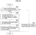
- FIG. 18 is a flow chart of processing executed by the shadow profile characteristic pattern masking unit 60.
- the shadow profile characteristic pattern masking unit 60 performs, at step 60a, decision of whether there exists a characteristic pattern overlapping with a shadow profile.
- step 60a If it is decided at step 60a that there exists a characteristic pattern overlapping with the shadow profile, then a process for expanding the extracted characteristic pattern by a predetermined number of times (approximately several times) is performed at step 60b.
- the expansion process is performed by expanding the characteristic pattern by approximately several times, and if Harris corner detection is used, a characteristic pattern is extracted by one pixel. Thus, it is sufficient that the characteristic pattern is expanded to be a mass having a diameter of approximately five to ten pixels.
- the expanded region is determined as a mask region, and at step 60d, a process of excluding the mask region as a mask portion from the processing target region is performed.
- step 60a if it is decided at step 60a that there exists no characteristic pattern overlapping with the shadow profile, then it is decided at step 60e that there exists no mask region.
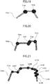
- FIG. 19 is a view depicting an example of an image in which the corner point 51a and the corner point 51b of FIG. 15 are expanded by a predetermined number of times (approximately several times) at step 60b by the shadow profile characteristic pattern masking unit 60. If the corner point 51a and the corner point 51b that are characteristic patterns on the shadow profile are subjected to an expansion process by approximately several times in eight directions or four directions, then a point 51aa expanded from the corner point 51a is generated and a point 51bb expanded from the corner point 51b is generated. The regions 51aa and 51bb are excluded as a mask portion from the processing target region (region for which obstacle detection is to be performed by the object detection unit 180) at step 60d.
- a profile of the shadow is extracted at every sampling interval, and characteristic patterns (regions 51aa and 51bb) positioned on the shadow profile are excluded from an obstacle detection target by the shadow profile characteristic pattern masking unit 60. Therefore, it can be prevented that the own vehicle shadow is recognized as an obstacle in error (misinformation of the shadow).
- FIG. 20 is a view depicting an example of an image in which the corner point 51e, corner point 51f, corner point 51g and corner point 51h of FIG. 16 are expanded by a predetermined number of times (approximately several times) at step 60b by the shadow profile characteristic pattern masking unit 60. If an expansion process is performed by approximately several times in eight directions or four directions for the corner point 51e that is a characteristic pattern on the shadow profile, then an expanded point 51ee is created. Also corner points 51ff, 51gg and 51hh are subjected to a similar expansion process, and the corner point 51ee, 51ff, 51gg and 51hh are used as mask portions and excluded from the processing target region.
- FIG. 21 is a view depicting an example of an image in which the corner point 51e and the corner points 51A, 51B, 51C, 51D, 51E, 51F, 51G, 51H and 51P of FIG. 17 are expanded by a predetermined number of times (approximately several times) at step 60b by the shadow profile characteristic pattern masking unit 60. If the corner point 51A that is a characteristic pattern on the shadow profile is subjected to an expansion process by approximately several times in eight directions or four directions, then an expanded point 51AA is created.
- corner point 51e and the corner points 51B, 51C, 51D, 51E, 51F, 51G, 51H and 51P are subjected to an expansion process similarly, and the corner points 51ee, 51AA and corner points 51BB, 51CC, 51DD, 51EE, 51FF, 51GG, 51HH and 51PP are excluded as mask portions from the processing target region.
- the object detection unit 180 can use the corner point 511, corner point 51J, corner point 51K, corner point 51L, corner point 51M and corner point 51N to immediately detect an obstacle in the own vehicle shadow (in the example of FIG. 17 , a vehicle). It is to be noted that it is a matter of course that the object depicted is nothing but an exemplary and also a different obstacle (for example, a person) from a vehicle can be detected similarly.
- an own vehicle shadow reflected in the image can be extracted without referring to a shadow boundary pattern stored in advance as in the prior art and further without using a color component. Therefore, the occurrence of false recognition of the own vehicle shadow is reduced and the processing speed and the work efficiency are improved.
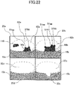
- FIG. 22 is a view depicting an example of a screen in which a region of a scene synthesized by the image synthesis unit 35 that is masked by the shadow profile characteristic pattern masking unit 60 is displayed on the display apparatus 100.
- a scene in which an input image 20a of the camera 6a, an input image 20b of the camera 6b, an input image 20c of the camera 6c and an input image 20d of the camera 6d are synthesized by the image synthesis unit 35 is displayed on the display apparatus 100.
- the corner points 51aa and 51bb are displayed as characteristic patterns excluded from the processing target on the input image 20a, and the corner points 51ee, 51ff, 51gg and 51hh are displayed on the input image 20b.
- the processing target region (obstacle detection target region) from which the shadow profile characteristic pattern is excluded is obvious, and the operator can confirm the processing target region on the real time basis.
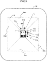
- FIGS. 23 and 24 depict examples in which a front portion of the dump truck 1 is displayed on the upper side, and the cab 7 is displayed at a left upper position with respect to the dump truck 1.
- FIG. 23 is a view depicting an example of a screen in which a region to be masked by the shadow profile characteristic pattern masking unit 60 is displayed in a bird's-eye view image 110 on the display apparatus 100.
- the region is displayed on the display apparatus 100 so as to be spread to the display region from the surroundings of the dump truck 1 to a remote distance (approximately 12 m).
- a bird's-eye view image 20aa of the input image 20a, a bird's-eye view image 20bb of the input image 20b, a bird's-eye view image 20cc of the input image 20c and a bird's-eye view image 20dd of the input image 20d are processing target regions, and the corner points 51aa and 51bb to be excluded from the processing target of the bird's-eye view image 20aa are displayed and the corner points 51ee, 51ff, 51gg and 51hh to be excluded from the processing target of the bird's-eye view image 20bb are displayed.
- a figure indicated at a central portion of the display apparatus 100 indicates the dump truck 1, and in addition to the figure, any other figure may be displayed if it indicates the dump truck 1.
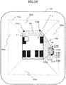
- FIG. 24 is a view depicting another example of a screen in which a region to be masked by the shadow profile characteristic pattern masking unit 60 is displayed in a bird's-eye view image 110 on the display apparatus 100.
- the display region is displayed on the display apparatus 100 restricting the same to a range from the surroundings of the dump truck 1 to a comparatively short distance (approximately 5 m).
- a comparatively short distance approximately 5 m.
- a black vehicle advances in the own vehicle shadow 90b in the bird's-eye view image 20bb of the input image 6bb, and corner points 51ee, 51AA, 51BB, 51CC, 51DD, 51EE, 51FF, 51GG, 51HH to be excluded from the processing target of the bird's-eye view image 20bb are displayed. Consequently, the object detection unit 180 detects the black vehicle as an obstacle on the basis of the remaining characteristic pattern other than the black vehicle, and a warning indication 190 indicating that an obstacle is approaching the dump truck 1 is displayed on the display screen 110.
- the warning indication 190 depicted is a rectangle defined so as to substantially contact with the outer shape of the characteristic pattern of the obstacle, and the operator can recognize the approach of the obstacle readily from the warning indication 190 displayed on the screen of the display apparatus 100.
- the shape of the warning indication 190 may be of a figure other than a rectangle, and the figure may be colored or the shape or the color of the figure may be changed as time passes.
- the display apparatus 100 plays a role of a notification device for the notification that an obstacle is detected by the object detection unit 180.
- a sound generation device for generating sound or a warning lamp may be utilized as a method for obstacle notification.
- FIG. 25 is a view depicting an example of a display screen of the display apparatus 100.
- the example of FIG. 25 is a view in which a bird's-eye view image 110 synthesized by the image synthesis unit 35 and an image (through image) 111 picked up by the rear camera 6c are displayed in parallel.
- a front portion of the dump truck 1 is displayed on the upper side, and the cab 7 is displayed at a left upper portion of the dump truck 1.
- the through image 211 originating from the rear camera 6c, the operator can discriminate an obstacle in the rear (vehicle 105) without a discomfort on the basis of the camera image familiar to the operator.
- the warning indication 190 is displayed on both of the bird's-eye view image 110 and the through image 211, and the operator can grasp approach of the vehicle 105 readily.
- FIG. 26 is a view depicting an example of a display screen of the display apparatus 100.
- a range from the surroundings of the dump truck 1 to a comparatively short distance (approximately 5 m) in a bird's-eye view image 112 synthesized by the image synthesis unit 35 is displayed on the display apparatus 100.
- a dump track 1a indicating the dump truck 1 is displayed greater than that in the case of FIG. 25 following up the display range.
- a front portion of the dump track 1a is disposed on the right side in the image, and the cab 7 is displayed at a right upper portion of the display screen. Since the display range is restricted to the proximity of the dump truck 1 and an obstacle (vehicle 105) existing in the proximity of the dump truck 1 is displayed large, the operator can clearly discriminate the most dangerous obstacle existing in the proximity of the dump truck 1.
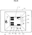
- FIG. 27 is a view depicting an example of a display screen of the display apparatus 100.
- a range from the surroundings of the dump truck 1 to a middle distance (approximately 8 m) in a bird's-eye view image 113 synthesized by the image synthesis unit 35 is displayed on the display apparatus 100.
- a figure 1b indicative of the dump truck 1 is displayed smaller than that in the case of FIG. 26 following up the display range.
- the operator can discriminate an obstacle (vehicle 105) existing at a position of a middle distance from the dump truck 1.
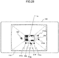
- FIG. 28 is a view depicting an example of a display screen of the display apparatus 100.
- a range of a bird's-eye view image 114 synthesized by the image synthesis unit 35 from the surroundings of the dump truck 1 to a remote distance is displayed on the display apparatus 100.
- a figure 1c indicative of the dump truck 1 is displayed in a smaller size than that in the case of FIG. 27 following up the display range.
- the operator can discriminate an obstacle (vehicle 105) existing at a position of a remote distance from the dump truck 1.
- FIG. 29 is a view depicting an example of a display screen of the display apparatus 100.
- a through image 116 of the right side camera 6b and a through image 115 of the left side camera 6d are displayed in parallel.
- the left and right through images 116 and 115 are displayed in this manner, discrimination of obstacles existing on the left and the right with respect to the dump truck 1 is facilitated, and therefore, discovery of an obstacle in such a case that the dump truck 1 turns to the left or the right is facilitated.
- FIG. 30 is a view depicting an example of a display screen of the display apparatus 100.
- a through image 117 of the rear camera 6c is displayed. Where the through image 117 of the rear is displayed in this manner, discovery of an obstacle that exists in the rear of the dump truck 1 and is most difficult to discover is facilitated.
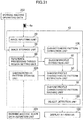
- FIG. 31 depicts a different example of a general configuration of the surroundings monitoring system for a working machine of the present invention.
- a working machine shape data definition unit 201 is an element in which shape data of the working machine is defined on the basis of specifications of the working machine.
- a characteristic pattern storage unit 200 extracts the shape data (appearance shape) defined by the working machine shape data definition unit 201 on the basis of the specifications of the working machine and stores the extracted shape data as a characteristic pattern indicative of the shape of the working machine.
- the appearance shape (shape data) here includes the total length, total width, total height, appearance uneven state and so forth of the working machine. However, the appearance shape may be information other than them if the information relates to the shape of the own vehicle shadow.
- the shadow profile characteristic pattern extraction unit 50 refers to a shadow profile image obtained by the shadow profile extraction unit 40 and the shape data stored in the characteristic pattern storage unit 200 to determine a characteristic pattern overlapping with the shadow profile image as a shadow profile characteristic pattern. It is to be noted that the shadow profile characteristic pattern extraction unit 50 may otherwise perform matching between a corner point group extracted by the characteristic pattern extraction unit 170 and the shape data stored in the characteristic pattern storage unit 200 and extract, if they are similar to each other with the matching rate between them equal to or higher than a predetermined value, then the shadow profile characteristic pattern extraction unit 50 extracts the corner point group as shadow profile characteristic patterns.
- an image from the image inputting unit 20 is inputted once to the image storage unit 30 upon activation of the working machine, then an operation situation of the working machine obtained on the basis of working machine running data 202 is thereafter checked. Then, if the working machine is not in a stopping state (is operating), then image is inputted from the image inputting unit 20 to the image storage unit 30. However, if the working machine is in a stopping state, inputting of an image from the image inputting unit 20 is interrupted. Consequently, an image from the image inputting unit 20 can be sampled at a sampling interval that varies in response to an operation situation of the working machine. Consequently, an image process may be performed on the basis of a minimum required number of input images, and decrease in time can be anticipated and optimization in process can be anticipated.
- an image from the image inputting unit 20 may be sampled after every fixed sampling interval.
- FIG. 32 is a flow chart of different processing executed by the shadow presence/absence decision unit 42 and the shadow region extraction unit 43 according to the surroundings monitoring apparatus for a working machine of the present invention. Processes like to those in the flow chart depicted in FIG. 8 are denoted by like reference characters and overlapping description of them is omitted herein.
- step 42bb in the flow chart of FIG. 32 a process for extracting a color component from within a reference processing target region of an image subjected to a smoothing process at step 42a is performed.
- step 42cc it is decided whether the reference processing target region is configured only from a region in which a color component exists.
- step 42cc If it is decided at step 42cc that there exists a region in which no color component exists, then the processing advances to step 42dd, at which the region in which there exists no color component is extracted. Then at step 42ee, a binary threshold value for extracting a shadow candidate region is determined to create a binary image, and the processes at steps beginning with step 42g are performed.
- step 42cc determines whether there exists only a region in which there exists a color component. If it is decided at step 42cc that there exists only a region in which there exists a color component, then a process at step 42k is performed. Where it is possible to use a color component to discriminate a shadow in this manner, the accuracy in decision of a shadow can be improved.
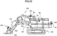
- FIG. 33 is a side elevational view of a large size hydraulic excavator of the loader type that is one of working machines that make a target of application of the present invention.
- the hydraulic excavator includes a lower travel structure 155, an upper swing structure 156 provided for swinging motor on the lower travel structure 155 through a swing structure bearing 157, and a front work implement 158 of the articulated type connected for upward and downward movement on the upper swing structure 156.
- a bucket 152 provided on the articulated front work implement 158 is disposed such that, in a ground contacting state, the opening thereof is directed forwardly, and a bucket opening/closing cylinder 164 is provided in such a manner as depicted in FIG. 33 on the bucket 152. Further, a boom cylinder 161, a bucket cylinder 162, an arm cylinder 163 and the bucket opening/closing cylinder 164 perform, through respective expanding and contracting movements thereof, boom raising/lowering, arm pushing/pulling, bucket clouding/dumping and bucket closing/opening. If a plurality of cameras (for example, cameras 6a, 6c and 6d) in FIG. 33 ) and the components described above beginning with the image processing apparatus 10 are incorporated in the hydraulic excavator configured in such a manner as described above, then a surroundings monitoring system can be configured similarly as in the case of the dump truck 1 described hereinabove.
- a surroundings monitoring system can be configured similarly as in the case of the dump truck 1 described hereinabove.
- the components of the image processing apparatus described above and the functions, execution processes and so forth of the components may be implemented partly or entirely by hardware (for example, logics for executing the functions are designed in an integrated circuit).
- the components of the image processing apparatus described above may be a program (software) that implements, by being read out and executed by an arithmetic processing unit (for example, a CPU), the functions relating to the components of the image processing apparatus.
- the information relating to the program can be stored into, for example, a semiconductor memory (flash memory, SSD or the like), a magnetic storage device (hard disk drive or the like), a recording medium (magnetic disk, optical disk or the like) or the like.
Landscapes
- Engineering & Computer Science (AREA)
- Physics & Mathematics (AREA)
- General Physics & Mathematics (AREA)
- Multimedia (AREA)
- Theoretical Computer Science (AREA)
- Computer Vision & Pattern Recognition (AREA)
- Mechanical Engineering (AREA)
- Mining & Mineral Resources (AREA)
- Civil Engineering (AREA)
- General Engineering & Computer Science (AREA)
- Structural Engineering (AREA)
- Signal Processing (AREA)
- Image Analysis (AREA)
- Image Processing (AREA)
- Closed-Circuit Television Systems (AREA)
- Traffic Control Systems (AREA)
Applications Claiming Priority (2)
| Application Number | Priority Date | Filing Date | Title |
|---|---|---|---|
| JP2014090679A JP6178280B2 (ja) | 2014-04-24 | 2014-04-24 | 作業機械の周囲監視装置 |
| PCT/JP2015/056432 WO2015163015A1 (ja) | 2014-04-24 | 2015-03-04 | 作業機械の周囲監視装置 |
Publications (3)
| Publication Number | Publication Date |
|---|---|
| EP3136341A1 EP3136341A1 (en) | 2017-03-01 |
| EP3136341A4 EP3136341A4 (en) | 2018-01-03 |
| EP3136341B1 true EP3136341B1 (en) | 2020-03-04 |
Family
ID=54332186
Family Applications (1)
| Application Number | Title | Priority Date | Filing Date |
|---|---|---|---|
| EP15782523.3A Active EP3136341B1 (en) | 2014-04-24 | 2015-03-04 | Surroundings monitoring system for working machine |
Country Status (5)
| Country | Link |
|---|---|
| US (1) | US10160383B2 (OSRAM) |
| EP (1) | EP3136341B1 (OSRAM) |
| JP (1) | JP6178280B2 (OSRAM) |
| CN (1) | CN106062823B (OSRAM) |
| WO (1) | WO2015163015A1 (OSRAM) |
Families Citing this family (26)
| Publication number | Priority date | Publication date | Assignee | Title |
|---|---|---|---|---|
| WO2017094627A1 (ja) * | 2015-11-30 | 2017-06-08 | 住友重機械工業株式会社 | 作業機械用周辺監視システム |
| JP6572156B2 (ja) * | 2016-03-02 | 2019-09-04 | 株式会社神戸製鋼所 | 建設機械の干渉防止装置 |
| JP6729146B2 (ja) * | 2016-08-03 | 2020-07-22 | コベルコ建機株式会社 | 障害物検出装置 |
| JP6599835B2 (ja) * | 2016-09-23 | 2019-10-30 | 日立建機株式会社 | 鉱山用作業機械、障害物判別装置、及び障害物判別方法 |
| JP6855254B2 (ja) * | 2017-01-12 | 2021-04-07 | 株式会社デンソーテン | 画像処理装置、画像処理システム、及び、画像処理方法 |
| WO2018151280A1 (ja) * | 2017-02-17 | 2018-08-23 | 住友重機械工業株式会社 | 作業機械用周辺監視システム |
| JP6589945B2 (ja) * | 2017-07-14 | 2019-10-16 | コベルコ建機株式会社 | 建設機械 |
| JP7003994B2 (ja) * | 2017-08-08 | 2022-01-21 | ソニーグループ株式会社 | 画像処理装置および方法 |
| JP6969983B2 (ja) | 2017-11-10 | 2021-11-24 | 株式会社小松製作所 | ダンプトラック |
| JP6900897B2 (ja) * | 2017-12-25 | 2021-07-07 | コベルコ建機株式会社 | 建設機械の障害物検出装置 |
| EP3779054B1 (en) * | 2018-03-26 | 2023-10-18 | Sumitomo (S.H.I.) Construction Machinery Co., Ltd. | Excavator |
| JP7160606B2 (ja) * | 2018-09-10 | 2022-10-25 | 株式会社小松製作所 | 作業機械の制御システム及び方法 |
| WO2020089984A1 (ja) * | 2018-10-29 | 2020-05-07 | 株式会社Pfu | 画像処理装置、制御方法及び制御プログラム |
| GB2582323B (en) * | 2019-03-19 | 2022-02-09 | Jaguar Land Rover Ltd | Image processing system and method |
| CN110099268B (zh) * | 2019-05-28 | 2021-03-02 | 吉林大学 | 色彩自然匹配与显示区自然融合的盲区透视化显示方法 |
| US10949685B2 (en) | 2019-07-22 | 2021-03-16 | Caterpillar Inc. | Excluding a component of a work machine from a video frame based on motion information |
| JP7310526B2 (ja) * | 2019-10-14 | 2023-07-19 | 株式会社デンソー | 障害物識別装置および障害物識別プログラム |
| US11320830B2 (en) | 2019-10-28 | 2022-05-03 | Deere & Company | Probabilistic decision support for obstacle detection and classification in a working area |
| JP7065068B2 (ja) * | 2019-12-13 | 2022-05-11 | 本田技研工業株式会社 | 車両周囲監視装置、車両、車両周囲監視方法およびプログラム |
| CN111462220B (zh) * | 2020-04-03 | 2025-01-24 | 深圳前海微众银行股份有限公司 | 待侦测物体阴影面积提取方法、装置、设备及介质 |
| CN115298394B (zh) * | 2020-05-29 | 2025-02-25 | 日立建机株式会社 | 作业机械 |
| JP6991285B2 (ja) * | 2020-07-28 | 2022-01-12 | 株式会社クボタ | 作業車 |
| JP7739042B2 (ja) * | 2021-05-14 | 2025-09-16 | ヤンマーホールディングス株式会社 | 安全監視システムの制御方法及び安全監視システム |
| JP2023074040A (ja) * | 2021-11-17 | 2023-05-29 | コベルコ建機株式会社 | 監視エリア設定システム |
| US20230306707A1 (en) * | 2022-03-28 | 2023-09-28 | Hl Klemove Corp. | Around view monitoring system and the method thereof |
| US20250044764A1 (en) * | 2023-08-01 | 2025-02-06 | Caterpillar Inc. | Nuisance condition detection system |
Family Cites Families (19)
| Publication number | Priority date | Publication date | Assignee | Title |
|---|---|---|---|---|
| US7038577B2 (en) * | 2002-05-03 | 2006-05-02 | Donnelly Corporation | Object detection system for vehicle |
| US7084386B2 (en) * | 2003-05-02 | 2006-08-01 | International Business Machines Corporation | System and method for light source calibration |
| JP2005043324A (ja) * | 2003-07-25 | 2005-02-17 | Matsushita Electric Ind Co Ltd | 路面損傷状態点検方法及び路面損傷位置の特定方法 |
| US7720580B2 (en) * | 2004-12-23 | 2010-05-18 | Donnelly Corporation | Object detection system for vehicle |
| WO2006118076A1 (ja) * | 2005-04-28 | 2006-11-09 | Aisin Seiki Kabushiki Kaisha | 車両周辺監視システム |
| JP4956915B2 (ja) * | 2005-05-20 | 2012-06-20 | 日産自動車株式会社 | 映像表示装置及び映像表示方法 |
| JP4809019B2 (ja) * | 2005-08-31 | 2011-11-02 | クラリオン株式会社 | 車両用障害物検出装置 |
| JP4674179B2 (ja) * | 2006-03-30 | 2011-04-20 | 株式会社デンソーアイティーラボラトリ | 影認識方法及び影境界抽出方法 |
| CN101211408B (zh) * | 2006-12-29 | 2011-05-25 | 东软集团股份有限公司 | 车辆侧面图像识别方法及装置、车灯误识别检测和行驶安全预测方法 |
| JP4853444B2 (ja) * | 2007-09-28 | 2012-01-11 | 株式会社デンソー | 移動物体検出装置 |
| JP4876118B2 (ja) * | 2008-12-08 | 2012-02-15 | 日立オートモティブシステムズ株式会社 | 立体物出現検知装置 |
| CN102158684A (zh) * | 2010-02-12 | 2011-08-17 | 王炳立 | 具有图像增强功能的自适应场景图像辅助系统 |
| JP2011205513A (ja) * | 2010-03-26 | 2011-10-13 | Aisin Seiki Co Ltd | 車両周辺監視装置 |
| JP2011209896A (ja) * | 2010-03-29 | 2011-10-20 | Nec Corp | 障害物検知装置、障害物検知方法及び障害物検知プログラム |
| JP5722127B2 (ja) * | 2011-06-07 | 2015-05-20 | 株式会社小松製作所 | 作業車両の周辺監視装置 |
| WO2012169352A1 (ja) * | 2011-06-07 | 2012-12-13 | 株式会社小松製作所 | 作業車両の周辺監視装置 |
| JP5781978B2 (ja) * | 2012-05-22 | 2015-09-24 | 株式会社小松製作所 | ダンプトラック |
| KR101439052B1 (ko) * | 2013-09-05 | 2014-09-05 | 현대자동차주식회사 | 장애물 검출 장치 및 방법 |
| CN103544487B (zh) * | 2013-11-01 | 2019-11-22 | 扬州瑞控汽车电子有限公司 | 基于单目视觉的前车识别方法 |
-
2014
- 2014-04-24 JP JP2014090679A patent/JP6178280B2/ja not_active Expired - Fee Related
-
2015
- 2015-03-04 EP EP15782523.3A patent/EP3136341B1/en active Active
- 2015-03-04 WO PCT/JP2015/056432 patent/WO2015163015A1/ja not_active Ceased
- 2015-03-04 US US15/124,123 patent/US10160383B2/en active Active
- 2015-03-04 CN CN201580011783.6A patent/CN106062823B/zh not_active Expired - Fee Related
Non-Patent Citations (1)
| Title |
|---|
| None * |
Also Published As
| Publication number | Publication date |
|---|---|
| EP3136341A1 (en) | 2017-03-01 |
| EP3136341A4 (en) | 2018-01-03 |
| JP6178280B2 (ja) | 2017-08-09 |
| US20170018070A1 (en) | 2017-01-19 |
| US10160383B2 (en) | 2018-12-25 |
| WO2015163015A1 (ja) | 2015-10-29 |
| CN106062823B (zh) | 2019-04-02 |
| CN106062823A (zh) | 2016-10-26 |
| JP2015210602A (ja) | 2015-11-24 |
Similar Documents
| Publication | Publication Date | Title |
|---|---|---|
| EP3136341B1 (en) | Surroundings monitoring system for working machine | |
| EP2937811B1 (en) | Vehicle peripheral obstacle notification system | |
| CN105339061B (zh) | 周边监视系统、作业车辆以及周边监视方法 | |
| AU2014213529B2 (en) | Image display system | |
| JP5902990B2 (ja) | 自走式産業機械の画像処理装置 | |
| JP5995899B2 (ja) | 自走式産業機械の画像処理装置 | |
| CN105474635A (zh) | 作业机械的周围监视装置 | |
| AU2023202153B2 (en) | Apparatus for analyzing a payload being transported in a load carrying container of a vehicle | |
| US20200063401A1 (en) | Terrain Feed Forward Calculation | |
| JP6072064B2 (ja) | 自走式産業機械の画像処理装置および自走式産業機械の画像処理方法 | |
| JP6878221B2 (ja) | 作業機械の障害物検知システム | |
| US20140293047A1 (en) | System for generating overhead view of machine | |
| US20230011758A1 (en) | Work machine and control method for work machine | |
| JP6420657B2 (ja) | 作業機械およびその周囲監視装置 | |
| WO2021010467A1 (ja) | 作業車両の表示システムおよび作業車両の表示方法 | |
| JP6405422B2 (ja) | 作業機械の周囲監視装置 | |
| AU2018375585B2 (en) | Operator assistance vision system | |
| JP6868996B2 (ja) | 障害物検知システム及び建設機械 | |
| EA045770B1 (ru) | Устройство для анализа полезного груза, транспортируемого в грузовом контейнере транспортного средства |
Legal Events
| Date | Code | Title | Description |
|---|---|---|---|
| STAA | Information on the status of an ep patent application or granted ep patent |
Free format text: STATUS: THE INTERNATIONAL PUBLICATION HAS BEEN MADE |
|
| PUAI | Public reference made under article 153(3) epc to a published international application that has entered the european phase |
Free format text: ORIGINAL CODE: 0009012 |
|
| STAA | Information on the status of an ep patent application or granted ep patent |
Free format text: STATUS: REQUEST FOR EXAMINATION WAS MADE |
|
| 17P | Request for examination filed |
Effective date: 20161124 |
|
| AK | Designated contracting states |
Kind code of ref document: A1 Designated state(s): AL AT BE BG CH CY CZ DE DK EE ES FI FR GB GR HR HU IE IS IT LI LT LU LV MC MK MT NL NO PL PT RO RS SE SI SK SM TR |
|
| AX | Request for extension of the european patent |
Extension state: BA ME |
|
| DAV | Request for validation of the european patent (deleted) | ||
| DAX | Request for extension of the european patent (deleted) | ||
| REG | Reference to a national code |
Ref country code: DE Ref legal event code: R079 Ref document number: 602015048220 Country of ref document: DE Free format text: PREVIOUS MAIN CLASS: G06T0007000000 Ipc: E02F0009260000 |
|
| A4 | Supplementary search report drawn up and despatched |
Effective date: 20171201 |
|
| RIC1 | Information provided on ipc code assigned before grant |
Ipc: G08G 1/16 20060101ALI20171127BHEP Ipc: G06T 7/00 20170101ALI20171127BHEP Ipc: H04N 7/18 20060101ALI20171127BHEP Ipc: E02F 9/26 20060101AFI20171127BHEP |
|
| GRAP | Despatch of communication of intention to grant a patent |
Free format text: ORIGINAL CODE: EPIDOSNIGR1 |
|
| STAA | Information on the status of an ep patent application or granted ep patent |
Free format text: STATUS: GRANT OF PATENT IS INTENDED |
|
| INTG | Intention to grant announced |
Effective date: 20190924 |
|
| RIN1 | Information on inventor provided before grant (corrected) |
Inventor name: KAWAMATA YUKIHIRO Inventor name: ONUMA CHIEKO Inventor name: KOWATARI YOICHI Inventor name: FUKUDA YOSHIBUMI Inventor name: OOTA MORITAKA Inventor name: YUMIBA RYO |
|
| GRAS | Grant fee paid |
Free format text: ORIGINAL CODE: EPIDOSNIGR3 |
|
| GRAA | (expected) grant |
Free format text: ORIGINAL CODE: 0009210 |
|
| STAA | Information on the status of an ep patent application or granted ep patent |
Free format text: STATUS: THE PATENT HAS BEEN GRANTED |
|
| AK | Designated contracting states |
Kind code of ref document: B1 Designated state(s): AL AT BE BG CH CY CZ DE DK EE ES FI FR GB GR HR HU IE IS IT LI LT LU LV MC MK MT NL NO PL PT RO RS SE SI SK SM TR |
|
| RAP1 | Party data changed (applicant data changed or rights of an application transferred) |
Owner name: HITACHI CONSTRUCTION MACHINERY CO., LTD. |
|
| REG | Reference to a national code |
Ref country code: GB Ref legal event code: FG4D |
|
| REG | Reference to a national code |
Ref country code: CH Ref legal event code: EP |
|
| REG | Reference to a national code |
Ref country code: AT Ref legal event code: REF Ref document number: 1240492 Country of ref document: AT Kind code of ref document: T Effective date: 20200315 |
|
| REG | Reference to a national code |
Ref country code: DE Ref legal event code: R096 Ref document number: 602015048220 Country of ref document: DE |
|
| REG | Reference to a national code |
Ref country code: IE Ref legal event code: FG4D |
|
| PG25 | Lapsed in a contracting state [announced via postgrant information from national office to epo] |
Ref country code: NO Free format text: LAPSE BECAUSE OF FAILURE TO SUBMIT A TRANSLATION OF THE DESCRIPTION OR TO PAY THE FEE WITHIN THE PRESCRIBED TIME-LIMIT Effective date: 20200604 Ref country code: FI Free format text: LAPSE BECAUSE OF FAILURE TO SUBMIT A TRANSLATION OF THE DESCRIPTION OR TO PAY THE FEE WITHIN THE PRESCRIBED TIME-LIMIT Effective date: 20200304 Ref country code: RS Free format text: LAPSE BECAUSE OF FAILURE TO SUBMIT A TRANSLATION OF THE DESCRIPTION OR TO PAY THE FEE WITHIN THE PRESCRIBED TIME-LIMIT Effective date: 20200304 |
|
| REG | Reference to a national code |
Ref country code: NL Ref legal event code: MP Effective date: 20200304 |
|
| PG25 | Lapsed in a contracting state [announced via postgrant information from national office to epo] |
Ref country code: BG Free format text: LAPSE BECAUSE OF FAILURE TO SUBMIT A TRANSLATION OF THE DESCRIPTION OR TO PAY THE FEE WITHIN THE PRESCRIBED TIME-LIMIT Effective date: 20200604 Ref country code: GR Free format text: LAPSE BECAUSE OF FAILURE TO SUBMIT A TRANSLATION OF THE DESCRIPTION OR TO PAY THE FEE WITHIN THE PRESCRIBED TIME-LIMIT Effective date: 20200605 Ref country code: LV Free format text: LAPSE BECAUSE OF FAILURE TO SUBMIT A TRANSLATION OF THE DESCRIPTION OR TO PAY THE FEE WITHIN THE PRESCRIBED TIME-LIMIT Effective date: 20200304 Ref country code: SE Free format text: LAPSE BECAUSE OF FAILURE TO SUBMIT A TRANSLATION OF THE DESCRIPTION OR TO PAY THE FEE WITHIN THE PRESCRIBED TIME-LIMIT Effective date: 20200304 Ref country code: HR Free format text: LAPSE BECAUSE OF FAILURE TO SUBMIT A TRANSLATION OF THE DESCRIPTION OR TO PAY THE FEE WITHIN THE PRESCRIBED TIME-LIMIT Effective date: 20200304 |
|
| REG | Reference to a national code |
Ref country code: LT Ref legal event code: MG4D |
|
| PG25 | Lapsed in a contracting state [announced via postgrant information from national office to epo] |
Ref country code: NL Free format text: LAPSE BECAUSE OF FAILURE TO SUBMIT A TRANSLATION OF THE DESCRIPTION OR TO PAY THE FEE WITHIN THE PRESCRIBED TIME-LIMIT Effective date: 20200304 |
|
| PG25 | Lapsed in a contracting state [announced via postgrant information from national office to epo] |
Ref country code: ES Free format text: LAPSE BECAUSE OF FAILURE TO SUBMIT A TRANSLATION OF THE DESCRIPTION OR TO PAY THE FEE WITHIN THE PRESCRIBED TIME-LIMIT Effective date: 20200304 Ref country code: LT Free format text: LAPSE BECAUSE OF FAILURE TO SUBMIT A TRANSLATION OF THE DESCRIPTION OR TO PAY THE FEE WITHIN THE PRESCRIBED TIME-LIMIT Effective date: 20200304 Ref country code: SK Free format text: LAPSE BECAUSE OF FAILURE TO SUBMIT A TRANSLATION OF THE DESCRIPTION OR TO PAY THE FEE WITHIN THE PRESCRIBED TIME-LIMIT Effective date: 20200304 Ref country code: IS Free format text: LAPSE BECAUSE OF FAILURE TO SUBMIT A TRANSLATION OF THE DESCRIPTION OR TO PAY THE FEE WITHIN THE PRESCRIBED TIME-LIMIT Effective date: 20200704 Ref country code: CZ Free format text: LAPSE BECAUSE OF FAILURE TO SUBMIT A TRANSLATION OF THE DESCRIPTION OR TO PAY THE FEE WITHIN THE PRESCRIBED TIME-LIMIT Effective date: 20200304 Ref country code: RO Free format text: LAPSE BECAUSE OF FAILURE TO SUBMIT A TRANSLATION OF THE DESCRIPTION OR TO PAY THE FEE WITHIN THE PRESCRIBED TIME-LIMIT Effective date: 20200304 Ref country code: EE Free format text: LAPSE BECAUSE OF FAILURE TO SUBMIT A TRANSLATION OF THE DESCRIPTION OR TO PAY THE FEE WITHIN THE PRESCRIBED TIME-LIMIT Effective date: 20200304 Ref country code: PT Free format text: LAPSE BECAUSE OF FAILURE TO SUBMIT A TRANSLATION OF THE DESCRIPTION OR TO PAY THE FEE WITHIN THE PRESCRIBED TIME-LIMIT Effective date: 20200729 Ref country code: SM Free format text: LAPSE BECAUSE OF FAILURE TO SUBMIT A TRANSLATION OF THE DESCRIPTION OR TO PAY THE FEE WITHIN THE PRESCRIBED TIME-LIMIT Effective date: 20200304 |
|
| REG | Reference to a national code |
Ref country code: CH Ref legal event code: PL |
|
| REG | Reference to a national code |
Ref country code: AT Ref legal event code: MK05 Ref document number: 1240492 Country of ref document: AT Kind code of ref document: T Effective date: 20200304 |
|
| REG | Reference to a national code |
Ref country code: DE Ref legal event code: R097 Ref document number: 602015048220 Country of ref document: DE |
|
| REG | Reference to a national code |
Ref country code: BE Ref legal event code: MM Effective date: 20200331 |
|
| PG25 | Lapsed in a contracting state [announced via postgrant information from national office to epo] |
Ref country code: LU Free format text: LAPSE BECAUSE OF NON-PAYMENT OF DUE FEES Effective date: 20200304 Ref country code: MC Free format text: LAPSE BECAUSE OF FAILURE TO SUBMIT A TRANSLATION OF THE DESCRIPTION OR TO PAY THE FEE WITHIN THE PRESCRIBED TIME-LIMIT Effective date: 20200304 |
|
| PLBE | No opposition filed within time limit |
Free format text: ORIGINAL CODE: 0009261 |
|
| STAA | Information on the status of an ep patent application or granted ep patent |
Free format text: STATUS: NO OPPOSITION FILED WITHIN TIME LIMIT |
|
| PG25 | Lapsed in a contracting state [announced via postgrant information from national office to epo] |
Ref country code: CH Free format text: LAPSE BECAUSE OF NON-PAYMENT OF DUE FEES Effective date: 20200331 Ref country code: DK Free format text: LAPSE BECAUSE OF FAILURE TO SUBMIT A TRANSLATION OF THE DESCRIPTION OR TO PAY THE FEE WITHIN THE PRESCRIBED TIME-LIMIT Effective date: 20200304 Ref country code: LI Free format text: LAPSE BECAUSE OF NON-PAYMENT OF DUE FEES Effective date: 20200331 Ref country code: IT Free format text: LAPSE BECAUSE OF FAILURE TO SUBMIT A TRANSLATION OF THE DESCRIPTION OR TO PAY THE FEE WITHIN THE PRESCRIBED TIME-LIMIT Effective date: 20200304 Ref country code: IE Free format text: LAPSE BECAUSE OF NON-PAYMENT OF DUE FEES Effective date: 20200304 Ref country code: AT Free format text: LAPSE BECAUSE OF FAILURE TO SUBMIT A TRANSLATION OF THE DESCRIPTION OR TO PAY THE FEE WITHIN THE PRESCRIBED TIME-LIMIT Effective date: 20200304 |
|
| 26N | No opposition filed |
Effective date: 20201207 |
|
| PG25 | Lapsed in a contracting state [announced via postgrant information from national office to epo] |
Ref country code: BE Free format text: LAPSE BECAUSE OF NON-PAYMENT OF DUE FEES Effective date: 20200331 Ref country code: SI Free format text: LAPSE BECAUSE OF FAILURE TO SUBMIT A TRANSLATION OF THE DESCRIPTION OR TO PAY THE FEE WITHIN THE PRESCRIBED TIME-LIMIT Effective date: 20200304 Ref country code: PL Free format text: LAPSE BECAUSE OF FAILURE TO SUBMIT A TRANSLATION OF THE DESCRIPTION OR TO PAY THE FEE WITHIN THE PRESCRIBED TIME-LIMIT Effective date: 20200304 |
|
| GBPC | Gb: european patent ceased through non-payment of renewal fee |
Effective date: 20200604 |
|
| PG25 | Lapsed in a contracting state [announced via postgrant information from national office to epo] |
Ref country code: GB Free format text: LAPSE BECAUSE OF NON-PAYMENT OF DUE FEES Effective date: 20200604 Ref country code: FR Free format text: LAPSE BECAUSE OF NON-PAYMENT OF DUE FEES Effective date: 20200504 |
|
| PGFP | Annual fee paid to national office [announced via postgrant information from national office to epo] |
Ref country code: DE Payment date: 20220203 Year of fee payment: 8 |
|
| PG25 | Lapsed in a contracting state [announced via postgrant information from national office to epo] |
Ref country code: TR Free format text: LAPSE BECAUSE OF FAILURE TO SUBMIT A TRANSLATION OF THE DESCRIPTION OR TO PAY THE FEE WITHIN THE PRESCRIBED TIME-LIMIT Effective date: 20200304 Ref country code: MT Free format text: LAPSE BECAUSE OF FAILURE TO SUBMIT A TRANSLATION OF THE DESCRIPTION OR TO PAY THE FEE WITHIN THE PRESCRIBED TIME-LIMIT Effective date: 20200304 Ref country code: CY Free format text: LAPSE BECAUSE OF FAILURE TO SUBMIT A TRANSLATION OF THE DESCRIPTION OR TO PAY THE FEE WITHIN THE PRESCRIBED TIME-LIMIT Effective date: 20200304 |
|
| PG25 | Lapsed in a contracting state [announced via postgrant information from national office to epo] |
Ref country code: MK Free format text: LAPSE BECAUSE OF FAILURE TO SUBMIT A TRANSLATION OF THE DESCRIPTION OR TO PAY THE FEE WITHIN THE PRESCRIBED TIME-LIMIT Effective date: 20200304 Ref country code: AL Free format text: LAPSE BECAUSE OF FAILURE TO SUBMIT A TRANSLATION OF THE DESCRIPTION OR TO PAY THE FEE WITHIN THE PRESCRIBED TIME-LIMIT Effective date: 20200304 |
|
| REG | Reference to a national code |
Ref country code: DE Ref legal event code: R119 Ref document number: 602015048220 Country of ref document: DE |
|
| PG25 | Lapsed in a contracting state [announced via postgrant information from national office to epo] |
Ref country code: DE Free format text: LAPSE BECAUSE OF NON-PAYMENT OF DUE FEES Effective date: 20231003 |