EP2937811B1 - Vehicle peripheral obstacle notification system - Google Patents
Vehicle peripheral obstacle notification system Download PDFInfo
- Publication number
- EP2937811B1 EP2937811B1 EP15161667.9A EP15161667A EP2937811B1 EP 2937811 B1 EP2937811 B1 EP 2937811B1 EP 15161667 A EP15161667 A EP 15161667A EP 2937811 B1 EP2937811 B1 EP 2937811B1
- Authority
- EP
- European Patent Office
- Prior art keywords
- image
- obstacle
- moving obstacle
- composite
- image formation
- Prior art date
- Legal status (The legal status is an assumption and is not a legal conclusion. Google has not performed a legal analysis and makes no representation as to the accuracy of the status listed.)
- Not-in-force
Links
- 230000002093 peripheral effect Effects 0.000 title claims description 76
- 239000002131 composite material Substances 0.000 claims description 84
- 238000001514 detection method Methods 0.000 claims description 71
- 230000015572 biosynthetic process Effects 0.000 claims description 43
- 238000000034 method Methods 0.000 claims description 18
- 235000004522 Pentaglottis sempervirens Nutrition 0.000 claims description 17
- 230000008569 process Effects 0.000 claims description 17
- 238000000605 extraction Methods 0.000 claims description 14
- 240000004050 Pentaglottis sempervirens Species 0.000 claims description 13
- 239000000284 extract Substances 0.000 claims description 11
- 230000000717 retained effect Effects 0.000 claims description 6
- 241000905137 Veronica schmidtiana Species 0.000 claims description 4
- 238000006243 chemical reaction Methods 0.000 description 14
- 230000000694 effects Effects 0.000 description 7
- 238000010276 construction Methods 0.000 description 6
- 239000011435 rock Substances 0.000 description 4
- 238000010586 diagram Methods 0.000 description 2
- 238000009877 rendering Methods 0.000 description 2
- 238000009412 basement excavation Methods 0.000 description 1
- 230000008878 coupling Effects 0.000 description 1
- 238000010168 coupling process Methods 0.000 description 1
- 238000005859 coupling reaction Methods 0.000 description 1
- 230000006378 damage Effects 0.000 description 1
- 230000001419 dependent effect Effects 0.000 description 1
- 238000007598 dipping method Methods 0.000 description 1
- 239000000446 fuel Substances 0.000 description 1
- 238000003384 imaging method Methods 0.000 description 1
- 229910052500 inorganic mineral Inorganic materials 0.000 description 1
- 239000011707 mineral Substances 0.000 description 1
- 239000000203 mixture Substances 0.000 description 1
- 238000012986 modification Methods 0.000 description 1
- 230000004048 modification Effects 0.000 description 1
- 238000012806 monitoring device Methods 0.000 description 1
- 230000001105 regulatory effect Effects 0.000 description 1
Images


Classifications
-
- B—PERFORMING OPERATIONS; TRANSPORTING
- B60—VEHICLES IN GENERAL
- B60Q—ARRANGEMENT OF SIGNALLING OR LIGHTING DEVICES, THE MOUNTING OR SUPPORTING THEREOF OR CIRCUITS THEREFOR, FOR VEHICLES IN GENERAL
- B60Q9/00—Arrangement or adaptation of signal devices not provided for in one of main groups B60Q1/00 - B60Q7/00, e.g. haptic signalling
- B60Q9/008—Arrangement or adaptation of signal devices not provided for in one of main groups B60Q1/00 - B60Q7/00, e.g. haptic signalling for anti-collision purposes
-
- B—PERFORMING OPERATIONS; TRANSPORTING
- B60—VEHICLES IN GENERAL
- B60R—VEHICLES, VEHICLE FITTINGS, OR VEHICLE PARTS, NOT OTHERWISE PROVIDED FOR
- B60R1/00—Optical viewing arrangements; Real-time viewing arrangements for drivers or passengers using optical image capturing systems, e.g. cameras or video systems specially adapted for use in or on vehicles
- B60R1/20—Real-time viewing arrangements for drivers or passengers using optical image capturing systems, e.g. cameras or video systems specially adapted for use in or on vehicles
- B60R1/22—Real-time viewing arrangements for drivers or passengers using optical image capturing systems, e.g. cameras or video systems specially adapted for use in or on vehicles for viewing an area outside the vehicle, e.g. the exterior of the vehicle
- B60R1/23—Real-time viewing arrangements for drivers or passengers using optical image capturing systems, e.g. cameras or video systems specially adapted for use in or on vehicles for viewing an area outside the vehicle, e.g. the exterior of the vehicle with a predetermined field of view
- B60R1/27—Real-time viewing arrangements for drivers or passengers using optical image capturing systems, e.g. cameras or video systems specially adapted for use in or on vehicles for viewing an area outside the vehicle, e.g. the exterior of the vehicle with a predetermined field of view providing all-round vision, e.g. using omnidirectional cameras
-
- G—PHYSICS
- G06—COMPUTING; CALCULATING OR COUNTING
- G06T—IMAGE DATA PROCESSING OR GENERATION, IN GENERAL
- G06T11/00—2D [Two Dimensional] image generation
- G06T11/60—Editing figures and text; Combining figures or text
-
- G—PHYSICS
- G06—COMPUTING; CALCULATING OR COUNTING
- G06T—IMAGE DATA PROCESSING OR GENERATION, IN GENERAL
- G06T7/00—Image analysis
- G06T7/20—Analysis of motion
- G06T7/246—Analysis of motion using feature-based methods, e.g. the tracking of corners or segments
-
- G—PHYSICS
- G06—COMPUTING; CALCULATING OR COUNTING
- G06V—IMAGE OR VIDEO RECOGNITION OR UNDERSTANDING
- G06V20/00—Scenes; Scene-specific elements
- G06V20/50—Context or environment of the image
- G06V20/56—Context or environment of the image exterior to a vehicle by using sensors mounted on the vehicle
- G06V20/58—Recognition of moving objects or obstacles, e.g. vehicles or pedestrians; Recognition of traffic objects, e.g. traffic signs, traffic lights or roads
-
- B—PERFORMING OPERATIONS; TRANSPORTING
- B60—VEHICLES IN GENERAL
- B60R—VEHICLES, VEHICLE FITTINGS, OR VEHICLE PARTS, NOT OTHERWISE PROVIDED FOR
- B60R2300/00—Details of viewing arrangements using cameras and displays, specially adapted for use in a vehicle
- B60R2300/80—Details of viewing arrangements using cameras and displays, specially adapted for use in a vehicle characterised by the intended use of the viewing arrangement
- B60R2300/8093—Details of viewing arrangements using cameras and displays, specially adapted for use in a vehicle characterised by the intended use of the viewing arrangement for obstacle warning
-
- E—FIXED CONSTRUCTIONS
- E02—HYDRAULIC ENGINEERING; FOUNDATIONS; SOIL SHIFTING
- E02F—DREDGING; SOIL-SHIFTING
- E02F9/00—Component parts of dredgers or soil-shifting machines, not restricted to one of the kinds covered by groups E02F3/00 - E02F7/00
- E02F9/26—Indicating devices
- E02F9/261—Surveying the work-site to be treated
-
- G—PHYSICS
- G06—COMPUTING; CALCULATING OR COUNTING
- G06T—IMAGE DATA PROCESSING OR GENERATION, IN GENERAL
- G06T2207/00—Indexing scheme for image analysis or image enhancement
- G06T2207/10—Image acquisition modality
- G06T2207/10016—Video; Image sequence
-
- G—PHYSICS
- G06—COMPUTING; CALCULATING OR COUNTING
- G06T—IMAGE DATA PROCESSING OR GENERATION, IN GENERAL
- G06T2207/00—Indexing scheme for image analysis or image enhancement
- G06T2207/20—Special algorithmic details
- G06T2207/20212—Image combination
- G06T2207/20221—Image fusion; Image merging
-
- G—PHYSICS
- G06—COMPUTING; CALCULATING OR COUNTING
- G06T—IMAGE DATA PROCESSING OR GENERATION, IN GENERAL
- G06T2207/00—Indexing scheme for image analysis or image enhancement
- G06T2207/30—Subject of image; Context of image processing
- G06T2207/30248—Vehicle exterior or interior
- G06T2207/30252—Vehicle exterior; Vicinity of vehicle
- G06T2207/30261—Obstacle
Description
- The present invention relates to a vehicle peripheral obstacle notification system. More particularly, the invention relates to a vehicle peripheral obstacle notification system which, used on a construction machine such as a large-sized dump truck working at a mine, performs detection and notification of obstacles near the vehicle body so as to efficiently evade the contact with such nearby obstruction. A vehicle peripheral obstacle notification system as described in the preamble portion of the
patent claim 1 is known fromEP 2 570 556 A1 - There exists an under-vehicle image display control device that generates a bird's-eye image covering the surroundings of the vehicle, and displays an under-vehicle image together with an image of the vehicle itself in a transparent manner. In addition to onboard cameras such as a rearview camera for imaging the vehicle surroundings, there is provided an onboard under-vehicle camera positioned at the bottom of the vehicle rear to acquire an image immediately under the bottom of the host vehicle, thereby to improve the capability of real-time acquisition of an under-vehicle image along with its accuracy. When the host vehicle travels in reverse, the onboard under-vehicle camera detects whether there is an obstacle in the expected traveling area of the host vehicle. When detecting a moving object in the acquired image, the control device generates and displays a transparent bird's-eye image including a transparent image immediately under the vehicle based on the currently acquired under-vehicle image (e.g.,
JP-2006-279752-A -
EP 2631374 A1 describes a monitoring device for a machine periphery. It generates a bird's eye image including obstacles and further information on said obstacles. -
EP 2 570 556 A1 -
EP 2570556 A1 teaches the display of bird's eye images of variable scale and displaying in said images obstacles and further information on them as far as they are present there. Likewise, ranges are displayed. - For large-sized construction machines such as dump trucks working at mines, there is a wide space under the body of the host vehicle. To ensure safe work with construction machines in such a situation, it is important not only to detect whether there are no obstacles such as persons or other vehicles in the space under the vehicle body but also to identify any detected obstacle and make notification thereof. The measures to be taken if the detected obstacle is a rock, for example, are vastly different from the measures to be taken if the obstacle is a person.
- Generally, construction machines perform diverse kinds of work such as traveling and excavation on an unpaved rough terrain or on a ground surface where there are gravel, rocks, mud, and/or oil leaked from the machines. For this reason, if the above-mentioned known technique is applied to the construction machines, troubles may well be expected such as the inability to acquire images with poor visibility due to mud, oil, or dirt sticking to the lens of the onboard under-vehicle camera, or the destruction of the camera proper caused by scattering gravel or rock. If the onboard under-vehicle camera suffers from such poor visibility or is destroyed outright, it is impossible to detect or identify obstacles in the space under the vehicle body, with nothing appearing in the image being displayed. This can be a significant impediment to securing safety during work.
- The present invention has been made in view of the above circumstances. An object of the invention is to provide a vehicle peripheral obstacle notification system with an improved notification strategy for detected obstacles.
- This object is accomplished by the features of
claim 1. - Dependent claims are directed on features of preferred embodiments of the invention.
- According to the present invention, without recourse to an onboard under-vehicle camera, it is possible to detect and image a moving obstacle at a position not appearing in a composite bird's-eye view merged with a view immediately under the vehicle body and covering the surroundings of the host vehicle, the position and image of the moving obstacle being superimposed onto a display screen prompting the user to know quickly what kind of obstacle is detected at what location. This allows the user easily to determine how to deal with the detected moving obstacle. As a result, the efficiency of the entire work being done is improved.
- Further objects and advantages of the present invention will become apparent upon a reading of the following description and appended drawings in which:
-
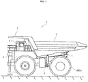
Fig. 1 is a side view showing a dump truck having a vehicle peripheral obstacle notification system as a first embodiment of the present invention; -
Fig. 2 is a conceptual view explaining the arrangement of cameras making up a surrounding image input part of the vehicle peripheral obstacle notification system as the first embodiment; -
Fig. 3 is a set of conceptual views showing images acquired by the cameras making up part of the vehicle peripheral obstacle notification system as the first embodiment; -
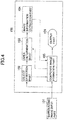
Fig. 4 is a block diagram showing a structure of the vehicle peripheral obstacle notification system as the first embodiment; -
Fig. 5 is a flowchart showing processing steps performed by the vehicle peripheral obstacle notification system as the first embodiment; -
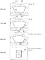
Figs. 6A, 6B, 6C, and 6D are conceptual views showing an example in which a moving obstacle is detected by the vehicle peripheral obstacle notification system as the first embodiment; -
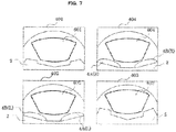
Fig. 7 is a set of conceptual views showing typical areas extracted from surrounding images acquired by the vehicle peripheral obstacle notification system as the first embodiment; -
Fig. 8 is a conceptual view showing how a composite image is typically displayed by the vehicle peripheral obstacle notification system as the first embodiment; -
Fig. 9 is a conceptual view explaining how an obstacle outside the image areas is typically detected by the vehicle peripheral obstacle notification system as the first embodiment; - 10 is a conceptual view explaining how an obstacle outside the image areas is typically detected by a vehicle peripheral obstacle notification system as a second embodiment of the present invention;
-
Fig. 11 is a flowchart showing the processing steps for highlight display performed by a vehicle peripheral obstacle notification system as a third embodiment of the present invention; -
Fig. 12 is a set of conceptual views explaining how an obstacle inside the image areas is typically detected by the vehicle peripheral obstacle notification system as the third embodiment; -
Fig. 13 is a conceptual view explaining how an obstacle under the host vehicle body is typically detected by a vehicle peripheral obstacle notification system as a fourth embodiment of the present invention; -
Fig. 14 is a flowchart showing the processing steps for highlight display performed by a vehicle peripheral obstacle notification system as a fifth embodiment of the present invention; and -
Fig. 15 is a set of conceptual views explaining how an obstacle moving from the surroundings of the host vehicle to under the host vehicle body is typically detected by the vehicle peripheral obstacle notification system as the fifth embodiment. - Some preferred embodiments of the present invention will now be explained with reference to the accompanying drawings through the use of examples in which the invention is applied to a dump truck, a large-sized transport vehicle that carries rubble, mineral ores, etc., excavated at a mine, for example. It should be noted that the application of the present invention is not limited to dump trucks.
-
Fig. 1 is a side view showing a dump truck having a vehicle peripheral obstacle notification system as the first embodiment of the present invention. A dump truck 1 (host vehicle) 1 shown inFig. 1 is furnished primarily with avehicle body 2 made of a sturdy frame structure, a vessel (bed) 3 mounted tiltably on thevehicle body 2, and a leftfront wheel 4A(L) and a leftrear wheel 4B(L) attached to thevehicle body 2. - An engine (not shown) for driving the
rear wheels 4B is mounted on thevehicle body 2. Typically, the engine has an engine control unit (ECU), and the revolutions of the engine are controlled by command signals from the ECU regulating the flow rate of the fuel being supplied to the engine. - The
vessel 3 is provided to carry cargoes such as rubble and coupled tiltably to thevehicle body 2 via apin coupling part 5, among others. Under thevessel 3 are two tiltingcylinders 6 arranged in the direction of the vehicle width with a predetermined distance therebetween. Feeding and evacuating pressure to and from the tiltingcylinders 6 causes thecylinders 6 to extend and contract, thereby tilting thevessel 3. Also, acanopy 7 is provided above thevessel 3 toward the front. - The
canopy 7 has the function of protecting acabin 8 below (i.e., in front of the vehicle body 2) from scattering objects such as stones and rocks and also protecting thecabin 8 if the vehicle is overturned. Inside thecabin 8, there are provided a control device 100 (seeFig. 4 ) constituting the vehicle peripheral obstacle notification system, a steering wheel (not shown), an accelerator pedal (not shown), and a brake pedal (not shown). -
Fig. 2 is a conceptual view explaining the arrangement of cameras making up a surrounding image input part of the vehicle peripheral obstacle notification system as the first embodiment.Fig. 3 is a set of conceptual views showing images acquired by the cameras making up part of the vehicle peripheral obstacle notification system as the first embodiment. - In
Fig. 2 , the front side and the rear side of thevehicle body 2 of thedump truck 1 have afront side camera 301 and arear side camera 303 for acquiring wide-angle images of the front and the rear of thedump truck 1, respectively. The left side and the right side of thevehicle body 2 are furnished with aleft side camera 302 and aright side camera 304 for acquiring wide-angle images of the left and the right of thedump truck 1, respectively. Thesecameras 301 through 304 are mounted on the respective sides of thevehicle body 2 at a dipping angle so as to acquire mainly images of the respective ground surfaces. Also, aright front wheel 4A(R) and a leftrear wheel 4B(R) are attached to thevehicle body 2 of thedump truck 1. -
Fig. 3 shows typical surrounding images acquired by thecameras 301 through 304.Reference numeral 401 stands for a typical front side image acquired by thefront side camera 301; 402 denotes a typical left side image acquired by theleft side camera 302; 403 represents a typical rear side image acquired by therear side camera 303; and 404 indicates a typical right side image acquired by theright side camera 304. - The surrounding
images 401 through 404 are acquired as wide-angle images so that the landscape in the distance (i.e., horizon) looks curved in each image. Also, some of the nearby objects, such as part of thevehicle body 2, part of the right and leftfront wheels 4A(R) and 4A(L), and part of the right and leftrear wheels 4B(R) and 4B(L) appear in the lower portion of each image. Thefront side image 401,left side image 402,rear side image 403, andright side image 404 are combined to make up the surrounding images for this embodiment. -
Fig. 4 is a block diagram showing a structure of the vehicle peripheral obstacle notification system implemented as the first embodiment. InFig. 4 , the vehicle peripheral obstacle notification system as the first embodiment includes a vehicle peripheralobstacle notification device 100 and a surroundingimage input part 101. - The surrounding
image input part 101 includes themultiple cameras 301 through 304 for acquiring images of the surroundings of thedump truck 1. The surroundingimage input part 101 transmits the multiple surroundingimages 401 through 404 acquired by the cameras to the vehicle peripheralobstacle notification device 100. - The vehicle peripheral
obstacle notification device 100 includes anobject detection part 102, anarea determination part 103, an imageinformation extraction part 104, a compositeimage formation part 105, and anoutput part 106. - The
object detection part 102 performs a detection process on the multiple surroundingimages 401 through 404 sent from the surroundingimage input part 101 so as to determine whether there is a moving obstacle in the images. Theobject detection part 102 outputs the result of the detection to thearea determination part 103 and compositeimage formation part 105. - When receiving a signal from the
object detection part 102 indicating the detection of a moving obstacle, thearea determination part 103 determines whether the moving obstacle is positioned inside or outside the image areas on the basis of position information such as the coordinates at which the moving obstacle is detected in a composite image from the compositeimage formation part 105. If the moving object is determined to be outside the image areas, thearea determination part 103 outputs the coordinates of the detected position to the imageinformation extraction part 104 along with the surrounding images. - On the basis of the coordinates of the detected position input from the
area determination part 103, the imageinformation extraction part 104 extracts the image corresponding to the detected position from the surrounding images. The imageinformation extraction part 104 outputs the extracted image as a detection result extracted image to the compositeimage formation part 105 together with the coordinates of the detected position. - The composite
image formation part 105 admits the multiple surroundingimages 401 through 404 sent from the surroundingimage input part 101, the signal from theobject detection part 102 indicating the detection of the moving obstacle, and a detected position coordinate signal from the imageinformation extraction part 104 indicating the position of the moving obstacle as well as the detection result extracted image. The compositeimage formation part 105 first converts the coordinate information about the detected moving obstacle into coordinates in a composite image, and outputs a signal representing the converted coordinates to thearea determination part 103. The compositeimage formation part 105 then extracts necessary portions from the input surrounding images for generating a composite bird's-eye image, superimposes the extracted portions on the images following the coordinate conversion, composes an extracted image of the detected position of the obstacle based on the input coordinates of the detected position, and outputs the composite image thus obtained to theoutput part 106. - The
output part 106 has a display unit that presents a user with the composite image input from the compositeimage formation part 105. - Explained next with reference to
Figs. 5 through 9 are the details of the processing for detecting and displaying the moving obstacle carried out by the vehicle peripheral obstacle notification system as the first embodiment of this invention.Fig. 5 is a flowchart showing processing steps performed by the vehicle peripheral obstacle notification system as the first embodiment.Figs. 6A, 6B, 6C, and 6D are conceptual views showing an example in which a moving obstacle is detected by the vehicle peripheral obstacle notification system as the first embodiment.Fig. 7 is a set of conceptual views showing typical areas extracted from the surrounding images acquired by the vehicle peripheral obstacle notification system as the first embodiment.Fig. 8 is a conceptual view showing how a composite image is typically displayed by the vehicle peripheral obstacle notification system as the first embodiment.Fig. 9 is a conceptual view explaining how an obstacle outside the image areas is typically detected by the vehicle peripheral obstacle notification system as the first embodiment. InFigs. 5 through 9 , the same reference numerals denote the same or corresponding components inFigs. 1 through 4 , so that their detailed explanations will be omitted hereunder. - In
Fig. 5 , the vehicle peripheralobstacle notification device 100 inputs surrounding images in step S201. Specifically, the vehicle peripheralobstacle notification device 100 inputs the surroundingimages 401 through 404 acquired by the surroundingimage input part 101. - The vehicle peripheral
obstacle notification device 100 performs the process of detecting an obstacle in step S202. Specifically, theobject detection part 102 shown inFig. 4 performs the process of detecting a moving obstacle. The images targeted for detection are thefront side image 401,left side image 402,rear side image 403, andright side image 404 input from the surroundingimage input part 101. - An example of the detection process is explained below with reference to
Figs. 6A through 6D. Figs. 6A through 6D depict a typical detection process in which an obstacle is detected from theleft side image 402.Fig. 6A is an image acquired at time t0-1 earlier than a specific time t0;Fig. 6B is an image acquired at the specific time t0;Fig. 6C is an image indicative of the result of obstacle detection; andFig. 6D is a detection result image. - Here,
Fig. 6A shows anobstacle 501 being imaged in theleft side image 402 at time t0-1, andFig. 6B indicates anobstacle 502 being imaged in theleft side image 402 at the specific time t0. Theobstacles left side camera 302 has acquired an image of the obstacle moving over time.Figs. 6A through 6C show that the person as the obstacle is standing between thefront wheel 4A(L) and therear wheel 4B(L). The image acquired in this situation shows the person with his head oriented downward in the image and his legs oriented upward. The head is shown proportionally larger than the legs because the head is positioned closer to the camera. - The
object detection part 102 inFig. 4 compares these images input from the surroundingimage input part 101 to calculate the portion where changes have occurred in the images over time. Adetection result 503 obtained through the calculation and indicated inFig. 6C as positioned outside the extracted areas (to be discussed later) retains the coordinate information relevant to theleft side image 402. If no changes have occurred in the images, the above detection result is not acquired. - Returning to
Fig. 5 , the vehicle peripheralobstacle notification device 100 determines in step S203 whether a moving object is detected in the detection process of step S202. If the moving object is determined to be detected, step S204 is reached; otherwise step S207 is reached. - The vehicle peripheral
obstacle notification device 100 calculates the coordinates of the detected position in step S204. Specifically, theobject detection part 102 shown inFig. 4 converts the position of the moving obstacle acquired in thefront side image 401,left side image 402,rear side image 403, andright side image 404 into coordinate information, and outputs a signal representative of the coordinate information to the compositeimage formation part 105. The compositeimage formation part 105 converts the input signal so as to calculate the coordinate information for a composite image. This conversion is the same as the process of forming the composite image in step S207, to be discussed later. Specifically, portions of thefront side image 401,left side image 402,rear side image 403, andright side image 404 are extracted and arranged in such a manner that their boundaries are contiguous with one another allowing the surroundings of the dump truck (host vehicle) 1 to be displayed. - This example is further explained with reference to
Figs. 7 and8 . A front side extractedarea 601, a left side extractedarea 602, a rear side extractedarea 603, and a right side extractedarea 604 are established, respectively, in the surroundingimages 401 through 404 shown inFig. 7 . These extracted areas are delineated on the basis of wide-angle camera characteristics and in such a manner that portions over a predetermined distance starting from immediately under thedump truck 1 are included in the images and that the extracted area in the image input from a given camera and the extracted area in the image input from the adjacent camera are contiguous with each other without overlaps. - The extracted
areas 601 through 604 are then subjected to coordinate conversion and image composition so as to form acomposite image 605 shown inFig. 8 . Within thecomposite image 605 ofFig. 8 , the front side extractedarea 601 is converted to a front side convertedimage 606. Likewise, the left side extractedarea 602 is converted to a left side convertedimage 607, the rear side extractedarea 603 to a rear side convertedimage 608, and the right side extractedarea 604 to a right side convertedimage 609. - In the
composite image 605, the convertedimages 606 through 609 are arranged successively to be contiguous with each other. With this embodiment, thecomposite image 605 is a bird's-eye view of the surroundings of thedump truck 1. In the portion where there is no image resulting from the coordinate conversion and image arrangement, ahost vehicle icon 610 is composed in order to give the user a clear indication of the area in which the dump truck (host vehicle) 1 is located. - Returning to
Fig. 5 , the vehicle peripheralobstacle notification device 100 determines in step S205 whether the coordinates of the detected position in step S204 are outside the areas of the converted images. Specifically, thearea determination part 103 determines whether the position of the moving obstacle is inside or outside the image areas on the basis of the position information including the detected position coordinates of the moving obstacle in the composite image from the compositeimage formation part 105. If the moving obstacle is determined to be outside the areas of the converted images, step S206 is reached; otherwise step S207 is reached. - With this embodiment, as shown in
Fig. 6C , theimage 503 indicative of the detection result outside the extracted areas is positioned inside theleft side image 402 but outside the left side extractedarea 602. When the coordinate information about the image is converted, the converted coordinate information points to the outside of the left side convertedimage 607 shown inFig. 8 . - Returning to
Fig. 5 , the vehicle peripheralobstacle notification device 100 extracts the image of the detected position in step S206. Specifically, from among the images yet to be converted, the imageinformation extraction part 104 extracts the image covering the portion corresponding to the detected position. With this embodiment, the imageinformation extraction part 104 extracts adetection result image 504 outside the extracted area and corresponding to thedetection result 503 that is inside theleft side image 402 and outside its extracted area inFig. 6D . Thedetection result image 504 thus extracted is retained by the compositeimage formation part 105. - If no moving obstacle is detected in step S203, if the moving obstacle is not found outside the areas of the converted images, or after the process of step S206 is carried out, the vehicle peripheral
obstacle notification device 100 forms the composite image in step S207. Specifically, step S207 is the process of forming the composite image as in the above-mentioned step S204. Portions of thefront side image 401,left side image 402,rear side image 403, andright side image 404 are extracted, subjected to coordinate conversion, and arranged by the compositeinformation formation part 105 in such a manner that their boundaries are contiguous with one another, thereby allowing the surroundings of the dump truck (host vehicle) 1 to be displayed. - Here, the processing by the composite
image formation part 105 following the execution of step S206 is different from the processing in other cases. If it is determined in step S203 that the moving obstacle is detected, this system retains the coordinate information from the detection result. Also, if it is determined in step S205 that the coordinates of the detection result are outside the image areas, this system retains thedetection result image 504 shown inFig. 6D . To present such information to the user, the compositeimage formation part 105 sets highlight display to thecomposite image 605 shown inFig. 9 . - Specifically, the composite
image formation part 105 converts thedetection result 503 outside the extracted area inFig. 6C , and sets thedetection result image 504 outside the extracted area at the converted coordinates. This allows thecomposite image 605 shown inFig. 9 to be superimposed with animage 701 in which the detection result outside the extracted area is arranged. If it is determined in step S205 that the coordinates of the detection result are inside the image area, another type of highlight display such as the rendering of a rectangle is made in that position, and thedetection result image 504 outside the extracted area is not used. This makes it possible to notify the user of the presence, by highlight display, of the moving obstacle not appearing in thecomposite image 605. - Returning to
Fig. 5 , the vehicle peripheralobstacle notification device 100 outputs the composite image in step S208. Specifically, the compositeimage formation part 105 outputs thecomposite image 605 to theoutput part 106. If the moving obstacle has been detected in the above-described process, what is output to theoutput part 106 is a highlightedcomposite image 605 such as thedetection result 701 following the coordinate conversion. - In step S209, the vehicle peripheral
obstacle notification device 100 determines whether the detection and the output of the moving obstacle are completed. If it is determined that these processes are completed, the vehicle peripheralobstacle notification device 100 terminates its processing; otherwise the vehicle peripheralobstacle notification device 100 returns to step S201. - When this embodiment performs the detection and notification of the moving obstacle in the manner described above, the user can be notified of what kind of obstacle is detected at what location. The details of the notification prompt the user to determine quickly what to do next in carrying out the work involved.
- According to the vehicle peripheral obstacle notification system as the first embodiment of the present invention, it is possible to detect, without recourse to an onboard under-vehicle camera, a moving obstacle at a location not appearing in a composite bird's-eye view covering the surroundings of the
host vehicle 1 including a view immediately under the vehicle body of thehost vehicle 1, the position and an image of the moving obstacle being superimposed onto a display screen prompting the user to know quickly what kind of obstacle is detected at what location. This allows the user easily to determine how to deal with the detected moving obstacle. As a result, the efficiency of the entire work being done is improved. - A vehicle peripheral obstacle notification system as the second embodiment of the present invention is explained below with reference to the accompanying drawings.
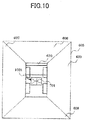
Fig. 10 is a conceptual view explaining how an obstacle outside the image areas is typically detected by the vehicle peripheral obstacle notification system as the second embodiment. InFig. 10 , the same reference numerals denote the same or corresponding components inFigs. 1 through 9 , so that their detailed explanations will be omitted hereunder. - The structure and the manner of operation of the vehicle peripheral obstacle notification system as the second embodiment are substantially the same as those of the first embodiment. The second embodiment differs from the first embodiment as follows: if a moving object is detected which is under the
host vehicle 1 and which does not appear in thecomposite image 605, the detected position is highlighted, and the image of the detection result (i.e., image of the obstacle) is indicated to the user as an image displayed at the center of thehost vehicle icon 610. - When highlight display is set in step S801, the
composite image 605 such as one shown inFig. 10 is output to theoutput part 106. Specifically, the compositeimage formation part 105 converts thedetection result 503 outside the extracted area, and sets highlight display at the converted coordinates for clearly indicating the detected position. In this example, anarrow 1001 pointing to the detected position is displayed from around the center of thehost vehicle icon 610 toward the converted coordinates. - Next, at the center of the
host vehicle icon 610, the compositeimage formation part 105 sets the rendering of theimage 701 in which the detection result outside the extracted area is arranged. If multiple moving obstacles are detected, this process is applied to the most recently detected moving obstacle. As a result of this, if the position at which the moving obstacle is detected is outside the areas of the converted images, simply looking at thehost vehicle icon 610 enables the user always to find theimage 701 in which the detection result outside the extracted areas is arranged. The user is thus allowed to minimize the movement of the point of view and thereby understand the situation quickly. - With the second embodiment, the position of the moving obstacle is displayed where it is detected, but the image of the detected obstacle is displayed at a position different from the detected position.
- The above-described vehicle peripheral obstacle notification system as the second embodiment of the invention provides substantially the same effects as the first embodiment explained above.
- Furthermore, the above-described vehicle peripheral obstacle notification system as the second embodiment enables the user to minimize the movement of the point of view when finding the image of the moving obstacle. As a result, the user can understand the situation quickly and ensure safety better than before.
- A vehicle peripheral obstacle notification system as the third embodiment of the present invention is explained below with reference to the accompanying drawings.
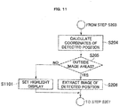
Fig. 11 is a flowchart showing the processing steps for highlight display performed by the vehicle peripheral obstacle notification system as the third embodiment.Fig. 13 is a set of conceptual views explaining how an obstacle inside the image areas is typically detected by the vehicle peripheral obstacle notification system as the third embodiment. InFigs. 11 and12 , the same reference numerals denote the same or corresponding components inFigs. 1 through 10 , so that their detailed explanations will be omitted hereunder. - The structure and the manner of operation of the vehicle peripheral obstacle notification system as the third embodiment are substantially the same as those of the first embodiment. The third embodiment differs from the first embodiment as follows: if a moving obstacle is detected in an area appearing in the
composite image 605, an image of the detection result (i.e., image of the obstacle) yet to be subjected to coordinate conversion is displayed for notification to the user. The flow of the processing by the third embodiment is similar to what is shown inFig. 5 but differs where another step is added after step S206. This difference is explained below with reference toFig. 11 . - In
Fig. 11 , if a moving obstacle is detected in step S203 and if the coordinates of the detection result are determined to be inside the image areas in step S205, step S1101 is carried out to set highlight display so that the user is presented with the detection result image in effect before application of the coordinate conversion and retained by this system. - Specifically, on the basis of the
left side image 402 shown on the left inFig. 12 , thecomposite image 605 indicated on the right inFig. 12 is formed. In this example, the moving obstacle is inside the left side extractedarea 602 and is shown as adetection result 1201 inside the extracted area. With the other embodiments discussed above, the detection result is subjected to coordinate conversion in step S207 in which the composite image is formed, and the result of the conversion is displayed on theoutput part 106. In this example, by contrast, coordinate conversion is not applied; the detection result is set within thecomposite image 605 as adetection result image 1202 inside the extracted area. - That makes it possible to set within the
composite image 605 the detection result image similar in appearance to theimage 701 in which the detection result outside the extracted areas is arranged. The user thus has less trouble in grasping the detection result. When the user is presented with the image not undergoing coordinate conversion, it is possible to display an image closely reflecting the state actually observed from where the camera is located. This allows the user easily to understand the situation on site. - The above-described vehicle peripheral obstacle notification system as the third embodiment of the invention provides substantially the same effects as the first embodiment explained above.
- Furthermore, the above-described vehicle peripheral obstacle notification system as the third embodiment enables the user to recognize the image closely reflecting the state actually observed from where the camera is located. As a result, the user can understand the situation on site quickly and ensure safety better than before.
- A vehicle peripheral obstacle notification system as the fourth embodiment of the present invention is explained below with reference to the accompanying drawings.
Fig. 13 is a conceptual view showing typical display of a composite bird's-eye image and a detected moving obstacle given by the vehicle peripheral obstacle notification system as the fourth embodiment. InFig. 13 , the same reference numerals denote the same or corresponding components inFigs. 1 through 12 , so that their detailed explanations will be omitted hereunder. - The structure and the manner of operation of the vehicle peripheral obstacle notification system as the fourth embodiment are substantially the same as those of the first embodiment. The fourth embodiment differs from the first embodiment as follows: if a moving object is detected which is under the
host vehicle 1 and which does not appear in thecomposite image 605, a partial area under thehost vehicle 1 is shown superimposed on thehost vehicle icon 610, along with the image of the detection result (i.e., image of the obstacle) for notification to the user. - When highlight display is set in step S801, the
composite image 605 such as one shown inFig. 13 is output to theoutput part 106. Specifically, the compositeimage formation part 105 converts thedetection result 503 outside the extracted area, and sets highlight display for clearly indicating the detected position at the converted coordinates. In this example, theimage 701 in which the detection result outside the extracted areas is arranged is displayed supplemented with a detection result surrounding image 1301 (shown shaded) indicating the surroundings of the detected position. - The detection
result surrounding image 1301 may be an image under thehost vehicle 1 included in the image containing the detected moving obstacle, for example. In this case, the detectionresult surrounding image 1301 corresponds to the portions other than the left side extractedarea 602 within theleft side image 402 shown inFig. 7 . Inside theleft side image 402, the underside of thehost vehicle 1 is located apparently at the bottom of the left side extractedarea 602. An image of this portion can thus be utilized inFig. 13 . - As the detection
result surrounding image 1301, either the image yet to be subjected to coordinate conversion or the image having undergone coordinate conversion may be set. Because the detection result and the situation of the surroundings can be displayed side by side, the user can easily estimate the cause and the future behavior of the detection result. - The above-described vehicle peripheral obstacle notification system as the fourth embodiment of the invention provides substantially the same effects as the first embodiment explained above.
- Furthermore, the above-described vehicle peripheral obstacle notification system as the fourth embodiment enables the user easily to estimate the cause and the future behavior of the detected moving obstacle. As a result, the user can understand the situation quickly and ensure safety better than before.
- A vehicle peripheral obstacle notification system as the fifth embodiment of the present invention is explained below with reference to the accompanying drawings.
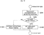
Fig. 14 is a flowchart showing the processing steps for highlight display performed by the vehicle peripheral obstacle notification system as the fifth embodiment.Fig. 15 is a set of conceptual views explaining how an obstacle inside the image areas is typically detected by the vehicle peripheral obstacle notification system as the fifth embodiment. InFig. 14 and15 , the same reference numerals denote the same or corresponding components inFigs. 1 through 13 , so that their detailed explanations will be omitted hereunder. - The structure and the manner of operation of the vehicle peripheral obstacle notification system as the fifth embodiment are substantially the same as those of the first embodiment. The fifth embodiment differs from the first embodiment as follows: if the moving object detected in the surroundings of the
host vehicle 1 has moved under thehost vehicle 1, an image acquired in the vehicle surroundings (i.e., image of the obstacle) is displayed at the under-vehicle location where there is the moving obstacle, for notification to the user. The flow of the processing by the sixth embodiment is similar to what is shown inFig. 5 but differs where another step is added after step S205. This difference is explained below with reference toFig. 14 . - In
Fig. 14 , if a moving obstacle is detected in step S203 and if the coordinates of the detection result are determined to be inside the image areas in step S205, step S1401 is carried out as a process to extract and retain a detection result image. If the coordinates of the detection result are determined to be outside the image areas in step S205, step S206 is replaced with step S1402 in which highlight display is set to present the user with the detection result image inside the image areas retained by this system. - Specifically, shown on the left in
Fig. 15 is theleft side image 402 in effect when the moving obstacle is still inside the left side extractedarea 602 that is the image area; on the right inFig. 15 is the composite image in effect when the moving obstacle later moved out of the image area. - If the moving object inside the image area is detected at a given point in time, step S1401 is carried out as a process to extract the detection result image. Specifically, the
detection result 1201 inside the extracted area shown on the left inFig. 15 is acquired, and is retained by the imageinformation extraction part 104. Thereafter, when the moving object has moved under thehost vehicle 1, the moving obstacle moves from inside the image area to the outside. At this time, the result of the determination of step S205 inFig. 14 is changed, and step S1402 is carried out as a process to set highlight display. - Specifically, as shown on the right in
Fig. 15 , theimage 701 is displayed in which the detection result outside the extracted area is displayed superimposed on thehost vehicle icon 610. The image used here was acquired in step S1401 and has been retained by the imageinformation extraction part 104. - Because it is possible to display an image closely reflecting the state of the moving obstacle visibly recognizable by the user's naked eye, the user can easily understand the situation on site. The image thus acquired is expected to be higher in brightness than if the detection result image is acquired from under the
host vehicle 1 where incident light is less than in the surroundings, so that the images acquired from the underside are expected to be relatively dark. The display therefore allows the user easily to grasp the behavior of the moving obstacle even if the obstacle has moved under thehost vehicle 1. - The above-described vehicle peripheral obstacle notification system as the fifth embodiment of the invention provides substantially the same effects as the first embodiment explained above.
- Furthermore, the above-described vehicle peripheral obstacle notification system as the fifth embodiment can display an image closely reflecting the state of the moving obstacle visibly recognizable by the user's naked eye, allowing the user easily to grasp the situation on site. As a result, the user can understand the situation quickly and ensure safety better than before.
- Although the above embodiments of the present invention have been explained by use of examples in which the invention is applied to the large-sized dump truck, this is not limitative of this invention. Alternatively, the invention may also be applied to large-sized machines at construction site and to large-sized work machines operating on disaster site.
- It is to be noted that the present invention is not limited to the aforementioned embodiments, but covers various modifications. While, for illustrative purposes, those embodiments have been described specifically, the present invention is not necessarily limited to the specific forms disclosed. Note also that some or all of the aforementioned components, functions, processors, and the like can be implemented by hardware such as an integrated circuit or the like. Alternatively, those components, functions, and the like can be implemented by software as well.
Claims (4)
- A vehicle peripheral obstacle notification system comprising:a surrounding image input part that comprises plural cameras that acquire plural images of the surroundings of a vehicle and outputs the acquired surrounding images;a composite image formation part adapted to extract parts of the acquired surrounding images as composite image formation areas and compose a composite bird's-eye image as an output resulting from the extracted composite image formation areas;an output part adapted to present a user with the resulting bird's eye image outputted by the composite image formation part,an object detection part adapted to perform the process of detecting a moving obstacle in surrounding images and for determining its position coordinates; andan area determination part adapted to determine whether the determined position coordinates of a detected moving obstacle are inside or outside the composite image formation areas;characterized in that the vehicle peripheral obstacle notification system further includes:an image information extraction part adapted to, if the area determination part determines that the detected position coordinates of the moving obstacle is outside the composite image formation areas, extract information about the detected position of the moving obstacle, extract an image of the detected moving obstacle and output it to the composite image formation part,wherein the composite image formation part is adapted to superimpose the extracted image of the moving obstacle onto the composite bird's-eye image on the extracted position before outputting the image to the output part so that the image of the moving obstacle is displayed at the detected position of the moving obstacle.
- The vehicle peripheral obstacle notification system according to claim 1, wherein the image information extraction part is adapted to, if the area determination part determines that the detected position of the moving obstacle is inside the composite image formation areas, extract the information about the detected position of the moving obstacle, extract the image of the detected moving obstacle and output the extracted information and image to the composite image formation part, which is adapted to superimpose it onto the composite bird's-eye image.
- The vehicle peripheral obstacle notification system according to claim 1, wherein the image information extraction part is adapted to, if the area determination part determines that the detected position of the moving obstacle is outside the composite image formation areas and corresponds to an area of a space below the host vehicle, extract the information about the detected position of the moving obstacle, extract the surrounding image of the area of the space below the host vehicle including the detected position and output the extracted information and image to the composite image formation part; and
wherein the composite image formation part is adapted to superimpose the surrounding image onto the areas other than those indicated by the composite bird's-eye image corresponding to the space below the host vehicle and highlight the detected position of the moving obstacle when composing the surrounding images. - The vehicle peripheral obstacle notification system according to claim 1, wherein the image information extraction part is adapted to, if the area determination part determines that the detected position of the moving obstacle has changed from inside to outside the composite image formation areas, retain the image of the moving obstacle acquired inside the composite image formation areas; and
wherein, while the detected position of the moving obstacle remains outside the composite image formation areas, the image information extraction part is adapted to output the information about the detected position of the moving obstacle and the retained image of the moving obstacle acquired inside the composite image formation areas, to the composite image formation part for superimposition thereby onto the composite bird's-eye image.
Applications Claiming Priority (1)
| Application Number | Priority Date | Filing Date | Title |
|---|---|---|---|
| JP2014091571A JP6262068B2 (en) | 2014-04-25 | 2014-04-25 | Near-body obstacle notification system |
Publications (2)
| Publication Number | Publication Date |
|---|---|
| EP2937811A1 EP2937811A1 (en) | 2015-10-28 |
| EP2937811B1 true EP2937811B1 (en) | 2018-10-17 |
Family
ID=52807653
Family Applications (1)
| Application Number | Title | Priority Date | Filing Date |
|---|---|---|---|
| EP15161667.9A Not-in-force EP2937811B1 (en) | 2014-04-25 | 2015-03-30 | Vehicle peripheral obstacle notification system |
Country Status (4)
| Country | Link |
|---|---|
| US (1) | US9463741B2 (en) |
| EP (1) | EP2937811B1 (en) |
| JP (1) | JP6262068B2 (en) |
| CN (1) | CN105007449B (en) |
Families Citing this family (35)
| Publication number | Priority date | Publication date | Assignee | Title |
|---|---|---|---|---|
| JP5938292B2 (en) * | 2012-08-03 | 2016-06-22 | 日立建機株式会社 | Transportation vehicle monitoring device |
| DE102014107235A1 (en) * | 2014-05-22 | 2015-11-26 | Dr. Ing. H.C. F. Porsche Aktiengesellschaft | A method of displaying a vehicle environment on a display device; a display device; a system of a plurality of image capture units and a display device; a computer program |
| WO2016140016A1 (en) * | 2015-03-03 | 2016-09-09 | 日立建機株式会社 | Device for monitoring surroundings of vehicle |
| US10656265B2 (en) * | 2016-03-14 | 2020-05-19 | Hitachi Construction Machinery Co., Ltd. | Mining work machine |
| JP6595401B2 (en) * | 2016-04-26 | 2019-10-23 | 株式会社Soken | Display control device |
| EP3267419B1 (en) * | 2016-07-08 | 2021-11-10 | Volvo Car Corporation | Method and system for maintaining a database comprising reported traffic-affecting events |
| JP6730615B2 (en) * | 2016-07-12 | 2020-07-29 | 株式会社Jvcケンウッド | Vehicle display control device, vehicle display system, vehicle display control method and program |
| CN106503653B (en) * | 2016-10-21 | 2020-10-13 | 深圳地平线机器人科技有限公司 | Region labeling method and device and electronic equipment |
| US10268907B2 (en) * | 2017-01-11 | 2019-04-23 | GM Global Technology Operations LLC | Methods and systems for providing notifications on camera displays for vehicles |
| US20180201132A1 (en) * | 2017-01-13 | 2018-07-19 | Deere & Company | Mobile machine-user protocol system and method |
| US10936884B2 (en) * | 2017-01-23 | 2021-03-02 | Magna Electronics Inc. | Vehicle vision system with object detection failsafe |
| GB2559759B (en) * | 2017-02-16 | 2020-07-29 | Jaguar Land Rover Ltd | Apparatus and method for displaying information |
| JP6730613B2 (en) | 2017-02-28 | 2020-07-29 | 株式会社Jvcケンウッド | Overhead video generation device, overhead video generation system, overhead video generation method and program |
| JP6796518B2 (en) * | 2017-03-06 | 2020-12-09 | 日立建機株式会社 | Moving object detection system |
| JP7252137B2 (en) * | 2017-12-04 | 2023-04-04 | 住友重機械工業株式会社 | Perimeter monitoring device |
| JP6900897B2 (en) | 2017-12-25 | 2021-07-07 | コベルコ建機株式会社 | Obstacle detector for construction machinery |
| JP6802196B2 (en) * | 2018-01-09 | 2020-12-16 | 日立建機株式会社 | Transport vehicle |
| JP7304922B2 (en) * | 2018-02-01 | 2023-07-07 | アルパイン株式会社 | Perimeter monitoring system |
| US11756426B2 (en) * | 2018-07-23 | 2023-09-12 | Newtrax Holdings Inc | Method and system for acknowledging presence in a context-aware environment |
| JP7374602B2 (en) * | 2019-03-29 | 2023-11-07 | 日立建機株式会社 | work vehicle |
| CN113727883A (en) * | 2019-04-26 | 2021-11-30 | 住友建机株式会社 | Display device, shovel, and information processing device |
| US10949685B2 (en) | 2019-07-22 | 2021-03-16 | Caterpillar Inc. | Excluding a component of a work machine from a video frame based on motion information |
| US11814816B2 (en) | 2019-09-11 | 2023-11-14 | Deere & Company | Mobile work machine with object detection and machine path visualization |
| US11755028B2 (en) | 2019-09-11 | 2023-09-12 | Deere & Company | Mobile work machine with object detection using vision recognition |
| GB2588186A (en) * | 2019-10-11 | 2021-04-21 | Caterpillar Inc | System for monitoring surrounding area of cold planer |
| US11320830B2 (en) | 2019-10-28 | 2022-05-03 | Deere & Company | Probabilistic decision support for obstacle detection and classification in a working area |
| US10981507B1 (en) | 2019-11-07 | 2021-04-20 | Focused Technology Solutions, Inc. | Interactive safety system for vehicles |
| JP7290119B2 (en) * | 2020-01-24 | 2023-06-13 | トヨタ自動車株式会社 | vehicle alarm device |
| JP7319593B2 (en) * | 2020-02-13 | 2023-08-02 | トヨタ自動車株式会社 | Vehicle perimeter monitoring device |
| US11472416B2 (en) | 2020-04-30 | 2022-10-18 | Deere & Company | Multi-dimensional mobile machine path visualization and control system |
| JP2022014975A (en) * | 2020-07-08 | 2022-01-21 | トヨタ自動車株式会社 | Vehicle periphery monitoring device |
| CN111912418A (en) * | 2020-07-16 | 2020-11-10 | 知行汽车科技(苏州)有限公司 | Method, device and medium for deleting obstacles in non-driving area of mobile carrier |
| US11661722B2 (en) | 2020-11-19 | 2023-05-30 | Deere & Company | System and method for customized visualization of the surroundings of self-propelled work vehicles |
| CN113807163B (en) * | 2021-07-28 | 2023-12-19 | 中科云谷科技有限公司 | Pump truck support leg placement method, pump truck support leg placement device and storage medium |
| KR20230055722A (en) * | 2021-10-19 | 2023-04-26 | 현대모비스 주식회사 | A target detection system and method of a vehicle |
Citations (1)
| Publication number | Priority date | Publication date | Assignee | Title |
|---|---|---|---|---|
| US20140354813A1 (en) * | 2011-09-16 | 2014-12-04 | Hitachi Construction Machinery Co., Ltd. | Surroundings Monitoring Device for Work Machine |
Family Cites Families (16)
| Publication number | Priority date | Publication date | Assignee | Title |
|---|---|---|---|---|
| JP4556742B2 (en) | 2005-03-30 | 2010-10-06 | 株式会社デンソー | Vehicle direct image display control apparatus and vehicle direct image display control program |
| JP4846426B2 (en) * | 2006-04-20 | 2011-12-28 | パナソニック株式会社 | Vehicle perimeter monitoring device |
| JP4404103B2 (en) * | 2007-03-22 | 2010-01-27 | 株式会社デンソー | Vehicle external photographing display system and image display control device |
| JP4847913B2 (en) | 2007-03-30 | 2011-12-28 | 日立建機株式会社 | Work machine periphery monitoring device |
| JP2009253673A (en) * | 2008-04-07 | 2009-10-29 | Clarion Co Ltd | Vehicle circumstances display device |
| JP5068779B2 (en) * | 2009-02-27 | 2012-11-07 | 現代自動車株式会社 | Vehicle surroundings overhead image display apparatus and method |
| JP4951639B2 (en) | 2009-03-02 | 2012-06-13 | 日立建機株式会社 | Work machine with ambient monitoring device |
| JP5165631B2 (en) * | 2009-04-14 | 2013-03-21 | 現代自動車株式会社 | Vehicle surrounding image display system |
| US20110001819A1 (en) * | 2009-07-02 | 2011-01-06 | Sanyo Electric Co., Ltd. | Image Processing Apparatus |
| CN102577372B (en) * | 2009-09-24 | 2015-06-10 | 松下电器产业株式会社 | Driving support display device |
| WO2011158955A1 (en) | 2010-06-18 | 2011-12-22 | 日立建機株式会社 | Device for monitoring area around work machine |
| JP5667638B2 (en) | 2010-10-22 | 2015-02-12 | 日立建機株式会社 | Work machine periphery monitoring device |
| JP5483120B2 (en) * | 2011-07-26 | 2014-05-07 | アイシン精機株式会社 | Vehicle perimeter monitoring system |
| US8768583B2 (en) | 2012-03-29 | 2014-07-01 | Harnischfeger Technologies, Inc. | Collision detection and mitigation systems and methods for a shovel |
| JP5324690B1 (en) * | 2012-09-21 | 2013-10-23 | 株式会社小松製作所 | Work vehicle periphery monitoring system and work vehicle |
| JP5629740B2 (en) * | 2012-09-21 | 2014-11-26 | 株式会社小松製作所 | Work vehicle periphery monitoring system and work vehicle |
-
2014
- 2014-04-25 JP JP2014091571A patent/JP6262068B2/en active Active
-
2015
- 2015-03-13 CN CN201510112033.XA patent/CN105007449B/en not_active Expired - Fee Related
- 2015-03-19 US US14/662,746 patent/US9463741B2/en active Active
- 2015-03-30 EP EP15161667.9A patent/EP2937811B1/en not_active Not-in-force
Patent Citations (1)
| Publication number | Priority date | Publication date | Assignee | Title |
|---|---|---|---|---|
| US20140354813A1 (en) * | 2011-09-16 | 2014-12-04 | Hitachi Construction Machinery Co., Ltd. | Surroundings Monitoring Device for Work Machine |
Also Published As
| Publication number | Publication date |
|---|---|
| CN105007449A (en) | 2015-10-28 |
| JP6262068B2 (en) | 2018-01-17 |
| US9463741B2 (en) | 2016-10-11 |
| CN105007449B (en) | 2019-01-15 |
| JP2015210649A (en) | 2015-11-24 |
| US20150307024A1 (en) | 2015-10-29 |
| EP2937811A1 (en) | 2015-10-28 |
Similar Documents
| Publication | Publication Date | Title |
|---|---|---|
| EP2937811B1 (en) | Vehicle peripheral obstacle notification system | |
| CN106797450B (en) | Vehicle body external moving object detection device | |
| US8933797B2 (en) | Video-based warning system for a vehicle | |
| JP5529943B2 (en) | Work vehicle periphery monitoring system and work vehicle | |
| AU2014213529B2 (en) | Image display system | |
| WO2016002163A1 (en) | Image display device and image display method | |
| JP6385745B2 (en) | Mining work vehicle | |
| CN109204136B (en) | Peripheral image display control device | |
| US20120314072A1 (en) | Image generation apparatus | |
| US10866416B2 (en) | Display control device and display control method | |
| JP5926315B2 (en) | Work vehicle periphery monitoring system and work vehicle | |
| JP6339337B2 (en) | Moving object detection system around the vehicle | |
| JP5902990B2 (en) | Self-propelled industrial machine image processing device | |
| US20140293047A1 (en) | System for generating overhead view of machine | |
| JP6401141B2 (en) | Vehicle obstacle detection device | |
| JP6878221B2 (en) | Obstacle detection system for work machines | |
| JP5083142B2 (en) | Vehicle periphery monitoring device | |
| JP6741364B2 (en) | Vehicle peripheral image display device and vehicle peripheral image display method | |
| JP6796518B2 (en) | Moving object detection system | |
| JP6868996B2 (en) | Obstacle detection system and construction machinery | |
| JP2019121249A (en) | Transport vehicle | |
| JP5990237B2 (en) | Dump truck peripheral monitoring system and dump truck | |
| JP2019121250A (en) | Transport vehicle | |
| JP5115171B2 (en) | In-vehicle image processing apparatus and in-vehicle image display apparatus | |
| JP2009146133A (en) | Onboard image processing apparatus, and onboard image displaying apparatus |
Legal Events
| Date | Code | Title | Description |
|---|---|---|---|
| PUAI | Public reference made under article 153(3) epc to a published international application that has entered the european phase |
Free format text: ORIGINAL CODE: 0009012 |
|
| AK | Designated contracting states |
Kind code of ref document: A1 Designated state(s): AL AT BE BG CH CY CZ DE DK EE ES FI FR GB GR HR HU IE IS IT LI LT LU LV MC MK MT NL NO PL PT RO RS SE SI SK SM TR |
|
| AX | Request for extension of the european patent |
Extension state: BA ME |
|
| 17P | Request for examination filed |
Effective date: 20151006 |
|
| RBV | Designated contracting states (corrected) |
Designated state(s): AL AT BE BG CH CY CZ DE DK EE ES FI FR GB GR HR HU IE IS IT LI LT LU LV MC MK MT NL NO PL PT RO RS SE SI SK SM TR |
|
| STAA | Information on the status of an ep patent application or granted ep patent |
Free format text: STATUS: EXAMINATION IS IN PROGRESS |
|
| 17Q | First examination report despatched |
Effective date: 20170224 |
|
| GRAP | Despatch of communication of intention to grant a patent |
Free format text: ORIGINAL CODE: EPIDOSNIGR1 |
|
| STAA | Information on the status of an ep patent application or granted ep patent |
Free format text: STATUS: GRANT OF PATENT IS INTENDED |
|
| INTG | Intention to grant announced |
Effective date: 20180629 |
|
| GRAS | Grant fee paid |
Free format text: ORIGINAL CODE: EPIDOSNIGR3 |
|
| GRAA | (expected) grant |
Free format text: ORIGINAL CODE: 0009210 |
|
| STAA | Information on the status of an ep patent application or granted ep patent |
Free format text: STATUS: THE PATENT HAS BEEN GRANTED |
|
| AK | Designated contracting states |
Kind code of ref document: B1 Designated state(s): AL AT BE BG CH CY CZ DE DK EE ES FI FR GB GR HR HU IE IS IT LI LT LU LV MC MK MT NL NO PL PT RO RS SE SI SK SM TR |
|
| RAP1 | Party data changed (applicant data changed or rights of an application transferred) |
Owner name: HITACHI CONSTRUCTION MACHINERY CO., LTD. |
|
| REG | Reference to a national code |
Ref country code: GB Ref legal event code: FG4D |
|
| REG | Reference to a national code |
Ref country code: CH Ref legal event code: EP |
|
| REG | Reference to a national code |
Ref country code: IE Ref legal event code: FG4D |
|
| REG | Reference to a national code |
Ref country code: DE Ref legal event code: R096 Ref document number: 602015018149 Country of ref document: DE Ref country code: AT Ref legal event code: REF Ref document number: 1054850 Country of ref document: AT Kind code of ref document: T Effective date: 20181115 |
|
| REG | Reference to a national code |
Ref country code: NL Ref legal event code: MP Effective date: 20181017 |
|
| REG | Reference to a national code |
Ref country code: DE Ref legal event code: R082 Ref document number: 602015018149 Country of ref document: DE Representative=s name: MANITZ FINSTERWALD PATENT- UND RECHTSANWALTSPA, DE |
|
| REG | Reference to a national code |
Ref country code: LT Ref legal event code: MG4D |
|
| REG | Reference to a national code |
Ref country code: AT Ref legal event code: MK05 Ref document number: 1054850 Country of ref document: AT Kind code of ref document: T Effective date: 20181017 |
|
| PG25 | Lapsed in a contracting state [announced via postgrant information from national office to epo] |
Ref country code: NL Free format text: LAPSE BECAUSE OF FAILURE TO SUBMIT A TRANSLATION OF THE DESCRIPTION OR TO PAY THE FEE WITHIN THE PRESCRIBED TIME-LIMIT Effective date: 20181017 |
|
| PG25 | Lapsed in a contracting state [announced via postgrant information from national office to epo] |
Ref country code: FI Free format text: LAPSE BECAUSE OF FAILURE TO SUBMIT A TRANSLATION OF THE DESCRIPTION OR TO PAY THE FEE WITHIN THE PRESCRIBED TIME-LIMIT Effective date: 20181017 Ref country code: IS Free format text: LAPSE BECAUSE OF FAILURE TO SUBMIT A TRANSLATION OF THE DESCRIPTION OR TO PAY THE FEE WITHIN THE PRESCRIBED TIME-LIMIT Effective date: 20190217 Ref country code: NO Free format text: LAPSE BECAUSE OF FAILURE TO SUBMIT A TRANSLATION OF THE DESCRIPTION OR TO PAY THE FEE WITHIN THE PRESCRIBED TIME-LIMIT Effective date: 20190117 Ref country code: AT Free format text: LAPSE BECAUSE OF FAILURE TO SUBMIT A TRANSLATION OF THE DESCRIPTION OR TO PAY THE FEE WITHIN THE PRESCRIBED TIME-LIMIT Effective date: 20181017 Ref country code: ES Free format text: LAPSE BECAUSE OF FAILURE TO SUBMIT A TRANSLATION OF THE DESCRIPTION OR TO PAY THE FEE WITHIN THE PRESCRIBED TIME-LIMIT Effective date: 20181017 Ref country code: LV Free format text: LAPSE BECAUSE OF FAILURE TO SUBMIT A TRANSLATION OF THE DESCRIPTION OR TO PAY THE FEE WITHIN THE PRESCRIBED TIME-LIMIT Effective date: 20181017 Ref country code: HR Free format text: LAPSE BECAUSE OF FAILURE TO SUBMIT A TRANSLATION OF THE DESCRIPTION OR TO PAY THE FEE WITHIN THE PRESCRIBED TIME-LIMIT Effective date: 20181017 Ref country code: PL Free format text: LAPSE BECAUSE OF FAILURE TO SUBMIT A TRANSLATION OF THE DESCRIPTION OR TO PAY THE FEE WITHIN THE PRESCRIBED TIME-LIMIT Effective date: 20181017 Ref country code: BG Free format text: LAPSE BECAUSE OF FAILURE TO SUBMIT A TRANSLATION OF THE DESCRIPTION OR TO PAY THE FEE WITHIN THE PRESCRIBED TIME-LIMIT Effective date: 20190117 Ref country code: LT Free format text: LAPSE BECAUSE OF FAILURE TO SUBMIT A TRANSLATION OF THE DESCRIPTION OR TO PAY THE FEE WITHIN THE PRESCRIBED TIME-LIMIT Effective date: 20181017 |
|
| PG25 | Lapsed in a contracting state [announced via postgrant information from national office to epo] |
Ref country code: PT Free format text: LAPSE BECAUSE OF FAILURE TO SUBMIT A TRANSLATION OF THE DESCRIPTION OR TO PAY THE FEE WITHIN THE PRESCRIBED TIME-LIMIT Effective date: 20190217 Ref country code: SE Free format text: LAPSE BECAUSE OF FAILURE TO SUBMIT A TRANSLATION OF THE DESCRIPTION OR TO PAY THE FEE WITHIN THE PRESCRIBED TIME-LIMIT Effective date: 20181017 Ref country code: GR Free format text: LAPSE BECAUSE OF FAILURE TO SUBMIT A TRANSLATION OF THE DESCRIPTION OR TO PAY THE FEE WITHIN THE PRESCRIBED TIME-LIMIT Effective date: 20190118 Ref country code: AL Free format text: LAPSE BECAUSE OF FAILURE TO SUBMIT A TRANSLATION OF THE DESCRIPTION OR TO PAY THE FEE WITHIN THE PRESCRIBED TIME-LIMIT Effective date: 20181017 Ref country code: RS Free format text: LAPSE BECAUSE OF FAILURE TO SUBMIT A TRANSLATION OF THE DESCRIPTION OR TO PAY THE FEE WITHIN THE PRESCRIBED TIME-LIMIT Effective date: 20181017 |
|
| REG | Reference to a national code |
Ref country code: DE Ref legal event code: R097 Ref document number: 602015018149 Country of ref document: DE |
|
| PG25 | Lapsed in a contracting state [announced via postgrant information from national office to epo] |
Ref country code: IT Free format text: LAPSE BECAUSE OF FAILURE TO SUBMIT A TRANSLATION OF THE DESCRIPTION OR TO PAY THE FEE WITHIN THE PRESCRIBED TIME-LIMIT Effective date: 20181017 Ref country code: CZ Free format text: LAPSE BECAUSE OF FAILURE TO SUBMIT A TRANSLATION OF THE DESCRIPTION OR TO PAY THE FEE WITHIN THE PRESCRIBED TIME-LIMIT Effective date: 20181017 Ref country code: DK Free format text: LAPSE BECAUSE OF FAILURE TO SUBMIT A TRANSLATION OF THE DESCRIPTION OR TO PAY THE FEE WITHIN THE PRESCRIBED TIME-LIMIT Effective date: 20181017 |
|
| PLBE | No opposition filed within time limit |
Free format text: ORIGINAL CODE: 0009261 |
|
| STAA | Information on the status of an ep patent application or granted ep patent |
Free format text: STATUS: NO OPPOSITION FILED WITHIN TIME LIMIT |
|
| PG25 | Lapsed in a contracting state [announced via postgrant information from national office to epo] |
Ref country code: SM Free format text: LAPSE BECAUSE OF FAILURE TO SUBMIT A TRANSLATION OF THE DESCRIPTION OR TO PAY THE FEE WITHIN THE PRESCRIBED TIME-LIMIT Effective date: 20181017 Ref country code: EE Free format text: LAPSE BECAUSE OF FAILURE TO SUBMIT A TRANSLATION OF THE DESCRIPTION OR TO PAY THE FEE WITHIN THE PRESCRIBED TIME-LIMIT Effective date: 20181017 Ref country code: RO Free format text: LAPSE BECAUSE OF FAILURE TO SUBMIT A TRANSLATION OF THE DESCRIPTION OR TO PAY THE FEE WITHIN THE PRESCRIBED TIME-LIMIT Effective date: 20181017 Ref country code: SK Free format text: LAPSE BECAUSE OF FAILURE TO SUBMIT A TRANSLATION OF THE DESCRIPTION OR TO PAY THE FEE WITHIN THE PRESCRIBED TIME-LIMIT Effective date: 20181017 |
|
| 26N | No opposition filed |
Effective date: 20190718 |
|
| PG25 | Lapsed in a contracting state [announced via postgrant information from national office to epo] |
Ref country code: MC Free format text: LAPSE BECAUSE OF FAILURE TO SUBMIT A TRANSLATION OF THE DESCRIPTION OR TO PAY THE FEE WITHIN THE PRESCRIBED TIME-LIMIT Effective date: 20181017 Ref country code: SI Free format text: LAPSE BECAUSE OF FAILURE TO SUBMIT A TRANSLATION OF THE DESCRIPTION OR TO PAY THE FEE WITHIN THE PRESCRIBED TIME-LIMIT Effective date: 20181017 |
|
| REG | Reference to a national code |
Ref country code: CH Ref legal event code: PL |
|
| GBPC | Gb: european patent ceased through non-payment of renewal fee |
Effective date: 20190330 |
|
| PG25 | Lapsed in a contracting state [announced via postgrant information from national office to epo] |
Ref country code: LU Free format text: LAPSE BECAUSE OF NON-PAYMENT OF DUE FEES Effective date: 20190330 |
|
| REG | Reference to a national code |
Ref country code: BE Ref legal event code: MM Effective date: 20190331 |
|
| PG25 | Lapsed in a contracting state [announced via postgrant information from national office to epo] |
Ref country code: GB Free format text: LAPSE BECAUSE OF NON-PAYMENT OF DUE FEES Effective date: 20190330 Ref country code: LI Free format text: LAPSE BECAUSE OF NON-PAYMENT OF DUE FEES Effective date: 20190331 Ref country code: CH Free format text: LAPSE BECAUSE OF NON-PAYMENT OF DUE FEES Effective date: 20190331 Ref country code: IE Free format text: LAPSE BECAUSE OF NON-PAYMENT OF DUE FEES Effective date: 20190330 |
|
| PG25 | Lapsed in a contracting state [announced via postgrant information from national office to epo] |
Ref country code: BE Free format text: LAPSE BECAUSE OF NON-PAYMENT OF DUE FEES Effective date: 20190331 Ref country code: FR Free format text: LAPSE BECAUSE OF NON-PAYMENT OF DUE FEES Effective date: 20190331 |
|
| PG25 | Lapsed in a contracting state [announced via postgrant information from national office to epo] |
Ref country code: TR Free format text: LAPSE BECAUSE OF FAILURE TO SUBMIT A TRANSLATION OF THE DESCRIPTION OR TO PAY THE FEE WITHIN THE PRESCRIBED TIME-LIMIT Effective date: 20181017 |
|
| PG25 | Lapsed in a contracting state [announced via postgrant information from national office to epo] |
Ref country code: MT Free format text: LAPSE BECAUSE OF NON-PAYMENT OF DUE FEES Effective date: 20190330 |
|
| PG25 | Lapsed in a contracting state [announced via postgrant information from national office to epo] |
Ref country code: CY Free format text: LAPSE BECAUSE OF FAILURE TO SUBMIT A TRANSLATION OF THE DESCRIPTION OR TO PAY THE FEE WITHIN THE PRESCRIBED TIME-LIMIT Effective date: 20181017 |
|
| PG25 | Lapsed in a contracting state [announced via postgrant information from national office to epo] |
Ref country code: HU Free format text: LAPSE BECAUSE OF FAILURE TO SUBMIT A TRANSLATION OF THE DESCRIPTION OR TO PAY THE FEE WITHIN THE PRESCRIBED TIME-LIMIT; INVALID AB INITIO Effective date: 20150330 |
|
| REG | Reference to a national code |
Ref country code: DE Ref legal event code: R079 Ref document number: 602015018149 Country of ref document: DE Free format text: PREVIOUS MAIN CLASS: G06K0009000000 Ipc: G06V0010000000 |
|
| PGFP | Annual fee paid to national office [announced via postgrant information from national office to epo] |
Ref country code: DE Payment date: 20220203 Year of fee payment: 8 |
|
| PG25 | Lapsed in a contracting state [announced via postgrant information from national office to epo] |
Ref country code: MK Free format text: LAPSE BECAUSE OF FAILURE TO SUBMIT A TRANSLATION OF THE DESCRIPTION OR TO PAY THE FEE WITHIN THE PRESCRIBED TIME-LIMIT Effective date: 20181017 |
|
| REG | Reference to a national code |
Ref country code: DE Ref legal event code: R119 Ref document number: 602015018149 Country of ref document: DE |
|
| PG25 | Lapsed in a contracting state [announced via postgrant information from national office to epo] |
Ref country code: DE Free format text: LAPSE BECAUSE OF NON-PAYMENT OF DUE FEES Effective date: 20231003 |