EP3133310A1 - Dispositif d'embrayage double - Google Patents
Dispositif d'embrayage double Download PDFInfo
- Publication number
- EP3133310A1 EP3133310A1 EP15779222.7A EP15779222A EP3133310A1 EP 3133310 A1 EP3133310 A1 EP 3133310A1 EP 15779222 A EP15779222 A EP 15779222A EP 3133310 A1 EP3133310 A1 EP 3133310A1
- Authority
- EP
- European Patent Office
- Prior art keywords
- hydraulic pressure
- chamber
- clutch
- piston
- supply line
- Prior art date
- Legal status (The legal status is an assumption and is not a legal conclusion. Google has not performed a legal analysis and makes no representation as to the accuracy of the status listed.)
- Granted
Links
Images


Classifications
-
- F—MECHANICAL ENGINEERING; LIGHTING; HEATING; WEAPONS; BLASTING
- F16—ENGINEERING ELEMENTS AND UNITS; GENERAL MEASURES FOR PRODUCING AND MAINTAINING EFFECTIVE FUNCTIONING OF MACHINES OR INSTALLATIONS; THERMAL INSULATION IN GENERAL
- F16D—COUPLINGS FOR TRANSMITTING ROTATION; CLUTCHES; BRAKES
- F16D48/00—External control of clutches
- F16D48/02—Control by fluid pressure
- F16D48/0206—Control by fluid pressure in a system with a plurality of fluid-actuated clutches
-
- F—MECHANICAL ENGINEERING; LIGHTING; HEATING; WEAPONS; BLASTING
- F16—ENGINEERING ELEMENTS AND UNITS; GENERAL MEASURES FOR PRODUCING AND MAINTAINING EFFECTIVE FUNCTIONING OF MACHINES OR INSTALLATIONS; THERMAL INSULATION IN GENERAL
- F16D—COUPLINGS FOR TRANSMITTING ROTATION; CLUTCHES; BRAKES
- F16D21/00—Systems comprising a plurality of actuated clutches
- F16D21/02—Systems comprising a plurality of actuated clutches for interconnecting three or more shafts or other transmission members in different ways
- F16D21/06—Systems comprising a plurality of actuated clutches for interconnecting three or more shafts or other transmission members in different ways at least two driving shafts or two driven shafts being concentric
-
- F—MECHANICAL ENGINEERING; LIGHTING; HEATING; WEAPONS; BLASTING
- F16—ENGINEERING ELEMENTS AND UNITS; GENERAL MEASURES FOR PRODUCING AND MAINTAINING EFFECTIVE FUNCTIONING OF MACHINES OR INSTALLATIONS; THERMAL INSULATION IN GENERAL
- F16D—COUPLINGS FOR TRANSMITTING ROTATION; CLUTCHES; BRAKES
- F16D25/00—Fluid-actuated clutches
- F16D25/06—Fluid-actuated clutches in which the fluid actuates a piston incorporated in, i.e. rotating with the clutch
- F16D25/062—Fluid-actuated clutches in which the fluid actuates a piston incorporated in, i.e. rotating with the clutch the clutch having friction surfaces
- F16D25/063—Fluid-actuated clutches in which the fluid actuates a piston incorporated in, i.e. rotating with the clutch the clutch having friction surfaces with clutch members exclusively moving axially
- F16D25/0635—Fluid-actuated clutches in which the fluid actuates a piston incorporated in, i.e. rotating with the clutch the clutch having friction surfaces with clutch members exclusively moving axially with flat friction surfaces, e.g. discs
- F16D25/0638—Fluid-actuated clutches in which the fluid actuates a piston incorporated in, i.e. rotating with the clutch the clutch having friction surfaces with clutch members exclusively moving axially with flat friction surfaces, e.g. discs with more than two discs, e.g. multiple lamellae
-
- F—MECHANICAL ENGINEERING; LIGHTING; HEATING; WEAPONS; BLASTING
- F16—ENGINEERING ELEMENTS AND UNITS; GENERAL MEASURES FOR PRODUCING AND MAINTAINING EFFECTIVE FUNCTIONING OF MACHINES OR INSTALLATIONS; THERMAL INSULATION IN GENERAL
- F16D—COUPLINGS FOR TRANSMITTING ROTATION; CLUTCHES; BRAKES
- F16D25/00—Fluid-actuated clutches
- F16D25/10—Clutch systems with a plurality of fluid-actuated clutches
-
- F—MECHANICAL ENGINEERING; LIGHTING; HEATING; WEAPONS; BLASTING
- F16—ENGINEERING ELEMENTS AND UNITS; GENERAL MEASURES FOR PRODUCING AND MAINTAINING EFFECTIVE FUNCTIONING OF MACHINES OR INSTALLATIONS; THERMAL INSULATION IN GENERAL
- F16D—COUPLINGS FOR TRANSMITTING ROTATION; CLUTCHES; BRAKES
- F16D25/00—Fluid-actuated clutches
- F16D25/12—Details not specific to one of the before-mentioned types
- F16D25/14—Fluid pressure control
-
- F—MECHANICAL ENGINEERING; LIGHTING; HEATING; WEAPONS; BLASTING
- F16—ENGINEERING ELEMENTS AND UNITS; GENERAL MEASURES FOR PRODUCING AND MAINTAINING EFFECTIVE FUNCTIONING OF MACHINES OR INSTALLATIONS; THERMAL INSULATION IN GENERAL
- F16D—COUPLINGS FOR TRANSMITTING ROTATION; CLUTCHES; BRAKES
- F16D21/00—Systems comprising a plurality of actuated clutches
- F16D21/02—Systems comprising a plurality of actuated clutches for interconnecting three or more shafts or other transmission members in different ways
- F16D21/06—Systems comprising a plurality of actuated clutches for interconnecting three or more shafts or other transmission members in different ways at least two driving shafts or two driven shafts being concentric
- F16D2021/0653—Hydraulic arrangements for clutch control
-
- F—MECHANICAL ENGINEERING; LIGHTING; HEATING; WEAPONS; BLASTING
- F16—ENGINEERING ELEMENTS AND UNITS; GENERAL MEASURES FOR PRODUCING AND MAINTAINING EFFECTIVE FUNCTIONING OF MACHINES OR INSTALLATIONS; THERMAL INSULATION IN GENERAL
- F16D—COUPLINGS FOR TRANSMITTING ROTATION; CLUTCHES; BRAKES
- F16D21/00—Systems comprising a plurality of actuated clutches
- F16D21/02—Systems comprising a plurality of actuated clutches for interconnecting three or more shafts or other transmission members in different ways
- F16D21/06—Systems comprising a plurality of actuated clutches for interconnecting three or more shafts or other transmission members in different ways at least two driving shafts or two driven shafts being concentric
- F16D2021/0661—Hydraulically actuated multiple lamellae clutches
-
- F—MECHANICAL ENGINEERING; LIGHTING; HEATING; WEAPONS; BLASTING
- F16—ENGINEERING ELEMENTS AND UNITS; GENERAL MEASURES FOR PRODUCING AND MAINTAINING EFFECTIVE FUNCTIONING OF MACHINES OR INSTALLATIONS; THERMAL INSULATION IN GENERAL
- F16D—COUPLINGS FOR TRANSMITTING ROTATION; CLUTCHES; BRAKES
- F16D48/00—External control of clutches
- F16D48/02—Control by fluid pressure
- F16D2048/0257—Hydraulic circuit layouts, i.e. details of hydraulic circuit elements or the arrangement thereof
- F16D2048/0275—Two valves arranged in parallel, e.g. one for coarse and the other for fine control during supplying or draining fluid from the actuation cylinder
-
- F—MECHANICAL ENGINEERING; LIGHTING; HEATING; WEAPONS; BLASTING
- F16—ENGINEERING ELEMENTS AND UNITS; GENERAL MEASURES FOR PRODUCING AND MAINTAINING EFFECTIVE FUNCTIONING OF MACHINES OR INSTALLATIONS; THERMAL INSULATION IN GENERAL
- F16D—COUPLINGS FOR TRANSMITTING ROTATION; CLUTCHES; BRAKES
- F16D2500/00—External control of clutches by electric or electronic means
- F16D2500/50—Problem to be solved by the control system
- F16D2500/51—Relating safety
- F16D2500/5104—Preventing failures
Definitions
- the present invention relates to a dual clutch device.
- one clutch corresponds to an odd-numbered gear train and the other clutch to an even-numbered gear train.
- the third speed synchromesh mechanism is engaged with the clutch for the even-numbered gear train applied and the second speed synchromesh mechanism engaged. Then, the clutch for the odd-numbered gear train is applied while releasing the clutch for the even-numbered gear train, whereby the change of the gear ratio can be realized without the occurrence of torque loss.
- Patent Literature 1 JP-A-2010-531417
- a hydraulic pressure is supplied into a hydraulic pressure chamber, and a hydraulic pressure is released from a hydraulic pressure canceling chamber, causing a piston to move one stroke to bring clutch plates into press contact with one another, whereby the desired application of the clutch is realized.
- the hydraulic pressure in the hydraulic pressure chamber is released, allowing a return spring in the hydraulic pressure canceling chamber to move the piston away from the clutch plates, whereby the desired release of the clutch is realized.
- Supplying the hydraulic pressure to the hydraulic pressure chamber or releasing the hydraulic pressure from the hydraulic pressure chamber is controlled by switching on or off solenoid valves provided for the hydraulic pressure chambers.
- An object of the invention is to provide a dual clutch device which can prevent effectively the double meshing of a transmission.
- a dual clutch device comprises a first clutch comprising a first plate for connecting and disconnecting the transmission of power from an engine to a first transmission input shaft and a second clutch comprising a second plate for connecting and disconnecting the transmission of power from the engine to a second transmission input shaft, the dual clutch device characterized by comprising: a first piston configured to apply the first clutch by pressing the first plate by means of a hydraulic pressure supplied into a first hydraulic pressure chamber and release the first clutch by being moved away from the first plate by a first spring accommodated in a first hydraulic pressure canceling chamber; a second piston configured to apply the second clutch by pressing the second plate by means of a hydraulic pressure supplied into a second hydraulic pressure chamber and release the second clutch by being moved away from the second plate by a second spring accommodated in a second hydraulic pressure canceling chamber; a first supply line for supplying a hydraulic pressure into the first hydraulic pressure chamber and the second hydraulic pressure canceling chamber; a second supply line for supplying a hydraulic pressure into the second hydraulic pressure chamber and the first hydraulic pressure canceling
- a biasing force of the first spring is set greater than a difference between a hydraulic pressure that is supplied into the first hydraulic pressure chamber via the first supply line to be applied on the first piston and a hydraulic pressure that is supplied into the first hydraulic pressure canceling chamber via the second supply line to be applied to the first piston.
- a biasing force of the second spring is set greater than a difference between a hydraulic pressure that is supplied into the second hydraulic pressure chamber via the second supply line to be applied on the second piston and a hydraulic pressure that is supplied into the second hydraulic pressure canceling chamber via the first supply line to be applied to the second piston.
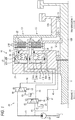
- a dual clutch device 10 includes a first wet-type clutch C1 and a second wet-type clutch C2.
- Reference numeral 11 denotes a clutch input shaft into which power of an engine E is transmitted.
- Reference numeral 12A denotes a first transmission input shaft on which a speed change gear train which establishes, for example, odd-numbered gears of a transmission T is provided, and reference numeral 12B denotes a second transmission input shaft on which a speed change gear train which establishes, for example, even-numbered gears is provided.
- the second input shaft 12B is supported rotatably via bearings 13 within a hollow shaft of the first input shaft 12A.
- the first wet-type clutch C1 includes a clutch hub 20 which rotates together with the clutch input shaft 11, a plurality of first inner plates 21A which are spline fitted in the clutch hub 20, a first clutch drum 22 which rotates together with the first transmission input shaft 12A, a plurality of first outer plates 21B which are disposed alternately between the first inner plates 21A and which are spline fitted in the first clutch drum 22 and a first cylindrical piston 23 which can press both the plates 21A, 21B together in an axial direction.
- the first piston 23 is accommodated slidably within a first annular piston chamber 24 which is defined within the clutch hub 20.
- a first hydraulic pressure chamber 25A and a first centrifugal hydraulic pressure canceling chamber 25B are defined by the first piston 23.
- Reference sign S denotes a seal member which seals up a gap between the first piston 23 and the first piston chamber 24.
- the first piston 23 moves one stroke in the axial direction to thereby bring the plates 21A, 21B into press contact with one another (the first wet-type clutch C1: applied).
- the first piston 23 is caused to move away from the plates 21A, 21B by means of a biasing force of the first return spring 26 and a hydraulic pressure force within the first centrifugal hydraulic pressure canceling chamber 25B to thereby release the plates 21A, 21B from the press contact state (the first wet-type clutch C1: released).
- the second wet-type clutch C2 includes a plurality of second outer plates 31A which are spline fitted in the clutch hub 20, a second clutch drum 32 which rotates together with the second transmission input shaft 12B, a plurality of second inner plates 31B which are disposed alternately between the second outer plates 31A and which are spline fitted in the second clutch drum 32, and a second cylindrical piston 33 which can press and contact both the plates 31A, 31B together in the axial direction.
- the second piston 33 is accommodated slidably within a second annular piston chamber 34 which is defined within the clutch hub 20.
- a second hydraulic pressure chamber 35A and a second centrifugal hydraulic pressure canceling chamber 35B are defined by the second piston 33.
- a second return spring 36 which is configured to bias the second piston 33 in a direction in which the second piston 33 moves away from the plates 31A, 31B, is accommodated within the second centrifugal hydraulic pressure canceling chamber 35B.
- Reference sign S denotes a seal member which seals up a gap between the second piston 33 and the second piston chamber 34.
- the second piston 33 moves one stroke in the axial direction to thereby bring the plates 31A, 31B into press contact with one another (the second wet-type clutch C2: applied).
- the second piston 33 is caused to move away from the plates 31A, 31B by means of a biasing force of the second return spring 36 and a hydraulic pressure within the second centrifugal hydrauli pressure canceling chamber 35B to thereby release the plates 31A, 31B from the press contact state (the second wet-type clutch C2: released).
- a hydraulic pressure circuit 40 has a first upstream supply line 43 which connects an oil pan 41 to a first solenoid valve 60 and a second upstream supply line 45 which branches off the first upstream supply line 43 to be connected to a second solenoid valve 65.
- An oil pump OP which is driven by the power of the engine E, is provided on a portion of the first upstream supply line 43 which lies upstream of the branch portion.
- a lubrication oil supply line 46 on which a throttle valve 47 is provided is connected to the second upstream supply line 45.
- a first downstream supply line 50 is connected to the first solenoid valve 60.
- This first downstream supply line 50 branches into a first hydraulic pressure chamber line 50A and a second canceling chamber line 50B within the clutch hub 20.
- a downstream end of the first hydraulic pressure chamber line 50A is connected to the first hydraulic pressure chamber 25A, and a downstream end of the second canceling chamber line 50B is connected to the second centrifugal hydraulic pressure canceling chamber 35B.
- the first solenoid valve 60 is closed by means of a biasing force of a spring 61 when it is deenergized (OFF) and is energized (ON) to be opened by an electronic control unit, not shown.
- a hydraulic pressure is supplied into the first hydraulic pressure chamber 25A and the second centrifugal hydraulic pressure canceling chamber 35B when the first solenoid valve 60 is opened (ON).
- the first solenoid valve 60 is closed (OFF)
- no hydraulic pressure is supplied into the first hydraulic pressure chamber 25A and the second centrifugal hydraulic pressure canceling chamber 35B
- the hydraulic pressures within the first hydraulic pressure chamber 25A and the second centrifugal hydraulic pressure canceling chamber 35B are returned to the oil pan 41 via a fluid return line 62.
- a second downstream supply line 51 is connected to a second solenoid valve 65.
- This second downstream supply line 51 branches into a second hydraulic pressure chamber line 51A and a first canceling chamber line 51B within the clutch hub 20.
- a downstream end of the second hydraulic pressure chamber line 51A is connected to the second hydraulic pressure chamber 35A, and a downstream end of the first canceling chamber line 51B is connected to the first centrifugal hydraulic pressure canceling chamber 25B.
- the second solenoid valve 65 is closed by means of a biasing force of a spring 66 when the second solenoid valve 65 is deenergized (OFF) and is energized (ON) to be opened by the electronic control unit.
- a hydraulic pressure is supplied into the second hydraulic pressure chamber 35A and the first centrifugal hydraulic pressure canceling chamber 25B.
- the second solenoid valve 65 is closed (OFF) when the second solenoid valve 65 is closed (OFF), no hydraulic pressure is supplied into the second hydraulic pressure chamber 35A and the first centrifugal hydraulic pressure canceling chamber 25B, and the hydraulic pressures in the second hydraulic pressure chamber 35A and the first centrifugal hydraulic pressure canceling chamber 25B are returned to the oil pan 41 via a fluid return line 67.
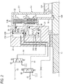
- the first wet-type clutch C1 When transmitting power from the clutch input shaft 11 to the first transmission input shaft 12A, as shown in Fig. 2 , the first wet-type clutch C1 is applied (the first solenoid valve 60: ON) and the second wet-type clutch C2 is released (the second solenoid valve 65: OFF).
- both the biasing force of the second return spring 36 and the hydraulic pressure within the second centrifugal hydraulic pressure canceling chamber 35B are applied to the second piston 33.
- the second piston 33 can be moved away from the plates 31A, 31B in an ensured manner, thereby making it possible to prevent a double meshing of the transmission in an ensured manner.
- the first wet-type clutch C1 is released (the first solenoid valve 60: OFF), and the second wet-type clutch C2 is applied (the second solenoid valve 65: ON).
- both the biasing force of the first return spring 26 and the hydraulic pressure within the first centrifugal hydraulic pressure canceling chamber 25B are applied to the first piston 23.
- the first piston 23 can be moved away from the plates 21A, 21B in an ensured manner, thereby making it possible to prevent a double meshing of the transmission in an ensured manner.
- R A1 denotes an outside diameter of the first piston 23, R B1 an outside diameter of the first centrifugal hydraulic pressure canceling chamber 25B, R A2 an outside diameter of the second piston 33, R B2 an outside diameter of the second centrifugal hydraulic pressure canceling chamber 35B, P a hydraulic pressure, F S1 a biasing force of the first return spring 26, and F S2 a biasing force of the second return spring 36.
Applications Claiming Priority (2)
| Application Number | Priority Date | Filing Date | Title |
|---|---|---|---|
| JP2014086378A JP6384099B2 (ja) | 2014-04-18 | 2014-04-18 | デュアルクラッチ装置 |
| PCT/JP2015/061733 WO2015159955A1 (fr) | 2014-04-18 | 2015-04-16 | Dispositif d'embrayage double |
Publications (3)
| Publication Number | Publication Date |
|---|---|
| EP3133310A1 true EP3133310A1 (fr) | 2017-02-22 |
| EP3133310A4 EP3133310A4 (fr) | 2018-01-03 |
| EP3133310B1 EP3133310B1 (fr) | 2019-10-23 |
Family
ID=54324156
Family Applications (1)
| Application Number | Title | Priority Date | Filing Date |
|---|---|---|---|
| EP15779222.7A Active EP3133310B1 (fr) | 2014-04-18 | 2015-04-16 | Dispositif d'embrayage double |
Country Status (5)
| Country | Link |
|---|---|
| US (1) | US10400835B2 (fr) |
| EP (1) | EP3133310B1 (fr) |
| JP (1) | JP6384099B2 (fr) |
| CN (1) | CN106795925B (fr) |
| WO (1) | WO2015159955A1 (fr) |
Cited By (1)
| Publication number | Priority date | Publication date | Assignee | Title |
|---|---|---|---|---|
| EP3232077A4 (fr) * | 2014-12-11 | 2018-08-29 | Isuzu Motors Limited | Dispositif d'embrayage double |
Families Citing this family (12)
| Publication number | Priority date | Publication date | Assignee | Title |
|---|---|---|---|---|
| JP6489039B2 (ja) | 2016-02-23 | 2019-03-27 | マツダ株式会社 | 自動変速機 |
| JP6330852B2 (ja) * | 2016-02-23 | 2018-05-30 | マツダ株式会社 | 自動変速機 |
| JP6315006B2 (ja) | 2016-02-23 | 2018-04-25 | マツダ株式会社 | 摩擦締結要素及び自動変速機 |
| US10767706B2 (en) | 2016-03-29 | 2020-09-08 | Mazda Motor Corporation | Automatic transmission and frictional engagement element |
| JP6369504B2 (ja) * | 2016-05-19 | 2018-08-08 | マツダ株式会社 | 自動変速機の制御方法及び制御装置 |
| JP6369502B2 (ja) * | 2016-05-19 | 2018-08-08 | マツダ株式会社 | 自動変速機の制御方法及び制御装置 |
| CN109937313B (zh) * | 2016-09-22 | 2021-03-26 | 莱纳玛公司 | 集成断开双离合器系统和双作用活塞 |
| RU2662337C1 (ru) * | 2017-07-05 | 2018-07-25 | Федеральное государственное унитарное предприятие "Центральный ордена Трудового Красного Знамени научно-исследовательский автомобильный и автомоторный институт "НАМИ" (ФГУП "НАМИ") | Двойное сцепление трансмиссии транспортного средства |
| FR3068746B1 (fr) * | 2017-07-06 | 2020-02-28 | Valeo Embrayages | Porte-disque de sortie d'un double embrayages et mecanisme comprenant un tel porte-disque |
| RU2670340C1 (ru) * | 2017-12-05 | 2018-10-22 | Федеральное государственное унитарное предприятие "Центральный ордена Трудового Красного Знамени научно-исследовательский автомобильный и автомоторный институт "НАМИ" (ФГУП "НАМИ") | Двойное сцепление для трансмиссий транспортных средств |
| RU2694426C1 (ru) * | 2018-05-07 | 2019-07-12 | Федеральное государственное унитарное предприятие "Центральный ордена Трудового Красного Знамени научно-исследовательский автомобильный и автомоторный институт "НАМИ" (ФГУП "НАМИ") | Двойная фрикционная муфта сцепления с гидравлическим управлением |
| RU2708963C1 (ru) * | 2019-03-04 | 2019-12-12 | Федеральное государственное унитарное предприятие "Центральный ордена Трудового Красного Знамени научно-исследовательский автомобильный и автомоторный институт "НАМИ" (ФГУП "НАМИ") | Двойная фрикционная муфта сцепления |
Family Cites Families (13)
| Publication number | Priority date | Publication date | Assignee | Title |
|---|---|---|---|---|
| JP2816768B2 (ja) * | 1990-12-17 | 1998-10-27 | アイシン・エィ・ダブリュ株式会社 | 自動変速機における油圧アクチュエータ装置 |
| DE19931973A1 (de) | 1999-07-09 | 2001-01-11 | Wabco Gmbh & Co Ohg | Einrichtung zum Steuern einer Stelleinrichtung für ein Getriebe |
| DE10121632A1 (de) | 2001-05-03 | 2002-11-07 | Zahnradfabrik Friedrichshafen | Schaltbares Getriebe |
| JP2004036807A (ja) * | 2002-07-05 | 2004-02-05 | Aisin Aw Co Ltd | 変速機の油圧制御装置 |
| DE102004034540B4 (de) | 2004-07-16 | 2013-07-25 | Zf Friedrichshafen Ag | Kupplungsanordnung mit einer Kühlkammer |
| DE102006054032A1 (de) | 2006-11-16 | 2008-05-21 | Zf Friedrichshafen Ag | Steuerungsvorrichtung für ein Getriebe und Verfahren zur Steuerung eines Getriebes |
| DE102007029634A1 (de) | 2007-06-26 | 2009-01-08 | Daimler Ag | Zahnräderwechselgetriebe |
| JP5455500B2 (ja) * | 2009-08-07 | 2014-03-26 | 株式会社エフ・シー・シー | 動力伝達装置 |
| JP5513199B2 (ja) * | 2010-03-26 | 2014-06-04 | 本田技研工業株式会社 | エンジンの油圧クラッチ用油路構造 |
| JP2013024331A (ja) * | 2011-07-21 | 2013-02-04 | Nsk Ltd | 無段変速装置 |
| EP2758687B1 (fr) * | 2011-09-23 | 2019-01-23 | Fca Us Llc | Appareil et procédé de remplissage automatique de l'embrayage d'une transmission pendant le fonctionnement d'un moteur en mode marche/arrêt |
| DE112012005428A5 (de) * | 2011-12-22 | 2014-09-25 | Schaeffler Technologies Gmbh & Co. Kg | Doppelkupplung |
| DE102014226150A1 (de) * | 2014-12-17 | 2016-06-23 | Zf Friedrichshafen Ag | Hydrauliksystem für ein Automatikgetriebe |
-
2014
- 2014-04-18 JP JP2014086378A patent/JP6384099B2/ja not_active Expired - Fee Related
-
2015
- 2015-04-16 EP EP15779222.7A patent/EP3133310B1/fr active Active
- 2015-04-16 CN CN201580020026.5A patent/CN106795925B/zh active Active
- 2015-04-16 WO PCT/JP2015/061733 patent/WO2015159955A1/fr active Application Filing
- 2015-04-16 US US15/304,832 patent/US10400835B2/en active Active
Cited By (2)
| Publication number | Priority date | Publication date | Assignee | Title |
|---|---|---|---|---|
| EP3232077A4 (fr) * | 2014-12-11 | 2018-08-29 | Isuzu Motors Limited | Dispositif d'embrayage double |
| US10274024B2 (en) | 2014-12-11 | 2019-04-30 | Isuzu Motors Limited | Dual clutch apparatus |
Also Published As
| Publication number | Publication date |
|---|---|
| CN106795925B (zh) | 2018-10-26 |
| US20170184160A1 (en) | 2017-06-29 |
| JP6384099B2 (ja) | 2018-09-05 |
| WO2015159955A1 (fr) | 2015-10-22 |
| US10400835B2 (en) | 2019-09-03 |
| EP3133310A4 (fr) | 2018-01-03 |
| JP2015206390A (ja) | 2015-11-19 |
| CN106795925A (zh) | 2017-05-31 |
| EP3133310B1 (fr) | 2019-10-23 |
Similar Documents
| Publication | Publication Date | Title |
|---|---|---|
| EP3133310B1 (fr) | Dispositif d'embrayage double | |
| US10040445B2 (en) | Drivetrain for a motor vehicle, and method for operating a drivetrain of said type | |
| KR101395744B1 (ko) | 이중 클러치 변속기용 유압 작동식 밸브 장치 | |
| EP3481660B1 (fr) | Dispositif de sortie secondaire | |
| WO2015067259A1 (fr) | Ensemble fluidique | |
| DE102008051458A1 (de) | Verteilergetriebe für einen Kraftfahrzeugantriebsstrang | |
| EP1657473A3 (fr) | Boîte de vitesse à double engrenage avec un dispositif de verrouillage d' action de synchronisation | |
| ITMI20010306A1 (it) | Dispositivo di trasmissione di momento torcente con almeno un primo dispositivo di frizione nonche' almeno un secondo dispositivo di frizion | |
| EP2820326B1 (fr) | Unité d'entraînement à plusieurs vitesses | |
| EP3232077B1 (fr) | Dispositif d'embrayage double | |
| WO2016019958A2 (fr) | Embrayage multidisque axial | |
| EP3719350A1 (fr) | Actionneur à double embrayage et ensemble d'entraînement comportant un tel actionneur | |
| DE112012000398B4 (de) | Hydraulisch betätigte Kupplung und mit derselbigen versehene Getriebevorrichtung | |
| EP3114363A2 (fr) | Dispositif de transmission de couple | |
| CN109372961B (zh) | 一种单控式三档变速器 | |
| DE102009010133A1 (de) | Zentralausrücker | |
| DE112008001057T5 (de) | Steuergerät eines Kupplungsmechanismus | |
| KR20140025147A (ko) | 더블클러치 변속기의 싱크 제어 방법 | |
| RU2556775C2 (ru) | Приводное устройство для автомобильной рабочей машины | |
| DE102009016002A1 (de) | Doppelkupplung und Doppelkupplungsgetriebe mit einer Parksperrenfunktion | |
| KR102487191B1 (ko) | 자동변속기용 동력전달장치 | |
| DE102016124014A1 (de) | Aktuatoranordnung für ein Kraftfahrzeuggetriebe | |
| DE102011005132A1 (de) | Anbindung einer als Lamellenbremse ausgeführten Wellenbremse an eine Getriebewelle eines Schiffsantriebs | |
| KR102186977B1 (ko) | 클러치 장치 | |
| RU105231U1 (ru) | Гидравлическое сцепление |
Legal Events
| Date | Code | Title | Description |
|---|---|---|---|
| STAA | Information on the status of an ep patent application or granted ep patent |
Free format text: STATUS: THE INTERNATIONAL PUBLICATION HAS BEEN MADE |
|
| PUAI | Public reference made under article 153(3) epc to a published international application that has entered the european phase |
Free format text: ORIGINAL CODE: 0009012 |
|
| STAA | Information on the status of an ep patent application or granted ep patent |
Free format text: STATUS: REQUEST FOR EXAMINATION WAS MADE |
|
| 17P | Request for examination filed |
Effective date: 20161118 |
|
| AK | Designated contracting states |
Kind code of ref document: A1 Designated state(s): AL AT BE BG CH CY CZ DE DK EE ES FI FR GB GR HR HU IE IS IT LI LT LU LV MC MK MT NL NO PL PT RO RS SE SI SK SM TR |
|
| AX | Request for extension of the european patent |
Extension state: BA ME |
|
| DAV | Request for validation of the european patent (deleted) | ||
| DAX | Request for extension of the european patent (deleted) | ||
| A4 | Supplementary search report drawn up and despatched |
Effective date: 20171204 |
|
| RIC1 | Information provided on ipc code assigned before grant |
Ipc: F16D 25/10 20060101AFI20171128BHEP Ipc: F16H 61/02 20060101ALI20171128BHEP |
|
| GRAP | Despatch of communication of intention to grant a patent |
Free format text: ORIGINAL CODE: EPIDOSNIGR1 |
|
| STAA | Information on the status of an ep patent application or granted ep patent |
Free format text: STATUS: GRANT OF PATENT IS INTENDED |
|
| INTG | Intention to grant announced |
Effective date: 20190626 |
|
| GRAS | Grant fee paid |
Free format text: ORIGINAL CODE: EPIDOSNIGR3 |
|
| GRAA | (expected) grant |
Free format text: ORIGINAL CODE: 0009210 |
|
| STAA | Information on the status of an ep patent application or granted ep patent |
Free format text: STATUS: THE PATENT HAS BEEN GRANTED |
|
| AK | Designated contracting states |
Kind code of ref document: B1 Designated state(s): AL AT BE BG CH CY CZ DE DK EE ES FI FR GB GR HR HU IE IS IT LI LT LU LV MC MK MT NL NO PL PT RO RS SE SI SK SM TR |
|
| REG | Reference to a national code |
Ref country code: GB Ref legal event code: FG4D |
|
| REG | Reference to a national code |
Ref country code: CH Ref legal event code: EP |
|
| REG | Reference to a national code |
Ref country code: IE Ref legal event code: FG4D |
|
| REG | Reference to a national code |
Ref country code: DE Ref legal event code: R096 Ref document number: 602015040356 Country of ref document: DE |
|
| REG | Reference to a national code |
Ref country code: AT Ref legal event code: REF Ref document number: 1193983 Country of ref document: AT Kind code of ref document: T Effective date: 20191115 |
|
| REG | Reference to a national code |
Ref country code: NL Ref legal event code: MP Effective date: 20191023 |
|
| REG | Reference to a national code |
Ref country code: LT Ref legal event code: MG4D |
|
| PG25 | Lapsed in a contracting state [announced via postgrant information from national office to epo] |
Ref country code: NL Free format text: LAPSE BECAUSE OF FAILURE TO SUBMIT A TRANSLATION OF THE DESCRIPTION OR TO PAY THE FEE WITHIN THE PRESCRIBED TIME-LIMIT Effective date: 20191023 Ref country code: GR Free format text: LAPSE BECAUSE OF FAILURE TO SUBMIT A TRANSLATION OF THE DESCRIPTION OR TO PAY THE FEE WITHIN THE PRESCRIBED TIME-LIMIT Effective date: 20200124 Ref country code: NO Free format text: LAPSE BECAUSE OF FAILURE TO SUBMIT A TRANSLATION OF THE DESCRIPTION OR TO PAY THE FEE WITHIN THE PRESCRIBED TIME-LIMIT Effective date: 20200123 Ref country code: BG Free format text: LAPSE BECAUSE OF FAILURE TO SUBMIT A TRANSLATION OF THE DESCRIPTION OR TO PAY THE FEE WITHIN THE PRESCRIBED TIME-LIMIT Effective date: 20200123 Ref country code: FI Free format text: LAPSE BECAUSE OF FAILURE TO SUBMIT A TRANSLATION OF THE DESCRIPTION OR TO PAY THE FEE WITHIN THE PRESCRIBED TIME-LIMIT Effective date: 20191023 Ref country code: PL Free format text: LAPSE BECAUSE OF FAILURE TO SUBMIT A TRANSLATION OF THE DESCRIPTION OR TO PAY THE FEE WITHIN THE PRESCRIBED TIME-LIMIT Effective date: 20191023 Ref country code: LT Free format text: LAPSE BECAUSE OF FAILURE TO SUBMIT A TRANSLATION OF THE DESCRIPTION OR TO PAY THE FEE WITHIN THE PRESCRIBED TIME-LIMIT Effective date: 20191023 Ref country code: PT Free format text: LAPSE BECAUSE OF FAILURE TO SUBMIT A TRANSLATION OF THE DESCRIPTION OR TO PAY THE FEE WITHIN THE PRESCRIBED TIME-LIMIT Effective date: 20200224 Ref country code: LV Free format text: LAPSE BECAUSE OF FAILURE TO SUBMIT A TRANSLATION OF THE DESCRIPTION OR TO PAY THE FEE WITHIN THE PRESCRIBED TIME-LIMIT Effective date: 20191023 Ref country code: SE Free format text: LAPSE BECAUSE OF FAILURE TO SUBMIT A TRANSLATION OF THE DESCRIPTION OR TO PAY THE FEE WITHIN THE PRESCRIBED TIME-LIMIT Effective date: 20191023 |
|
| PG25 | Lapsed in a contracting state [announced via postgrant information from national office to epo] |
Ref country code: HR Free format text: LAPSE BECAUSE OF FAILURE TO SUBMIT A TRANSLATION OF THE DESCRIPTION OR TO PAY THE FEE WITHIN THE PRESCRIBED TIME-LIMIT Effective date: 20191023 Ref country code: RS Free format text: LAPSE BECAUSE OF FAILURE TO SUBMIT A TRANSLATION OF THE DESCRIPTION OR TO PAY THE FEE WITHIN THE PRESCRIBED TIME-LIMIT Effective date: 20191023 Ref country code: IS Free format text: LAPSE BECAUSE OF FAILURE TO SUBMIT A TRANSLATION OF THE DESCRIPTION OR TO PAY THE FEE WITHIN THE PRESCRIBED TIME-LIMIT Effective date: 20200224 |
|
| PG25 | Lapsed in a contracting state [announced via postgrant information from national office to epo] |
Ref country code: AL Free format text: LAPSE BECAUSE OF FAILURE TO SUBMIT A TRANSLATION OF THE DESCRIPTION OR TO PAY THE FEE WITHIN THE PRESCRIBED TIME-LIMIT Effective date: 20191023 |
|
| REG | Reference to a national code |
Ref country code: DE Ref legal event code: R097 Ref document number: 602015040356 Country of ref document: DE |
|
| PG2D | Information on lapse in contracting state deleted |
Ref country code: IS |
|
| PG25 | Lapsed in a contracting state [announced via postgrant information from national office to epo] |
Ref country code: ES Free format text: LAPSE BECAUSE OF FAILURE TO SUBMIT A TRANSLATION OF THE DESCRIPTION OR TO PAY THE FEE WITHIN THE PRESCRIBED TIME-LIMIT Effective date: 20191023 Ref country code: CZ Free format text: LAPSE BECAUSE OF FAILURE TO SUBMIT A TRANSLATION OF THE DESCRIPTION OR TO PAY THE FEE WITHIN THE PRESCRIBED TIME-LIMIT Effective date: 20191023 Ref country code: DK Free format text: LAPSE BECAUSE OF FAILURE TO SUBMIT A TRANSLATION OF THE DESCRIPTION OR TO PAY THE FEE WITHIN THE PRESCRIBED TIME-LIMIT Effective date: 20191023 Ref country code: EE Free format text: LAPSE BECAUSE OF FAILURE TO SUBMIT A TRANSLATION OF THE DESCRIPTION OR TO PAY THE FEE WITHIN THE PRESCRIBED TIME-LIMIT Effective date: 20191023 Ref country code: RO Free format text: LAPSE BECAUSE OF FAILURE TO SUBMIT A TRANSLATION OF THE DESCRIPTION OR TO PAY THE FEE WITHIN THE PRESCRIBED TIME-LIMIT Effective date: 20191023 Ref country code: IS Free format text: LAPSE BECAUSE OF FAILURE TO SUBMIT A TRANSLATION OF THE DESCRIPTION OR TO PAY THE FEE WITHIN THE PRESCRIBED TIME-LIMIT Effective date: 20200223 |
|
| REG | Reference to a national code |
Ref country code: AT Ref legal event code: MK05 Ref document number: 1193983 Country of ref document: AT Kind code of ref document: T Effective date: 20191023 |
|
| PLBE | No opposition filed within time limit |
Free format text: ORIGINAL CODE: 0009261 |
|
| STAA | Information on the status of an ep patent application or granted ep patent |
Free format text: STATUS: NO OPPOSITION FILED WITHIN TIME LIMIT |
|
| PG25 | Lapsed in a contracting state [announced via postgrant information from national office to epo] |
Ref country code: IT Free format text: LAPSE BECAUSE OF FAILURE TO SUBMIT A TRANSLATION OF THE DESCRIPTION OR TO PAY THE FEE WITHIN THE PRESCRIBED TIME-LIMIT Effective date: 20191023 Ref country code: SM Free format text: LAPSE BECAUSE OF FAILURE TO SUBMIT A TRANSLATION OF THE DESCRIPTION OR TO PAY THE FEE WITHIN THE PRESCRIBED TIME-LIMIT Effective date: 20191023 Ref country code: SK Free format text: LAPSE BECAUSE OF FAILURE TO SUBMIT A TRANSLATION OF THE DESCRIPTION OR TO PAY THE FEE WITHIN THE PRESCRIBED TIME-LIMIT Effective date: 20191023 |
|
| 26N | No opposition filed |
Effective date: 20200724 |
|
| PG25 | Lapsed in a contracting state [announced via postgrant information from national office to epo] |
Ref country code: AT Free format text: LAPSE BECAUSE OF FAILURE TO SUBMIT A TRANSLATION OF THE DESCRIPTION OR TO PAY THE FEE WITHIN THE PRESCRIBED TIME-LIMIT Effective date: 20191023 Ref country code: MC Free format text: LAPSE BECAUSE OF FAILURE TO SUBMIT A TRANSLATION OF THE DESCRIPTION OR TO PAY THE FEE WITHIN THE PRESCRIBED TIME-LIMIT Effective date: 20191023 Ref country code: SI Free format text: LAPSE BECAUSE OF FAILURE TO SUBMIT A TRANSLATION OF THE DESCRIPTION OR TO PAY THE FEE WITHIN THE PRESCRIBED TIME-LIMIT Effective date: 20191023 |
|
| REG | Reference to a national code |
Ref country code: CH Ref legal event code: PL |
|
| PG25 | Lapsed in a contracting state [announced via postgrant information from national office to epo] |
Ref country code: LU Free format text: LAPSE BECAUSE OF NON-PAYMENT OF DUE FEES Effective date: 20200416 Ref country code: CH Free format text: LAPSE BECAUSE OF NON-PAYMENT OF DUE FEES Effective date: 20200430 Ref country code: LI Free format text: LAPSE BECAUSE OF NON-PAYMENT OF DUE FEES Effective date: 20200430 |
|
| REG | Reference to a national code |
Ref country code: BE Ref legal event code: MM Effective date: 20200430 |
|
| PG25 | Lapsed in a contracting state [announced via postgrant information from national office to epo] |
Ref country code: BE Free format text: LAPSE BECAUSE OF NON-PAYMENT OF DUE FEES Effective date: 20200430 |
|
| PG25 | Lapsed in a contracting state [announced via postgrant information from national office to epo] |
Ref country code: IE Free format text: LAPSE BECAUSE OF NON-PAYMENT OF DUE FEES Effective date: 20200416 |
|
| PG25 | Lapsed in a contracting state [announced via postgrant information from national office to epo] |
Ref country code: TR Free format text: LAPSE BECAUSE OF FAILURE TO SUBMIT A TRANSLATION OF THE DESCRIPTION OR TO PAY THE FEE WITHIN THE PRESCRIBED TIME-LIMIT Effective date: 20191023 Ref country code: MT Free format text: LAPSE BECAUSE OF FAILURE TO SUBMIT A TRANSLATION OF THE DESCRIPTION OR TO PAY THE FEE WITHIN THE PRESCRIBED TIME-LIMIT Effective date: 20191023 Ref country code: CY Free format text: LAPSE BECAUSE OF FAILURE TO SUBMIT A TRANSLATION OF THE DESCRIPTION OR TO PAY THE FEE WITHIN THE PRESCRIBED TIME-LIMIT Effective date: 20191023 |
|
| PG25 | Lapsed in a contracting state [announced via postgrant information from national office to epo] |
Ref country code: MK Free format text: LAPSE BECAUSE OF FAILURE TO SUBMIT A TRANSLATION OF THE DESCRIPTION OR TO PAY THE FEE WITHIN THE PRESCRIBED TIME-LIMIT Effective date: 20191023 |
|
| PGFP | Annual fee paid to national office [announced via postgrant information from national office to epo] |
Ref country code: FR Payment date: 20230309 Year of fee payment: 9 |
|
| PGFP | Annual fee paid to national office [announced via postgrant information from national office to epo] |
Ref country code: GB Payment date: 20230302 Year of fee payment: 9 |
|
| PGFP | Annual fee paid to national office [announced via postgrant information from national office to epo] |
Ref country code: DE Payment date: 20230228 Year of fee payment: 9 |