EP3133186A2 - Ultraviolette photodetektoren und verfahren zur herstellung von ultravioletten photodetektoren - Google Patents
Ultraviolette photodetektoren und verfahren zur herstellung von ultravioletten photodetektoren Download PDFInfo
- Publication number
- EP3133186A2 EP3133186A2 EP16181398.5A EP16181398A EP3133186A2 EP 3133186 A2 EP3133186 A2 EP 3133186A2 EP 16181398 A EP16181398 A EP 16181398A EP 3133186 A2 EP3133186 A2 EP 3133186A2
- Authority
- EP
- European Patent Office
- Prior art keywords
- metal
- oxide film
- coat
- containing oxide
- zinc
- Prior art date
- Legal status (The legal status is an assumption and is not a legal conclusion. Google has not performed a legal analysis and makes no representation as to the accuracy of the status listed.)
- Granted
Links
Images



Classifications
-
- H—ELECTRICITY
- H10—SEMICONDUCTOR DEVICES; ELECTRIC SOLID-STATE DEVICES NOT OTHERWISE PROVIDED FOR
- H10F—INORGANIC SEMICONDUCTOR DEVICES SENSITIVE TO INFRARED RADIATION, LIGHT, ELECTROMAGNETIC RADIATION OF SHORTER WAVELENGTH OR CORPUSCULAR RADIATION
- H10F71/00—Manufacture or treatment of devices covered by this subclass
- H10F71/125—The active layers comprising only Group II-VI materials, e.g. CdS, ZnS or CdTe
- H10F71/1253—The active layers comprising only Group II-VI materials, e.g. CdS, ZnS or CdTe comprising at least three elements, e.g. HgCdTe
-
- C—CHEMISTRY; METALLURGY
- C01—INORGANIC CHEMISTRY
- C01G—COMPOUNDS CONTAINING METALS NOT COVERED BY SUBCLASSES C01D OR C01F
- C01G9/00—Compounds of zinc
- C01G9/006—Compounds containing zinc, with or without oxygen or hydrogen, and containing two or more other elements
-
- C—CHEMISTRY; METALLURGY
- C09—DYES; PAINTS; POLISHES; NATURAL RESINS; ADHESIVES; COMPOSITIONS NOT OTHERWISE PROVIDED FOR; APPLICATIONS OF MATERIALS NOT OTHERWISE PROVIDED FOR
- C09D—COATING COMPOSITIONS, e.g. PAINTS, VARNISHES OR LACQUERS; FILLING PASTES; CHEMICAL PAINT OR INK REMOVERS; INKS; CORRECTING FLUIDS; WOODSTAINS; PASTES OR SOLIDS FOR COLOURING OR PRINTING; USE OF MATERIALS THEREFOR
- C09D1/00—Coating compositions, e.g. paints, varnishes or lacquers, based on inorganic substances
-
- C—CHEMISTRY; METALLURGY
- C09—DYES; PAINTS; POLISHES; NATURAL RESINS; ADHESIVES; COMPOSITIONS NOT OTHERWISE PROVIDED FOR; APPLICATIONS OF MATERIALS NOT OTHERWISE PROVIDED FOR
- C09D—COATING COMPOSITIONS, e.g. PAINTS, VARNISHES OR LACQUERS; FILLING PASTES; CHEMICAL PAINT OR INK REMOVERS; INKS; CORRECTING FLUIDS; WOODSTAINS; PASTES OR SOLIDS FOR COLOURING OR PRINTING; USE OF MATERIALS THEREFOR
- C09D5/00—Coating compositions, e.g. paints, varnishes or lacquers, characterised by their physical nature or the effects produced; Filling pastes
- C09D5/24—Electrically-conducting paints
-
- C—CHEMISTRY; METALLURGY
- C09—DYES; PAINTS; POLISHES; NATURAL RESINS; ADHESIVES; COMPOSITIONS NOT OTHERWISE PROVIDED FOR; APPLICATIONS OF MATERIALS NOT OTHERWISE PROVIDED FOR
- C09D—COATING COMPOSITIONS, e.g. PAINTS, VARNISHES OR LACQUERS; FILLING PASTES; CHEMICAL PAINT OR INK REMOVERS; INKS; CORRECTING FLUIDS; WOODSTAINS; PASTES OR SOLIDS FOR COLOURING OR PRINTING; USE OF MATERIALS THEREFOR
- C09D5/00—Coating compositions, e.g. paints, varnishes or lacquers, characterised by their physical nature or the effects produced; Filling pastes
- C09D5/32—Radiation-absorbing paints
-
- C—CHEMISTRY; METALLURGY
- C23—COATING METALLIC MATERIAL; COATING MATERIAL WITH METALLIC MATERIAL; CHEMICAL SURFACE TREATMENT; DIFFUSION TREATMENT OF METALLIC MATERIAL; COATING BY VACUUM EVAPORATION, BY SPUTTERING, BY ION IMPLANTATION OR BY CHEMICAL VAPOUR DEPOSITION, IN GENERAL; INHIBITING CORROSION OF METALLIC MATERIAL OR INCRUSTATION IN GENERAL
- C23C—COATING METALLIC MATERIAL; COATING MATERIAL WITH METALLIC MATERIAL; SURFACE TREATMENT OF METALLIC MATERIAL BY DIFFUSION INTO THE SURFACE, BY CHEMICAL CONVERSION OR SUBSTITUTION; COATING BY VACUUM EVAPORATION, BY SPUTTERING, BY ION IMPLANTATION OR BY CHEMICAL VAPOUR DEPOSITION, IN GENERAL
- C23C18/00—Chemical coating by decomposition of either liquid compounds or solutions of the coating forming compounds, without leaving reaction products of surface material in the coating; Contact plating
- C23C18/02—Chemical coating by decomposition of either liquid compounds or solutions of the coating forming compounds, without leaving reaction products of surface material in the coating; Contact plating by thermal decomposition
- C23C18/12—Chemical coating by decomposition of either liquid compounds or solutions of the coating forming compounds, without leaving reaction products of surface material in the coating; Contact plating by thermal decomposition characterised by the deposition of inorganic material other than metallic material
- C23C18/1204—Chemical coating by decomposition of either liquid compounds or solutions of the coating forming compounds, without leaving reaction products of surface material in the coating; Contact plating by thermal decomposition characterised by the deposition of inorganic material other than metallic material inorganic material, e.g. non-oxide and non-metallic such as sulfides, nitrides based compounds
- C23C18/1208—Oxides, e.g. ceramics
- C23C18/1216—Metal oxides
-
- C—CHEMISTRY; METALLURGY
- C23—COATING METALLIC MATERIAL; COATING MATERIAL WITH METALLIC MATERIAL; CHEMICAL SURFACE TREATMENT; DIFFUSION TREATMENT OF METALLIC MATERIAL; COATING BY VACUUM EVAPORATION, BY SPUTTERING, BY ION IMPLANTATION OR BY CHEMICAL VAPOUR DEPOSITION, IN GENERAL; INHIBITING CORROSION OF METALLIC MATERIAL OR INCRUSTATION IN GENERAL
- C23C—COATING METALLIC MATERIAL; COATING MATERIAL WITH METALLIC MATERIAL; SURFACE TREATMENT OF METALLIC MATERIAL BY DIFFUSION INTO THE SURFACE, BY CHEMICAL CONVERSION OR SUBSTITUTION; COATING BY VACUUM EVAPORATION, BY SPUTTERING, BY ION IMPLANTATION OR BY CHEMICAL VAPOUR DEPOSITION, IN GENERAL
- C23C18/00—Chemical coating by decomposition of either liquid compounds or solutions of the coating forming compounds, without leaving reaction products of surface material in the coating; Contact plating
- C23C18/02—Chemical coating by decomposition of either liquid compounds or solutions of the coating forming compounds, without leaving reaction products of surface material in the coating; Contact plating by thermal decomposition
- C23C18/12—Chemical coating by decomposition of either liquid compounds or solutions of the coating forming compounds, without leaving reaction products of surface material in the coating; Contact plating by thermal decomposition characterised by the deposition of inorganic material other than metallic material
- C23C18/1225—Deposition of multilayers of inorganic material
-
- C—CHEMISTRY; METALLURGY
- C23—COATING METALLIC MATERIAL; COATING MATERIAL WITH METALLIC MATERIAL; CHEMICAL SURFACE TREATMENT; DIFFUSION TREATMENT OF METALLIC MATERIAL; COATING BY VACUUM EVAPORATION, BY SPUTTERING, BY ION IMPLANTATION OR BY CHEMICAL VAPOUR DEPOSITION, IN GENERAL; INHIBITING CORROSION OF METALLIC MATERIAL OR INCRUSTATION IN GENERAL
- C23C—COATING METALLIC MATERIAL; COATING MATERIAL WITH METALLIC MATERIAL; SURFACE TREATMENT OF METALLIC MATERIAL BY DIFFUSION INTO THE SURFACE, BY CHEMICAL CONVERSION OR SUBSTITUTION; COATING BY VACUUM EVAPORATION, BY SPUTTERING, BY ION IMPLANTATION OR BY CHEMICAL VAPOUR DEPOSITION, IN GENERAL
- C23C18/00—Chemical coating by decomposition of either liquid compounds or solutions of the coating forming compounds, without leaving reaction products of surface material in the coating; Contact plating
- C23C18/02—Chemical coating by decomposition of either liquid compounds or solutions of the coating forming compounds, without leaving reaction products of surface material in the coating; Contact plating by thermal decomposition
- C23C18/12—Chemical coating by decomposition of either liquid compounds or solutions of the coating forming compounds, without leaving reaction products of surface material in the coating; Contact plating by thermal decomposition characterised by the deposition of inorganic material other than metallic material
- C23C18/125—Process of deposition of the inorganic material
- C23C18/1275—Process of deposition of the inorganic material performed under inert atmosphere
-
- C—CHEMISTRY; METALLURGY
- C23—COATING METALLIC MATERIAL; COATING MATERIAL WITH METALLIC MATERIAL; CHEMICAL SURFACE TREATMENT; DIFFUSION TREATMENT OF METALLIC MATERIAL; COATING BY VACUUM EVAPORATION, BY SPUTTERING, BY ION IMPLANTATION OR BY CHEMICAL VAPOUR DEPOSITION, IN GENERAL; INHIBITING CORROSION OF METALLIC MATERIAL OR INCRUSTATION IN GENERAL
- C23C—COATING METALLIC MATERIAL; COATING MATERIAL WITH METALLIC MATERIAL; SURFACE TREATMENT OF METALLIC MATERIAL BY DIFFUSION INTO THE SURFACE, BY CHEMICAL CONVERSION OR SUBSTITUTION; COATING BY VACUUM EVAPORATION, BY SPUTTERING, BY ION IMPLANTATION OR BY CHEMICAL VAPOUR DEPOSITION, IN GENERAL
- C23C18/00—Chemical coating by decomposition of either liquid compounds or solutions of the coating forming compounds, without leaving reaction products of surface material in the coating; Contact plating
- C23C18/02—Chemical coating by decomposition of either liquid compounds or solutions of the coating forming compounds, without leaving reaction products of surface material in the coating; Contact plating by thermal decomposition
- C23C18/12—Chemical coating by decomposition of either liquid compounds or solutions of the coating forming compounds, without leaving reaction products of surface material in the coating; Contact plating by thermal decomposition characterised by the deposition of inorganic material other than metallic material
- C23C18/125—Process of deposition of the inorganic material
- C23C18/1279—Process of deposition of the inorganic material performed under reactive atmosphere, e.g. oxidising or reducing atmospheres
-
- H—ELECTRICITY
- H10—SEMICONDUCTOR DEVICES; ELECTRIC SOLID-STATE DEVICES NOT OTHERWISE PROVIDED FOR
- H10F—INORGANIC SEMICONDUCTOR DEVICES SENSITIVE TO INFRARED RADIATION, LIGHT, ELECTROMAGNETIC RADIATION OF SHORTER WAVELENGTH OR CORPUSCULAR RADIATION
- H10F71/00—Manufacture or treatment of devices covered by this subclass
- H10F71/128—Annealing
-
- G—PHYSICS
- G01—MEASURING; TESTING
- G01J—MEASUREMENT OF INTENSITY, VELOCITY, SPECTRAL CONTENT, POLARISATION, PHASE OR PULSE CHARACTERISTICS OF INFRARED, VISIBLE OR ULTRAVIOLET LIGHT; COLORIMETRY; RADIATION PYROMETRY
- G01J1/00—Photometry, e.g. photographic exposure meter
- G01J1/42—Photometry, e.g. photographic exposure meter using electric radiation detectors
- G01J1/429—Photometry, e.g. photographic exposure meter using electric radiation detectors applied to measurement of ultraviolet light
Definitions
- the present disclosure relates to photodetectors, and more particularly to ultraviolet (UV) photodetectors and methods of making UV photodetectors.
- UV ultraviolet
- UV photodetectors are commonly used in environmental monitoring applications to detect the appearance of a UV radiation source, such as flames and fire. Since UV radiation from flames and fire can reach a UV photodetector more quickly than other indicators of flame or fire may reach other types of detectors, UV photodetectors can provide indication of the appearance of the flame and fire in a monitored environment more rapidly than other types of detectors. UV photodetectors can include UV-sensitive film. The UV-sensitive film may have a large band gap, are solar blind, are stable, and are highly responsive to changes in the amount UV radiation present in a monitored environment. Semiconducting thin films are generally deposited using chemical vapor deposition (CVD), molecular beam epitaxy (MBE), or sputtering techniques. CVD, MBE, or sputtering techniques can render semiconducting thin films prohibitively expensive for applications like flame detectors because of the expense associated with the equipment typically required for depositing semiconducting thin films.
- CVD chemical vapor deposition
- MBE molecular beam epitaxy
- UV photodetectors and methods of making UV photodetectors have generally been considered satisfactory for their intended purpose.
- UV photodetectors and methods of making UV photodetectors there is still a need in the art for improved UV photodetectors and methods of making UV photodetectors.
- the present disclosure provides a solution for this need.
- a method of making an ultraviolet (UV) photodetector includes applying a metal-containing solution to a substrate using a chemical solution deposition (CSD) technique to form a metal-containing coat.
- the metal-containing coat is baked to drive solvent from the metal-containing coat.
- the metal-containing coat is then pyrolyzed to form a metal-containing oxide film with a cubic crystalline structure throughout suitable for ultraviolet photodetectors in flame detection applications.
- the metal-containing oxide film includes magnesium and zinc in a ratio that corresponds to a ratio of magnesium to zinc in organometallic starting compounds included in the metal-containing solution.
- pyrolyzing the metal-containing solution coat can include developing a metal-containing oxide film with a polycrystalline structure.
- the polycrystalline structure can include an amorphous crystalline structure, a cubic crystalline structure, or both amorphous and cubic crystalline structures.
- Pyrolyzing the metal-containing coat can include forming the metal-containing film without oxidizing or volatizing organic ligands present within the metal-containing coat.
- Pyrolyzing the metal-containing coat can include flowing an inert gas over the metal-containing coat while the metal-containing oxide layer is pyrolyzed.
- the inert gas can include argon, nitrogen, or any other suitable inert gas.
- Pyrolyzing the metal-containing coat can include placing the metal-containing coat in a furnace for a predetermined pyrolyzing time interval after the furnace has been preheated to a predetermined pyrolyzing temperature.
- the pyrolyzing time interval can be between five (5) and thirty minutes.
- the pyrolyzing temperature can be between about 450 and 550 degrees Celsius.
- the metal-containing oxide film can be quenched after undergoing pyrolysis.
- the method can include calcining the metal-containing oxide film. Calcining can be done in an oxygen rich atmosphere, such as an atmosphere containing 20% or more oxygen mixed with an inert gas. Calcining the metal-containing oxide film can include removing interstitial zinc, such as by oxidizing the interstitial zinc disposed within the lattice of the metal-containing oxide film. Calcining the metal-containing oxide film can include placing the metal-containing oxide film in a furnace for a predetermined calcining interval after the furnace has been preheated to a predetermined calcining temperature. The calcining time interval can be between about ten (10) and thirty (30) minutes. The calcining temperature can be between about 650 and 750 degrees Celsius. It is also contemplated that calcining the metal-containing oxide film can include fully developing a cubic crystalline structure throughout the metal-containing oxide film such that substantially no hexagonal (wurtzite) crystalline structure is present in the metal-containing oxide layer.
- the method can include annealing the metal-containing oxide layer.
- the annealing can include a low-temperature anneal and can be done subsequent to calcining the metal-containing oxide film to form the metal-containing oxide layer.
- the low-temperature anneal can develop a cubic crystalline microstructure within the metal-containing oxide layer, such as by fully developing a cubic crystalline microstructure throughout the metal-containing oxide layer by removing or converting a non-cubic portion of the crystalline structure remaining in the metal-containing oxide layer subsequent to calcining.
- the metal-containing oxide layer can be quenched after undergoing calcining.
- the CSD technique can include applying the metal-containing solution to the substrate using a spin coat technique, a dip coat technique, an aerosol coat technique, or any other suitable CSD technique.
- the spin coat technique can include flooding the substrate with the metal-containing solution and then spinning the flooded substrate and metal-containing solution at a predetermined coat speed for a predetermined coat interval.
- the flooded substrate is spun at about 1,500 rotations per minute for thirty (30) seconds to develop a metal-containing coat that, after pyrolyzing and calcining, has a thickness of between about twenty-five (25) and about fifty (50) nanometers.
- the metal-containing coat can be gently baked subsequent to spin coating. Baking the metal-containing coat can be done prior to pyrolyzing the metal-containing coat.
- the metal-containing coat can be baked at a predetermined bake temperature that is less than the predetermined pyrolyzing temperature. Baking the metal-containing coat can include driving the solvent out of the metal-containing coat. Baking the metal-containing coat can include, for example, placing the metal-containing coat on a hot plate for a predetermined temperature for a predetermined time interval.
- the method can include developing a film stack with a plurality of metal-containing oxide films on the substrate prior to calcining the film stack. For example, subsequent to applying a first metal-containing solution to form a first metal-containing coat and pyrolyzing the first metal-containing coat to form a first metal-containing oxide film, a second metal-containing solution can be applied to form a second metal-containing coat. The second metal-containing coat can be pyrolyzed to form a second metal-containing film, and both the first and second metal-containing films can be calcined to form a compositionally uniform layer stack including first and second metal-containing oxide layers.
- Electrodes can be coupled to the substrate and electrically connected to the metal-containing oxide layers.
- a pair of electrodes can be coupled to the substrate prior to applying the first metal-containing coat to the substrate.
- the pair of electrodes can be coupled to the substrate by the first metal-containing oxide layer, such as by coupling the electrodes to the metal-containing oxide film subsequent to pyrolyzing the first metal-containing oxide coat.
- the pair of electrodes can be coupled to the substrate by both the first and second metal-containing oxide layers, such as by coupling the electrodes to the second metal-containing oxide film subsequent to pyrolysis or after calcining the first and second metal-containing metal oxide films. Coupling the electrodes can include developing the electrodes using a deposition technique.
- the metal-containing solution can include both magnesium and zinc starting compounds.
- the metal-containing solution can include a zinc source, like zinc 2-ethylhexanoate.
- the metal-containing solution can include a magnesium source, like magnesium 2-ethylhexanoate.
- the metal-containing solution can include a solvent, like toluene.
- the metal-containing solution can include a stabilizer.
- the stabilizer can include a tri-functional chemical solution deposition additive with an amino alcohol.
- the amino alcohol can include one or more hydroxyl groups and one or more amines.
- the amino alcohol can include a primary amine, a primary amine and a secondary amine, or primary, secondary, and tertiary amines.
- the amino alcohol may include monoethanolamine, diethanolamine, triethanolamine, hetpaminol, isoetarine, noepinephrine, propanolamine, shphingosine, or methanolamine.
- a method of stabilizing an organometallic precursor in a chemical solution deposition reaction includes adding a tri-functional chemical solution deposition additive to a metal-containing solution having a organometallic precursor prior to application of the metal-containing solution to a substrate.
- the organometallic precursor can be a metal 2-ethylhexanoate, such as magnesium 2-ethylhexanoate or zinc 2-ethylhexanoate.
- the tri-functional chemical solution deposition additive can be diethanolamine.
- the tri-functional chemical solution deposition additive can be added to the organometallic precursor in a ratio of between about 0.05 to 1 and about 1 to 1 of additive: total weight of all metals in the metal-containing solution.
- the tri-functional chemical solution deposition additive can be added to the organometallic precursor in a 1 to 1 ratio.
- a method for stabilizing an organometallic precursor in a chemical solution deposition reaction comprises adding a tri-functional chemical solution deposition additive to a solution of organometallic precursor prior to deposition.
- the organometallic precursor can be a metal 2-ethylhexanoate.
- the metal 2-ethylhexanoate can be magnesium 2-ethylhexanoate or zinc 2-ethylhexanoate.
- the tri-functional chemical solution deposition can be an additive diethanolamine.
- the tri-functional chemical solution deposition additive can be added to the organometallic precursor in a ratio of between 0.05 to 1 and 1 to 1 of additive to total weight of all metals in the solution. Tri-functional chemical solution deposition additive can be added to the organometallic precursor in a 1 to 1 ratio.
- a method of increasing crystal growth in a chemical solution deposition reaction includes adding a tri-functional chemical solution deposition additive to the organometallic precursor prior to deposition.
- the tri-functional chemical solution deposition additive can be diethanolamine.
- the crystal can have a composition according to Mg x Zn (1-x)O , x being between about 0.5 and about 0.8.
- FIG. 1 an exemplary embodiment of a an ultraviolet (UV) photodetector in accordance with the disclosure is shown in Fig. 1 , and is designated generally by reference character 100.
- the systems and methods described herein can be used in fire and flame detection devices, such as in residential settings.
- UV photodetector 100 generally includes a substrate 10, a layer stack 50 having a plurality of layers, and one or more electrodes 30.
- Substrate 10 structurally supports layer stack 50 and the one or more electrodes 30, and may include silicon or any other suitable structure.
- Layer stack 50 overlays substrate 10, and in the illustrated exemplary embodiment includes seven layers overlaying one another. In this respect a first layer 16 overlays substrate 10, a second layer 18 overlays first layer 16, a third layer 20 overlays second layer 18, a fourth layer 22 overlays third layer 20, a fifth layer 24 overlays fourth layer 22, a sixth layer 26 overlays fifth layer 24, and a seventh (or incident) layer 28 overlays sixth layer 26.
- UV photodetector may have one, two, or any number of layers as suitable for a given application.
- the one or more electrodes 30 are coupled to substrate 10 through film stack 50, and are electrically connected to film stack 50.
- UV photodetector 100 is configured to selectively redirect incident UV radiation to a photodetector 36 that determines whether flame is present via state circuitry and/or software (not shown for reasons of clarity).
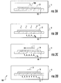
- method 100 includes applying a metal-containing solution 200 to a substrate 10 using a spin coater 2. The applied metal-containing solution forms a metal-containing coat 12 overlaying substrate 10. As indicated at B, metal-containing coat 12 is then gently baked to drive out solvent S from metal-containing coat 12. As indicated at C, metal-containing coat 12 (shown in A) is pyrolyzed using a pyrolyzing furnace 4 to form a metal-containing film 14 with a polycrystalline structure having a cubic phase i and an amorphous phase ii. As indicated at D, the metal-containing film 14 (shown in B) is then calcined using a calcining furnace 6, thereby forming a metal-containing-layer 16 with a cubic crystalline structure I throughout.
- Metal-containing solution 200 includes an organometallic precursor, such as a metal ion ligated or chelated by an organic moiety.
- metal-containing solution 200 includes one or more organometallic precursors with both magnesium and zinc in a predetermined ratio.
- Metal-containing film 14 includes a magnesium and zinc in a ratio corresponding to the predetermined ratio metal-containing solution 200.
- Metal-containing oxide layer 16 includes magnesium and zinc in a ratio corresponding to metal-containing film 14. The ratio of magnesium to zinc in the metal-containing solution, metal-containing film, and metal-containing oxide layer generally corresponds to Mg x Zn (1-x) O.
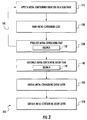
- method 100 includes applying a metal-containing solution to a substrate, e.g. metal-containing solution 200 and substrate 10 (both shown in Fig. 2 ), using a chemical solution deposition (CSD) technique.
- a metal-containing solution to a substrate
- metal-containing solution 200 and substrate 10 both shown in Fig. 2
- CSD chemical solution deposition
- Metal-containing coat 12 can be gently baked, i.e. at a temperature that is lower than the pyrolyzing temperature, as shown with box 120, to drive solvent out of the metal-containing coat (also shown in Fig. 2B ).
- the metal-containing coat is thereafter pyrolyzed, as shown in box 130, to form a metal-containing oxide film, e.g.
- metal-containing oxide film layer 14 (shown in Fig. 2C ), to form a polycrystalline structure having both amorphous and cubic crystal microstructure therein.
- the metal-containing film may be quenched subsequent to pyrolysis.
- the metal-containing oxide film can be then calcined to form a metal-containing oxide layer with a cubic crystalline structure, e.g. metal-containing oxide layer 16 (shown in Fig. 2D ).
- the metal-containing layer may be quenched subsequent to calcining.
- Method 100 can include developing a film stack on the substrate by successively applying the metal-containing solution to the underlying metal-containing oxide film to form an overlying metal-containing coat, and pyrolyzing the overlying metal-containing coat to form an overlying metal-containing oxide film, as indicated by arrow 160.
- a second metal-containing coat can be applied over the first metal-containing oxide film.
- the second metal-containing coat can be pyrolyzed, thereby forming a film stack comprising first and second metal-containing oxide films overlaying the substrate.
- the film stacks can thereafter be calcined to form a layer stack, e.g. layer stack 50 (shown in Fig. 1 ), overlaying the substrate.
- both the first and second metal-containing oxide films include magnesium-zinc oxide films.
- Gently baking the metal-containing solution coating 120 can be done immediately after applying the metal-containing solution coating 12 (shown in Fig. 2 ) to substrate 10 (shown in Fig. 2 ).
- gently baking the metal-containing coat includes placing the metal-containing coat substrate on a hot plate pre-heated to a predetermined baking temperature for a predetermined baking interval.
- Gently baking the metal-containing coat drives the solvent from the coat and concentrates the metal-containing coat, rendering the metal-containing coat tacky such that additional layers may be deposited thereon, and ensuring that the metal-containing coat remains on the substrate - and not flow off the substrate.
- the hot plate can be preheated to a bake temperature of about 150 degrees Celsius.
- the metal-containing solution coated substrate may be left on the hot plate for a bake interval of about five (5) minutes.
- pyrolyzing the metal-containing coat 130 includes placing the metal-containing solution coating in a pre-heated furnace, e.g. furnace 4 (shown in Fig. 2C ).
- An inert gas I (shown in Fig. 2C ) is flowed across the metal-containing coat while the metal-containing coat undergoes pyrolysis. Pyrolyzing the metal-containing coating in the presence of a dynamic, inert atmosphere decomposes without oxidizing or volatizing organic ligands present in the metal-containing coat.
- the inert gas may include argon, nitrogen, helium, or any other suitable inert gas.
- Pyrolyzing the metal-containing coat can include placing the metal-containing coat in a furnace for between about five (5) minutes and ten (10) minutes after the furnace has been preheated to a predetermined pyrolyzing temperature that is between about 450 degrees Celsius and 550 degrees Celsius. Pyrolyzing the metal-containing coat at temperature in this range causes the metal-containing solution coating to begin to form a cubic crystalline structure, but is insufficient to cause the coating to fully crystallize in a cubic crystalline structure. As a result, a first metal-containing film formed from the pyrolysis operation has a polycrystalline structure with both cubic portions i and amorphous portions ii (both shown in Fig.
- pyrolization temperatures below 450 degrees Celsius may be insufficient to fully decompose organic ligands disposed within the metal-containing oxide layer; pyrolization temperatures above 550 degrees Celsius may cause decomposed organics to oxidize in a way that negatively impacts the calcining of the metal-containing oxide film.
- the furnace is preheated to a pyrolyzing temperature of about 500 degrees Celsius.
- metal-containing oxide film 14 (shown in Fig. 2C ) is placed in calcining furnace 6 (shown in Fig. 2D ) for about ten (10) minutes once the pyrolizing furnace has been preheated to about 750 degrees Celsius. Calcining can sharpen the absorption characteristics of the resulting metal-containing layer, the metal-containing layer thereafter absorbing UV radiation from a more narrow band of wavelengths than that absorbed in contemplated embodiments having only undergone pyrolysis.
- Calcining the metal-containing oxide film includes placing the metal-containing oxide film in a calcining furnace, e.g. calcining furnace 6 (shown in Fig. 2 ), for a predetermined calcining interval and predetermined calcining temperature.
- the calcining furnace has an oxygen-containing atmosphere O for a predetermined time interval once the furnace reaches a predetermined temperature.
- Oxygen-containing atmosphere O is static, for example by sealing the calcining furnace from the ambient environment, and contains 20% or more oxygen mixed with an inert gas.
- Calcining the metal-containing oxide film in a static atmosphere with an oxygen content of about 20% removes substantially all remaining organic ligands and interstitial zinc from metal-containing oxide film, the former promoting formation of a metal-containing oxide layers that have a cubic crystalline structure through - which, in the case of metal-containing oxide layers formed from magnesium-zinc oxides, rendering the layer solar blind.
- method 100 may include an annealing operation, as shown with box 150.
- Annealing 150 generally includes placing calcined metal-containing oxide layer 16 (shown in Fig. 2D ) in an annealing furnace 6 (also shown in Fig. 2D ) to improve the crystalline structure of the metal-containing oxide layer. It can also improve the visual quality of metal-containing oxide layer, such as by making the surface more smooth and defect free than could otherwise be the case.
- the annealing occurs in a static atmosphere furnace and entails placing the metal-containing oxide layer in the annealing furnace for an annealing interval of between thirty (30) minutes and four (4) hours after preheating the annealing furnace to an annealing temperature of between 200 degrees Celsius and about 400 degrees Celsius.
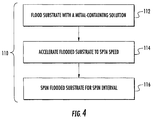
- applying a metal-containing solution to a substrate using a spin coat technique includes flooding the substrate with the metal-containing solution.
- the flooded substrate is accelerated to a predetermined spin speed, as shown with box 114.
- the flooded substrate is spun at the spin speed for a predetermined spin interval, as shown with box 116.
- Spinning metal containing solutions as described herein distributes the metal-containing solution as a metal-containing coat on the substrate such that the metal-containing oxide layer ultimate developed from the metal-containing solution coating has a thickness of about 50 nanometers.
- the predetermined spin speed is about 1,500 rotations per minute and the time interval is about thirty (30) seconds.
- Metal-containing solution 200 includes a stabilizer 210, a solvent 220, a zinc source 230, and a magnesium source 240.
- Zinc source 230 includes a zinc organometallic precursor such as zinc acrylate, zinc 2-methoxyethoxide, zinc acetylacetonate, zinc caprylate, zinc isopropoxide, zinc methacrylate, zinc naphthenate, zinc neodecanoate, zinc octoate, zinc oleate, zinc oxalate, zinc picolinate, zinc stearate, zinc undecylenate, or any other suitable zinc organometallic precursor.
- Magnesium source 240 includes a magnesium organometallic precursor such as bis(2,2,6,6-tetramethyl-3,5-heptanedionato)magnesium, magnesium myristate, magnesium tert-butoxide, magnesium oxalate, magnesium ethoxide, magnesium formate, magnesium naphthenate, magnesium acetylacetonate, or any other suitable magnesium organometallic precursor.
- a magnesium organometallic precursor such as bis(2,2,6,6-tetramethyl-3,5-heptanedionato)magnesium, magnesium myristate, magnesium tert-butoxide, magnesium oxalate, magnesium ethoxide, magnesium formate, magnesium naphthenate, magnesium acetylacetonate, or any other suitable magnesium organometallic precursor.
- the magnesium to zinc by mole ratio in metal-containing solution 200 varies according to the role a given metal-containing oxide layer plays in the layer stack ultimately developed on the substrate.
- spin coat techniques generally allows
- Fig. 6 the effect of stabilizer 210 on metal-containing solution 200 is shown.
- the shelf life of some metal-containing solutions can be influenced by moisture infiltration because infiltrating moisture can cause metal ions to be reduced and thus come out of solution as a precipitate, and alter the ratio of metals within the metal-containing solution. Since the ratio of metals in the metal-containing solution influences the spectral performance of the layer stack ultimately formed using the metal-containing solution, moisture infiltration can cause unintended changes in the tuning of a given detector.
- introducing stabilizer 210 reduces the tendency of moisture absorbed by the metal-containing solution to cause metal to precipitate out of the metal-containing solution.
- Stabilizer 210 generally includes a tri-functional chemical solution deposition additive with an amino alcohol.
- the amino alcohol includes one or more hydroxyl groups and one or more amines.
- the amino alcohol also includes a primary amine, a primary amine and a secondary amine, or primary, secondary, and tertiary amines.
- the amino alcohol may include one or more of monoethanolamine, diethanolamine, triethanolamine, hetpaminol, isoetarine, noepinephrine, propanolamine, shphingosine, or methanolamine.
- the tri-functional chemical solution deposition additive can be diethanolamine.
- the tri-functional chemical solution deposition additive can be added to the organometallic precursor in a ratio of between about 0.05 to 1 and about 1 to 1 of additive to total weight of all metals in the solution.
- the tri-functional chemical solution deposition additive can be added to the organometallic precursor in a 1 to 1 ratio.
- metal-containing solution 200 may have a total metal concentration of about 0.8 moles.
- metal-containing solution 200 includes 0.854 grams (0.009 moles) of diethanolamine, 3.58 milliliters of toluene, 4.829 grams (0.006 moles) of magnesium 2-ethylhexanoate (e.g. Strem 12-1260, 30-40 wt% in toluene, 2.9 wt% magnesium), and 0.647 grams (0.0022 moles) of zinc 2-ethylhexanoate.
- magnesium 2-ethylhexanoate e.g. Strem 12-1260, 30-40 wt% in toluene, 2.9 wt% magnesium
- stabilizer 210 includes diethanolamine at an equimolar concentration to that of magnesium and zinc together.
- the equimolar concentration of diethanolamine with magnesium and zinc in metal-containing solution 200 prevents absorbed moisture from destabilizing the respective bonds between metals and 2-ethylhexanoate in metal-containing solution 200.
- diethanolamine operates as an electron donor, donating its electrons to the respective metal center bound thereto, strengthening the metal to ligand bond therebetween.
- Stabilizer 210 includes diethanolamine.
- Diethanolamine enables metal-containing solution 200 to provide repeatable spin coat application during an extended shelf life interval.
- Diethanolamine i.e. HN(CH 2 CH 2 OH) 2
- HN(CH 2 CH 2 OH) 2 is an amino alcohol like monoethanolamine, triethanolamine, hetpaminol, isoetarine, norepinephrine, propanolamine, sphingosine, and methanolamine that carry a hydroxide (-OH) and an amino (-NH2, NHR, or -NR2) functional groups on an alkane backbone.
- diethanolamine When incorporated into metal-containing solution 200, diethanolamine performs three functions.
- diethanolamine functions as a structure stabilizer before and during spin coating that prevents moisture from the ambient environment attacking the organometallic precursors, particularly zinc sources such as zinc-2-ethylhexanoate compound. This prevents formation of 2-ethylexanoic acid and zinc ions - which would then get reduced and precipitate from the solution as zinc or zinc hydroxide.
- Stabilizer 210 also acts an electron donor to the zinc atom attached to the 2-ethylhexanoate ligands, forming a stronger bond to the 2-ethylhexanoate ligands, and preventing decomposition and thus loss of zinc.
- diethanolamine functions as a rheology aid before and during spin coating.
- metal sources such as metal 2-ethylhexanoates are relatively viscous and incompatible with conventional spin coating techniques. Viscosity is ordinarily reduced in such solutions using solvents like toluene, which is miscible with the organometallic precursor chemicals of metal-containing solution 200, has a low boiling point, and leaves substantially no additional elements or associated imperfections in films produced from solutions containing the solvent.
- Stabilizer compounds such as diethanolamine reduce the viscosity of metal sources like 2-ethylhexanoates more effectively than solvents like toluene, allowing for formulation of metal-containing solutions with greater metal source concentrations than otherwise possible using solvents like toluene.
- diethanolamine functions as a crystal growth aid.
- Magnesium-zinc oxides typically form with hexagonal crystalline structure (wurtzite) with interstitial zinc distributed within the crystal phase.
- the interstitial zinc must be liberated from the crystalline structure during the pyrolysis, calcination, and/or annealing in order for the crystalline structure to 'relax' and adopt a cubic structure - which is solar blind, as shown in Fig. 6 .
- Liberating the interstitial zinc requires energy, which applicants believe is provided by diethanolamine - by burning off to form volatile products, thereby facilitating conversion of the hexagonal structure into cubic structure with consistency sufficient to render resulting magnesium-zinc oxide solar blind.
- metal-containing oxide layers made using the methods described herein can have substantially pure cubic structure, and may, in certain embodiments, have a composition of Mg 0.79 Zn 0.21 O. This can simplify the fabrication of the devices by reducing the need to make such coatings from chemical vapor deposition, molecular beam epitaxial, or sputtering techniques. It can also reduce the cost of UV photodetectors made from such methods, allowing the detection capability of such devices to be inserted in flame detection devices suitable for residential settings.
Landscapes
- Chemical & Material Sciences (AREA)
- Organic Chemistry (AREA)
- Engineering & Computer Science (AREA)
- Materials Engineering (AREA)
- Inorganic Chemistry (AREA)
- Mechanical Engineering (AREA)
- Chemical Kinetics & Catalysis (AREA)
- General Chemical & Material Sciences (AREA)
- Thermal Sciences (AREA)
- Metallurgy (AREA)
- Physics & Mathematics (AREA)
- Life Sciences & Earth Sciences (AREA)
- Wood Science & Technology (AREA)
- Ceramic Engineering (AREA)
- Inorganic Compounds Of Heavy Metals (AREA)
- Photometry And Measurement Of Optical Pulse Characteristics (AREA)
Applications Claiming Priority (1)
| Application Number | Priority Date | Filing Date | Title |
|---|---|---|---|
| US201562198029P | 2015-07-28 | 2015-07-28 |
Publications (3)
| Publication Number | Publication Date |
|---|---|
| EP3133186A2 true EP3133186A2 (de) | 2017-02-22 |
| EP3133186A3 EP3133186A3 (de) | 2017-05-03 |
| EP3133186B1 EP3133186B1 (de) | 2020-03-18 |
Family
ID=56571157
Family Applications (1)
| Application Number | Title | Priority Date | Filing Date |
|---|---|---|---|
| EP16181398.5A Active EP3133186B1 (de) | 2015-07-28 | 2016-07-27 | Ultraviolette photodetektoren und verfahren zur herstellung von ultravioletten photodetektoren |
Country Status (2)
| Country | Link |
|---|---|
| US (1) | US9865766B2 (de) |
| EP (1) | EP3133186B1 (de) |
Families Citing this family (4)
| Publication number | Priority date | Publication date | Assignee | Title |
|---|---|---|---|---|
| EP3631299B1 (de) | 2017-05-30 | 2024-05-22 | Carrier Corporation | Halbleiterfilm und photozellenlichtdetektor |
| CN107358780B (zh) * | 2017-07-30 | 2020-01-03 | 王旭兰 | 基于pn结芯片的智能电火花检测报警系统及其制备方法 |
| CN111211185B (zh) * | 2020-03-19 | 2022-02-08 | 中国科学院长春光学精密机械与物理研究所 | 一种氧化锌基合金薄膜、紫外探测器及其制备方法 |
| EP4286338A1 (de) * | 2022-05-31 | 2023-12-06 | Imec VZW | Gemischtes metalloxid aus magnesium und zink |
Family Cites Families (70)
| Publication number | Priority date | Publication date | Assignee | Title |
|---|---|---|---|---|
| JPS5272596A (en) | 1975-12-15 | 1977-06-17 | Yuwa Sangyo Kk | Composite early fire detecting system and device therefor |
| GB2222908A (en) | 1988-09-14 | 1990-03-21 | Haroon Ahmed | Sensor device |
| US5699035A (en) | 1991-12-13 | 1997-12-16 | Symetrix Corporation | ZnO thin-film varistors and method of making the same |
| US5339070A (en) | 1992-07-21 | 1994-08-16 | Srs Technologies | Combined UV/IR flame detection system |
| DE69428173T2 (de) | 1993-09-30 | 2002-03-28 | Nittan Co., Ltd. | Sensorvorrichtung und elektronische Anlage mit eingebauter Sensorvorrichtung |
| US5494700A (en) | 1994-04-05 | 1996-02-27 | The Curators Of The University Of Missouri | Method of coating a substrate with a metal oxide film from an aqueous solution comprising a metal cation and a polymerizable organic solvent |
| US6064064A (en) | 1996-03-01 | 2000-05-16 | Fire Sentry Corporation | Fire detector |
| GB9805949D0 (en) | 1998-03-19 | 1998-05-20 | Thorn Security | A detector |
| US6166647A (en) | 2000-01-18 | 2000-12-26 | Jaesent Inc. | Fire detector |
| KR100343949B1 (ko) | 2000-01-26 | 2002-07-24 | 한국과학기술연구원 | 상온에서 작동하는 자외선 수광, 발광소자용 ZnO박막의 제조 방법 및 그를 위한 장치 |
| AU2001268756A1 (en) | 2000-06-26 | 2002-01-08 | University Of Maryland | Mgzno based uv detectors |
| WO2002007309A2 (en) | 2000-07-13 | 2002-01-24 | Rutgers, The State University Of New Jersey | Integrated tunable surface acoustic wave technology and sensors provided thereby |
| US6423983B1 (en) | 2000-10-13 | 2002-07-23 | North Carolina State University | Optoelectronic and microelectronic devices including cubic ZnMgO and/or CdMgO alloys |
| AU2002312293A1 (en) | 2002-01-04 | 2003-07-30 | Rutgers, The State University Of New Jersey | SCHOTTKY DIODE WITH SILVER LAYER CONTACTING THE ZnO AND MgxZn1-xO FILMS |
| CN1182593C (zh) | 2002-08-05 | 2004-12-29 | 浙江大学 | 氧化锌紫外光电探测器原型器件的制备方法 |
| US7083880B2 (en) | 2002-08-15 | 2006-08-01 | Freescale Semiconductor, Inc. | Lithographic template and method of formation and use |
| US7172813B2 (en) | 2003-05-20 | 2007-02-06 | Burgener Ii Robert H | Zinc oxide crystal growth substrate |
| US7202794B2 (en) | 2004-07-20 | 2007-04-10 | General Monitors, Inc. | Flame detection system |
| SG124303A1 (en) | 2005-01-18 | 2006-08-30 | Agency Science Tech & Res | Thin films of ferroelectric materials and a methodfor preparing same |
| CN100358159C (zh) | 2005-02-28 | 2007-12-26 | 浙江大学 | 一种日盲区紫外探测器用的薄膜材料及其制造方法 |
| JP5190570B2 (ja) | 2005-03-28 | 2013-04-24 | 国立大学法人岩手大学 | 紫外線センサ素子及びその製造方法 |
| US7333910B2 (en) | 2005-04-26 | 2008-02-19 | Semiconductor Energy Laboratory Co., Ltd. | Fire sensing method and fire sensing system using wireless chip for sensing fire |
| US7541938B1 (en) | 2006-03-29 | 2009-06-02 | Darell Eugene Engelhaupt | Optical flame detection system and method |
| US7566875B2 (en) | 2006-04-13 | 2009-07-28 | Integrated Micro Sensors Inc. | Single-chip monolithic dual-band visible- or solar-blind photodetector |
| US20080036593A1 (en) | 2006-08-04 | 2008-02-14 | The Government Of The Us, As Represented By The Secretary Of The Navy | Volume sensor: data fusion-based, multi-sensor system for advanced damage control |
| CN101210313A (zh) | 2006-12-29 | 2008-07-02 | 中国科学院长春光学精密机械与物理研究所 | 一种电子束蒸发生长MgxZn1-xO薄膜的方法 |
| KR101009532B1 (ko) | 2007-02-26 | 2011-01-18 | 주식회사 엘지화학 | 산화아연계 다층 박막 및 그 제조방법 |
| US7767253B2 (en) | 2007-03-09 | 2010-08-03 | Guardian Industries Corp. | Method of making a photovoltaic device with antireflective coating |
| CN100561742C (zh) | 2007-04-30 | 2009-11-18 | 西安交通大学 | 背照式ZnO基紫外成像固态焦平面探测阵列及其制备 |
| GB0718299D0 (en) | 2007-09-19 | 2007-10-31 | Univ Bristol | Gas sensor |
| CN101285147B (zh) | 2008-06-04 | 2010-11-10 | 中国科学院长春光学精密机械与物理研究所 | 制备单一立方相结构的MgxZn1-xO半导体合金体材料的方法 |
| CN101285173A (zh) | 2008-06-04 | 2008-10-15 | 长春理工大学 | MgxZn1-xO薄膜的双靶射频磁控共溅射制备方法 |
| CN101286535A (zh) | 2008-06-04 | 2008-10-15 | 长春理工大学 | pn结MgxZn1-xO薄膜日盲区紫外探测器件 |
| US8926317B2 (en) | 2008-12-15 | 2015-01-06 | Exxonmobil Research And Engineering Company | System and method for controlling fired heater operations |
| WO2010069353A1 (de) | 2008-12-19 | 2010-06-24 | Minimax Gmbh & Co. Kg | Verfahren und vorrichtung zur früherkennung von bränden |
| JP5275950B2 (ja) | 2009-05-01 | 2013-08-28 | 富士フイルム株式会社 | 積層膜とその製造方法、光電変換素子とその製造方法、及び太陽電池 |
| KR101841752B1 (ko) | 2009-11-03 | 2018-05-04 | 더 리전트 오브 더 유니버시티 오브 캘리포니아 | 저온 수용액 내에서 성장한 다중 표면들 상의 산화 아연 층들에 의해 커버되는 고휘도 발광 다이오드 |
| CN101807619B (zh) | 2010-03-19 | 2012-02-01 | 河南大学 | 一种透明柔性紫外探测器及其制备方法 |
| CN101866983B (zh) | 2010-05-10 | 2014-09-03 | 北京交通大学 | 一种n型掺杂ZnO薄膜的快速响应紫外探测器的制作方法 |
| JP5288299B2 (ja) | 2010-06-21 | 2013-09-11 | 株式会社村田製作所 | 紫外線センサ、及び紫外線センサの製造方法 |
| US8547238B2 (en) | 2010-06-30 | 2013-10-01 | Knowflame, Inc. | Optically redundant fire detector for false alarm rejection |
| CN101969023B (zh) | 2010-08-04 | 2012-05-02 | 长春理工大学 | 在硅衬底上制作台阶生长MgxZn1-xO薄膜的方法 |
| CN101935876A (zh) | 2010-09-14 | 2011-01-05 | 浙江大学 | 一种In掺杂的ZnO单分散纳米颗粒及其合成方法 |
| CN102110735B (zh) | 2010-10-13 | 2012-09-26 | 兰州大学 | 半导体紫外探测传感器及其制备方法 |
| CN201964955U (zh) | 2010-12-31 | 2011-09-07 | 上海神明控制工程有限公司 | 紫外火检探头 |
| KR101192934B1 (ko) | 2011-02-28 | 2012-10-18 | 성균관대학교산학협력단 | 금속산화물 나노구조체를 구비한 자외선 센서 및 이를 응용한 화재경보장치 |
| WO2012121282A1 (ja) | 2011-03-09 | 2012-09-13 | 株式会社 村田製作所 | 紫外線センサ、及び紫外線センサの製造方法 |
| CN102694053B (zh) | 2011-03-22 | 2015-08-05 | 中国科学院微电子研究所 | 半导体器件及其制造方法 |
| JP5779005B2 (ja) | 2011-06-15 | 2015-09-16 | スタンレー電気株式会社 | 紫外線受光素子及びそれらの製造方法 |
| US8878157B2 (en) | 2011-10-20 | 2014-11-04 | University Of Kansas | Semiconductor-graphene hybrids formed using solution growth |
| WO2013130140A1 (en) | 2011-12-01 | 2013-09-06 | University Of Utah Research Foundation | Photonic devices on planar and curved substrates and methods for fabrication thereof |
| CN102569483A (zh) | 2011-12-19 | 2012-07-11 | 北京交通大学 | MgZnO日盲光敏电阻器及其制备方法 |
| CN202633358U (zh) | 2011-12-22 | 2012-12-26 | 安徽康蓝光电股份有限公司 | 量子点结构紫外-可见光电探测器 |
| JP2014011310A (ja) | 2012-06-29 | 2014-01-20 | Toyota Motor Corp | 半導体膜の製造方法 |
| CN103205706B (zh) | 2013-03-08 | 2015-11-18 | 深圳大学 | 一种立方结构MgZnO薄膜的制备方法 |
| CN105190809B (zh) * | 2013-03-12 | 2017-12-12 | 三洋化成工业株式会社 | 铝电解电容器用电解液及使用其的铝电解电容器 |
| US9112074B2 (en) | 2013-03-22 | 2015-08-18 | University Of Central Florida Research Foundation, Inc. | UV photodetectors having semiconductor metal oxide layer |
| CN103219418B (zh) | 2013-03-26 | 2016-07-27 | 华中科技大学 | 一种具有纳米异质复合结构的紫外光探测器及其制备方法 |
| SG10201401787QA (en) | 2013-04-24 | 2014-11-27 | Agency Science Tech & Res | Photo-sensor |
| CN103258869A (zh) | 2013-05-07 | 2013-08-21 | 哈尔滨工业大学 | 基于氧化锌材料的紫外红外双色探测器及其制作方法 |
| CN103346171B (zh) | 2013-05-31 | 2016-04-27 | 西安交通大学 | 一种响应增强型ZnO基光电导探测器及其制备方法 |
| CN103441154B (zh) | 2013-06-26 | 2015-08-12 | 北京科技大学 | 一种ZnO纳米阵列紫外探测器及其制作方法 |
| CN103346199B (zh) | 2013-07-10 | 2015-09-16 | 合肥工业大学 | 基于单层石墨烯/氧化锌纳米棒阵列肖特基结的紫外光电探测器及其制备方法 |
| JP2015023053A (ja) | 2013-07-16 | 2015-02-02 | 株式会社リコー | 電気機械変換素子、液滴吐出ヘッド、液滴吐出装置、画像形成装置、及び、電気機械変換素子の製造方法 |
| CN103441186B (zh) | 2013-08-29 | 2016-04-06 | 江苏大学 | 一种紫外探测器件的制备方法 |
| CN103545397B (zh) | 2013-10-29 | 2016-02-24 | 中国科学院化学研究所 | 薄膜紫外光探测器及其制备方法与应用 |
| CN103915524A (zh) | 2014-04-03 | 2014-07-09 | 浙江大学 | 一种自驱动ZnO基紫外探测器及其制备方法 |
| CN103972310B (zh) | 2014-04-30 | 2016-04-27 | 中国科学院长春光学精密机械与物理研究所 | 一种氧化锌基p型材料的制备方法 |
| CN104504838A (zh) | 2014-12-15 | 2015-04-08 | 长春理工大学 | 采用氧化锌基半导体薄膜的紫外火焰探测器 |
| CN104617180B (zh) | 2015-01-16 | 2018-01-09 | 浙江大学 | 一种石墨烯/氮化硼/氧化锌紫外探测器及其制备方法 |
-
2016
- 2016-07-22 US US15/217,952 patent/US9865766B2/en active Active
- 2016-07-27 EP EP16181398.5A patent/EP3133186B1/de active Active
Non-Patent Citations (1)
| Title |
|---|
| None |
Also Published As
| Publication number | Publication date |
|---|---|
| US20170033256A1 (en) | 2017-02-02 |
| EP3133186B1 (de) | 2020-03-18 |
| US9865766B2 (en) | 2018-01-09 |
| EP3133186A3 (de) | 2017-05-03 |
Similar Documents
| Publication | Publication Date | Title |
|---|---|---|
| EP3133186B1 (de) | Ultraviolette photodetektoren und verfahren zur herstellung von ultravioletten photodetektoren | |
| US8865628B2 (en) | Solution for forming rare-earth superconductive film and production method thereof | |
| Armelao et al. | A sol–gel approach to nanophasic copper oxide thin films | |
| JP6192646B2 (ja) | 高性能な電気的に安定した半導電性の金属酸化物層の製造法、当該方法により製造された層および当該層の使用 | |
| JP6161764B2 (ja) | 酸化インジウム含有層の製造方法 | |
| Nian et al. | Sol–gel derived N-doped ZnO thin films | |
| EP2409337A1 (de) | Solarzellen mit einer verkapselungsschicht auf basis von polysilazan | |
| US10453988B2 (en) | Methods for creating cadmium telluride (CdTe) and related alloy film | |
| Meza-Rocha et al. | Enhanced photoluminescence of Y2O3: Er3+ thin films by Li+ co-doping | |
| US9130084B2 (en) | Liquid precursor for deposition of copper selenide and method of preparing the same | |
| CA2447626A1 (en) | Single source sputtering of thioaluminate phosphor films | |
| Park et al. | Electrical and optical properties of in and Al doped ZnO thin film | |
| US20100015340A1 (en) | COMPOSITIONS AND METHODS FOR THE MANUFACTURE OF RARE EARTH METAL-Ba2Cu3O7-delta THIN FILMS | |
| Engberg et al. | Investigation of Cu2ZnSnS4 nanoparticles for thin-film solar cell applications | |
| Dawley et al. | High Jc YBa2Cu3O7-δ films via rapid, low pO2 pyrolysis | |
| US20240385351A1 (en) | Optical laminate comprising thermochromic layer having excellent optical properties due to control of photonic evaporation and photonic sintering conditions, and manufacturing method therefor | |
| Khaldi et al. | Ultra-shallow p-type doping of silicon by performing atomic layer deposition of Al 2 O 3 thin films onto SiO 2/Si | |
| JP4729766B2 (ja) | 超電導酸化物材料の製造方法 | |
| DE102012025429A1 (de) | Verfahren zur Dotierung von Halbleitersubstraten sowie dotiertes Halbleitersubstrat | |
| Popovici et al. | Optical and magnetic properties of Co-doped TiO2 thin films grown by pulsed laser deposition | |
| JP5273561B2 (ja) | 超電導膜の製造方法 | |
| Bel-Hadj-Tahar | Structural and electro-optical properties of sol-gel processed Cd2SnO4 powder and nanocrystalline films | |
| DE102008032127A1 (de) | Sol und Verfahren zur Herstellung einer Delafossit-Mischoxidschicht-Struktur auf einem Substrat sowie mit einem Mischoxid beschichtetes Substrat | |
| Luo et al. | Deposition and tunable photoluminescence of Zn1–x (Mg, Cd) xO film system | |
| Blondeau-Patissier et al. | MoOx (x≤ 2) ultrathin film growth from reactions between metallic molybdenum and TiO2 surfaces |
Legal Events
| Date | Code | Title | Description |
|---|---|---|---|
| PUAI | Public reference made under article 153(3) epc to a published international application that has entered the european phase |
Free format text: ORIGINAL CODE: 0009012 |
|
| STAA | Information on the status of an ep patent application or granted ep patent |
Free format text: STATUS: THE APPLICATION HAS BEEN PUBLISHED |
|
| AK | Designated contracting states |
Kind code of ref document: A2 Designated state(s): AL AT BE BG CH CY CZ DE DK EE ES FI FR GB GR HR HU IE IS IT LI LT LU LV MC MK MT NL NO PL PT RO RS SE SI SK SM TR |
|
| AX | Request for extension of the european patent |
Extension state: BA ME |
|
| PUAL | Search report despatched |
Free format text: ORIGINAL CODE: 0009013 |
|
| AK | Designated contracting states |
Kind code of ref document: A3 Designated state(s): AL AT BE BG CH CY CZ DE DK EE ES FI FR GB GR HR HU IE IS IT LI LT LU LV MC MK MT NL NO PL PT RO RS SE SI SK SM TR |
|
| AX | Request for extension of the european patent |
Extension state: BA ME |
|
| RIC1 | Information provided on ipc code assigned before grant |
Ipc: C23C 18/12 20060101AFI20170330BHEP Ipc: G01J 1/42 20060101ALI20170330BHEP |
|
| STAA | Information on the status of an ep patent application or granted ep patent |
Free format text: STATUS: REQUEST FOR EXAMINATION WAS MADE |
|
| 17P | Request for examination filed |
Effective date: 20171103 |
|
| RBV | Designated contracting states (corrected) |
Designated state(s): AL AT BE BG CH CY CZ DE DK EE ES FI FR GB GR HR HU IE IS IT LI LT LU LV MC MK MT NL NO PL PT RO RS SE SI SK SM TR |
|
| STAA | Information on the status of an ep patent application or granted ep patent |
Free format text: STATUS: EXAMINATION IS IN PROGRESS |
|
| 17Q | First examination report despatched |
Effective date: 20190423 |
|
| GRAP | Despatch of communication of intention to grant a patent |
Free format text: ORIGINAL CODE: EPIDOSNIGR1 |
|
| STAA | Information on the status of an ep patent application or granted ep patent |
Free format text: STATUS: GRANT OF PATENT IS INTENDED |
|
| RIC1 | Information provided on ipc code assigned before grant |
Ipc: G01J 1/42 20060101ALN20190911BHEP Ipc: C23C 18/12 20060101AFI20190911BHEP |
|
| INTG | Intention to grant announced |
Effective date: 20191007 |
|
| GRAS | Grant fee paid |
Free format text: ORIGINAL CODE: EPIDOSNIGR3 |
|
| GRAA | (expected) grant |
Free format text: ORIGINAL CODE: 0009210 |
|
| STAA | Information on the status of an ep patent application or granted ep patent |
Free format text: STATUS: THE PATENT HAS BEEN GRANTED |
|
| AK | Designated contracting states |
Kind code of ref document: B1 Designated state(s): AL AT BE BG CH CY CZ DE DK EE ES FI FR GB GR HR HU IE IS IT LI LT LU LV MC MK MT NL NO PL PT RO RS SE SI SK SM TR |
|
| REG | Reference to a national code |
Ref country code: GB Ref legal event code: FG4D |
|
| REG | Reference to a national code |
Ref country code: DE Ref legal event code: R096 Ref document number: 602016031870 Country of ref document: DE |
|
| REG | Reference to a national code |
Ref country code: AT Ref legal event code: REF Ref document number: 1245996 Country of ref document: AT Kind code of ref document: T Effective date: 20200415 Ref country code: IE Ref legal event code: FG4D |
|
| REG | Reference to a national code |
Ref country code: NO Ref legal event code: T2 Effective date: 20200318 |
|
| PG25 | Lapsed in a contracting state [announced via postgrant information from national office to epo] |
Ref country code: FI Free format text: LAPSE BECAUSE OF FAILURE TO SUBMIT A TRANSLATION OF THE DESCRIPTION OR TO PAY THE FEE WITHIN THE PRESCRIBED TIME-LIMIT Effective date: 20200318 Ref country code: RS Free format text: LAPSE BECAUSE OF FAILURE TO SUBMIT A TRANSLATION OF THE DESCRIPTION OR TO PAY THE FEE WITHIN THE PRESCRIBED TIME-LIMIT Effective date: 20200318 |
|
| REG | Reference to a national code |
Ref country code: NL Ref legal event code: MP Effective date: 20200318 |
|
| PG25 | Lapsed in a contracting state [announced via postgrant information from national office to epo] |
Ref country code: GR Free format text: LAPSE BECAUSE OF FAILURE TO SUBMIT A TRANSLATION OF THE DESCRIPTION OR TO PAY THE FEE WITHIN THE PRESCRIBED TIME-LIMIT Effective date: 20200619 Ref country code: HR Free format text: LAPSE BECAUSE OF FAILURE TO SUBMIT A TRANSLATION OF THE DESCRIPTION OR TO PAY THE FEE WITHIN THE PRESCRIBED TIME-LIMIT Effective date: 20200318 Ref country code: LV Free format text: LAPSE BECAUSE OF FAILURE TO SUBMIT A TRANSLATION OF THE DESCRIPTION OR TO PAY THE FEE WITHIN THE PRESCRIBED TIME-LIMIT Effective date: 20200318 Ref country code: SE Free format text: LAPSE BECAUSE OF FAILURE TO SUBMIT A TRANSLATION OF THE DESCRIPTION OR TO PAY THE FEE WITHIN THE PRESCRIBED TIME-LIMIT Effective date: 20200318 Ref country code: BG Free format text: LAPSE BECAUSE OF FAILURE TO SUBMIT A TRANSLATION OF THE DESCRIPTION OR TO PAY THE FEE WITHIN THE PRESCRIBED TIME-LIMIT Effective date: 20200618 |
|
| REG | Reference to a national code |
Ref country code: LT Ref legal event code: MG4D |
|
| PG25 | Lapsed in a contracting state [announced via postgrant information from national office to epo] |
Ref country code: NL Free format text: LAPSE BECAUSE OF FAILURE TO SUBMIT A TRANSLATION OF THE DESCRIPTION OR TO PAY THE FEE WITHIN THE PRESCRIBED TIME-LIMIT Effective date: 20200318 |
|
| PG25 | Lapsed in a contracting state [announced via postgrant information from national office to epo] |
Ref country code: PT Free format text: LAPSE BECAUSE OF FAILURE TO SUBMIT A TRANSLATION OF THE DESCRIPTION OR TO PAY THE FEE WITHIN THE PRESCRIBED TIME-LIMIT Effective date: 20200812 Ref country code: LT Free format text: LAPSE BECAUSE OF FAILURE TO SUBMIT A TRANSLATION OF THE DESCRIPTION OR TO PAY THE FEE WITHIN THE PRESCRIBED TIME-LIMIT Effective date: 20200318 Ref country code: SM Free format text: LAPSE BECAUSE OF FAILURE TO SUBMIT A TRANSLATION OF THE DESCRIPTION OR TO PAY THE FEE WITHIN THE PRESCRIBED TIME-LIMIT Effective date: 20200318 Ref country code: EE Free format text: LAPSE BECAUSE OF FAILURE TO SUBMIT A TRANSLATION OF THE DESCRIPTION OR TO PAY THE FEE WITHIN THE PRESCRIBED TIME-LIMIT Effective date: 20200318 Ref country code: RO Free format text: LAPSE BECAUSE OF FAILURE TO SUBMIT A TRANSLATION OF THE DESCRIPTION OR TO PAY THE FEE WITHIN THE PRESCRIBED TIME-LIMIT Effective date: 20200318 Ref country code: CZ Free format text: LAPSE BECAUSE OF FAILURE TO SUBMIT A TRANSLATION OF THE DESCRIPTION OR TO PAY THE FEE WITHIN THE PRESCRIBED TIME-LIMIT Effective date: 20200318 Ref country code: IS Free format text: LAPSE BECAUSE OF FAILURE TO SUBMIT A TRANSLATION OF THE DESCRIPTION OR TO PAY THE FEE WITHIN THE PRESCRIBED TIME-LIMIT Effective date: 20200718 Ref country code: SK Free format text: LAPSE BECAUSE OF FAILURE TO SUBMIT A TRANSLATION OF THE DESCRIPTION OR TO PAY THE FEE WITHIN THE PRESCRIBED TIME-LIMIT Effective date: 20200318 |
|
| REG | Reference to a national code |
Ref country code: AT Ref legal event code: MK05 Ref document number: 1245996 Country of ref document: AT Kind code of ref document: T Effective date: 20200318 |
|
| REG | Reference to a national code |
Ref country code: DE Ref legal event code: R097 Ref document number: 602016031870 Country of ref document: DE |
|
| PLBE | No opposition filed within time limit |
Free format text: ORIGINAL CODE: 0009261 |
|
| STAA | Information on the status of an ep patent application or granted ep patent |
Free format text: STATUS: NO OPPOSITION FILED WITHIN TIME LIMIT |
|
| PG25 | Lapsed in a contracting state [announced via postgrant information from national office to epo] |
Ref country code: IT Free format text: LAPSE BECAUSE OF FAILURE TO SUBMIT A TRANSLATION OF THE DESCRIPTION OR TO PAY THE FEE WITHIN THE PRESCRIBED TIME-LIMIT Effective date: 20200318 Ref country code: ES Free format text: LAPSE BECAUSE OF FAILURE TO SUBMIT A TRANSLATION OF THE DESCRIPTION OR TO PAY THE FEE WITHIN THE PRESCRIBED TIME-LIMIT Effective date: 20200318 Ref country code: AT Free format text: LAPSE BECAUSE OF FAILURE TO SUBMIT A TRANSLATION OF THE DESCRIPTION OR TO PAY THE FEE WITHIN THE PRESCRIBED TIME-LIMIT Effective date: 20200318 Ref country code: DK Free format text: LAPSE BECAUSE OF FAILURE TO SUBMIT A TRANSLATION OF THE DESCRIPTION OR TO PAY THE FEE WITHIN THE PRESCRIBED TIME-LIMIT Effective date: 20200318 |
|
| 26N | No opposition filed |
Effective date: 20201221 |
|
| PG25 | Lapsed in a contracting state [announced via postgrant information from national office to epo] |
Ref country code: MC Free format text: LAPSE BECAUSE OF FAILURE TO SUBMIT A TRANSLATION OF THE DESCRIPTION OR TO PAY THE FEE WITHIN THE PRESCRIBED TIME-LIMIT Effective date: 20200318 Ref country code: PL Free format text: LAPSE BECAUSE OF FAILURE TO SUBMIT A TRANSLATION OF THE DESCRIPTION OR TO PAY THE FEE WITHIN THE PRESCRIBED TIME-LIMIT Effective date: 20200318 |
|
| REG | Reference to a national code |
Ref country code: CH Ref legal event code: PL |
|
| REG | Reference to a national code |
Ref country code: BE Ref legal event code: MM Effective date: 20200731 |
|
| PG25 | Lapsed in a contracting state [announced via postgrant information from national office to epo] |
Ref country code: FR Free format text: LAPSE BECAUSE OF NON-PAYMENT OF DUE FEES Effective date: 20200731 Ref country code: CH Free format text: LAPSE BECAUSE OF NON-PAYMENT OF DUE FEES Effective date: 20200731 Ref country code: LU Free format text: LAPSE BECAUSE OF NON-PAYMENT OF DUE FEES Effective date: 20200727 Ref country code: LI Free format text: LAPSE BECAUSE OF NON-PAYMENT OF DUE FEES Effective date: 20200731 |
|
| PG25 | Lapsed in a contracting state [announced via postgrant information from national office to epo] |
Ref country code: BE Free format text: LAPSE BECAUSE OF NON-PAYMENT OF DUE FEES Effective date: 20200731 Ref country code: SI Free format text: LAPSE BECAUSE OF FAILURE TO SUBMIT A TRANSLATION OF THE DESCRIPTION OR TO PAY THE FEE WITHIN THE PRESCRIBED TIME-LIMIT Effective date: 20200318 |
|
| PG25 | Lapsed in a contracting state [announced via postgrant information from national office to epo] |
Ref country code: IE Free format text: LAPSE BECAUSE OF NON-PAYMENT OF DUE FEES Effective date: 20200727 |
|
| PG25 | Lapsed in a contracting state [announced via postgrant information from national office to epo] |
Ref country code: TR Free format text: LAPSE BECAUSE OF FAILURE TO SUBMIT A TRANSLATION OF THE DESCRIPTION OR TO PAY THE FEE WITHIN THE PRESCRIBED TIME-LIMIT Effective date: 20200318 Ref country code: MT Free format text: LAPSE BECAUSE OF FAILURE TO SUBMIT A TRANSLATION OF THE DESCRIPTION OR TO PAY THE FEE WITHIN THE PRESCRIBED TIME-LIMIT Effective date: 20200318 Ref country code: CY Free format text: LAPSE BECAUSE OF FAILURE TO SUBMIT A TRANSLATION OF THE DESCRIPTION OR TO PAY THE FEE WITHIN THE PRESCRIBED TIME-LIMIT Effective date: 20200318 |
|
| PG25 | Lapsed in a contracting state [announced via postgrant information from national office to epo] |
Ref country code: MK Free format text: LAPSE BECAUSE OF FAILURE TO SUBMIT A TRANSLATION OF THE DESCRIPTION OR TO PAY THE FEE WITHIN THE PRESCRIBED TIME-LIMIT Effective date: 20200318 Ref country code: AL Free format text: LAPSE BECAUSE OF FAILURE TO SUBMIT A TRANSLATION OF THE DESCRIPTION OR TO PAY THE FEE WITHIN THE PRESCRIBED TIME-LIMIT Effective date: 20200318 |
|
| PGFP | Annual fee paid to national office [announced via postgrant information from national office to epo] |
Ref country code: GB Payment date: 20250619 Year of fee payment: 10 |
|
| PGFP | Annual fee paid to national office [announced via postgrant information from national office to epo] |
Ref country code: NO Payment date: 20250623 Year of fee payment: 10 |
|
| PGFP | Annual fee paid to national office [announced via postgrant information from national office to epo] |
Ref country code: DE Payment date: 20250620 Year of fee payment: 10 |
|
| REG | Reference to a national code |
Ref country code: GB Ref legal event code: 732E Free format text: REGISTERED BETWEEN 20260305 AND 20260311 |