EP3130305B1 - Medizinischer haltearm - Google Patents
Medizinischer haltearm Download PDFInfo
- Publication number
- EP3130305B1 EP3130305B1 EP15180826.8A EP15180826A EP3130305B1 EP 3130305 B1 EP3130305 B1 EP 3130305B1 EP 15180826 A EP15180826 A EP 15180826A EP 3130305 B1 EP3130305 B1 EP 3130305B1
- Authority
- EP
- European Patent Office
- Prior art keywords
- joint
- holding apparatus
- status
- holding device
- display
- Prior art date
- Legal status (The legal status is an assumption and is not a legal conclusion. Google has not performed a legal analysis and makes no representation as to the accuracy of the status listed.)
- Active
Links
- 238000000034 method Methods 0.000 claims description 6
- 238000004891 communication Methods 0.000 claims description 2
- 230000008859 change Effects 0.000 description 7
- 239000003086 colorant Substances 0.000 description 6
- 238000012800 visualization Methods 0.000 description 6
- 230000008878 coupling Effects 0.000 description 4
- 238000010168 coupling process Methods 0.000 description 4
- 238000005859 coupling reaction Methods 0.000 description 4
- 238000012546 transfer Methods 0.000 description 4
- 230000009471 action Effects 0.000 description 3
- 238000011161 development Methods 0.000 description 3
- 230000007246 mechanism Effects 0.000 description 3
- 230000003287 optical effect Effects 0.000 description 3
- 238000010586 diagram Methods 0.000 description 2
- 208000014674 injury Diseases 0.000 description 2
- 238000012545 processing Methods 0.000 description 2
- 230000003068 static effect Effects 0.000 description 2
- 206010002091 Anaesthesia Diseases 0.000 description 1
- 208000027418 Wounds and injury Diseases 0.000 description 1
- 238000012084 abdominal surgery Methods 0.000 description 1
- 230000001133 acceleration Effects 0.000 description 1
- 230000037005 anaesthesia Effects 0.000 description 1
- 230000008901 benefit Effects 0.000 description 1
- 230000005540 biological transmission Effects 0.000 description 1
- 210000000078 claw Anatomy 0.000 description 1
- 230000006378 damage Effects 0.000 description 1
- 230000007547 defect Effects 0.000 description 1
- 238000013461 design Methods 0.000 description 1
- 201000010099 disease Diseases 0.000 description 1
- 208000037265 diseases, disorders, signs and symptoms Diseases 0.000 description 1
- 230000000694 effects Effects 0.000 description 1
- 238000002674 endoscopic surgery Methods 0.000 description 1
- 238000005286 illumination Methods 0.000 description 1
- 230000005923 long-lasting effect Effects 0.000 description 1
- 230000001105 regulatory effect Effects 0.000 description 1
- 239000000126 substance Substances 0.000 description 1
- 238000001356 surgical procedure Methods 0.000 description 1
- 238000012360 testing method Methods 0.000 description 1
- 230000008733 trauma Effects 0.000 description 1
- 230000000007 visual effect Effects 0.000 description 1
Images


Classifications
-
- A—HUMAN NECESSITIES
- A61—MEDICAL OR VETERINARY SCIENCE; HYGIENE
- A61B—DIAGNOSIS; SURGERY; IDENTIFICATION
- A61B90/00—Instruments, implements or accessories specially adapted for surgery or diagnosis and not covered by any of the groups A61B1/00 - A61B50/00, e.g. for luxation treatment or for protecting wound edges
- A61B90/50—Supports for surgical instruments, e.g. articulated arms
-
- A—HUMAN NECESSITIES
- A61—MEDICAL OR VETERINARY SCIENCE; HYGIENE
- A61B—DIAGNOSIS; SURGERY; IDENTIFICATION
- A61B17/00—Surgical instruments, devices or methods, e.g. tourniquets
- A61B17/02—Surgical instruments, devices or methods, e.g. tourniquets for holding wounds open; Tractors
-
- A—HUMAN NECESSITIES
- A61—MEDICAL OR VETERINARY SCIENCE; HYGIENE
- A61B—DIAGNOSIS; SURGERY; IDENTIFICATION
- A61B34/00—Computer-aided surgery; Manipulators or robots specially adapted for use in surgery
- A61B34/30—Surgical robots
-
- B—PERFORMING OPERATIONS; TRANSPORTING
- B25—HAND TOOLS; PORTABLE POWER-DRIVEN TOOLS; MANIPULATORS
- B25J—MANIPULATORS; CHAMBERS PROVIDED WITH MANIPULATION DEVICES
- B25J1/00—Manipulators positioned in space by hand
- B25J1/02—Manipulators positioned in space by hand articulated or flexible
-
- B—PERFORMING OPERATIONS; TRANSPORTING
- B25—HAND TOOLS; PORTABLE POWER-DRIVEN TOOLS; MANIPULATORS
- B25J—MANIPULATORS; CHAMBERS PROVIDED WITH MANIPULATION DEVICES
- B25J1/00—Manipulators positioned in space by hand
- B25J1/12—Manipulators positioned in space by hand having means for attachment to a support stand
-
- B—PERFORMING OPERATIONS; TRANSPORTING
- B25—HAND TOOLS; PORTABLE POWER-DRIVEN TOOLS; MANIPULATORS
- B25J—MANIPULATORS; CHAMBERS PROVIDED WITH MANIPULATION DEVICES
- B25J11/00—Manipulators not otherwise provided for
- B25J11/0005—Manipulators having means for high-level communication with users, e.g. speech generator, face recognition means
-
- B—PERFORMING OPERATIONS; TRANSPORTING
- B25—HAND TOOLS; PORTABLE POWER-DRIVEN TOOLS; MANIPULATORS
- B25J—MANIPULATORS; CHAMBERS PROVIDED WITH MANIPULATION DEVICES
- B25J11/00—Manipulators not otherwise provided for
- B25J11/005—Manipulators for mechanical processing tasks
-
- B—PERFORMING OPERATIONS; TRANSPORTING
- B25—HAND TOOLS; PORTABLE POWER-DRIVEN TOOLS; MANIPULATORS
- B25J—MANIPULATORS; CHAMBERS PROVIDED WITH MANIPULATION DEVICES
- B25J13/00—Controls for manipulators
- B25J13/02—Hand grip control means
-
- B—PERFORMING OPERATIONS; TRANSPORTING
- B25—HAND TOOLS; PORTABLE POWER-DRIVEN TOOLS; MANIPULATORS
- B25J—MANIPULATORS; CHAMBERS PROVIDED WITH MANIPULATION DEVICES
- B25J13/00—Controls for manipulators
- B25J13/08—Controls for manipulators by means of sensing devices, e.g. viewing or touching devices
- B25J13/081—Touching devices, e.g. pressure-sensitive
- B25J13/082—Grasping-force detectors
-
- B—PERFORMING OPERATIONS; TRANSPORTING
- B25—HAND TOOLS; PORTABLE POWER-DRIVEN TOOLS; MANIPULATORS
- B25J—MANIPULATORS; CHAMBERS PROVIDED WITH MANIPULATION DEVICES
- B25J13/00—Controls for manipulators
- B25J13/08—Controls for manipulators by means of sensing devices, e.g. viewing or touching devices
- B25J13/081—Touching devices, e.g. pressure-sensitive
- B25J13/084—Tactile sensors
-
- B—PERFORMING OPERATIONS; TRANSPORTING
- B25—HAND TOOLS; PORTABLE POWER-DRIVEN TOOLS; MANIPULATORS
- B25J—MANIPULATORS; CHAMBERS PROVIDED WITH MANIPULATION DEVICES
- B25J13/00—Controls for manipulators
- B25J13/08—Controls for manipulators by means of sensing devices, e.g. viewing or touching devices
- B25J13/085—Force or torque sensors
-
- B—PERFORMING OPERATIONS; TRANSPORTING
- B25—HAND TOOLS; PORTABLE POWER-DRIVEN TOOLS; MANIPULATORS
- B25J—MANIPULATORS; CHAMBERS PROVIDED WITH MANIPULATION DEVICES
- B25J19/00—Accessories fitted to manipulators, e.g. for monitoring, for viewing; Safety devices combined with or specially adapted for use in connection with manipulators
- B25J19/06—Safety devices
-
- B—PERFORMING OPERATIONS; TRANSPORTING
- B25—HAND TOOLS; PORTABLE POWER-DRIVEN TOOLS; MANIPULATORS
- B25J—MANIPULATORS; CHAMBERS PROVIDED WITH MANIPULATION DEVICES
- B25J9/00—Programme-controlled manipulators
- B25J9/06—Programme-controlled manipulators characterised by multi-articulated arms
-
- F—MECHANICAL ENGINEERING; LIGHTING; HEATING; WEAPONS; BLASTING
- F16—ENGINEERING ELEMENTS AND UNITS; GENERAL MEASURES FOR PRODUCING AND MAINTAINING EFFECTIVE FUNCTIONING OF MACHINES OR INSTALLATIONS; THERMAL INSULATION IN GENERAL
- F16M—FRAMES, CASINGS OR BEDS OF ENGINES, MACHINES OR APPARATUS, NOT SPECIFIC TO ENGINES, MACHINES OR APPARATUS PROVIDED FOR ELSEWHERE; STANDS; SUPPORTS
- F16M13/00—Other supports for positioning apparatus or articles; Means for steadying hand-held apparatus or articles
- F16M13/02—Other supports for positioning apparatus or articles; Means for steadying hand-held apparatus or articles for supporting on, or attaching to, an object, e.g. tree, gate, window-frame, cycle
- F16M13/022—Other supports for positioning apparatus or articles; Means for steadying hand-held apparatus or articles for supporting on, or attaching to, an object, e.g. tree, gate, window-frame, cycle repositionable
-
- A—HUMAN NECESSITIES
- A61—MEDICAL OR VETERINARY SCIENCE; HYGIENE
- A61B—DIAGNOSIS; SURGERY; IDENTIFICATION
- A61B17/00—Surgical instruments, devices or methods, e.g. tourniquets
- A61B2017/00017—Electrical control of surgical instruments
- A61B2017/00115—Electrical control of surgical instruments with audible or visual output
-
- A—HUMAN NECESSITIES
- A61—MEDICAL OR VETERINARY SCIENCE; HYGIENE
- A61B—DIAGNOSIS; SURGERY; IDENTIFICATION
- A61B90/00—Instruments, implements or accessories specially adapted for surgery or diagnosis and not covered by any of the groups A61B1/00 - A61B50/00, e.g. for luxation treatment or for protecting wound edges
- A61B90/08—Accessories or related features not otherwise provided for
- A61B2090/0807—Indication means
-
- A—HUMAN NECESSITIES
- A61—MEDICAL OR VETERINARY SCIENCE; HYGIENE
- A61B—DIAGNOSIS; SURGERY; IDENTIFICATION
- A61B90/00—Instruments, implements or accessories specially adapted for surgery or diagnosis and not covered by any of the groups A61B1/00 - A61B50/00, e.g. for luxation treatment or for protecting wound edges
- A61B90/36—Image-producing devices or illumination devices not otherwise provided for
- A61B90/37—Surgical systems with images on a monitor during operation
- A61B2090/372—Details of monitor hardware
-
- A—HUMAN NECESSITIES
- A61—MEDICAL OR VETERINARY SCIENCE; HYGIENE
- A61B—DIAGNOSIS; SURGERY; IDENTIFICATION
- A61B90/00—Instruments, implements or accessories specially adapted for surgery or diagnosis and not covered by any of the groups A61B1/00 - A61B50/00, e.g. for luxation treatment or for protecting wound edges
- A61B90/50—Supports for surgical instruments, e.g. articulated arms
- A61B2090/508—Supports for surgical instruments, e.g. articulated arms with releasable brake mechanisms
-
- A—HUMAN NECESSITIES
- A61—MEDICAL OR VETERINARY SCIENCE; HYGIENE
- A61B—DIAGNOSIS; SURGERY; IDENTIFICATION
- A61B90/00—Instruments, implements or accessories specially adapted for surgery or diagnosis and not covered by any of the groups A61B1/00 - A61B50/00, e.g. for luxation treatment or for protecting wound edges
- A61B90/50—Supports for surgical instruments, e.g. articulated arms
- A61B90/57—Accessory clamps
- A61B2090/571—Accessory clamps for clamping a support arm to a bed or other supports
-
- A—HUMAN NECESSITIES
- A61—MEDICAL OR VETERINARY SCIENCE; HYGIENE
- A61B—DIAGNOSIS; SURGERY; IDENTIFICATION
- A61B90/00—Instruments, implements or accessories specially adapted for surgery or diagnosis and not covered by any of the groups A61B1/00 - A61B50/00, e.g. for luxation treatment or for protecting wound edges
- A61B90/90—Identification means for patients or instruments, e.g. tags
- A61B90/94—Identification means for patients or instruments, e.g. tags coded with symbols, e.g. text
- A61B90/96—Identification means for patients or instruments, e.g. tags coded with symbols, e.g. text using barcodes
-
- B—PERFORMING OPERATIONS; TRANSPORTING
- B25—HAND TOOLS; PORTABLE POWER-DRIVEN TOOLS; MANIPULATORS
- B25J—MANIPULATORS; CHAMBERS PROVIDED WITH MANIPULATION DEVICES
- B25J18/00—Arms
- B25J18/02—Arms extensible
- B25J18/04—Arms extensible rotatable
-
- F—MECHANICAL ENGINEERING; LIGHTING; HEATING; WEAPONS; BLASTING
- F16—ENGINEERING ELEMENTS AND UNITS; GENERAL MEASURES FOR PRODUCING AND MAINTAINING EFFECTIVE FUNCTIONING OF MACHINES OR INSTALLATIONS; THERMAL INSULATION IN GENERAL
- F16M—FRAMES, CASINGS OR BEDS OF ENGINES, MACHINES OR APPARATUS, NOT SPECIFIC TO ENGINES, MACHINES OR APPARATUS PROVIDED FOR ELSEWHERE; STANDS; SUPPORTS
- F16M2200/00—Details of stands or supports
- F16M2200/02—Locking means
- F16M2200/021—Locking means for rotational movement
Definitions
- the invention relates to a holding device, in particular a holding arm and / or stand, for medical purposes, in particular for holding surgical mechatronic assistance systems and / or surgical instruments.
- the invention also relates to a method.
- Holding arms which fall under holding devices of the type mentioned at the beginning, have been known for a long time and are used in surgery in particular to relieve a surgeon of static holding work.
- a holding arm is used to hold a mechatronic assistance system and / or a surgical instrument, such as a manipulator, an endoscope, a surgical clamp and the like.
- the holding arms mentioned at the beginning have proven particularly useful for holding endoscopes.
- endoscopic surgery a surgeon usually operates an instrument with both hands while an assistant holds the endoscope in order to visualize the operating field on a screen. Holding the endoscope for a long period of time is very tiring. For this reason, the aforementioned holding arms are increasingly being used.
- Such a holding arm is for example off DE 195 26 915 B4 known.
- the holding device for medical purposes disclosed there has a connection part and a holder for surgical tools as well as an arm arranged between the holder and the connection part.
- the arm is connected to the holder and the connection part or to an adjacent arm via a joint and is coupled with a pneumatically actuated device for the optional fixing and releasing of the joints, this device fixing the joints under the action of a braking force on the joint and mechanical spring wherein the device can be pneumatically transferred into a state releasing the joint against the force of this spring.
- an actuating member is arranged, by means of which a valve can be opened so that the individual joints of the arm can be adjusted. When the actuator is released, the valve is closed again so that the joints are fixed.
- the disadvantage is that all joints are opened simultaneously with the holding arm, which can make positioning difficult.
- a similar support arm is in EP 1 958 587 B1 disclosed.
- the holding arm disclosed there also has several joints, and a touch-sensitive sensor is provided for actuating the joints.
- the sensor is arranged on the holding arm adjacent to the medical instrument, so that when the medical instrument is grasped the operator comes into contact with the touch-sensitive sensor, whereby all joints of the holding arm are released.
- the above-mentioned problem of poor positioning also occurs here.
- DE 10 2011 004 371 A1 discloses a holding arm for holding surgical instruments. This comprises at least one controllable joint that can be switched into a movable state and into a locked state.
- a controllable clamping device can be switched into an open state and into a clamped state in order to grip a surgical instrument.
- Remote control commands can be received by means of a control unit and these can be converted into switching operations of the joint and / or the clamping device.
- a remote control unit is preferably included in an arrangement with an operating table.
- a carrying system for carrying or supporting medical devices in a treatment room is also known.
- the support system has a stand for mounting in the treatment room, at least one joint or at least one mechanism with which the stand can be moved in the treatment room, an operating aid for operating at least part of the Carrying system to control a movement of the tripod and a feedback system for generating a signal or a feedback via an actuation of the correlating part of the carrying system with the operating aid.
- the carrying system is characterized in that the feedback system has at least one luminous element which identifies or characterizes the part of the carrying system or the corresponding joint or the corresponding mechanism locally on the stand at the respective point of the mechanism or on the corresponding joint, typically by Lighting.
- the carrying system comprises two arms which can be pivoted about pivot axes arranged parallel to one another.
- a short cylindrical piece is provided at each joint, and an oval-shaped lamp is arranged in this cylindrical piece.
- the control unit is designed as a remote control and has buttons for releasing each joint. The corresponding lamp on the corresponding joint lights up when the button is pressed. This should make it easier, especially in dark operating rooms, to press the correct button and thus release the correct joint or receive feedback on it.
- the disadvantage here is that a lamp lights up only when the corresponding button on the remote control is pressed, that is, the joint is actuated.
- EP 0 855 002 A1 a holding arm in which forces or moments resulting from an imbalance are measured in order to be able to carry out a targeted adjustment of counterweights.
- the object of the present invention is therefore to improve the safety of the operation of such a holding device and its ease of use.
- the invention solves the problem with a holding device of the type mentioned at the beginning with a proximal end for attaching the holding device to a base and a distal end for receiving an attachment, at least a first and a second arm segment, the first arm segment having a first joint and the second arm segment connected to a second joint is, each joint being releasable and lockable, an operating device for releasing and / or locking the corresponding joint for bringing the holding device into a desired pose, and a first display unit which is arranged on the first joint and a second
- Display unit which is arranged on the second joint, wherein the first and / or second display unit are configured to display at least one status of the holding device and / or an attachment different from the release and locking of the corresponding joint.
- the display is preferably carried out by displaying a representation representing the status.
- the invention is based on the knowledge that simply displaying the release or locking of a corresponding joint, that is to say the actuation, may not be sufficient to achieve sufficient safety and / or user-friendliness.
- the display of the at least one status of the holding device and / or an attachment that differs from releasing and locking the corresponding joint can take place in addition or as an alternative to displaying the released or locked status of the holding device.
- the display unit can be designed electrically, mechanically or electronically and work by means of visual and / or acoustic displays.
- the display units each have at least one light source.
- the representation representing the status is the illumination of the light source (s).
- This is a particularly simple way of designing the display units.
- this visually detectable display unit can also be detected in poor visibility conditions.
- the light source is preferably set up to light up in two or more different colors and, as a result, a different color can be assigned to different statuses, which further improves safety and user-friendliness.
- the display units have at least one display for displaying the status. At least one of the display units preferably has such a display. Each of the display units particularly preferably has a display for displaying the status.
- a display can be designed, for example, as a touch-sensitive display and preferably displays both graphical and alphanumeric representations. It is thus conceivably preferred that, for example, patient data, such as age, weight, diseases and the like, as well as data from an operation, such as body function data or anesthesia data, are displayed. In such a case, it is also conceivable that the display units do not only serve to display the status of the holding device, but also a status of a patient and / or an environment, or to display information.
- At least one display unit is designed to be essentially ring-shaped around a pivot axis of the corresponding joint.
- the display unit is designed as a ring-shaped light source, for example a ring of LED elements, as a ring-shaped OLED, as a ring-shaped display or the like.
- An LED ring can, for example, have a single row or two or more rows.
- the essentially ring-shaped display unit is preferably designed coaxially to the pivot axis of the corresponding joint. As a result, the display unit is visible from each side of the pivot axis and at the same time an indicator of the course of the pivot axis. At least two such display units are preferably arranged on a joint in such a way that they are both arranged coaxially to the pivot axis.
- the status is an operational readiness status of the holding device.
- the display unit is set up to light up in a first color when the holding device is ready for operation and to light up in a second color when it is not ready for operation.
- all of the display devices light up and / or flash at the same time to indicate this.
- an internal microprocessor first checks the operational readiness and, as a function thereof, the operational readiness status is displayed by means of the display units. As a result, an operator can immediately see whether the holding device is ready for operation and can be used, for example, in a surgical operation, or whether there is a defect or the like.
- the status is a distance between an attachment and an edge of a predefined working area of the holding device.
- a position of the holding device can be determined by position sensors in the joints or the like, and thus a distance between an attachment that is received on the holding device, or in the section of the holding device itself, and an edge of a predefined work area can be determined.
- the display devices display the distance visually.
- the display devices change their luminous intensity, for example increase it in order to display the distance, change from a first to a second color, and / or output a warning tone.
- the display devices light up discreetly in two colors, and the proportion of one color is reduced when the holding device is moved towards the edge.
- the status is a distance between a current pose of the holding device and a predefined pose of the holding device. This supports a surgeon in moving the holding arm into the correct pose. For example, it can be provided that some or all of the display devices light up orange when the pose has not yet been reached and gradually change to a green color when the corresponding joint has reached the corresponding predefined pose. This significantly improves both safety and user-friendliness, and a surgeon receives immediate and direct feedback as to whether the holding device is in the correct pose.
- the display units are set up to display a direction in which at least one joint is to be moved in order to move the holding device from the current pose into the predefined pose. This is preferably done by means of flashing, rotating a pattern, varying the brightness, varying the color. Preferably, some or all of the joints are automatically locked when the predefined pose is reached.
- a predefined pose can for example via an operating theater system or operating theater planning software.
- the status is a working status of a controller of the holding device.
- the holding device preferably has a controller, for example a microcontroller or the like.
- a controller carries out the following tasks, for example: Saving the current pose, calculating a pose, calling up pre-saved poses, writing surgical protocols, recording / processing data recorded by means of the attachment, uploading software to microcontrollers in joints, Display a progress bar when working or processing data, and the like.
- an operator receives immediate feedback on the status of the holding device, for example whether the pose currently assumed is stored or the like. The operator can also see whether data that are recorded or processed by means of the attachment are stored and / or processed.
- the status is a communication status of the holding device with the attachment. That is, the display units indicate whether and preferably how, which intensity, amount of data or the like, the holding device communicates with the attachment. If, for example, data is transmitted from the attachment to the holding device, in particular an interface provided for this at the distal end, this is indicated by means of the display device. This can be done, for example, by illuminating at least one display device in a predefined color.
- the status is a movement of the holding device. Accordingly, it is preferably provided that the display device indicates when a joint is moved. According to this embodiment it is provided, for example, that a joint is first released by means of an operating unit, but the display unit does not, or not only, display the release, but rather the actual movement of the joint.
- the holding arm preferably has position sensors in at least one, preferably all, joints.
- the status is a movement
- this also includes, in a preferred embodiment, that the display devices indicate when the holding device is moved as a whole, in particular without changing the pose. This is the case, for example, when the holding device is attached to an operating table by means of the proximal end, and the operating table is moved, that is to say shifted, pivoted, rotated or the like.
- the movement of the holding arm is preferably indicated by at least one display unit, for example by lighting up, flashing, changing the color, an acoustic signal or the like.
- a change in the position of the operating table can mean that objects arranged on it, or also the patient, change their position, as a result of which a relative position of the holding device to the patient can change, which in turn can cause dangers. Therefore, in this embodiment too, the security is significantly improved.
- the status of the movement preferably includes a movement of a joint in the locked state. If the holding device is heavily loaded, it can happen that individual brakes "slip" in joints and one joint moves even though it is locked. According to this embodiment it is provided that such a movement is detected by, in particular, a position sensor and the corresponding display units display this movement. This in turn takes place preferably by lighting up, changing the intensity of the lighting up, changing the color, flashing, changing the frequency of the flashing, a signal tone or the like.
- the holding device has a measuring device for measuring at least one physical and / or chemical value, and the status is the measured value.
- the holding device has a force sensor and a force acts on the attachment and / or on the distal end of the holding device, for example due to a contact between the holding device and a patient, and the status is the measured force. It could also be the pH value, for example.
- the display device preferably indicates whether the measured value is within predetermined limit values. For example, a two-color code, for example red-green can be used. If the display unit shows red, according to one embodiment this is an indicator that a measured value, for example a measured force, is outside the predetermined limits. In such a case, the surgeon should adjust the pose of the holding device in order to achieve a pose in which the force lies in the predetermined range.
- a plurality of force sensors are preferably arranged at the distal end of the holding device, in particular at the interface, in order to form a measuring device for measuring at least one physical value.
- the multiple force sensors are preferably arranged in such a way that a moment recording can also be measured at the distal end of the holding device, in particular at an interface.
- a single force / torque sensor can also be provided there. This is particularly advantageous if, for example, a retractor or a similar tool is received at the distal end, which is intended to act on the patient or another object with a predetermined force or a force in a predetermined area.
- the holding device preferably has a time measuring unit which measures the length of time for which the same or a similar force is applied.
- a time measuring unit which measures the length of time for which the same or a similar force is applied.
- This can also be displayed to an operator by means of the display units. For example, it is advantageous if the duration is displayed in addition to the force. This can prevent injuries to the patient.
- assistants are relieved of pressure during an operation and do not have to provide a long-lasting static holding force (force with a certain height in a certain direction).
- a surgeon moves the holding device in such a way that the force increases, an or several joints are closed by an internal control unit when a maximum force is reached. This prevents excessive force from being applied to the patient.
- the automatic locking of the joints is indicated by means of the display units, so that the surgeon receives feedback about this. This will help prevent the trauma.
- the display devices are set up to display whether a corresponding joint is released or locked.
- the holding device has an operating device for releasing and / or locking the corresponding joint.
- the display devices additionally indicate whether a corresponding joint is released or locked by means of the operating device.
- the aforementioned object of a holding device of the aforementioned type is achieved by an operating device which is set up to release the associated joint upon contact between an operator and one of the first and second arm segments.
- the display units are set up to display whether a corresponding joint is released or locked.
- the holding device according to this aspect has an operating device which is set up to release the associated joint upon contact between an operator and one of the first and second arm segments.
- the operating device is set up to release the first joint upon contact between an operator and the first arm segment and to release the second joint upon contact between an operator and the second arm segment.
- the display units indicating the release of individual joints and the operator thus receiving immediate and intuitive feedback.
- arm segments are preferably provided, which are also each assigned to a joint.
- the arm segments themselves are essentially rigid and preferably essentially rod-shaped.
- the term “rod-shaped” here encompasses both essentially straight arm segments and slightly to strongly curved arm segments.
- arm segments and joints always alternate, the holding device at the distal and proximal end being able to end with a joint as well as with a segment or a connection element.
- the holding device can be fastened to a base with the proximal end.
- the base can be permanently coupled to the holding device, or the holding device can be removed from the base.
- the base is designed as an operating table, and the holding device can be coupled to an operating table.
- the holding device can preferably be coupled to a standard rail provided on the operating table.
- standard rails are usually provided on operating tables so that a standard interface can be provided on the holding device for coupling to the standard rail of an operating table.
- Usual operating tables are also composed of individual segments.
- the segments have corresponding coupling points on the end faces, which are usually manufacturer-specific.
- the holding device can preferably be attached to the operating table via such a coupling point.
- a manufacturer-specific adapter can be provided at the proximal end.
- the base is available as a separate device, such as a stand, that can be set up on the floor of an operating room.
- the base is designed as a holder that can be fastened to a wall or ceiling of an operating room, for example.
- the holding device is preferably designed as a so-called passive holding device and therefore only has actively braked joints, but no driven joints, as is often the case with robotic holding devices. Each joint can therefore only be released and locked, but not driven. As a result, the holding device has a simple structure and does not require any complex control for its operation.
- the operating device has contact means which are provided for an operator to come into contact with, a first contact means of the operating device being arranged on the first arm segment and a second contact means being arranged on the second arm segment.
- the contact means serve to detect the contact between the user and the arm segment.
- the contact means are preferably each arranged on a surface of the corresponding arm segment.
- the contact means can extend over the entire arm segment or only occupy a section of it.
- the contact means preferably extends approximately by half a circumference in relation to a central axis of an arm segment. As a result, the contact means is easily accessible in every position of the holding device, and an operator can easily come into contact with it.
- each contact section has two, three or more contact elements arranged essentially opposite one another or evenly distributed on the arm segment.
- the assigned joint is only released when the two or two of three or more or all contact elements make contact.
- the contact section preferably consists of the two, three or more contact elements, so that there is contact with the contact section only when at least two contact elements are contacted by the operator. Since the two contact elements are arranged essentially opposite one another, preferably with reference to a plane containing a central axis of the arm segment, it is possible to distinguish unintentional contact, for example by the arm of an operator, from intended contact, i.e.
- the joint is only released when the arm segment is grasped, in particular by the operator's hand, when the two opposite sides of the arm segment are contacted.
- the operator To operate the holding arm and to bring the holding device into a desired pose by means of the operating device, the operator must grasp the arm segment so that he comes into contact with the two or three contact elements of the contact section, whereupon the assigned joint is then activated by the operating device is released and the arm segment can be moved.
- the contact elements are designed as buttons.
- Pushbuttons are particularly simple elements that can be detected optically by the operator as well as providing immediate tactile feedback when the button is pressed.
- Such a button can be designed, for example, as a simple make contact of an electrical circuit or as a capacitive switch.
- the contact means elements are designed as touch-sensitive sensors.
- the sensors are preferably designed to be essentially flat and extend over a substantial portion of the surface of the corresponding arm segment.
- the sensors are preferably designed as pressure-sensitive sensors, capacitive sensors, heat-sensitive sensors and / or optical sensors. Such sensors have the advantage that they can cover a larger area, so the operator does not have to contact the arm segment so precisely, but it is sufficient that the operator essentially grips around the arm segment and thus comes into contact with the sensor or sensors.
- the operating device is designed to release the associated joint as a function of the intensity of the contact.
- Intensity refers to a pressure and / or a force that is applied by the operator. It is thus possible for the operator to control a degree of release by means of the force that he applies when accessing. It is conceivable and preferred that the assigned joint is only partially released when the contact intensity is low, so that the arm segment can only be moved slowly and against a resistance. At a high intensity and consequently a firm grip, the joint is then completely opened so that the arm segment can move essentially without resistance. A partial release can also be realized by an intermittent release in different frequencies.
- the aforementioned object is achieved with a method of the aforementioned type for displaying at least one of the releasing and locking of a joint of a holding device, in particular a holding device according to one of the preferred embodiments described above, various statuses of the holding device and / or an attachment , with the steps: Acquiring the status; Display of the status, in particular by means of a display unit which is essentially ring-shaped around a pivot axis of a corresponding joint.
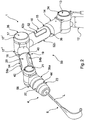
- FIG. 1 is a holding device 1, shown in the form of a holding arm.
- the holding device has a proximal end 2 for fastening the holding device 1 to a base 3.
- the base 3 is designed as a standard rail of an operating table (the operating table is shown in FIG Figure 1 Not shown).
- the holding device 1 also has a distal end 4 for receiving an attachment 6 (cf. Figure 2 ) on.
- the holding device according to Figures 1 and 2 has seven arm segments 10, 12, 14, 16, 18, 20, 22, with between the individual arm segments 10 to 22 the joints 11, 13, 15, 17, 19, 21, 23 are provided.
- the first arm segment 10 forms the proximal end 2 and has a clamping claw 24 by means of which the holding device 1 can be fixed on the base 3.
- a switch-on button 26 is also provided on the arm segment 10 for switching on the entire holding device, two connections 28a, 28b via which the holding device can be supplied with power and data, such as actuating signals and the like, and via which the data from the holding device to external units such as are transmitted to operating room systems, and an emergency stop switch 30.
- the joints 11, 15, 19 and 23 are designed as rotary joints and the joints 13, 17 and 21 as swivel joints. That is, based on Figure 1 , the axes of rotation of the joints 11, 15, 19 and 23 are essentially within the plane of the drawing, while the axes of rotation of the joints 13, 17 and 21 extend substantially perpendicular to the plane of the drawing.
- the holding device 1 has a display unit 32, 34, 36, 38, 40, 42, 44 on each joint 11, 13, 15, 17, 19, 21, 23, which are provided to show a status of the holding device and / or one Attachment (compare Figure 2 ).
- the display units 32, 34, 36, 38, 40, 42, 44 are designed as essentially ring-shaped light sources, in particular as LED rings.
- the central axis of each ring runs essentially coaxially to the respective axis of rotation of the joint 11, 13, 15, 17, 19, 21, 23. While a single LED ring is provided for each of the joints 11, 15, 19, 23, for the joints 13, 17 and 21 each provided two LED rings.
- the two LED rings are attached to front and rear hinge sections 17 ', 17 "(in Figure 2 provided only for example with reference numerals). In this way, every display unit is always recognizable in every position of the holding device.
- the holding device also has an operating device 50.
- the operating device 50 By means of the operating device 50, the holding arm can be brought into a desired pose, the operating device 50 being set up for this when there is contact between an operator and one of the seven arm segments 10, 12, 14, 16, 18, 20, 22 to release the associated joint 11, 13, 15, 17, 19, 21, 23.
- the operating device 28 has three contact sections 52, 54, 56, each contact section 52, 54, 56 being arranged on a different arm segment 16, 20, 22.
- a contact section 52 is arranged on the arm segment 16, a contact section 54 on the arm segment 20, and a contact section 56 on the arm segment 22.
- Each contact section 52, 54, 56 has separate contact elements 52a, 52b, 52c, 54a, 54b, 54c and 56a.
- the individual contact elements are designed as touch-sensitive surfaces, so that when there is contact between an operator and a corresponding contact means, one or more associated joints are released.
- three contact elements 52a, 52b, 52c, 54a, 54b, 54c are formed on each of the arm segments 16 and 20, an annular contact element 56 is arranged on the arm segment 22, which is also rotatable about its central axis, in order to provide functions to a To influence the interface at the distal end 4 recorded attachment.
- the assignment of the individual joints 11, 13, 15, 17, 19, 21, 23 is regulated according to this embodiment as follows: When there is contact between an operator and the arm segment 16, i.e. the contact elements 52a, 52b, 52c of the contact section 52, the joints 15, 13 and 11 released. An operator can now influence three degrees of freedom; this is an extent which can be easily controlled manually and in which the holding device can be brought into a desired pose manually. If an operator comes into contact with the arm segment 16 and the joints 15, 13 and 11 are released, it is preferably provided that the corresponding display units 32, 34, 36 indicate this release, according to the exemplary embodiment of FIG Figures 1 and 2 by lighting up the LED ring.
- the joints 19 and 17 are released. Accordingly, it is preferably provided that the display units 36, 38 indicate this. Finally, there is contact between the arm segment 22, that is to say the contact section 56 and in particular the contact element 56a, the joints 21 and 23 are released, which is preferably displayed by means of the display units 42, 44.
- an attachment 6 in the form of a retractor or retractor is received at the distal end 4.
- one or more force sensors are arranged, by means of which a tensile force acting in the direction of the longitudinal axis L can be determined. Furthermore, these sensors can preferably also be used to determine corresponding torques at the interface about the longitudinal axis L, as well as perpendicular to it.
- the display unit 44 is set up to display this status of the attachment 6, and in particular to display whether a certain force is within predetermined limits.
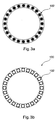
- FIGS. 3a to 7c show altogether different exemplary embodiments of display units according to the invention. All in the Figures 3a to 7c The display units shown are designed in a single row.
- Figure 3a shows a display unit 100 in a preferred embodiment of the invention.
- the display unit 100 is ring-shaped and has a plurality of LEDs 102 (in Figure 3a only one provided with reference numerals), which are arranged in a ring.
- the LEDs 102 are off according to the exemplary embodiment Figure 3a, 3b aligned within the plane of the drawing, so that the display unit according to this exemplary embodiment can be used as a display unit 34, 38 or 42, for example. While the display unit 100 in Figure 3a is shown in a first state, the same display unit 100 is in FIG Figure 3b shown in a second state. It should be understood that the two states are in an off state, for example Figure 3a and an on state in Figure 3b could be. Alternatively, it is also conceivable that Figure 3a shows that the display unit 100 lights up in a first color while in FIG Figure 3b lights up in a second different color.
- the display unit 100 is according to FIG Figures 3a, 3b with an internal control of the holding device 1 (cf. Figures 1 , 2 ) connected. It is preferred here that the display device 100 lights up in a first color when a contact between the operator and one of the contact elements 52a, 52b, 52c, 54a, 54b, 54c, 56a is detected. It is preferably provided here that the corresponding joint is not released immediately upon contact, but that this takes place with a time delay, for example after two seconds.
- the display unit does not display the release or locking of a joint, but rather the actuation of the operating device, so that an operator still has sufficient time to abort or confirm his action until the joint is actually released. It can also be provided that when all joints are released, only one display unit 100 lights up.
- the arm segment 10 (see Figure 1 ) an additional display unit is provided which is not assigned to any joint. This indicates that all joints in the holding device are released. In such a case, it is conceivable that the individual display units 32, 34, 36, 38, 40, 42, 44 assigned to the joints do not separately display the release of the joints.
- the display units 100 are coupled to a signal line of the brakes in the joints.
- a display unit 100 lights up when a voltage is applied to the brake in order to open it.
- the display unit 100 is coupled to a bus system of the brakes, so that the display units pick up the control signal for the brake and light up based on this control signal, and thus indicate that the brake has received an actuating signal to be released.
- a display unit 100 switches between two or more different colors (in particular switches completely, i.e. all LEDs 102 have the same color), is preferably also used to display a status of the holding device that differs from releasing and locking the corresponding joint or the attachment. It is also preferred that, depending on the application in which the holding device is used, the display units 100 light up in a color provided for this purpose. If the holding device is used, for example, in an ENT operation, all display units are green (preferably when the brakes are locked). If the same holding device is used in an abdominal surgery operation, all display units (preferably when the brakes are locked) are blue.
- a surgeon is able to immediately recognize whether the holding device is correctly set for the present application or is correctly supplied with data from an operating room system.
- This can be advantageous if the different applications, for example, require different braking behavior of the brakes in the joints, different forces can act on the holding device, or only a certain number and group of attachments is permitted.
- corresponding data are transferred and / or queried via interfaces, preferably a distal and a proximal end of the holding device 1, and processed in an internal controller, which then sends a corresponding signal to the display units 100.
- the display unit 100 is according to FIG Figures 3a, 3b with one or more position sensors in the joints, preferably the respective display unit coupled to a position sensor in the respective joint.
- the status which differs from locking and / or releasing, is in such an embodiment the status of the movement of a joint. That is, an operator can first release one or more joints by means of the operating unit 50; this is then not indicated by the display unit (N). Only when the operator moves a joint does the corresponding display unit light up on. It is thus conceivable that the operator grips the arm segment 20 (cf. Figure 1 ) and thereby comes into contact with the contact section 54. Both the joint 19 and 17 and 15 are released. If the operator then only pivots the joint 17, only the display unit 38 lights up. This gives an operator feedback as to which joint is currently being moved and can thus check his action.
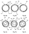
- FIGS. 5a to 5c show a display unit 100 as they are basically from FIGS Figures 3a, 3b is known in a second embodiment.
- display units are shown that can not only switch between two or more different colors overall, but in which individual LEDs 102, 103, 104, 106 can assume different colors (cf. Figures 4a to 4c ) or the intensity of the lighting is changed (cf. Figures 5a to 5c ). This is particularly advantageous when the holding device is positioned and the operator is to receive feedback on this positioning.
- a display unit 100 as in FIGS Figures 5a to 5c shown, then lights up when a joint is moved, that is to say when, for example, joint 17 is moved, the display unit 38 lights up.
- the light intensity can then be varied depending on the speed of movement.
- Figure 5a shows in such a case a display unit 100, which indicates that there is no movement
- Figure 5b illustrates a medium speed movement
- Figure 5c a movement at high speed.
- Position sensors in the joints of the holding device 1 are preferably also used for measuring, in particular measuring a movement. It is thus possible to determine, for example, a distance between two points, for example tissue sections of a patient, by appropriate actuation of the holding device 1 and movement of the holding device 1. If the holding device which is designed in this way is placed in a corresponding mode for measuring, it is preferred that the display units indicate this. This is for example in the Figures 4a to 4c shown. The Figures 4a to 4c also illustrate a function in which an operator transfers the holding device from a current pose to a desired pose and the displayed one In such a case, status is the distance to the desired pose.
- the Figures 6a to 6c illustrate another possibility for the display unit to display a measuring function or a measuring mode.
- the display unit 100 in the form of an LED ring, has four different sections 110, 112, 114, 116, which have two different colors, in each case alternately.
- the individual LEDs 102 are then controlled by an internal controller in such a way that the pattern with the four sections 110, 112, 114, 116 with reference to the Figures 6a to 6c rotates to the right and so the individual sections 110, 112, 114, 116 "wander" with the movement of the corresponding arm segment. If, for example, joint 17 is released and the section of the holding device between the joint 17 and the distal end 4 is pivoted, the individual sections 110, 112, 114, 116 move in the direction of the pivoting movement at the appropriate speed in order to display the status of the movement and to support the operator in recognizing how quickly and over what angle the holding device section is pivoted.
- FIG. 7a to 7c A similar illustration is in the Figures 7a to 7c in which the display device 100, which is designed as an LED ring, has two sections 118, 120. These each have a color gradient from an LED 122, 124, which lights up in a first color, to an LED 126, 128, which lights up in a second Color glows.
- the arrows 130, 140 indicate a direction of rotation of the pattern.
- FIGS Figures 3a, 3b shown Further embodiments of a visualization by means of a display unit 100 are that the display unit 100 lights up in a first color as long as the arm does not vibrate or vibrates in a defined, stored tolerance field. The first color remains displayed until the arm stops swinging. This is preferred when very fine manipulators are added to the holding device as attachments. This informs an operator to wait until the holding device is within a tolerance range that is acceptable. If the holding device swings, then if possible an attachment should not be moved any further. Furthermore, the position sensors in the joints can be used to detect when the holding device is hit or a joint is pivoted in the locked state against the force of the brake.
- This can be detected by means of position and / or position sensors and can be displayed by means of the display units. In this way, an operator receives feedback as to whether the holding device is still in the desired pose or whether, for example, a joint has been moved against the force of the brake.
- a display unit as in the Figures 6a to 7c shown is preferably also used to transfer a teaching, a sequence of poses (trajectory) to the holding device. It can be advantageous in advance of an operation or the like to perform different poses on the holding device and to store and / or test these. For this purpose, it is possible and preferred to put the holding device in a "teach mode" in which the poses that have been moved are recorded and stored by the internal control.
- the display units indicate this status, in particular with a pattern, as in FIG Figures 7a to 7c shown.
- the Figures 8a to 9b illustrate a display unit 200 according to a further exemplary embodiment, which is designed as a two-row LED ring.
- the display unit 200 (cf. Figure 8a ) has a first LED ring 202 and a second LED ring 204.
- a plurality of LEDs 206, 208 are arranged in each LED ring 202, 204.
- each LED ring 202, 204 does not have to be formed exclusively on a row of LEDs, but that this too can in turn be multi-row, the rows then preferably being controlled in the same way.
- embodiments with three or more LED rings are preferred.
- FIG. 8a, 8b For example, a rotating pattern is shown to be displayed on the LED ring 202, 204, for example as shown with reference to FIG Figures 6a to 7c has been described.
- the arrows 210, 212 point in FIG Figures 8a, 8b indicate a direction of rotation on the outer LED ring 202, while the arrows 214, 216 illustrate the direction of rotation of the pattern on the inner LED ring 204. While in Figure 8a it is shown that the pattern is moved in opposite directions (the arrows 210, 212 and 214, 216 are arranged in opposite directions) Figure 8b , a directional rotation.
- Such an advertisement ( Figure 8a ) is preferred, for example, when two joints are released and they are moved in opposite directions, or are to be moved in order to achieve a target pose. With a simultaneous display ( Figure 8b ) this can be used to indicate that movement in the same direction is required.
- FIGS. 9a, 9b illustrate movement of a pattern radially inward outward as indicated by arrows 218. Such an effect is increased if three or more LED rings are provided.
- Such a visualization is particularly preferably used to display a software update of software modules of one or more joints or of a central control unit.
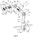
- Figure 10 illustrates a further embodiment of the holding device 1. This corresponds in a number of features with the holding device 1 according to FIG Figures 1 and 2 so that identical and similar elements have the same reference numerals as in FIGS Figures 1 and 2 are designated. In this respect, the above description of the Figures 1 and 2 Referenced. In the following, the differences between the exemplary embodiments according to FIGS Figures 1 and 2 as well as 10, 11 and 12 were received.
- the holding arm 1 is essentially like the holding arm 1 according to FIG Figure 1 and 2 constructed, but display units 250, 252, 254 are arranged on the three articulated joints 13, 17, 21, each of which has two displays 260, 261, 262, 263, 264, 265.
- the displays 260, 262, 264 can be seen, the displays 261, 263, 265 are based on FIG Figure 10 arranged on the rear side of the holding device 1 parallel to the displays 260, 262, 264.
- the displays 260, 261, 262, 263, 264, 265 are round and arranged with their central axis coaxially to the pivot axis of the corresponding joint 213, 217, 221.
- the displays 260, 262 show a period of time that the joint 13, 17 in question is already in this position. This is particularly helpful when a certain movement sequence is planned.
- the display 264 shows according to Figure 10 indicates an angular range in which the arm segment 22 is inclined. This gives an operator feedback about the alignment of the last arm segment on which the attachment is being picked up.
- the displays 260, 262, 264 indicate in which direction and by how many degrees a corresponding joint 13, 17, 21 may be pivoted in order not to pivot out of a working area of the holding device 1.
- the display 264 shows not only the direction of rotation of the joint 21 but also that of the joint 19, which is indicated by the horizontal arrow on the display 264.
- a corresponding visualization is also possible with the displays 262, 260, but not shown in this exemplary embodiment.
- a further visualization of a status of the holding device 1 is shown.
- the displays 260, 262, 264 show the weight on the individual joints 13, 17, 21 so that an operator can estimate whether the load on the holding device 1 is still in an acceptable range, and also whether under certain circumstances there is too much load on an attachment.
- displays 260, 261, 262, 263, 264, 265 are used as display units, further displays of a status or the like are conceivable here.
- the individual displays are preferably designed as touch-sensitive displays and are also used to input profiles to the holding device 1. For example, it is preferred that an on / off switch is displayed on the display 260, 261, and by touching the display 260 , 261 the holding device can be switched on or off. It is also conceivable that a current pose of the holding device 1 is stored by touching a display 260, 261, 262, 263, 264, 265.
- Other displays include the transmission of data transfer, displays of patient data, patient images such as X-ray images, CT / MR images, planning steps, access to a robot control of an attachment, and input of commands for the built-in device, displays of a work environment, for example connection to other systems and the like .
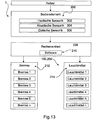
- the Figures 13 and 14th illustrate a basic structure of the system, comprising a holding device 1 and a user.
- the holding device 1 comprises operating elements 300, which can comprise haptic sensors 302, acoustic sensors 304 and optical sensors 306.
- a haptic sensor system is, for example, the operating device 50, as described above.
- the holding device 1 has a computing unit 308 which has a software module 310.
- Brakes 312 are arranged in joints, which are closed in a rest state and are opened when a voltage is applied.
- the holding device is designed as a so-called passive holding device and all joints are locked in the currentless state.
- lighting means 314 are provided as display units, each of which is assigned to a joint or a brake.
- a lamp 1 is assigned to brake 1, lamp 2 to brake 2, etc.
- the individual illuminants are preferably as in Figures 1 to 7c shown, trained.
- the computing unit is coupled to the operating elements and evaluates the operation, that is to say in particular the detected haptic, acoustic or optical signals. These are evaluated by means of the software module 310 and corresponding brakes 312 are released and / or locked. The release and / or locking is then displayed with the corresponding illuminant 314.
- the holding device 1 is only able to indicate the release and locking of individual joints, but not a status different therefrom.
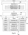
- the display units are designed to display a status different from releasing and locking, as in FIG Figure 14 is shown.
- the holding arm 1 which is basically structured in the Figure 13 equals, an additional sensor system 320.
- the sensor system 320 includes, for example, one or more position sensors 322, preferably in each joint, one or more acceleration sensors 324, preferably in each joint, one or more force sensors 326, preferably at least at the distal end 4 of the holding device 1, one or more torque sensors 328, preferably in each joint as well as at the distal 4 and proximal end 2 of the holding device 1, at least one bump sensor 330 and at least one temperature sensor 332.
- the software 310 is set up to determine a status and the display units 100 to cause this status to be displayed, in particular by means of the lighting means 314.
Description
- Die Erfindung betrifft eine Haltevorrichtung, insbesondere Haltearm und/oder Stativ, für medizinische Zwecke, insbesondere zum Halten von chirurgischen mechatronischen Assistenzsystemen und/oder chirurgischen Instrumenten. Weiterhin betrifft die Erfindung ein Verfahren.
- Haltearme, die unter Haltevorrichtungen der eingangs genannten Art fallen, sind bereits seit längerem bekannt und werden in der Chirurgie insbesondere dazu eingesetzt, einen Operateur von statischer Haltearbeit zu entlasten. Ein derartiger Haltearm wird eingesetzt, um ein mechatronisches Assistenzsystem und/oder ein chirurgisches Instrument zu halten, wie etwa ein Manipulator, ein Endoskop, eine chirurgische Klemme und dergleichen. Insbesondere zum Halten von Endoskopen haben sich die eingangs genannten Haltearme bewährt. Bei der endoskopischen Chirurgie bedient ein Operateur in der Regel mit beiden Händen ein Instrument, während ein Assistent das Endoskop hält, um das Operationsfeld über einen Bildschirm sichtbar zu machen. Das Halten des Endoskops über einen längeren Zeitraum ist sehr ermüdend. Aus diesem Grund werden vermehrt vorgenannte Haltearme eingesetzt.
- Ein solcher Haltearm ist beispielsweise aus
DE 195 26 915 B4 bekannt. Die dort offenbarte Haltevorrichtung für medizinische Zwecke weist ein Anschlussteil und einen Halter für chirurgische Werkzeuge sowie einen zwischen dem Halter und dem Anschlussteil angeordneten Arm auf. Der Arm ist mit dem Halter und dem Anschlussteil oder mit einem benachbarten Arm über ein Gelenk verbunden und mit einer pneumatisch betätigbaren Vorrichtung zur wahlweisen Festlegung und Lösung der Gelenke überkoppelt, wobei diese Vorrichtung die Gelenke unter Einwirkung einer Bremskraft auf das Gelenk ausübenden mechanischen Feder festlegt und wobei die Vorrichtung gegen die Kraft dieser Feder pneumatisch in einen das Gelenk freigebenden Zustand überführbar ist. An dem proximalen Ende des Arms ist ein Betätigungsorgan angeordnet, mittels dessen Hilfe ein Ventil öffenbar ist, sodass die einzelnen Gelenke des Arms verstellt werden können. Bei Loslassen des Betätigungsorgans wird das Ventil wieder geschlossen, sodass die Gelenke festgelegt sind. Nachteilig ist, dass mit dem Haltearm alle Gelenke gleichzeitig geöffnet werden, wodurch eine Positionierung schwierig sein kann. - Ein ähnlicher Haltearm ist in
EP 1 958 587 B1 offenbart. Der dort offenbarte Haltearm weist ebenfalls mehrere Gelenke auf, und zur Betätigung der Gelenke ist ein berührungssensitiver Sensor vorgesehen. Der Sensor ist am Haltearm benachbart zum medizinischen Instrument angeordnet, sodass bei Ergreifen des medizinischen Instruments der Operator in Kontakt kommt mit dem berührungssensitiven Sensor, wodurch alle Gelenke des Haltearms freigegeben werden. Auch hier tritt das oben genannte Problem der mangelhaften Positionierung auf. -
DE 10 2011 004 371 A1 offenbart einen Haltearm zur Halterung von chirurgischen Instrumenten. Dieser umfasst mindestens ein steuerbares Gelenk, das in einen beweglichen Zustand und in einen arretierten Zustand schaltbar ist. Eine steuerbare Klemmvorrichtung ist in einen geöffneten Zustand und in einen geklemmten Zustand schaltbar um ein chirurgisches Instrument zu greifen. Mittels einer Steuereinheit können Fernsteuerbefehle empfangen und diese in Schaltvorgänge des Gelenks und/oder der Klemmvorrichtung umgesetzt werden. In einer Anordnung mit einem Operationstisch ist vorzugsweise eine Fernbedieneinheit umfasst. - Weiterhin besteht bei beiden oben genannten Haltearmen das Problem, dass der Bediener darüber im Unklaren ist, ob tatsächlich alle Gelenke geöffnet sind, wie weit diese geöffnet sind, und welche Bewegungen zulässig sind.
- Aus
EP 2 455 053 B1 ist ferner ein Tragesystem zum Tragen bzw. zum Stützen medizintechnischer Geräte in einem Behandlungsraum bekannt. Das Tragesystem weist ein Stativ zum Montieren im Behandlungsraum, mindestens ein Gelenk bzw. mindestens einen Mechanismus, mit dem das Stativ im Behandlungsraum bewegbar ist, eine Bedienungshilfe zur Betätigung mindestens eines Teils des Tragesystems, um eine Bewegung des Stativs zu steuern und ein Rückmeldesystem zur Erzeugung eines Signals bzw. einer Rückmeldung über eine Betätigung des korrelierenden Teils des Tragesystems mit der Bedienungshilfe auf. Das Tragesystem zeichnet sich dadurch aus, dass das Rückmeldesystem mindestens einen Leuchtkörper aufweist, der den Teil des Tragesystems bzw. das entsprechende Gelenk oder den entsprechenden Mechanismus örtlich am Stativ an der jeweiligen Stelle des Mechanismus bzw. am entsprechenden Gelenk identifiziert bzw. kennzeichnet, typischerweise durch Beleuchtung. In dem gezeigten Ausführungsbeispiel umfasst das Tragesystem zwei Arme, die um parallel zueinander angeordnete Schwenkachsen verschwenkbar sind. An jedem Gelenk ist ein kurzes zylindrisches Stück vorgesehen, und in diesem zylindrischen Stück ist eine oval förmige Lampe angeordnet. Die Bedieneinheit ist als Fernbedienung ausgebildet und weist Tasten auf zum Freigeben jedes Gelenks. Die entsprechende Lampe an dem entsprechenden Gelenk leuchtet dann auf, wenn die Taste gedrückt ist. Dadurch soll es insbesondere in dunklen OP-Räumen einfacher sein, die richtige Taste zu drücken und so das richtige Gelenk freizugeben bzw. hierüber Feedback zu erhalten. - Nachteilig ist hieran, dass allein dann eine Lampe aufleuchtet, wenn der entsprechende Knopf an der Fernbedienung gedrückt ist, also das Gelenk betätigt ist.
- Schließlich offenbart
EP 0 855 002 A1 einen Haltearm, bei dem Kräfte oder Momente, die sich aus einer Unbalance ergeben gemessen werden, um eine gezielte Verstellung von Ausgleichsgewichten vornehmen zu können. - Aufgabe der vorliegenden Erfindung ist es daher, die Sicherheit der Bedienung einer derartigen Haltevorrichtung, sowie deren Bedienfreundlichkeit zu verbessern.
- Die Erfindung löst die Aufgabe bei einer Haltevorrichtung der eingangs genannten Art mit einem proximalen Ende zum Befestigen der Haltevorrichtung an einer Basis und einem distalen Ende zum Aufnehmen eines Anbaugeräts, wenigstens einem ersten und einem zweiten Armsegment, wobei das erste Armsegment mit einem ersten Gelenk und das zweite Armsegment mit einem zweiten Gelenk verbunden ist, wobei jedes Gelenk freigebbar und arretierbar ist, einer Bedieneinrichtung zum Freigeben und/oder Arretieren des entsprechenden Gelenks zum Verbringen der Haltevorrichtung in eine gewünschte Pose, und einer ersten Anzeigeeinheit, die an dem ersten Gelenk angeordnet ist und einer zweiten
- Anzeigeeinheit, die an dem zweiten Gelenk angeordnet ist, wobei die erste und/oder zweite Anzeigeeinheit dazu eingerichtet sind, wenigstens einen vom Freigeben und Arretieren des entsprechenden Gelenks verschiedenen Status der Haltevorrichtung und/oder eines Anbaugeräts anzuzeigen. Das Anzeigen erfolgt bevorzugt mittels Anzeigen einer den Status repräsentierenden Repräsentation. Der Erfindung liegt die Erkenntnis zugrunde, dass allein das Anzeigen des Freigebens oder Arretierens eines entsprechenden Gelenks, also der Betätigung, unter Umständen nicht ausreicht, um eine ausreichende Sicherheit und/oder Bedienfreundlichkeit zu erreichen. Das Anzeigen des wenigstens einen vom Freigeben und Arretieren des entsprechenden Gelenks verschiedenen Status der Haltevorrichtung und/oder eines Anbaugeräts kann dabei zusätzlich oder alternativ zum Anzeigen des freigegebenen oder arretierten Status der Haltevorrichtung erfolgen. Die Anzeige stellt dem Bediener dadurch weitere, über den reinen Status des Freigebens und Arretierens eines Gelenks hinausgehende Kennzeichnungen bereit, durch die die Bedienfreundlichkeit bzw. Sicherheit dann erhöht ist. Die Anzeigeeinheit kann elektrisch, mechanisch oder elektronisch ausgebildet sein und mittels visuellen und/oder akustischen Anzeigen arbeiten.
- Gemäß einer ersten bevorzugten Ausführungsform weisen die Anzeigeeinheiten jeweils wenigstens eine Lichtquelle auf. In einer solchen Ausführungsform ist die den Status repräsentierende Repräsentation das Aufleuchten der Lichtquelle(n). Dies ist eine besonders einfache Art, die Anzeigeeinheiten auszubilden. Ferner ist diese visuell erfassbare Anzeigeeinheit auch bei schlechten Sichtverhältnissen erfassbar. Vorzugsweise ist die Lichtquelle dazu eingerichtet, in zwei oder mehr verschiedenen Farben aufzuleuchten und dadurch kann verschiedenen Status eine verschiedene Farbe zugeordnet werden, wodurch weiterhin Sicherheit und Bedienfreundlichkeit verbessert sind.
- In einer bevorzugten Weiterbildung weisen die Anzeigeeinheiten wenigstens ein Display zum Anzeigen des Status auf. Bevorzugt weist wenigstens eine der Anzeigeeinheiten ein derartiges Display auf. Besonders bevorzugt weist jede der Anzeigeeinheiten ein Display zum Anzeigen des Status auf. Ein solches Display kann beispielsweise als berührungsempfindliches Display ausgebildet sein und zeigt bevorzugt sowohl graphische, als auch alphanummerische Wiedergaben an. So ist es denkbar bevorzugt, dass beispielsweise Patientendaten, wie Alter, Gewicht, Erkrankungen und dergleichen angezeigt werden, als auch Daten aus einer Operation, wie beispielsweise Körperfunktionsdaten oder Anästhesiedaten. Auch ist es denkbar in einem solchen Fall, dass die Anzeigeeinheiten nicht ausschließlich dazu dienen, den Status der Haltevorrichtung anzuzeigen, sondern auch einen Status eines Patienten und/oder einer Umgebung, oder zum Anzeigen von Informationen.
- Gemäß einer weiteren bevorzugten Ausführungsform ist wenigstens eine Anzeigeeinheit im Wesentlichen ringförmig um eine Schwenkachse des entsprechenden Gelenks ausgebildet. Beispielsweise ist die Anzeigeeinheit als ringförmige Lichtquelle, beispielsweise ein Ring aus LED-Elementen, als ringförmiges OLED, als ringförmiges Display oder dergleichen ausgebildet. Ein LED-Ring kann dabei beispielsweise einreihig oder zwei- oder mehrreihig ausgebildet sein. Bevorzugt ist die im Wesentlichen ringförmige Anzeigeeinheit koaxial zur Schwenkachse des entsprechenden Gelenks ausgebildet. Dadurch ist die Anzeigeeinheit von jeder Seite der Schwenkachse aus sichtbar und gleichzeitig ein Indikator für den Verlauf der Schwenkachse. Bevorzugt sind wenigstens zwei derartige Anzeigeeinheiten an einem Gelenk angeordnet und zwar so, dass sie beide koaxial zur Schwenkachse angeordnet sind.
- Gemäß einer bevorzugten Weiterbildung ist der Status ein Betriebsbereitheits-Status der Haltevorrichtung. Beispielsweise ist die Anzeigeeinheit dazu eingerichtet, in einer ersten Farbe zu leuchten, wenn die Haltevorrichtung betriebsbereit ist, und in einer zweiten Farbe zu leuchten, wenn sie nicht betriebsbereit ist. Vorzugsweise leuchten alle Anzeigevorrichtungen gleichzeitig und/oder blinken auf, um dies anzuzeigen. So ist es denkbar und bevorzugt, dass nach einem Einschalten der Haltevorrichtung, zunächst ein interner Mikroprozessor die Betriebsbereitheit überprüft, und in Abhängigkeit davon der Betriebsbereitheits-Status mittels der Anzeigeeinheiten angezeigt wird. Hierdurch kann ein Bediener sofort erkennen, ob die Haltevorrichtung betriebsbereit ist und beispielsweise in einer chirurgischen Operation eingesetzt werden kann, oder ob ein Defekt oder dergleichen vorliegt.
- In einer weiteren bevorzugten Ausführungsform ist der Status ein Abstand zwischen einem Anbaugerät und einem Rand eines vordefinierten Arbeitsbereichs der Haltevorrichtung. Durch Lagesensoren in den Gelenken oder dergleichen kann eine Lage der Haltevorrichtung bestimmt werden, und so ein Abstand zwischen einem Anbaugerät, welches an der Haltevorrichtung aufgenommen ist, oder im Abschnitt der Haltevorrichtung selbst, und einem Rand eines vordefinierten Arbeitsbereichs, bestimmt werden. Bevorzugt ist vorgesehen, dass die Anzeigevorrichtungen den Abstand visuell anzeigen. Beispielsweise ist bevorzugt, dass die Anzeigevorrichtungen ihre Leuchtintensität ändern, beispielsweise erhöhen, um den Abstand anzuzeigen, von einer ersten in eine zweite Farbe wechseln, und/oder einen Warnton ausgeben. Beispielsweise kann vorgesehen sein, dass die Anzeigevorrichtungen diskret in zwei Farben leuchten, und der Anteil der einen Farbe reduziert wird, wenn die Haltevorrichtung auf den Rand zu bewegt wird.
- Bevorzugt ist ferner vorgesehen, dass der Status ein Abstand zwischen einer aktuellen Pose der Haltevorrichtung und einer vordefinierten Pose der Haltevorrichtung ist. Hierdurch wird ein Operateur dabei unterstützt, den Haltearm in die korrekte Pose zu bewegen. Beispielsweise kann vorgesehen sein, dass einige oder alle Anzeigevorrichtungen orange leuchten, wenn die Pose noch nicht erreicht ist, und nach und nach in eine grüne Farbe wechseln, wenn das entsprechende Gelenk die entsprechende vordefinierte Pose erreicht hat. Hierdurch ist sowohl die Sicherheit als auch die Bedienfreundlichkeit wesentlich verbessert, und ein Operateur erhält unmittelbar und direkt Feedback darüber, ob die Haltevorrichtung in der korrekten Pose ist.
- Dabei, oder bei einer anderen Ausführungsform, kann zusätzlich vorgesehen sein, dass die Anzeigeeinheiten dazu eingerichtet sind, eine Richtung anzuzeigen, in die wenigstens ein Gelenk zu bewegen ist, um die Haltevorrichtung von der aktuellen Pose in die vordefinierte Pose zu bewegen. Dies erfolgt vorzugsweise mittels Blinken, Rotieren eines Musters, Variation der Helligkeit, Variation der Farbe. Vorzugsweise werden einige oder alle Gelenke bei Erreichen der vordefinierten Pose automatisch arretiert. Eine derartige vordefinierte Pose kann beispielsweise über ein OP-System oder über eine OP-Planungssoftware erhalten werden.
- In einer weiteren bevorzugten Ausführungsform ist der Status ein Arbeitsstatus einer Steuerung der Haltevorrichtung. Die Haltevorrichtung weist bevorzugt eine Steuerung, beispielsweise einen Mikrocontroller oder dergleichen auf. In einem Arbeitsstatus führt eine Steuerung beispielsweise die folgenden Aufgaben aus: Abspeichern der aktuellen Pose, Berechnen einer Pose, Abrufen von vorgespeicherten Posen, Schreiben von OP-Protokollen, Aufnehmen/Verarbeiten von mittels des Anbaugeräts erfassten Daten, Aufspielen von Software auf Mikrocontroller in Gelenken, Anzeigen einer Progress-Bar beim Arbeiten bzw. Verarbeiten von Daten, und dergleichen. Hierdurch erhält ein Bediener unmittelbar Feedback darüber, in welchem Status die Haltevorrichtung ist, beispielsweise ob die aktuell eingenommene Pose abgespeichert wird oder dergleichen. Der Bediener kann auch erkennen, ob Daten, die mittels des Anbaugeräts aufgenommen oder verarbeitet werden, gespeichert und/oder verarbeitet werden.
- Gemäß einer weiteren Ausführungsform ist der Status ein Kommunikationsstatus der Haltevorrichtung mit dem Anbaugerät. Das heißt, die Anzeigeeinheiten zeigen an, ob und vorzugsweise wie, welche Intensität, Datenmenge oder dergleichen, die Haltevorrichtung mit dem Anbaugerät kommuniziert. Werden beispielsweise Daten von dem Anbaugerät an die Haltevorrichtung, insbesondere eine dafür vorgesehene Schnittstelle am distalen Ende, übertragen, so wird dies mittels der Anzeigeeinrichtung angezeigt. Dies kann beispielsweise durch Beleuchten wenigstens einer Anzeigeeinrichtung in einer vordefinierten Farbe erfolgen.
- Weiterhin ist bevorzugt, dass der Status eine Bewegung der Haltevorrichtung ist. Bevorzugt ist demnach vorgesehen, dass die Anzeigevorrichtung anzeigt, wenn ein Gelenk bewegt wird. Gemäß dieser Ausführungsform ist beispielsweise vorgesehen, dass zunächst mittels einer Bedieneinheit ein Gelenk freigegeben wird, die Anzeigeeinheit aber nicht, bzw. nicht nur, das Freigeben anzeigt, sondern das tatsächliche Bewegen des Gelenks. Dazu weist der Haltearm vorzugsweise Lagesensoren in wenigstens einem, vorzugsweise allen, Gelenken auf.
- Wenn der Status eine Bewegung ist, umfasst dies auch in einer bevorzugten Ausführungsform, dass die Anzeigevorrichtungen anzeigen, wenn die Haltevorrichtung insgesamt, insbesondere ohne Veränderung der Pose, bewegt wird. Dies ist beispielsweise dann der Fall, wenn die Haltevorrichtung mittels des proximalen Endes an einem OP-Tisch befestigt ist, und dieser bewegt, das heißt verschoben, verschwenkt, gedreht oder dergleichen, wird. In einem solchen Fall wird die Bewegung des Haltearms bevorzugt durch wenigstens eine Anzeigeeinheit angezeigt, beispielsweise durch Aufleuchten, Blinken, Ändern der Farbe, ein akustisches Signal oder dergleichen. Eine Veränderung der Position des OPTisches kann bedeuten, dass auch auf diesem angeordnete Gegenstände, oder auch der Patient, die Lage ändern, wodurch sich eine relative Lage der Haltevorrichtung zum Patienten ändern kann, wodurch wiederum Gefahren hervorgerufen werden können. Daher wird auch in dieser Ausführungsform die Sicherheit wesentlich verbessert.
- Weiterhin umfasst der Status der Bewegung bevorzugt, eine Bewegung eines Gelenks im arretierten Zustand. Wird die Haltevorrichtung stark belastet, kann es vorkommen, dass einzelne Bremsen in Gelenken "durchrutschen", und sich ein Gelenk bewegt, obwohl es arretiert ist. Gemäß dieser Ausführungsform ist vorgesehen, dass eine derartige Bewegung durch insbesondere einen Lagesensor erfasst wird und die entsprechenden Anzeigeeinheiten diese Bewegung anzeigen. Dies erfolgt wiederum bevorzugt durch Aufleuchten, Ändern der Intensität des Aufleuchtens, Ändern der Farbe, Blinken, Ändern der Frequenz des Blinkens, ein Signalton oder dergleichen.
- In einer weiteren bevorzugten Ausführungsform weist die Haltevorrichtung eine Messeinrichtung, zum Messen wenigstens eines physikalischen und/oder chemischen Werts auf, und der Status ist der gemessene Wert. Beispielsweise weist die Haltevorrichtung einen Kraftsensor auf, und an dem Anbaugerät, und/oder am distalen Ende der Haltevorrichtung greift eine Kraft an, beispielsweise aufgrund eines Kontakts zwischen Haltevorrichtung und einem Patienten, und der Status ist die gemessene Kraft. Ebenso könnte es beispielsweise der pH-Wert sein. Bevorzugt zeigt die Anzeigevorrichtung an, ob der gemessene Wert innerhalb vorbestimmter Grenzwerte liegt. Hierzu kann beispielsweise ein Zwei-Farben-Code, beispielsweise Rot-Grün verwendet werden. Zeigt die Anzeigeeinheit Rot an, ist dies gemäß einer Ausführungsform ein Indikator dafür, dass ein gemessener Wert, beispielsweise eine gemessene Kraft, außerhalb der vorbestimmten Grenzen liegt. Der Operateur sollte in einem solchen Fall die Pose der Haltevorrichtung anpassen, um so eine Pose zu erreichen, in der die Kraft in dem vorbestimmten Bereich liegt.
- An dem distalen Ende der Haltevorrichtung, insbesondere an der Schnittstelle, sind bevorzugt mehrere Kraftsensoren angeordnet, um so eine Messeinrichtung zum Messen wenigstens eines physikalischen Werts zu bilden. Die mehreren Kraftsensoren sind bevorzugt so angeordnet, dass auch eine Momentenaufnahme an dem distalen Ende der Haltevorrichtung, insbesondere an einer Schnittstelle, gemessen werden kann. Alternativ kann auch ein einzelner Kraft-Momenten-Sensor dort vorgesehen sein. Dies ist besonders dann vorteilhaft, wenn am distalen Ende beispielsweise ein Retraktor oder ein ähnliches Werkzeug aufgenommen ist, welches mit einer vorbestimmten Kraft oder einer Kraft in einem vorbestimmten Bereich auf den Patienten oder ein anderes Objekt einwirken soll. Ein Bediener kann durch Bewegen der Haltevorrichtung die Kraft exakt einstellen, diese wird mittels der Anzeigeeinheiten angezeigt, und der Bediener kann die Haltevorrichtung so bewegen, dass die Gelenke dann arretiert werden, wenn die Kraft in etwa den vorbestimmten Wert erreicht hat. So ist es beispielsweise möglich, mit einer vorbestimmten Kraft an einem Gewebeteil zu ziehen. Gleichzeitig weist die Haltevorrichtung vorzugsweise eine Zeitmesseinheit auf, die misst, für welche Zeitdauer dieselbe oder eine ähnliche Kraft anliegt. Beispielsweise kann es vorteilhaft sein, an bestimmten Gewebeabschnitten des Patienten nur für einen bestimmten Zeitabschnitt mit einer bestimmten Kraft einzuwirken, und anschließend die Höhe der Kraft sowie die Richtung der Kraft zu ändern. Auch dies kann einem Bediener mittels der Anzeigeeinheiten angezeigt werden. So ist es beispielsweise vorteilhaft, wenn neben der Kraft auch die Zeitdauer angezeigt wird. Dadurch können Verletzungen des Patienten vermieden werden. Ferner werden Assistenzpersonen bei einer Operation entlastet und müssen keine lang andauernde statische Haltekraft (Kraft mit bestimmter Höhe in bestimmter Richtung) leisten. Zusätzlich kann vorgesehen sein, dass, wenn ein Operateur die Haltevorrichtung so bewegt, dass sich die Kraft erhöht, ein oder mehrere Gelenke von einer internen Steuereinheit geschlossen werden, wenn eine Maximalkraft erreicht ist. So wird verhindert, dass mit einer zu großen Kraft auf den Patienten eingewirkt wird. Gleichzeitig ist bevorzugt, dass das automatische Arretieren der Gelenke mittels der Anzeigeeinheiten angezeigt wird, sodass der Operateur hierüber eine Rückmeldung erhält. Dies hilft, die Traumatisierung zu verhindern.
- Gemäß einer weiteren Ausführungsform sind die Anzeigevorrichtungen dazu eingerichtet, anzuzeigen, ob ein entsprechendes Gelenk freigegeben oder arretiert ist. Die Haltevorrichtung weist eine Bedieneinrichtung zum Freigegen und/oder Arretieren des entsprechenden Gelenks auf. Gemäß dieser Ausführungsform zeigen die Anzeigevorrichtungen zusätzlich an, ob ein entsprechendes Gelenk mittels der Bedieneinrichtung freigegeben oder arretiert ist.
- Erfindungsgemäß wird die eingangs genannte Aufgabe einer Haltevorrichtung der eingangs genannten Art gelöst durch eine Bedieneinrichtung, die dazu eingerichtet ist, bei Kontakt zwischen einer Bedienperson und einem der ersten und zweiten Armsegmente das zugeordnete Gelenk freizugeben. Gemäß einer weiteren Ausführungsform sind die Anzeigeeinheiten dazu eingerichtet, anzuzeigen, ob ein entsprechendes Gelenk freigegeben oder arretiert ist. Die Haltevorrichtung gemäß diesem Aspekt weist erfindungsgemäß eine Bedieneinrichtung auf, die dazu eingerichtet ist, bei Kontakt zwischen einer Bedienperson und einem der ersten und zweiten Armsegmente das zugeordnete Gelenk freizugeben.
- Gemäß dieser Ausführungsform ist daher vorgesehen, dass die Bedieneinrichtung dazu eingerichtet ist, bei Kontakt zwischen einer Bedienperson und dem ersten Armsegment, das erste Gelenk freizugeben und bei Kontakt zwischen einer Bedienperson und dem zweiten Armsegment, das zweite Gelenk freizugeben. Es ist also gemäß dieser Ausführungsform vorgesehen, dass bei Kontakt einer Bedienperson mit einem entsprechenden Armsegment nur das zugeordnete Gelenk freigegeben wird. Dieses Freigeben wird dann mittels den Anzeigeeinheiten angezeigt. Dadurch ist es möglich, intuitiv einzelne Gelenke zu bewegen und die Haltevorrichtung so segmentweise zu verstellen und in eine gewünschte Pose zu bringen. Dadurch ist eine genauere Positionierung möglich, da inkrementell jedes Segment separat verstellt werden kann. Es ist ebenso möglich, mehrere Segmente auch im Wesentlichen gleichzeitig zu kontaktieren, sodass mehrere Gelenke gleichzeitig freigegeben werden und dieses Freigeben gleichzeitig angezeigt wird, und die Gelenke verstellbar sind. Dadurch ist es möglich, die Haltevorrichtung auf einfache Art und Weise, insbesondere intuitiv, in eine gewünschte Pose zu überführen, wobei die Anzeigeeinheiten das Freigeben einzelner Gelenke anzeigen und der Bediener so ein unmittelbares und intuitives Feedback erhält.
- Neben den ersten und zweiten Armsegmenten sind vorzugsweise weitere Armsegmente vorgesehen, die ebenfalls jeweils einem Gelenk zugeordnet sind. Die Armsegmente selbst sind im Wesentlichen starr und vorzugsweise im Wesentlichen stabförmig. Der Begriff "stabförmig" umfasst hier sowohl im Wesentlichen gerade Armsegmente als auch leicht bis stark gekrümmte Armsegmente. Bei einer derartigen Haltevorrichtung wechseln sich Armsegmente und Gelenke stets ab, wobei die Haltevorrichtung am distalen und am proximalen Ende sowohl mit einem Gelenk als auch mit einem Segment oder einem Anschlusselement enden kann. Mit dem proximalen Ende ist die Haltevorrichtung an einer Basis befestigbar. Die Basis kann alternativ fest mit der Haltevorrichtung gekoppelt sein, oder die Haltevorrichtung ist von der Basis entnehmbar. Die Basis ist in einer Ausführungsform als Operationstisch ausgebildet, und die Haltevorrichtung ist mit einem Operationstisch koppelbar. Vorzugsweise ist die Haltevorrichtung mit einer an dem Operationstisch vorgesehenen Normschiene koppelbar. Derartige Normschienen sind in der Regel bei Operationstischen vorgesehen, sodass an der Haltevorrichtung zur Kopplung mit der Normschiene eines Operationstisches eine Standardschnittstelle vorgesehen sein kann. Übliche Operationstische sind zudem aus einzelnen Segmenten zusammengesetzt. Zur Kopplung weisen die Segmente an den Stirnseiten entsprechende Koppelstellen auf, die in der Regel herstellerspezifisch sind. Bevorzugt ist die Haltevorrichtung über eine solche Koppelstelle an dem Operationstisch befestigbar. Dazu kann an dem proximalen Ende ein herstellerspezifischer Adapter vorgesehen sein. Alternativ ist die Basis als eine separate Vorrichtung, wie etwa ein Ständer, der auf dem Boden eines Operationssaales aufstellbar ist. In einer weiteren Alternative ist die Basis als eine Halterung ausgebildet, die beispielsweise an einer Wand oder Decke eines Operationssaales befestigbar ist.
- Die Haltevorrichtung ist vorzugsweise als sogenannte passive Haltevorrichtung ausgebildet und weist daher ausschließlich aktiv gebremste Gelenke auf, jedoch keine angetriebenen Gelenke, wie dies bei robotischen Haltevorrichtungen häufig der Fall ist. Jedes Gelenk ist daher nur freigeb- und arretierbar, allerdings nicht antreibbar. Hierdurch ist die Haltevorrichtung einfach aufgebaut und bedarf keiner komplexen Steuerung zu ihrem Betrieb.
- Gemäß einer ersten bevorzugten Ausführungsform der Erfindung weist die Bedieneinrichtung Kontaktmittel auf, die dazu vorgesehen sind, dass ein Bediener mit diesen in Kontakt kommt, wobei ein erstes Kontaktmittel der Bedieneinrichtung an dem ersten Armsegment angeordnet ist und ein zweites Kontaktmittel an dem zweiten Armsegment angeordnet ist. Bei Kontakt mit dem ersten Kontaktmittel wird vorzugsweise das erste Gelenk freigegeben, und bei Kontakt mit dem zweiten Kontaktmittel wird vorzugsweise das zweite Gelenk freigegeben. Die Kontaktmittel dienen dazu, den Kontakt zwischen dem Benutzer und dem Armsegment zu erfassen. Die Kontaktmittel sind vorzugsweise jeweils an einer Oberfläche des entsprechenden Armsegments angeordnet. Die Kontaktmittel können sich über das gesamte Armsegment erstrecken oder nur einen Abschnitt von diesem einnehmen. Vorzugsweise erstreckt sich das Kontaktmittel jeweils in etwa um einen halben Umfang bezogen auf eine Zentralachse eines Armsegments. Dadurch ist das Kontaktmittel in jeder Pose der Haltevorrichtung leicht zugänglich, und ein Bediener kann leicht mit diesem in Kontakt kommen.
- Gemäß einer weiteren bevorzugten Ausführungsform weist jeder Kontaktabschnitt zwei, drei oder mehr an dem Armsegment im Wesentlichen gegenüberliegend bzw. gleichmäßig verteilt angeordnete Kontaktelemente auf. Gemäß diesem Ausführungsbeispiel ist es bevorzugt, dass das zugeordnete Gelenk nur bei Kontakt von den beiden bzw. zwei von drei oder mehr, oder allen Kontaktelementen freigegeben wird. Der Kontaktabschnitt besteht vorzugsweise aus den zwei, drei oder mehr Kontaktelementen, sodass ein Kontakt mit dem Kontaktabschnitt nur dann vorliegt, wenn wenigstens zwei Kontaktelemente von dem Bediener kontaktiert werden. Indem die beiden Kontaktelemente im Wesentlichen gegenüberliegend, vorzugsweise bezogen auf eine Ebene, die eine Zentralachse des Armsegments enthält, angeordnet sind, ist es möglich, einen unbeabsichtigten Kontakt, beispielsweise durch den Arm eines Bedieners von einem beabsichtigten Kontakt, einem konkreten Greifen des Armsegments zu unterscheiden; folglich wird gemäß diesem Ausführungsbeispiel das Gelenk nur bei einem Ergreifen des Armsegments, insbesondere durch die Hand des Bedieners, bei dem die beiden gegenüberliegenden Seiten des Armsegments kontaktiert werden, freigegeben. Zur Bedienung des Haltearms und zum Verbringen der Haltevorrichtung in eine gewünschte Pose mittels der Bedieneinrichtung ist folglich das Armsegment durch den Bediener so zu ergreifen, dass er in Kontakt mit den beiden bzw. drei Kontaktelementen des Kontaktabschnitts kommt, woraufhin dann durch die Bedieneinrichtung das zugeordnete Gelenk freigegeben wird, und das Armsegment bewegt werden kann.
- Gemäß einer bevorzugten Weiterbildung sind die Kontaktelemente als Taster ausgebildet. Taster sind besonders einfache Elemente, die sowohl optisch durch den Bediener erfasst werden können, als auch unmittelbar ein taktiles Feedback beim Drücken des Tasters bieten. Ein solcher Taster kann beispielsweise als einfacher Schließer eines elektrischen Kreislaufs oder als kapazitiver Schalter ausgebildet sein. Solange gemäß diesem Ausführungsbeispiel beide Taster gedrückt sind, wird das dem entsprechenden Armsegment zugeordnete Gelenk freigegeben; sobald der Bediener die beiden oder auch nur einen der beiden Taster loslässt, wird das Gelenk durch die Bedieneinrichtung wieder arretiert.
- Gemäß einer bevorzugten alternativen Ausführungsform sind die Kontaktmittelelemente als berührungsempfindliche Sensoren ausgebildet. Die Sensoren sind vorzugsweise im Wesentlichen flächig ausgebildet und erstrecken sich über einen wesentlichen Abschnitt der Oberfläche des entsprechenden Armsegments. Vorzugsweise sind die Sensoren als druckempfindliche Sensoren, kapazitive Sensoren, wärmeempfindliche Sensoren und/oder optische Sensoren ausgebildet. Derartige Sensoren haben den Vorteil, dass sie eine größere Fläche abdecken können, der Bediener also das Armsegment nicht so genau kontaktieren muss, sondern es ausreicht, dass der Bediener das Armsegment im Wesentlichen umgreift und so mit dem Sensor bzw. den Sensoren in Kontakt kommt.
- In einer weiteren bevorzugten Ausgestaltung ist die Bedieneinrichtung dazu ausgebildet, in Abhängigkeit der Intensität des Kontakts das zugeordnete Gelenk freizugeben. Intensität bezieht sich hier auf einen Druck und/oder eine Kraft, der bzw. die durch den Bediener aufgebracht wird. So ist es möglich, dass der Bediener durch die Kraft, die er beim Zugreifen aufbringt, einen Grad der Freigabe steuert. So ist es denkbar und bevorzugt, dass das zugeordnete Gelenk bei einer geringen Intensität des Kontakts nur teilweise freigegeben wird, sodass das Armsegment nur langsam und gegen einen Widerstand bewegbar ist. Bei einer hohen Intensität und demzufolge einem festen Zugreifen wird das Gelenk dann vollständig geöffnet, sodass das Armsegment im Wesentlichen widerstandsfrei beweglich ist. Ein teilweises Freigeben kann auch durch ein intermittierendes Freigeben in verschiedenen Frequenzen realisiert werden.
- Es ist vorzugsweise vorgesehen, dass bei Kontakt zwischen einer Bedienperson und einem oder mehreren Armsegmenten ein, mehrere oder sämtliche Gelenke, insbesondere die Gelenke, die zwischen zwei kontaktierten Armsegmenten liegen, freigegeben werden.
- In einem weiteren Aspekt wird die eingangs genannte Aufgabe einem Verfahren der eingangs genannten Art zum Anzeigen wenigstens eines von einem Freigeben und Arretieren eines Gelenks einer Haltevorrichtung, insbesondere einer Haltevorrichtung nach einer der vorstehend beschriebenen bevorzugten Ausführungsformen, verschiedenen Statussen der Haltevorrichtung und/oder eines Anbaugeräts gelöst, mit den Schritten: Erfassen des Statusses; Anzeigen des Statusses, insbesondere mittels einer im Wesentlichen ringförmig um eine Schwenkachse eines entsprechenden Gelenks ausgebildeten Anzeigeeinheit.
- Es soll verstanden werden, dass der dritte Aspekt der Erfindung und der erste und/oder zweite Aspekt der Erfindung gleiche oder ähnliche Aspekte umfassen, wie sie insbesondere in Unteransprüchen dargelegt sind. Insofern wird vollumfänglich auf die obige Beschreibung verwiesen.
- Nachstehend wird die Erfindung anhand eines Ausführungsbeispiels unter Bezugnahme auf die beiliegenden Figuren näher erläutert. Dabei zeigen:
- Figur 1
- eine Seitenansicht einer Haltevorrichtung gemäß der Erfindung;
- Figur 2
- eine perspektivische Ansicht der Haltevorrichtung aus
Figur 1 mit am distalen Ende aufgenommenen Anbaugerät; - Figuren 3a, 3b
- zwei schematische Ansichten einer Anzeigeeinheit;
- Figuren 4a bis 4c
- drei schematische Ansichten einer Anzeigeeinheit;
- Figuren 5a bis 5c
- drei schematische Ansichten einer Anzeigeeinheit;
- Figuren 6a bis 6c
- drei schematische Ansichten einer Anzeigeeinheit;
- Figuren 7a bis 7c
- drei schematische Ansichten einer Anzeigeeinheit;
- Figuren 8a, 8b
- eine weitere Ausführungsform einer Anzeigeeinheit;
- Figuren 9a, 9b
- eine weitere Ausführungsform einer Anzeigeeinheit;
- Figur 10
- ein weiteres Ausführungsbeispiel einer Haltevorrichtung;
- Figur 11
- eine weitere Ansicht der Haltevorrichtung aus
Figur 10 ; - Figur 12
- eine weitere Ansicht der Haltevorrichtung aus
Figur 10 ; - Figur 13
- ein schematisches Diagramm für ein Verfahren, das den Aufbau der Haltevorrichtung gemäß der Erfindung zeigt; und
- Figur 14
- ein schematisches Diagramm für ein Verfahren, das den Aufbau der Haltevorrichtung gemäß der Erfindung zeigt.
- Gemäß
Figur 1 ist eine Haltevorrichtung 1, in Form eines Haltearms gezeigt. Die Haltevorrichtung weist ein proximales Ende 2 zur Befestigung der Haltevorrichtung 1 an einer Basis 3 auf. Die Basis 3 ist gemäß diesem Ausführungsbeispiel als Normschiene eines Operationstisches ausgebildet (der Operationstisch ist inFigur 1 nicht gezeigt). Die Haltevorrichtung 1 weist ferner ein distales Ende 4 zum Aufnehmen eines Anbaugeräts 6 (vergleicheFigur 2 ) auf. - Die Haltevorrichtung gemäß den
Figuren 1 und2 weist sieben Armsegmente 10, 12, 14, 16, 18, 20, 22 auf, wobei zwischen den einzelnen Armsegmenten 10 bis 22 die Gelenke 11, 13, 15, 17, 19, 21, 23 vorgesehen sind. Das erste Armsegment 10 bildet das proximale Ende 2 und weist eine Klimmklaue 24 auf, mittels der die Haltevorrichtung 1 an der Basis 3 festlegbar ist. An dem Armsegment 10 ist ferner ein Einschaltknopf 26 vorgesehen zum Einschalten der gesamten Haltevorrichtung, zwei Anschlüsse 28a, 28b über die die Haltevorrichtung mit Strom und Daten, wie beispielsweise Stellsignale und dergleichen, versorgbar ist, und über die die Daten von der Haltevorrichtung an externe Einheiten, wie an OP-Systeme übertragen werden, sowie ein Notausschalter 30. - Die Gelenke 11, 15, 19 und 23 sind als rotatorische Gelenke ausgebildet und die Gelenke 13, 17 und 21 als Schwenkgelenke. Das heißt, bezogen auf
Figur 1 , liegen die Drehachsen der Gelenke 11, 15, 19 und 23 im Wesentlichen innerhalb der Zeichenebene, während sich die Drehachsen der Gelenke 13, 17 und 21 im Wesentlichen senkrecht zur Zeichenebene erstrecken. - Die Haltevorrichtung 1 weist an jedem Gelenk 11, 13, 15, 17, 19, 21, 23 eine Anzeigeeinheit 32, 34, 36, 38, 40, 42, 44 auf, die dazu vorgesehen sind, einen Status der Haltevorrichtung und/oder eines Anbaugeräts (vergleiche
Figur 2 ) anzuzeigen. - Die Anzeigeeinheiten 32, 34, 36, 38, 40, 42, 44 sind gemäß diesem Ausführungsbeispiel als im Wesentlichen ringförmige Lichtquellen, insbesondere als LED-Ringe ausgebildet. Die Zentralachse von jedem Ring verläuft im Wesentlichen koaxial zur jeweiligen Drehachse des Gelenks 11, 13, 15, 17, 19, 21, 23. Während für die Gelenke 11, 15, 19, 23 jeweils ein einziger LED-Ring vorgesehen ist, sind für die Gelenke 13, 17 und 21 jeweils zwei LED-Ringe vorgesehen. Die zwei LED-Ringe sind an vorderen und hinteren Gelenkabschnitten 17', 17" (in
Figur 2 nur beispielsweise mit Bezugszeichen versehen) vorgesehen. So ist in jeder Lage der Haltevorrichtung jede Anzeigeeinheit stets erkennbar. - Erfindungsgemäß (vergleiche
Figuren 1 und2 ) weist die Haltevorrichtung ferner eine Bedieneinrichtung 50 auf. Mittels der Bedieneinrichtung 50 ist der Haltearm in eine gewünschte Pose verbringbar, wobei die Bedieneinrichtung 50 dazu eingerichtet ist, bei Kontakt zwischen einer Bedienperson und einem der sieben Armsegmente 10, 12, 14, 16, 18, 20, 22, das zugeordnete Gelenk 11, 13, 15, 17, 19, 21, 23 freizugeben. Dazu weist die Bedieneinrichtung 28 gemäß diesem Ausführungsbeispiel drei Kontaktabschnitte 52, 54, 56 auf, wobei jeder Kontaktabschnitt 52, 54, 56 an einem anderen Armsegment 16, 20, 22 angeordnet ist. So ist am Armsegment 16 ein Kontaktabschnitt 52, am Armsegment 20 ein Kontaktabschnitt 54 und am Armsegment 22 ein Kontaktanschnitt 56 angeordnet. Jeder Kontaktabschnitt 52, 54, 56 weist separate Kontaktelemente 52a, 52b, 52c, 54a, 54b, 54c und 56a auf. Die einzelnen Kontaktelemente sind als berührungsempfindliche Oberflächen ausgebildet, sodass bei Kontakt zwischen einer Bedienperson und einem entsprechenden Kontaktmittel ein oder mehrere zugeordnete Gelenke freigegeben werden. - Gemäß diesem Ausführungsbeispiel sind an den Armsegmenten 16 und 20 jeweils drei Kontaktelemente 52a, 52b, 52c, 54a, 54b, 54c ausgebildet, an dem Armsegment 22 ist ein ringförmiges Kontaktelement 56 angeordnet, welches auch um seine Zentralachse drehbar ist, um so Funktionen an eine Schnittstelle am distalen Ende 4 aufgenommenen Anbaugeräts zu beeinflussen.
- Die Zuordnung der einzelnen Gelenke 11, 13, 15, 17, 19, 21, 23 ist gemäß diesem Ausführungsbeispiel wie folgt geregelt: Bei Kontakt zwischen einer Bedienperson und dem Armsegment 16, also den Kontaktelementen 52a, 52b, 52c des Kontaktabschnitts 52 werden die Gelenke 15, 13 und 11 freigegeben. Eine Bedienperson kann nun drei Freiheitsgrade beeinflussen; dies ist ein Umfang, der manuell gut beherrschbar ist und in den manuell die Haltevorrichtung in eine gewünschte Pose bringbar ist. Kommt eine Bedienperson mit dem Armsegment 16 in Kontakt, und werden die Gelenke 15, 13 und 11 freigegeben, ist bevorzugt vorgesehen, dass die entsprechenden Anzeigeeinheiten 32, 34, 36 dieses Freigeben anzeigen, gemäß dem Ausführungsbeispiel der
Figuren 1 und2 , also durch Aufleuchten des LED-Rings. - Bei Kontakt zwischen dem Armsegment 20, also dem Kontaktabschnitt 54 und insbesondere dem Kontaktmitteln 54a, 54b, 54c, werden die Gelenke 19 und 17 freigegeben. Entsprechend ist bevorzugt vorgesehen, dass die Anzeigeeinheiten 36, 38 dies anzeigen. Schließlich wird bei Kontakt zwischen dem Armsegment 22, also dem Kontaktabschnitt 56 und insbesondere dem Kontaktelement 56a die Gelenke 21 und 23 freigegeben, was bevorzugt mittels den Anzeigeeinheiten 42, 44 angezeigt wird.
- Nun bezugnehmend auf
Figur 2 ist ein Anbaugerät 6 in Form eines Retraktors bzw. Wundspreizer an dem distalen Ende 4 aufgenommen. An der Schnittstelle am distalen Ende 4, an der der Retraktor 6 aufgenommen ist, sind eine oder mehrere Kraftsensoren angeordnet, mittels denen eine in Richtung der Längsachse L wirkende Zugkraft bestimmt werden kann. Ferner können mittels dieser Sensoren bevorzugt auch entsprechende Momente an der Schnittstelle um die Längsachse L, als auch senkrecht zu dieser, bestimmt werden. Die Anzeigeeinheit 44 ist dazu eingerichtet, diesen Status des Anbaugeräts 6 anzuzeigen, und insbesondere anzuzeigen, ob eine bestimmte Kraft innerhalb vorbestimmter Grenzen liegt. Bei Operationen besteht die Gefahr, dass ein Retraktor 6 über eine längere Zeit mit einer zu hohen Kraft beaufschlagt wird, wodurch das Gewebe, welches von dem Operationsfeld weggehalten wird, negativ beeinflusst wird. Durch Messen dieser Kraft und Bestimmung, ob diese innerhalb vorbestimmter Grenzen liegt, kann dieses Problem verringert bzw. vermieden werden. DieFiguren 3a bis 7c zeigen insgesamt verschiedene Ausführungsbeispiele von Anzeigeeinheiten gemäß der Erfindung. Alle in denFiguren 3a bis 7c dargestellten Anzeigeeinheiten sind einreihig ausgebildet.Figur 3a zeigt eine Anzeigeeinheit 100 in einem bevorzugten Ausführungsbeispiel der Erfindung. Die Anzeigeeinheit 100 ist ringförmig und weist eine Mehrzahl an LEDs 102 (inFigur 3a nur eine mit Bezugszeichen versehen) auf, die ringförmig angeordnet sind. Die LEDs 102 sind gemäß dem Ausführungsbeispiel ausFigur 3a, 3b innerhalb der Zeichenebene ausgerichtet, sodass die Anzeigeeinheit gemäß diesem Ausführungsbeispiel etwa als Anzeigeeinheit 34, 38 oder 42 eingesetzt werden kann. Während die Anzeigeeinheit 100 inFigur 3a in einem ersten Zustand gezeigt wird, ist dieselbe Anzeigeeinheit 100 inFigur 3b in einem zweiten Zustand gezeigt. Es soll verstanden werden, dass die beiden Zustände beispielsweise einen Aus-Zustand inFigur 3a und einen An-Zustand inFigur 3b sein können. Alternativ ist auch denkbar, dassFigur 3a zeigt, dass die Anzeigeeinheit 100 in einer ersten Farbe leuchtet, während sie inFigur 3b in einer zweiten abweichenden Farbe leuchtet. Eine derartige Visualisierung wird insbesondere zum Anzeigen des freigegebenen und/oder arretierten Zustands der Haltevorrichtung verwendet, also um anzuzeigen, ob ein entsprechendes Gelenk gesperrt oder freigegeben ist. Hierzu sind verschiedene Ausführungsvarianten denkbar und bevorzugt. In einer ersten Ausführungsform ist die Anzeigeeinheit 100 gemäßFiguren 3a, 3b mit einer internen Steuerung der Haltevorrichtung 1 (vgl.Figuren 1 ,2 ) verbunden. Hierbei ist bevorzugt, dass die Anzeigevorrichtung 100 in einer ersten Farbe aufleuchtet, wenn eine Berührung zwischen der Bedienperson und einer der Kontaktelemente 52a, 52b, 52c, 54a, 54b, 54c, 56a erfasst wird. Hierbei ist vorzugsweise vorgesehen, dass bei Kontakt nicht unmittelbar das entsprechende Gelenk freigegeben wird, sondern dies zeitverzögert erfolgt, beispielsweise nach zwei Sekunden. Dadurch wird mittels der Anzeigeeinheit nicht das Freigeben bzw. Arretieren eines Gelenks angezeigt, sondern die Betätigung der Bedieneinrichtung, sodass ein Bediener noch ausreichend Zeit hat, seine Handlung abzubrechen oder zu bestätigen, bis das Gelenk tatsächlich freigegeben wird. Es kann auch vorgesehen sein, dass wenn alle Gelenke freigegeben werden, nur eine Anzeigeeinheit 100 aufleuchtet. In einer weiteren bevorzugten Ausführungsform ist in dem Armsegment 10 (sieheFigur 1 ) eine zusätzliche Anzeigeeinheit vorgesehen, die keinem Gelenk zugeordnet ist. Diese zeigt an, dass sämtliche Gelenke in der Haltevorrichtung freigegeben sind. In einem solchen Fall ist es denkbar, dass die einzelnen, den Gelenken zugeordneten Anzeigeeinheiten 32, 34, 36, 38, 40, 42, 44 nicht separat das Freigeben der Gelenke anzeigen. - In einer weiteren bevorzugten Ausführung des Ausführungsbeispiels (
Figuren 3a, 3b ) sind die Anzeigeeinheiten 100 mit einer Signalleitung der Bremsen in den Gelenken gekoppelt. Ein Aufleuchten einer Anzeigeeinheit 100 in einem solchen Ausführungsbeispiel erfolgt dann, wenn eine Spannung an die Bremse angelegt wird, um diese zu öffnen. Alternativ oder zusätzlich ist die Anzeigeeinheit 100 mit einem Bussystem der Bremsen gekoppelt, sodass die Anzeigeeinheiten das Stellsignal für die Bremse abgreifen und aufgrund dieses Stellsignals aufleuchten, und so anzeigen, dass die Bremse ein Stellsignal empfangen hat, um freigegeben zu werden. - Das in den
Figuren 3a, 3b gezeigte Ausführungsbeispiel, in dem eine Anzeigeeinheit 100 zwischen zwei oder mehr verschiedenen Farben schaltet (insbesondere vollständig schaltet, das heißt alle LEDs 102 haben die selbe Farbe), wird bevorzugt auch dazu eingesetzt, um einen vom Freigeben und Arretieren des entsprechenden Gelenks verschiedenen Status der Haltevorrichtung oder des Anbaugeräts anzuzeigen. Sowohl ist bevorzugt, dass je nach Anwendung in der die Haltevorrichtung verwendet wird, die Anzeigeeinheiten 100 in einer dafür vorgesehenen Farbe leuchten. Wird die Haltevorrichtung beispielsweise in einer HNO-Operation verwendet, sind (vorzugsweise bei arretierten Bremsen) alle Anzeigeeinheiten grün. Wird dieselbe Haltevorrichtung in einer bauchchirurgischen Operation verwendet, sind alle Anzeigeeinheiten (vorzugsweise bei arretierten Bremsen) blau. Hierdurch ist ein Operateur in der Lage, unmittelbar zu erkennen, ob die Haltevorrichtung für die vorliegende Anwendung korrekt eingestellt ist, bzw. korrekt mit Daten von einem OP-System versorgt wird. Dies kann dann vorteilhaft sein, wenn die verschiedenen Anwendungen, beispielsweise unterschiedliches Bremsverhalten der Bremsen in den Gelenken erfordern, verschieden hohe Kräfte auf die Haltevorrichtung wirken können, oder nur eine bestimmte Anzahl und Gruppe an Anbaugeräten zulässig ist. Über Schnittstellen, vorzugsweise einem distalen und einem proximalen Ende der Haltevorrichtung 1 werden hierzu entsprechende Daten übergeben und/oder abgefragt und in einer internen Steuerung verarbeitet, die dann ein entsprechendes Signal an die Anzeigeeinheiten 100 sendet. - In einer weiteren Variante ist die Anzeigeeinheit 100 gemäß
Figuren 3a, 3b mit einem oder mehreren Positionssensoren in den Gelenken, vorzugsweise die jeweilige Anzeigeeinheit mit einem Positionssensor in dem jeweiligen Gelenk gekoppelt. Der Status, der vom Arretieren und/oder Freigeben verschieden ist, ist in einer solchen Ausführungsform der Status der Bewegung eines Gelenks. Das heißt, ein Bediener kann zunächst mittels der Bedieneinheit 50 ein oder mehrere Gelenke freigeben, dies wird dann nicht durch die Anzeigeeinheit (N) angezeigt. Erst wenn der Bediener ein Gelenk bewegt, leuchtet die entsprechende Anzeigeeinheit auf. So ist es denkbar, dass der Bediener das Armsegment 20 greift (vgl.Figur 1 ) und dabei in Kontakt kommt mit dem Kontaktabschnitt 54. Dabei werden sowohl Gelenk 19 als auch 17 und 15 freigegeben. Verschwenkt der Bediener dann nur Gelenk 17, leuchtet nur die Anzeigeeinheit 38 auf. Dadurch erhält ein Bediener Feedback, welches Gelenk hier gerade bewegt wird und kann so seine Handlung überprüfen. - Die
Figuren 4a bis 4c sowie 5a bis 5c zeigen eine Anzeigeeinheit 100, wie sie grundsätzlich aus denFiguren 3a, 3b bekannt ist, in einem zweiten Ausführungsbeispiel. In denFiguren 4a bis 5c sind Anzeigeeinheiten dargestellt, die nicht nur zwischen zwei oder mehr verschiedenen Farben insgesamt schalten können, sondern bei denen einzelne LEDs 102, 103, 104, 106 verschiedene Farben annehmen können (vgl.Figuren 4a bis 4c ) bzw. die Intensität der Beleuchtung geändert wird (vgl.Figuren 5a bis 5c ). Dies ist insbesondere dann vorteilhaft, wenn ein Positionieren der Haltevorrichtung erfolgt und der Bediener über dieses Positionieren ein Feedback erhalten soll. In einer Variante ist bevorzugt, dass eine Anzeigeeinheit 100, wie in denFiguren 5a bis 5c gezeigt, dann aufleuchtet, wenn ein Gelenk bewegt wird, das heißt, wenn beispielsweise Gelenk 17 bewegt wird, leuchtet die Anzeigeeinheit 38 auf. Je nach Geschwindigkeit der Bewegung kann dann die Leuchtintensität variiert werden.Figur 5a zeigt in einem solchen Fall eine Anzeigeeinheit 100, die anzeigt, dass keine Bewegung vorliegt,Figur 5b illustriert eine Bewegung mit mittlerer Geschwindigkeit undFigur 5c eine Bewegung mit hoher Geschwindigkeit. - Positionssensoren in den Gelenken der Haltevorrichtung 1 werden bevorzugt auch zum Messen, insbesondere Vermessen einer Bewegung, verwendet. So ist es möglich, durch entsprechende Betätigung der Haltevorrichtung 1 und Bewegung der Haltevorrichtung 1 beispielsweise einen Abstand zwischen zwei Punkten, beispielsweise Gewebeabschnitten eines Patienten, zu bestimmen. Wird die Haltevorrichtung, die derart ausgebildet ist, in einen entsprechenden Modus zum Messen versetzt, ist es bevorzugt, dass die Anzeigeeinheiten dies anzeigen. Das ist beispielsweise in den
Figuren 4a bis 4c dargestellt. DieFiguren 4a bis 4c illustrieren auch eine Funktion, bei der ein Bediener die Haltevorrichtung von einer aktuellen Pose in eine gewünschte Pose überführt und der angezeigte Status ist in einem solchen Fall der Abstand zur gewünschten Pose. Während inFigur 4a sämtliche LEDs 102, 104 in einer Farbe leuchten und so angezeigt wird, dass die aktuelle Pose nicht mit der gewünschten Pose übereinstimmt, zeigtFigur 4b , dass die Anzeigeeinheit 100 zeigt, dass der Bediener den Haltearm in der Richtung der gewünschten Pose bewegt hat; jede zweite LED 102, 104 hat eine verschiedene Farbe, das heißt, die Hälfte leuchtet in einer ersten Farbe und die andere Hälfte in einer zweiten Farbe.Figur 4c illustriert, dass der Bediener dann die Haltevorrichtung noch weiter Richtung gewünschter Pose bewegt hat; hierbei ist nur noch jede vierte LED 106 die erste Farbe, während die LEDs 102, 103, 104 bereits die zweite Farbe angenommen haben. Bei Erreichen der gewünschten Pose haben dann alle LEDs 102, 103, 104, 106 in die zweite Farbe gewechselt und der Bediener erkennt, dass er die gewünschte Pose erreicht hat. Vorzugsweise ist vorgesehen, dass bei Erreichen der gewünschten Pose alle Bremsen in den Gelenken automatisch geschlossen werden, also alle Gelenke arretiert werden. DieFiguren 6a bis 6c illustrieren eine weitere Möglichkeit der Anzeigeeinheit, eine Messfunktion bzw. einen Messmodus anzuzeigen. Die Anzeigeeinheit 100, in Form eines LED-Rings, hat vier verschiedene Abschnitte 110, 112, 114, 116, die zwei verschiedene Farben aufweisen, jeweils abwechselnd. Die einzelnen LEDs 102 (in denFiguren 6a bis 6c nur eine mit Bezugszeichen versehen) werden dann von einer internen Steuerung derart gesteuert, dass sich das Muster mit den vier Abschnitten 110, 112, 114, 116 mit Bezug auf dieFiguren 6a bis 6c nach rechts dreht und so die einzelnen Abschnitte 110, 112, 114, 116 mit der Bewegung des entsprechenden Armsegments "wandern". Wird beispielsweise Gelenk 17 freigeschaltet und der Abschnitt der Haltevorrichtung zwischen dem Gelenk 17 und dem distalen Ende 4 verschwenkt, bewegen sich die einzelnen Abschnitte 110, 112, 114, 116 in Richtung der Schwenkbewegung, in der entsprechenden Geschwindigkeit, umso den Status der Bewegung anzuzeigen und den Bediener dabei zu unterstützen, zu erkennen, wie rasch und über welchen Winkel erden Haltevorrichtungsabschnitt verschwenkt. - Eine ähnliche Illustration ist in den
Figuren 7a bis 7c gezeigt, in denen die Anzeigevorrichtung 100, die als LED-Ring ausgebildet ist, zwei Abschnitte 118, 120 aufweist. Diese weisen jeweils einen Farbverlauf auf von einer LED 122, 124, die in einer ersten Farbe leuchtet, bis hin zu einer LED 126, 128, die in einer zweiten Farbe leuchtet. Die Pfeile 130, 140 zeigen eine Rotationsrichtung des Musters an. - Weitere Ausführungsformen einer Visualisierung mittels einer Anzeigeeinheit 100 (wie insbesondere in den
Figuren 3a, 3b gezeigt) sind, dass die Anzeigeeinheit 100 in einer ersten Farbe leuchtet, solange der Arm nicht schwingt, bzw. in einem definierten, abgespeicherten Toleranzfeld schwingt. Die erste Farbe bleibt solange angezeigt, bis der Arm nicht mehr schwingt. Dies ist dann bevorzugt, wenn Feinstmanipulatoren als Anbaugeräte an der Haltevorrichtung aufgenommen sind. Hierdurch wird ein Bediener informiert, abzuwarten, bis die Haltevorrichtung in einem Toleranzbereich ist, der akzeptabel ist. Wenn die Haltevorrichtung schwingt, dann soll möglichst ein Anbaugerät nicht weiter bewegt werden. Weiterhin ist mittels der Positionssensoren in den Gelenken erfassbar, wenn die Haltevorrichtung angestoßen wird, bzw. ein Gelenk im arretierten Zustand gegen die Kraft der Bremse verschwenkt wird. Dies ist mittels Positions- und/oder Lagesensoren erfassbar, und mittels den Anzeigeeinheiten anzeigbar. Hierdurch erhält ein Bediener Feedback, ob die Haltevorrichtung noch in der gewünschten Pose ist, oder ob etwa ein Gelenk gegen die Kraft der Bremse bewegt wurde. - Eine Anzeigeeinheit wie in den
Figuren 6a bis 7c gezeigt, wird vorzugsweise auch dazu eingesetzt, ein Teachen, einer Abfolge von Posen (Trajektorie) an die Haltevorrichtung zu übergeben. Es kann vorteilhaft sein, im Vorfeld von einer Operation oder dergleichen bei der Haltevorrichtung verschiedene Posen abzufahren, und diese abzuspeichern und/oder zu testen. Hierzu ist es möglich und bevorzugt, die Haltevorrichtung in einen "Teach-Modus" zu versetzen, in dem die abgefahrenen Posen durch die interne Steuerung erfasst und gespeichert werden. Hierbei zeigen die Anzeigeeinheiten diesen Status an, insbesondere mit einem Muster, wie in denFiguren 7a bis 7c gezeigt. - Die
Figuren 8a bis 9b illustrieren eine Anzeigeeinheit 200 gemäß einem weiteren Ausführungsbeispiel, die als zwei-reihiger LED-Ring ausgebildet ist. Die Anzeigeeinheit 200 (vgl.Figur 8a ) weist einen ersten LED-Ring 202 und einen zweiten LED-Ring 204 auf. In jedem LED-Ring 202, 204 sind eine Mehrzahl an LEDs 206, 208 (jeweils nur eine mit Bezugszeichen versehen) angeordnet. In einer solchen Ausführungsform ist es möglich, die beiden LED-Ringe 202, 204 unabhängig voneinander zu steuern. Es soll verstanden werden, dass nicht jeder LED-Ring 202, 204 ausschließlich an einer Reihe LEDs gebildet sein muss, sondern dass auch dieser wiederum mehrreihig sein kann, wobei die Reihen dann bevorzugt gleichgesteuert sind. Es soll auch verstanden werden, dass Ausführungsformen mit drei oder mehr LED-Ringen bevorzugt sind. - Gemäß den
Figuren 8a, 8b ist beispielsweise gezeigt, dass ein rotierendes Muster auf dem LED-Ring 202, 204 angezeigt wird, beispielsweise wie dies mit Bezug auf dieFiguren 6a bis 7c beschrieben wurde. Die Pfeile 210, 212 zeigen in denFiguren 8a, 8b eine Rotationsrichtung am äußeren LED-Ring 202 an, während die Pfeile 214, 216 die Drehrichtung des Musters am inneren LED-Ring 204 illustrieren. Während inFigur 8a dargestellt ist, dass das Muster gegenläufig bewegt wird (die Pfeile 210, 212 und 214, 216 sind gegenläufig angeordnet), illustriertFigur 8b , eine richtungsgleiche Rotation. Eine solche Anzeige (Figur 8a ) ist beispielsweise bevorzugt, wenn zwei Gelenke freigegeben sind und diese gegensinnig bewegt werden, oder bewegt werden sollen, um eine Soll-Pose zu erreichen. Bei einer gleichläufigen Anzeige (Figur 8b ) kann dies dazu verwendet werden, anzuzeigen, dass eine gleichsinnige Bewegung erforderlich ist. - Die
Figuren 9a, 9b illustrieren eine Bewegung eines Musters radial von innen nach außen, wie durch die Pfeile 218 angezeigt. Ein solcher Effekt wird noch verstärkt, wenn drei oder mehr LED-Ringe vorgesehen sind. Auch eine Visualisierung mit einem Muster, welches von außen nach innen läuft, also entgegen der Pfeilrichtung der Pfeile 218, ist denkbar bevorzugt. Eine derartige Visualisierung wird insbesondere bevorzugt dazu eingesetzt, ein Softwareupdate von Softwarebausteinen von einem oder mehreren Gelenken, oder einer zentralen Steuereinheit anzuzeigen. -
Figur 10 illustriert ein weiteres Ausführungsbeispiel der Haltevorrichtung 1. Diese stimmt in einer Vielzahl von Merkmalen mit der Haltevorrichtung 1 gemäßFiguren 1 und2 überein, sodass gleiche und ähnliche Elemente mit den gleichen Bezugszeichen wie in denFiguren 1 und2 bezeichnet werden. Insofern wird vollumfänglich auf die obige Beschreibung zu denFiguren 1 und2 Bezug genommen. Nachfolgend wird im Wesentlichen auf die Unterschiede zwischen den Ausführungsbeispielen gemäß denFiguren 1 und2 sowie 10, 11 und 12 eingegangen. - Der Haltearm 1 ist im Wesentlichen wie der Haltearm 1 gemäß
Figur 1 und2 aufgebaut, allerdings sind an den drei Knick-Gelenken 13, 17, 21 Anzeigeeinheiten 250, 252, 254 angeordnet, die jeweils zwei Displays 260, 261, 262, 263, 264, 265 aufweisen. InFigur 10 sind allein die Displays 260, 262, 264 zu sehen, die Displays 261, 263, 265 sind auf der bezogen aufFigur 10 hinteren Seite der Haltevorrichtung 1 parallel zu den Displays 260, 262, 264 angeordnet. - Die Displays 260, 261, 262, 263, 264, 265 sind rund ausgebildet und mit ihrer Zentralachse koaxial zur Schwenkachse des entsprechenden Gelenks 213, 217, 221 angeordnet.
- In
Figur 10 ist dargestellt, dass die Displays 260, 262 eine Zeitdauer anzeigen, die das betreffende Gelenk 13, 17 bereits in dieser Position verweilt. Dies ist insbesondere dann hilfreich, wenn ein bestimmter Bewegungsablauf geplant ist. Das Display 264 zeigt gemäßFigur 10 einen Winkelbereich an, in dem das Armsegment 22 geneigt ist. Hierdurch erhält ein Bediener Rückmeldung darüber, wie die Ausrichtung des letzten Armsegments ist, an dem das Anbaugerät aufgenommen wird. - Die
Figuren 11 und 12 illustrieren hier gegenüber weitere Ausführungsformen, in denen die Displays 260, 262, 264 genutzt werden, einen vom Freigeben und Arretieren unterschiedlichen Status anzuzeigen. - Gemäß
Figur 11 zeigen die Displays 260, 262, 264 an, in welche Richtung und um wie viel Grad ein entsprechendes Gelenk 13, 17, 21 verschwenkt werden darf, um nicht aus einem Arbeitsbereich der Haltevorrichtung 1 heraus zu schwenken. Das Display 264 zeigt nicht nur die Drehrichtung des Gelenks 21 sondern auch die des Gelenks 19 an, was durch den horizontalen Pfeil auf dem Display 264 angezeigt ist. Eine entsprechende Visualisierung ist auch bei den Displays 262, 260 möglich, jedoch an diesem Ausführungsbeispiel nicht gezeigt. InFigur 12 ist eine weitere Visualisierung eines Status der Haltevorrichtung 1 gezeigt. Auf den Displays 260, 262, 264 ist jeweils eingetragen, welches Gewicht auf den einzelnen Gelenken 13, 17, 21 lastet, sodass ein Bediener abschätzen kann, ob die Belastung der Haltevorrichtung 1 noch in einem akzeptablen Bereich ist, und auch, ob unter Umständen eine zu große Belastung auf einem Anbaugerät liegt. - Werden als Anzeigeeinheiten Displays 260, 261, 262, 263, 264, 265 verwendet, sind hier weitere Anzeigen eines Status oder dergleichen denkbar. Die einzelnen Displays sind bevorzugt als berührungsempfindliche Displays ausgebildet und dienen auch zur Eingabe von Profilen an die Haltevorrichtung 1. So ist beispielsweise bevorzugt, dass etwa auf dem Display 260, 261 ein Ein-/Aus-Schalter angezeigt wird, und durch Berühren des Displays 260, 261 die Haltevorrichtung ein- bzw. ausgeschaltet werden kann. Ebenso ist denkbar, dass durch Berührung eines Displays 260, 261, 262, 263, 264, 265 eine aktuelle Pose der Haltevorrichtung 1 gespeichert wird. Weitere Anzeigen sind Übertragung von Datentransfer, Anzeigen von Patientendaten, Patientenbildern, wie Röntgenbildern, CT-/MR-Bilder, Planungsschritten, Zugang zu einer Robotersteuerung eines Anbaugeräts sowie Eingaben von Befehlen für das Einbaugerät, Anzeigen einer Arbeitsumgebung, beispielsweise Verbindung mit weiteren System und dergleichen.
- Die
Figuren 13 und14 illustrieren einen grundsätzlichen Aufbau des Systems, umfassend eine Haltevorrichtung 1 sowie einen Nutzer. Die Haltevorrichtung 1 umfasst Bedienelemente 300, die haptische Sensorik 302, akustische Sensorik 304 und optische Sensorik 306 umfassen können. Eine haptische Sensorik ist beispielsweise die Bedieneinrichtung 50, wie vorstehend beschrieben. Intern weist die Haltevorrichtung 1 eine Recheneinheit 308 auf, die einen Softwarebaustein 310 hat. In Gelenken sind Bremsen 312 angeordnet, die in einem RuheZustand geschlossen sind und durch Anliegen einer Spannung geöffnet werden. Dadurch ist die Haltevorrichtung als sogenannte passive Haltevorrichtung ausgebildet und im stromlosen Zustand sind alle Gelenke arretiert. Als Anzeigeeinheiten sind gemäß diesem Ausführungsbeispiel Leuchtmittel 314 vorgesehen, die jeweils einem Gelenk bzw. einer Bremse zugeordnet sind. So ist beispielsweise ein Leuchtmittel 1 der Bremse 1 zugeordnet, Leuchtmittel 2 der Bremse 2 etc. Die einzelnen Leuchtmittel sind vorzugsweise wie in denFiguren 1 bis 7c dargestellt, ausgebildet. Die Recheneinheit ist mit den Bedienelementen gekoppelt und wertet die Bedienung aus, also insbesondere die erfassten haptischen, akustischen oder optischen Signale. Mittels des Softwarebausteins 310 werden diese ausgewertet und entsprechende Bremsen 312 freigegeben und/oder arretiert. Das Freigeben und/oder Arretieren wird dann mit dem entsprechenden Leuchtmittel 314 angezeigt. Gemäß dieser Ausführungsform ist die Haltevorrichtung 1 lediglich in der Lage, das Freigeben und Arretieren von einzelnen Gelenken anzuzeigen, jedoch keinen hiervor verschiedenen Status. - Erfindungsgemäß sind die Anzeigeeinheiten dazu ausgebildet, einen vom Freigeben und Arretieren verschiedenen Status anzuzeigen, wie in
Figur 14 dargestellt wird. Dazu weist der Haltearm 1, der grundsätzlich im Aufbau dem ausFigur 13 gleicht, eine zusätzliche Sensorik 320 auf. Die Sensorik 320 umfasst beispielsweise einen oder mehrere Positionssensoren 322 vorzugsweise in jedem Gelenk, einen oder mehrere Beschleunigungssensoren 324, vorzugsweise in jedem Gelenk, einen oder mehrere Kraftsensoren 326, vorzugsweise wenigstens am distalen Ende 4 der Haltevorrichtung 1, einen oder mehrere Momentsensoren 328, vorzugsweise in jedem Gelenk sowie am distalen 4 und am proximalen Ende 2 der Haltevorrichtung 1, wenigstens einen Bumpsensor 330 sowie wenigstens einen Temperatursensor 332. Basierend auf den mittels der Sensorik 320 erfassten Daten, ist die Software 310 dazu eingerichtet, einen Status zu bestimmen und die Anzeigeeinheiten 100 zu veranlassen, diesen Status anzuzeigen, insbesondere mittels der Leuchtmittel 314.
Claims (14)
- Haltevorrichtung (1), insbesondere Haltearm und/oder Stativ, für medizinische Zwecke, insbesondere zum Halten eines Anbaugeräts, insbesondere eines chirurgischen mechatronischen Assistenzsystemen und/oder chirurgischen Instrumenten, mit
einem proximalen Ende (2) zum Befestigen der Haltevorrichtung (1) an einer Basis und einem distalen Ende (4) zum Aufnehmen eines Anbaugeräts (6);
wenigstens einem ersten und einem zweiten Armsegment (12, 14), wobei das erste Armsegment (12) mit einem ersten Gelenk (13) und das zweite Armsegment (14) mit einem zweiten Gelenk (15) verbunden ist, wobei jedes Gelenk (13, 15) freigebbar und arretierbar ist;
einer Bedieneinrichtung (50) zum Freigeben und/oder Arretieren des entsprechenden Gelenks (13, 15) zum Verbringen der Haltevorrichtung (1) in eine gewünschte Pose, wobei die Bedieneinrichtung (50) dazu eingerichtet ist, bei Kontakt zwischen einer Bedienperson und einem der ersten und zweiten Armsegmente (12, 14) das zugeordnete Gelenk (13, 15) freizugeben; und
einer ersten Anzeigeeinheit (34, 100, 200, 250), die an dem ersten Gelenk (13) angeordnet ist und einer zweiten Anzeigeeinheit (36, 100, 200, 252), die an dem zweiten Gelenk (15) angeordnet ist,
dadurch gekennzeichnet, dass die erste und/oder zweite Anzeigeeinheit (34, 36, 100, 200, 250, 252) dazu eingerichtet sind, wenigstens einen vom Freigeben und Arretieren des entsprechenden Gelenks (13, 15) verschiedenen Status der Haltevorrichtung (1) und/oder eines Anbaugeräts (6) anzuzeigen. - Haltevorrichtung nach Anspruch 1, wobei die Anzeigeeinheiten (34, 36, 100, 200, 250, 252) jeweils wenigstens eine Lichtquelle (102) aufweisen.
- Haltevorrichtung nach Anspruch 2, wobei die Anzeigeeinheiten (250, 252, 254) wenigstens ein Display (260, 261, 262, 263, 264, 265) zum Anzeigen des Status aufweisen.
- Haltevorrichtung nach einem der vorstehenden Ansprüche, wobei wenigstens eine Anzeigeeinheit (34, 36, 100) im Wesentlichen ringförmig um eine Schwenkachse des entsprechenden Gelenks (13, 15) ausgebildet ist.
- Haltevorrichtung (1) nach einem der vorstehenden Ansprüche, wobei der Status ein Betriebsbereitheits-Status der Haltevorrichtung (1) ist.
- Haltevorrichtung (1) nach einem der vorstehenden Ansprüche, wobei der Status ein Abstand zwischen einem Anbaugerät (6) und einem Rand eines vordefinierten Arbeitsbereichs der Haltevorrichtung (1) ist.
- Haltevorrichtung (1) nach einem der vorstehenden Ansprüche, wobei der Status ein Abstand zwischen einer aktuellen Pose der Haltevorrichtung (1) und einer vordefinierten Pose der Haltevorrichtung (1) ist.
- Haltevorrichtung (1) nach Anspruch 7, wobei die Anzeigeeinheiten (34, 36, 100) dazu eingerichtet sind, eine Richtung anzuzeigen, in die wenigstens ein Gelenk (13, 15) zu bewegen ist, um die Haltevorrichtung (1) von der aktuellen Pose in die vordefinierte Pose zu bewegen.
- Haltevorrichtung (1) nach einem der vorstehenden Ansprüche, wobei der Status ein Arbeitsstatus einer Steuerung der Haltevorrichtung (1) und/oder ein Kommunikationsstatus der Haltevorrichtung (1) mit dem Anbaugerät (6) ist.
- Haltevorrichtung (1) nach einem der vorstehenden Ansprüche, wobei der Status eine Bewegung der Haltevorrichtung (1) ist.
- Haltevorrichtung (1) nach einem der vorstehenden Ansprüche, mit einem Kraftsensor zum Messen einer an dem Anbaugerät (6) angreifenden Kraft, wobei der Status die gemessene Kraft ist.
- Haltevorrichtung (1) nach einem der vorstehenden Ansprüche, wobei der Status eine auf ein Gelenk (13, 15) wirkende Kraft ist.
- Haltevorrichtung (1) nach einem der vorstehenden Ansprüche, wobei die Anzeigevorrichtungen (34, 36, 100) dazu eingerichtet sind anzuzeigen, ob ein entsprechendes Gelenk (13, 15) freigegeben oder arretiert ist.
- Verfahren zum Anzeigen wenigstens eines von einem Freigeben und Arretieren eines Gelenks (13, 15) einer Haltevorrichtung (1) nach einem der vorstehenden Ansprüche verschiedenen Status der Haltevorrichtung (1) und/oder eines Anbaugeräts (6), mit den Schritten:- Erfassen des Status;- Anzeigen des Status, insbesondere mittels einer im Wesentlichen ringförmig um eine Schwenkachse eines entsprechenden Gelenks ausgebildeten Anzeigeeinheit (34, 36, 100).
Priority Applications (9)
| Application Number | Priority Date | Filing Date | Title |
|---|---|---|---|
| EP17184477.2A EP3269323B1 (de) | 2015-08-12 | 2015-08-12 | Medizinischer haltearm mit ringförmigen led-anzeigemitteln |
| EP15180826.8A EP3130305B1 (de) | 2015-08-12 | 2015-08-12 | Medizinischer haltearm |
| PCT/EP2016/069167 WO2017025607A1 (de) | 2015-08-12 | 2016-08-11 | Medizinischer haltearm mit ringförmigen led-anzeigemitteln |
| KR1020187006344A KR102372151B1 (ko) | 2015-08-12 | 2016-08-11 | 환형 led 디스플레이 수단을 갖는 의료용 유지 아암 |
| CA2995144A CA2995144C (en) | 2015-08-12 | 2016-08-11 | Medical holding arm having annular led display means |
| JP2018527011A JP6767486B2 (ja) | 2015-08-12 | 2016-08-11 | 環状led表示手段を有する医療用保持アーム |
| EP16750839.9A EP3334367A1 (de) | 2015-08-12 | 2016-08-11 | Medizinischer haltearm mit ringförmigen led-anzeigemitteln |
| US15/751,846 US10342636B2 (en) | 2015-08-12 | 2016-08-11 | Medical holding arm having annular LED display means |
| US16/423,454 US11045276B2 (en) | 2015-08-12 | 2019-05-28 | Medical holding arm having annular LED display means |
Applications Claiming Priority (1)
| Application Number | Priority Date | Filing Date | Title |
|---|---|---|---|
| EP15180826.8A EP3130305B1 (de) | 2015-08-12 | 2015-08-12 | Medizinischer haltearm |
Related Child Applications (2)
| Application Number | Title | Priority Date | Filing Date |
|---|---|---|---|
| EP17184477.2A Division EP3269323B1 (de) | 2015-08-12 | 2015-08-12 | Medizinischer haltearm mit ringförmigen led-anzeigemitteln |
| EP17184477.2A Division-Into EP3269323B1 (de) | 2015-08-12 | 2015-08-12 | Medizinischer haltearm mit ringförmigen led-anzeigemitteln |
Publications (2)
| Publication Number | Publication Date |
|---|---|
| EP3130305A1 EP3130305A1 (de) | 2017-02-15 |
| EP3130305B1 true EP3130305B1 (de) | 2021-01-13 |
Family
ID=53886911
Family Applications (3)
| Application Number | Title | Priority Date | Filing Date |
|---|---|---|---|
| EP17184477.2A Active EP3269323B1 (de) | 2015-08-12 | 2015-08-12 | Medizinischer haltearm mit ringförmigen led-anzeigemitteln |
| EP15180826.8A Active EP3130305B1 (de) | 2015-08-12 | 2015-08-12 | Medizinischer haltearm |
| EP16750839.9A Pending EP3334367A1 (de) | 2015-08-12 | 2016-08-11 | Medizinischer haltearm mit ringförmigen led-anzeigemitteln |
Family Applications Before (1)
| Application Number | Title | Priority Date | Filing Date |
|---|---|---|---|
| EP17184477.2A Active EP3269323B1 (de) | 2015-08-12 | 2015-08-12 | Medizinischer haltearm mit ringförmigen led-anzeigemitteln |
Family Applications After (1)
| Application Number | Title | Priority Date | Filing Date |
|---|---|---|---|
| EP16750839.9A Pending EP3334367A1 (de) | 2015-08-12 | 2016-08-11 | Medizinischer haltearm mit ringförmigen led-anzeigemitteln |
Country Status (6)
| Country | Link |
|---|---|
| US (2) | US10342636B2 (de) |
| EP (3) | EP3269323B1 (de) |
| JP (1) | JP6767486B2 (de) |
| KR (1) | KR102372151B1 (de) |
| CA (1) | CA2995144C (de) |
| WO (1) | WO2017025607A1 (de) |
Families Citing this family (118)
| Publication number | Priority date | Publication date | Assignee | Title |
|---|---|---|---|---|
| WO2006058221A2 (en) | 2004-11-24 | 2006-06-01 | Abdou Samy M | Devices and methods for inter-vertebral orthopedic device placement |
| US8764806B2 (en) | 2009-12-07 | 2014-07-01 | Samy Abdou | Devices and methods for minimally invasive spinal stabilization and instrumentation |
| US8845728B1 (en) | 2011-09-23 | 2014-09-30 | Samy Abdou | Spinal fixation devices and methods of use |
| US20130226240A1 (en) | 2012-02-22 | 2013-08-29 | Samy Abdou | Spinous process fixation devices and methods of use |
| US9198767B2 (en) | 2012-08-28 | 2015-12-01 | Samy Abdou | Devices and methods for spinal stabilization and instrumentation |
| US9320617B2 (en) | 2012-10-22 | 2016-04-26 | Cogent Spine, LLC | Devices and methods for spinal stabilization and instrumentation |
| WO2014198784A1 (en) | 2013-06-11 | 2014-12-18 | Minmaxmedical | System for the treatment of a planned volume of a body part |
| US10357324B2 (en) | 2015-02-20 | 2019-07-23 | Stryker Corporation | Sterile barrier assembly, mounting system, and method for coupling surgical components |
| WO2016160272A1 (en) | 2015-03-27 | 2016-10-06 | Sonitrack Systems, Inc. | Rapidly repositionable powered support arm |
| US10857003B1 (en) | 2015-10-14 | 2020-12-08 | Samy Abdou | Devices and methods for vertebral stabilization |
| DE102016202881B4 (de) * | 2016-02-24 | 2018-01-18 | Kuka Roboter Gmbh | Bediengerät für Manipulator |
| DE102016118123A1 (de) | 2016-09-26 | 2018-03-29 | Medineering Gmbh | Medizinischer Haltearm zur Einbindung in ein OP-Navigationssystem |
| US10973648B1 (en) | 2016-10-25 | 2021-04-13 | Samy Abdou | Devices and methods for vertebral bone realignment |
| US10744000B1 (en) | 2016-10-25 | 2020-08-18 | Samy Abdou | Devices and methods for vertebral bone realignment |
| DE102017111296B3 (de) | 2017-05-23 | 2018-08-02 | Medineering Gmbh | Robotischer Manipulator zur Führung eines Endoskops mit Parallelkinematik |
| DE102017111302A1 (de) * | 2017-05-23 | 2018-11-29 | Medineering Gmbh | Medizinische mechatronische männliche sowie weibliche Schnittstelleneinrichtung |
| DE102017111289B3 (de) | 2017-05-23 | 2018-08-23 | Medineering Gmbh | Passiver chirurgischer Manipulator mit handgehaltener Antriebseinheit |
| EP3658005A4 (de) | 2017-07-27 | 2021-06-23 | Intuitive Surgical Operations, Inc. | Lichtanzeigen bei einem medizinischen gerät |
| JP6633580B2 (ja) * | 2017-08-02 | 2020-01-22 | ファナック株式会社 | ロボットシステム及びロボット制御装置 |
| JP7130933B2 (ja) * | 2017-09-29 | 2022-09-06 | セイコーエプソン株式会社 | ロボット |
| WO2019102562A1 (ja) * | 2017-11-22 | 2019-05-31 | 三菱電機株式会社 | 表示操作器および人協働ロボット |
| JP7186498B2 (ja) * | 2017-11-27 | 2022-12-09 | アズビル株式会社 | 入出力装置 |
| US10987175B2 (en) | 2017-12-06 | 2021-04-27 | Medtech S.A. | Robotic shoulder repair and reconstruction |
| US11432890B2 (en) | 2018-01-04 | 2022-09-06 | Covidien Lp | Systems and assemblies for mounting a surgical accessory to robotic surgical systems, and providing access therethrough |
| USD873878S1 (en) * | 2018-01-17 | 2020-01-28 | Auris Health, Inc. | Robotic arm |
| USD901694S1 (en) | 2018-01-17 | 2020-11-10 | Auris Health, Inc. | Instrument handle |
| CN108013936B (zh) * | 2018-02-08 | 2023-07-11 | 哈尔滨工业大学深圳研究生院 | 一种基于球关节的气动操作臂 |
| US10687792B2 (en) | 2018-03-12 | 2020-06-23 | Zimmer Biomet CMF and Thoracic, LLC | End effector coupler for surgical arm |
| US10772704B2 (en) | 2018-03-12 | 2020-09-15 | Zimmer Biomet CMF and Thoracic, LLC | End effector coupler for surgical arm |
| USD878585S1 (en) | 2018-03-12 | 2020-03-17 | Zimmer Biomet CMF and Thoracic, LLC | End effector coupler stem |
| US10835345B2 (en) * | 2018-03-12 | 2020-11-17 | Zimmer Biomet CMF and Thoracic, LLC | End effector coupler for surgical arm |
| CN214443508U (zh) * | 2018-04-27 | 2021-10-22 | 米沃奇电动工具公司 | 切割工具 |
| JP7379941B2 (ja) * | 2018-09-07 | 2023-11-15 | マックス株式会社 | 結束機 |
| US11179248B2 (en) | 2018-10-02 | 2021-11-23 | Samy Abdou | Devices and methods for spinal implantation |
| US11167433B2 (en) * | 2018-10-02 | 2021-11-09 | Flexiv Ltd. | Sealing apparatus and articulated robot |
| WO2020086403A1 (en) | 2018-10-22 | 2020-04-30 | Smith & Nephew, Inc. | Device identification using surgical navigation system |
| EP3890643A2 (de) | 2018-12-04 | 2021-10-13 | Mako Surgical Corporation | Montagesystem mit steriler sperrvorrichtung zur verwendung bei der kopplung von chirurgischen komponenten |
| EP3663054A1 (de) * | 2018-12-05 | 2020-06-10 | Siemens Aktiengesellschaft | Gelenkarmroboter |
| CN109464170B (zh) * | 2018-12-18 | 2020-09-15 | 山东省千佛山医院 | 一种左心耳拉钩及二尖瓣手术用辅助组件 |
| US11103229B2 (en) | 2018-12-21 | 2021-08-31 | Smith & Nephew, Inc. | Actuated retractor with tension feedback |
| WO2020132439A1 (en) | 2018-12-21 | 2020-06-25 | Smith & Nephew, Inc. | Methods and systems for providing an episode of care |
| WO2020139809A1 (en) | 2018-12-23 | 2020-07-02 | Smith & Nephew, Inc. | Osteochondral defect treatment method and system |
| WO2020139808A2 (en) | 2018-12-23 | 2020-07-02 | Smith & Nephew, Inc. | Ocd treatment method |
| WO2020163317A1 (en) | 2019-02-05 | 2020-08-13 | Smith & Nephew, Inc. | Patient-specific simulation data for robotic surgical planning |
| US11937885B2 (en) | 2019-03-04 | 2024-03-26 | Smith & Nephew, Inc. | Co-registration for augmented reality and surgical navigation |
| WO2020185930A1 (en) | 2019-03-11 | 2020-09-17 | Smith & Nephew, Inc. | Systems and methods associated with passive robotic arm |
| US20220183762A1 (en) | 2019-03-11 | 2022-06-16 | Smith & Nephew, Inc. | Small form modular tracking device for computer assisted surgery |
| WO2020185807A1 (en) | 2019-03-11 | 2020-09-17 | Smith & Nephew, Inc. | Surgical assistive robot arm |
| WO2020206216A1 (en) | 2019-04-05 | 2020-10-08 | Smith & Nephew, Inc. | Methods and system for manufacturing a joint implant |
| EP3962396A1 (de) | 2019-04-29 | 2022-03-09 | Smith&Nephew, Inc. | Mehrstufige positionsverfolgung |
| US11389304B1 (en) | 2019-05-06 | 2022-07-19 | Smith & Nephew, Inc. | Devices, systems and methods for providing instrument orientation feedback |
| CN111655434A (zh) * | 2019-06-12 | 2020-09-11 | 上海非夕机器人科技有限公司 | 具有用于指示致动器状态的灯装置的机器人和工业机器人 |
| US20220338935A1 (en) | 2019-06-18 | 2022-10-27 | Smith & Nephew, Inc. | Computer controlled surgical rotary tool |
| DE102019117217B3 (de) * | 2019-06-26 | 2020-08-20 | Franka Emika Gmbh | Verfahren zum Vorgeben eines Eingabewerts an einem Robotermanipulator |
| US20230404684A1 (en) * | 2019-07-01 | 2023-12-21 | Smith & Nephew, Inc. | Surgical assistant device |
| KR102224793B1 (ko) | 2019-07-11 | 2021-03-09 | 주식회사 케디엠 | 환자치료용 장비 반복사용에 따른 팔·어깨 누적피로와 집중력저하를 개선한 죽지 부위 활동 보조장치 |
| US20220265355A1 (en) | 2019-07-16 | 2022-08-25 | Smith & Nephew, Inc. | Systems and methods for augmented reality assisted trauma fixation |
| US20220202497A1 (en) | 2019-07-19 | 2022-06-30 | Smith & Nephew, Inc. | Methods and systems for implanting a joint implant |
| WO2021026077A1 (en) * | 2019-08-05 | 2021-02-11 | Zimmer Biomet Spine, Inc. | Smart retractor blade |
| WO2021067922A1 (en) | 2019-10-03 | 2021-04-08 | Smith & Nephew, Inc. | Registration of intramedullary canal during revision total knee arthroplasty |
| US20240081784A1 (en) | 2019-10-08 | 2024-03-14 | Smith & Nephew, Inc. | Methods for improved ultrasound imaging to emphasize structures of interest and devices thereof |
| WO2021076560A1 (en) | 2019-10-14 | 2021-04-22 | Smith & Nephew, Inc. | Surgical tracking using a 3d passive pin marker |
| WO2021087027A1 (en) | 2019-10-30 | 2021-05-06 | Smith & Nephew, Inc. | Synchronized robotic arms for retracting openings in a repositionable manner |
| US11517334B1 (en) | 2019-11-04 | 2022-12-06 | Smith & Nephew, Inc. | Patient-specific guides for latarjet procedure |
| EP4061270A1 (de) | 2019-11-19 | 2022-09-28 | Smith & Nephew, Inc. | Elastographie zur bändercharakterisierung |
| JP2023505956A (ja) | 2019-12-13 | 2023-02-14 | スミス アンド ネフュー インコーポレイテッド | 拡張現実を使用した解剖学的特徴抽出およびプレゼンテーション |
| WO2021127161A1 (en) | 2019-12-18 | 2021-06-24 | Smith & Nephew, Inc. | Methods for attaching tracking arrays during navigated surgery and devices thereof |
| CN114730484A (zh) | 2019-12-20 | 2022-07-08 | 史密夫和内修有限公司 | 根据二维图像数据的三维选择性骨匹配 |
| US20230023117A1 (en) | 2020-01-06 | 2023-01-26 | Smith & Nephew, Inc. | Sock with pressure sensor grid for use with tensioner tool |
| EP4090292B1 (de) | 2020-01-15 | 2023-12-20 | Smith & Nephew, Inc. | Trial-first-messvorrichtung zur verwendung während des revisionseingriffs einer knietotalarthroplastik |
| WO2021150810A1 (en) | 2020-01-22 | 2021-07-29 | Smith & Nephew, Inc. | Methods and systems for multi-stage robotic assisted bone preparation for cementless implants |
| EP4099935A1 (de) | 2020-02-04 | 2022-12-14 | Smith & Nephew, Inc. | Verbesserte und cass-unterstützte osteotomien |
| EP4099934A1 (de) | 2020-02-07 | 2022-12-14 | Smith & Nephew, Inc. | Für erweiterte realität bereites optisches verfolgungssystem |
| CN114945330A (zh) | 2020-02-11 | 2022-08-26 | 史密夫和内修有限公司 | 关节张紧系统 |
| WO2021163474A1 (en) | 2020-02-13 | 2021-08-19 | Smith & Nephew, Inc. | Systems for robotic-assisted insertion of medical fasteners |
| EP4066774B1 (de) * | 2020-02-18 | 2024-04-24 | RIVERFIELD Inc. | Medizinischer roboter |
| WO2021168408A1 (en) | 2020-02-20 | 2021-08-26 | Smith & Nephew, Inc. | Methods for arthroscopic video analysis and devices therefor |
| WO2021174038A1 (en) | 2020-02-27 | 2021-09-02 | Smith & Nephew, Inc. | Fiducial tracking knee brace device and methods thereof |
| WO2021203082A1 (en) | 2020-04-03 | 2021-10-07 | Smith & Nephew, Inc. | User interface for digital markers in arthroscopy |
| EP4128149A1 (de) | 2020-04-03 | 2023-02-08 | Smith&Nephew, Inc. | Verfahren zur videosegmentierung in der arthroskopischen chirurgie und vorrichtungen dafür |
| WO2021207571A1 (en) | 2020-04-10 | 2021-10-14 | Smith & Nephew, Inc. | Reciprocal optical tracking system and methods thereof |
| WO2021216516A1 (en) | 2020-04-20 | 2021-10-28 | Smith & Nephew, Inc. | Fiducial marker devices |
| CN115426971A (zh) | 2020-04-24 | 2022-12-02 | 史密夫和内修有限公司 | 具有内置结构化光模块的光学跟踪装置 |
| EP4142611A1 (de) | 2020-04-27 | 2023-03-08 | Smith & Nephew, Inc. | Kniespanner mit digitaler kraft- und verdrängungsmessung |
| WO2021222701A1 (en) | 2020-04-30 | 2021-11-04 | Smith & Nephew, Inc. | Kinematic coupling |
| WO2021231349A1 (en) | 2020-05-11 | 2021-11-18 | Smith & Nephew, Inc. | Dual scale calibration monomarker for digital templating in 2d imaging |
| WO2021247990A1 (en) | 2020-06-05 | 2021-12-09 | Smith & Nephew, Inc. | Automatic adjustment of tensioner device |
| US20230240767A1 (en) * | 2020-06-16 | 2023-08-03 | Intuitive Surgical Operations, Inc. | Techniques for selective joint floating in a computer-assisted system |
| WO2021257672A1 (en) | 2020-06-18 | 2021-12-23 | Smith & Nephew, Inc. | Methods for autoregistration of arthroscopic video images to preoperative models and devices thereof |
| US20230301732A1 (en) | 2020-06-19 | 2023-09-28 | Smith & Nephew, Inc. | Robotic arm positioning and movement control |
| EP4178479A1 (de) | 2020-07-08 | 2023-05-17 | Smith&Nephew, Inc. | Leicht herzustellende autoklavierbare led für optische verfolgung |
| US20230346478A1 (en) | 2020-08-26 | 2023-11-02 | Smith & Nephew, Inc. | Methods for protecting anatomical structures from resection and devices thereof |
| EP4218025A1 (de) | 2020-09-22 | 2023-08-02 | Smith&Nephew, Inc. | Systeme und verfahren zur hüftmodellierung und -simulation |
| CN112032501B (zh) * | 2020-09-23 | 2022-03-11 | 巴豪斯医疗器械(苏州)有限公司 | 可调节的湿化器支架 |
| AU2021356545A1 (en) | 2020-10-09 | 2023-04-13 | Smith & Nephew Asia Pacific Pte. Limited | Computer-implemented method of planning a replacement procedure for a patella |
| CN116234489A (zh) | 2020-10-09 | 2023-06-06 | 史密夫和内修有限公司 | 无标记导航系统 |
| WO2022146995A1 (en) | 2020-12-28 | 2022-07-07 | Smith & Nephew, Inc. | Surgical system for cutting with navigated assistance |
| US20240000513A1 (en) | 2021-01-25 | 2024-01-04 | Smith & Nephew, Inc. | Systems and methods for fusing arthroscopic video data |
| US11819302B2 (en) | 2021-03-31 | 2023-11-21 | Moon Surgical Sas | Co-manipulation surgical system having user guided stage control |
| EP4312857A1 (de) | 2021-03-31 | 2024-02-07 | Moon Surgical SAS | Chirurgisches system zur komanipulation zur verwendung mit chirurgischen instrumenten zur durchführung laparoskopischer chirurgie |
| US11832909B2 (en) | 2021-03-31 | 2023-12-05 | Moon Surgical Sas | Co-manipulation surgical system having actuatable setup joints |
| DE102021108255B3 (de) * | 2021-03-31 | 2022-09-01 | Vega Grieshaber Kg | Feldgerät mit Anzeigemittel zur optischen Wiedergabe von erfassten Zuständen und Verfahren |
| US11812938B2 (en) | 2021-03-31 | 2023-11-14 | Moon Surgical Sas | Co-manipulation surgical system having a coupling mechanism removeably attachable to surgical instruments |
| US11844583B2 (en) | 2021-03-31 | 2023-12-19 | Moon Surgical Sas | Co-manipulation surgical system having an instrument centering mode for automatic scope movements |
| DE102021204730A1 (de) | 2021-05-11 | 2022-11-17 | Robert Bosch Gesellschaft mit beschränkter Haftung | Ausgleichselement mit Anzeige der Relativposition |
| AU2022313146A1 (en) | 2021-07-19 | 2024-01-18 | Smith & Nephew Asia Pacific Pte. Limited | Surgical resection device and surgical computing device |
| WO2023044138A1 (en) | 2021-09-20 | 2023-03-23 | Smith & Nephew, Inc. | Stability component for totat hip arthroplasty |
| WO2023059589A1 (en) | 2021-10-05 | 2023-04-13 | Smith & Nephew, Inc. | Cutting guide systems |
| WO2023064433A1 (en) | 2021-10-13 | 2023-04-20 | Smith & Nephew, Inc. | Methods for surgical registration and tracking using hybrid imaging devices and systems thereof |
| WO2023064429A1 (en) | 2021-10-13 | 2023-04-20 | Smith & Nephew, Inc. | Dual mode structured light camera |
| WO2023091580A2 (en) | 2021-11-17 | 2023-05-25 | Smith & Nephew, Inc. | Patella tracking |
| WO2023091476A1 (en) | 2021-11-18 | 2023-05-25 | Smith & Nephew, Inc. | Surgical navigation conversion kit for use with robotic handpiece |
| WO2023114467A1 (en) | 2021-12-17 | 2023-06-22 | Smith & Nephew, Inc. | Modular inserts for navigated surgical instruments |
| DE102022113294A1 (de) * | 2022-05-25 | 2023-11-30 | Karl Storz Se & Co. Kg | Medizinische Haltearmvorrichtung |
| WO2023249876A1 (en) | 2022-06-20 | 2023-12-28 | Smith & Nephew, Inc. | Systems and methods for navigated reaming of the acetabulum |
| WO2024044188A1 (en) | 2022-08-23 | 2024-02-29 | Smith & Nephew, Inc. | Multi-class image segmentation with w-net architecture |
| WO2024072886A1 (en) | 2022-09-28 | 2024-04-04 | Smith & Nephew, Inc. | Systems and methods for configuring surgical systems to perform patient-specific procedure with surgeon preferences |
| US11839442B1 (en) | 2023-01-09 | 2023-12-12 | Moon Surgical Sas | Co-manipulation surgical system for use with surgical instruments for performing laparoscopic surgery while estimating hold force |
Citations (1)
| Publication number | Priority date | Publication date | Assignee | Title |
|---|---|---|---|---|
| JP2014008071A (ja) * | 2012-06-27 | 2014-01-20 | Univ Of Tsukuba | 発光装置及び装着式動作補助装置 |
Family Cites Families (28)
| Publication number | Priority date | Publication date | Assignee | Title |
|---|---|---|---|---|
| JPH0799936B2 (ja) | 1989-12-07 | 1995-10-25 | サンケン電気株式会社 | スイッチング電源装置 |
| JP3183355B2 (ja) * | 1991-12-20 | 2001-07-09 | 株式会社ダイヘン | 産業用ロボットの制御装置 |
| DE19526915B4 (de) | 1995-07-24 | 2004-05-06 | Aesculap Ag & Co. Kg | Haltevorrichtung für chirurgische Zwecke |
| EP0855002B2 (de) * | 1995-10-12 | 2011-12-21 | Leica Microsystems (Schweiz) AG | Stativ |
| DE10032203A1 (de) * | 2000-07-01 | 2002-01-17 | Deutsches Krebsforsch | Stereotaxiesystem |
| US20050209614A1 (en) | 2004-03-04 | 2005-09-22 | Fenter Felix W | Anastomosis apparatus and methods with computer-aided, automated features |
| EP1728482B1 (de) | 2005-05-31 | 2010-12-29 | BrainLAB AG | Selbsteinstellendes Operationslampensystem |
| JP2008544814A (ja) * | 2005-06-30 | 2008-12-11 | インテュイティブ サージカル, インコーポレイテッド | マルチアームロボット遠隔手術におけるツール状態および通信のためのインディケータ |
| JP4695583B2 (ja) | 2006-12-11 | 2011-06-08 | 株式会社ドワンゴ | 表示装置、コメント表示方法、及びプログラム |
| DE102006058805B4 (de) * | 2006-12-13 | 2011-12-22 | Spacecontrol Gmbh | Vorrichtung zur Eingabe von Bewegungen und/oder Erfassung von Kräften |
| DE102007006891A1 (de) | 2007-02-13 | 2008-08-14 | University Of Dundee | Haltevorrichtung für medizinische Zwecke |
| DE102009009549A1 (de) * | 2009-02-19 | 2010-09-02 | Olympus Winter & Ibe Gmbh | Gerätepositionierung im Operationssaal |
| JP5370039B2 (ja) * | 2009-09-18 | 2013-12-18 | 株式会社デンソーウェーブ | ロボットシステム |
| DE102010051633A1 (de) | 2010-11-17 | 2012-05-24 | Ondal Medical Systems Gmbh | Tragesystem mit Bedienungshilfe |
| DE102011004371B4 (de) * | 2011-02-18 | 2017-11-23 | Siemens Healthcare Gmbh | Gelenkarm mit Arretierfunktion |
| JP2012218139A (ja) * | 2011-04-14 | 2012-11-12 | Seiko Epson Corp | モーターユニット、およびロボット |
| JP2013006239A (ja) * | 2011-06-24 | 2013-01-10 | Seiko Epson Corp | 水平多関節ロボット |
| JP5946655B2 (ja) * | 2012-03-02 | 2016-07-06 | 日本メクトロン株式会社 | 発光モジュール |
| TWM433676U (en) | 2012-03-23 | 2012-07-11 | ming-xiang Ye | Electronic device with automatic positioning function |
| CN104995495B (zh) * | 2013-03-12 | 2018-02-06 | 史赛克公司 | 用于测量力和转矩的传感器组件和方法 |
| CN203622451U (zh) * | 2013-09-28 | 2014-06-04 | 上海摩西海洋工程有限公司 | 一种工业机器人状态可视化系统 |
| EP2873403A1 (de) | 2013-11-18 | 2015-05-20 | Ondal Medical Systems GmbH | Stativvorrichtung mit Kollisionsüberwachung und Verfahren zur Kollisionsüberwachung |
| JP6440385B2 (ja) * | 2014-06-10 | 2018-12-19 | キヤノン株式会社 | ロボットアーム、表示装置およびロボットシステム |
| DE102014016823B4 (de) | 2014-11-14 | 2017-06-29 | Medineering Gmbh | Verfahren zum Steuern eines an einem Haltearm gekoppelten mechatronischen Assistenzsystems |
| EP3995097B1 (de) * | 2014-11-14 | 2022-09-21 | Brainlab Robotics GmbH | Intelligenter haltearm für die kopfchirurgie mit berührungsempfindlicher bedienung |
| US10528840B2 (en) * | 2015-06-24 | 2020-01-07 | Stryker Corporation | Method and system for surgical instrumentation setup and user preferences |
| WO2017012626A1 (en) * | 2015-07-21 | 2017-01-26 | Kr 2013 Aps | Joint assembly |
| US10548673B2 (en) * | 2016-08-16 | 2020-02-04 | Ethicon Llc | Surgical tool with a display |
-
2015
- 2015-08-12 EP EP17184477.2A patent/EP3269323B1/de active Active
- 2015-08-12 EP EP15180826.8A patent/EP3130305B1/de active Active
-
2016
- 2016-08-11 JP JP2018527011A patent/JP6767486B2/ja active Active
- 2016-08-11 CA CA2995144A patent/CA2995144C/en active Active
- 2016-08-11 EP EP16750839.9A patent/EP3334367A1/de active Pending
- 2016-08-11 KR KR1020187006344A patent/KR102372151B1/ko active IP Right Grant
- 2016-08-11 WO PCT/EP2016/069167 patent/WO2017025607A1/de active Application Filing
- 2016-08-11 US US15/751,846 patent/US10342636B2/en active Active
-
2019
- 2019-05-28 US US16/423,454 patent/US11045276B2/en active Active
Patent Citations (1)
| Publication number | Priority date | Publication date | Assignee | Title |
|---|---|---|---|---|
| JP2014008071A (ja) * | 2012-06-27 | 2014-01-20 | Univ Of Tsukuba | 発光装置及び装着式動作補助装置 |
Also Published As
| Publication number | Publication date |
|---|---|
| JP6767486B2 (ja) | 2020-10-14 |
| EP3269323A1 (de) | 2018-01-17 |
| US11045276B2 (en) | 2021-06-29 |
| KR102372151B1 (ko) | 2022-03-07 |
| KR20180040602A (ko) | 2018-04-20 |
| WO2017025607A1 (de) | 2017-02-16 |
| US20190274780A1 (en) | 2019-09-12 |
| CA2995144C (en) | 2022-07-19 |
| EP3130305A1 (de) | 2017-02-15 |
| JP2018529488A (ja) | 2018-10-11 |
| EP3334367A1 (de) | 2018-06-20 |
| US10342636B2 (en) | 2019-07-09 |
| US20180235724A1 (en) | 2018-08-23 |
| CA2995144A1 (en) | 2017-02-16 |
| EP3269323B1 (de) | 2019-03-20 |
Similar Documents
| Publication | Publication Date | Title |
|---|---|---|
| EP3130305B1 (de) | Medizinischer haltearm | |
| EP3995097B1 (de) | Intelligenter haltearm für die kopfchirurgie mit berührungsempfindlicher bedienung | |
| DE102011004371B4 (de) | Gelenkarm mit Arretierfunktion | |
| DE102013110847B3 (de) | Steuervorrichtung und Verfahren zum Steuern eines Robotersystems mittels Gestensteuerung | |
| DE602005002373T2 (de) | Vorrichtung zur Aufnahme eines medizinischen Instrumentes und Verfahren zum Festhalten des Instrumentes | |
| DE69635050T2 (de) | Chirurgischer manipulator für ein ferngesteuertes robotersystem | |
| DE102014016824B4 (de) | Intelligenter Haltearm für die Kopfchirurgie mit berührungsempfindlicher Bedienung | |
| EP3273897A1 (de) | Verfahren und vorrichtung zum steuern eines chirurgischen mechatronischen assistenzsystems mittels eines haltearms für medizinische zwecke | |
| DE102014016823B4 (de) | Verfahren zum Steuern eines an einem Haltearm gekoppelten mechatronischen Assistenzsystems | |
| DE102009037316A1 (de) | Steuerung und Verfahren zum Betreiben einer Operationsleuchte | |
| DE102013100605A1 (de) | Robotersystem und Verfahren zum Steuern eines Robotersystems für die minimal invasive Chirurgie | |
| EP3515277B1 (de) | Medizinischer haltearm zur einbindung in ein op-navigationssystem | |
| EP3273898B1 (de) | Chirurgisches instrument sowie system | |
| DE102011004370A1 (de) | Gelenkarm mit Feststellmechanismus | |
| EP3629970B1 (de) | Passiver chirurgischer manipulator mit handgehaltener antriebseinheit | |
| EP2907468A1 (de) | Bedienelement für eine Positioniervorrichtung einer medizinischen Vorrichtung | |
| EP3629971A1 (de) | Robotischer manipulator zur führung eines endoskops mit parallelkinematik | |
| DE102014019752A1 (de) | Haltearm für medizinische Zwecke mit zwei mechatronischen Schnittstellen | |
| DE102019128277A1 (de) | Passive Haltevorrichtung, modulares chirurgisches System und Verfahren zum Handhaben eines Trokars | |
| DE102016117751B4 (de) | Medizinischer Haltearm mit mechatronischer Schnittstelle und System aus dem Haltearm und einem Assistenzsystem | |
| DE102018104714A1 (de) | Telemanipulatorsystem und Verfahren zum Betreiben eines Telemanipulatorsystems | |
| DE102006051500A1 (de) | Ärztliche Behandlungsvorrichtung mit einem Sensorhandgriff | |
| DE102014101455B4 (de) | Beleuchtungseinheit und Saugerspitze für minimalinvasive Operationen mit wahlweise beleuchtbaren Markierungen | |
| EP1260897A2 (de) | Eingabegerät mit einem personenbedienbaren Betätigungsteil zum Steuern der Positionierung eines Objekts | |
| WO2020127751A1 (de) | Kamerabewegungssteuerung |
Legal Events
| Date | Code | Title | Description |
|---|---|---|---|
| PUAI | Public reference made under article 153(3) epc to a published international application that has entered the european phase |
Free format text: ORIGINAL CODE: 0009012 |
|
| STAA | Information on the status of an ep patent application or granted ep patent |
Free format text: STATUS: THE APPLICATION HAS BEEN PUBLISHED |
|
| AK | Designated contracting states |
Kind code of ref document: A1 Designated state(s): AL AT BE BG CH CY CZ DE DK EE ES FI FR GB GR HR HU IE IS IT LI LT LU LV MC MK MT NL NO PL PT RO RS SE SI SK SM TR |
|
| AX | Request for extension of the european patent |
Extension state: BA ME |
|
| RAP1 | Party data changed (applicant data changed or rights of an application transferred) |
Owner name: MEDINEERING GMBH |
|
| STAA | Information on the status of an ep patent application or granted ep patent |
Free format text: STATUS: REQUEST FOR EXAMINATION WAS MADE |
|
| 17P | Request for examination filed |
Effective date: 20170816 |
|
| RBV | Designated contracting states (corrected) |
Designated state(s): AL AT BE BG CH CY CZ DE DK EE ES FI FR GB GR HR HU IE IS IT LI LT LU LV MC MK MT NL NO PL PT RO RS SE SI SK SM TR |
|
| STAA | Information on the status of an ep patent application or granted ep patent |
Free format text: STATUS: EXAMINATION IS IN PROGRESS |
|
| 17Q | First examination report despatched |
Effective date: 20171212 |
|
| GRAP | Despatch of communication of intention to grant a patent |
Free format text: ORIGINAL CODE: EPIDOSNIGR1 |
|
| STAA | Information on the status of an ep patent application or granted ep patent |
Free format text: STATUS: GRANT OF PATENT IS INTENDED |
|
| RIC1 | Information provided on ipc code assigned before grant |
Ipc: F16M 13/02 20060101ALI20200914BHEP Ipc: A61B 90/57 20160101ALN20200914BHEP Ipc: B25J 1/02 20060101ALI20200914BHEP Ipc: A61B 90/50 20160101AFI20200914BHEP |
|
| RIC1 | Information provided on ipc code assigned before grant |
Ipc: A61B 90/50 20160101AFI20200921BHEP Ipc: B25J 1/02 20060101ALI20200921BHEP Ipc: F16M 13/02 20060101ALI20200921BHEP Ipc: A61B 90/57 20160101ALN20200921BHEP |
|
| INTG | Intention to grant announced |
Effective date: 20201006 |
|
| GRAS | Grant fee paid |
Free format text: ORIGINAL CODE: EPIDOSNIGR3 |
|
| GRAA | (expected) grant |
Free format text: ORIGINAL CODE: 0009210 |
|
| STAA | Information on the status of an ep patent application or granted ep patent |
Free format text: STATUS: THE PATENT HAS BEEN GRANTED |
|
| AK | Designated contracting states |
Kind code of ref document: B1 Designated state(s): AL AT BE BG CH CY CZ DE DK EE ES FI FR GB GR HR HU IE IS IT LI LT LU LV MC MK MT NL NO PL PT RO RS SE SI SK SM TR |
|
| REG | Reference to a national code |
Ref country code: GB Ref legal event code: FG4D Free format text: NOT ENGLISH |
|
| REG | Reference to a national code |
Ref country code: CH Ref legal event code: EP |
|
| REG | Reference to a national code |
Ref country code: IE Ref legal event code: FG4D Free format text: LANGUAGE OF EP DOCUMENT: GERMAN |
|
| REG | Reference to a national code |
Ref country code: DE Ref legal event code: R096 Ref document number: 502015014140 Country of ref document: DE |
|
| REG | Reference to a national code |
Ref country code: AT Ref legal event code: REF Ref document number: 1353976 Country of ref document: AT Kind code of ref document: T Effective date: 20210215 |
|
| REG | Reference to a national code |
Ref country code: DE Ref legal event code: R082 Ref document number: 502015014140 Country of ref document: DE Representative=s name: EISENFUEHR SPEISER PATENTANWAELTE RECHTSANWAEL, DE Ref country code: DE Ref legal event code: R081 Ref document number: 502015014140 Country of ref document: DE Owner name: BRAINLAB ROBOTICS GMBH, DE Free format text: FORMER OWNER: MEDINEERING GMBH, 81829 MUENCHEN, DE |
|
| RAP4 | Party data changed (patent owner data changed or rights of a patent transferred) |
Owner name: BRAINLAB ROBOTICS GMBH |
|
| REG | Reference to a national code |
Ref country code: NL Ref legal event code: MP Effective date: 20210113 |
|
| REG | Reference to a national code |
Ref country code: LT Ref legal event code: MG9D |
|
| PG25 | Lapsed in a contracting state [announced via postgrant information from national office to epo] |
Ref country code: PT Free format text: LAPSE BECAUSE OF FAILURE TO SUBMIT A TRANSLATION OF THE DESCRIPTION OR TO PAY THE FEE WITHIN THE PRESCRIBED TIME-LIMIT Effective date: 20210513 Ref country code: LT Free format text: LAPSE BECAUSE OF FAILURE TO SUBMIT A TRANSLATION OF THE DESCRIPTION OR TO PAY THE FEE WITHIN THE PRESCRIBED TIME-LIMIT Effective date: 20210113 Ref country code: GR Free format text: LAPSE BECAUSE OF FAILURE TO SUBMIT A TRANSLATION OF THE DESCRIPTION OR TO PAY THE FEE WITHIN THE PRESCRIBED TIME-LIMIT Effective date: 20210414 Ref country code: FI Free format text: LAPSE BECAUSE OF FAILURE TO SUBMIT A TRANSLATION OF THE DESCRIPTION OR TO PAY THE FEE WITHIN THE PRESCRIBED TIME-LIMIT Effective date: 20210113 Ref country code: HR Free format text: LAPSE BECAUSE OF FAILURE TO SUBMIT A TRANSLATION OF THE DESCRIPTION OR TO PAY THE FEE WITHIN THE PRESCRIBED TIME-LIMIT Effective date: 20210113 Ref country code: BG Free format text: LAPSE BECAUSE OF FAILURE TO SUBMIT A TRANSLATION OF THE DESCRIPTION OR TO PAY THE FEE WITHIN THE PRESCRIBED TIME-LIMIT Effective date: 20210413 Ref country code: NL Free format text: LAPSE BECAUSE OF FAILURE TO SUBMIT A TRANSLATION OF THE DESCRIPTION OR TO PAY THE FEE WITHIN THE PRESCRIBED TIME-LIMIT Effective date: 20210113 Ref country code: NO Free format text: LAPSE BECAUSE OF FAILURE TO SUBMIT A TRANSLATION OF THE DESCRIPTION OR TO PAY THE FEE WITHIN THE PRESCRIBED TIME-LIMIT Effective date: 20210413 |
|
| PG25 | Lapsed in a contracting state [announced via postgrant information from national office to epo] |
Ref country code: RS Free format text: LAPSE BECAUSE OF FAILURE TO SUBMIT A TRANSLATION OF THE DESCRIPTION OR TO PAY THE FEE WITHIN THE PRESCRIBED TIME-LIMIT Effective date: 20210113 Ref country code: PL Free format text: LAPSE BECAUSE OF FAILURE TO SUBMIT A TRANSLATION OF THE DESCRIPTION OR TO PAY THE FEE WITHIN THE PRESCRIBED TIME-LIMIT Effective date: 20210113 Ref country code: LV Free format text: LAPSE BECAUSE OF FAILURE TO SUBMIT A TRANSLATION OF THE DESCRIPTION OR TO PAY THE FEE WITHIN THE PRESCRIBED TIME-LIMIT Effective date: 20210113 Ref country code: SE Free format text: LAPSE BECAUSE OF FAILURE TO SUBMIT A TRANSLATION OF THE DESCRIPTION OR TO PAY THE FEE WITHIN THE PRESCRIBED TIME-LIMIT Effective date: 20210113 |
|
| PG25 | Lapsed in a contracting state [announced via postgrant information from national office to epo] |
Ref country code: IS Free format text: LAPSE BECAUSE OF FAILURE TO SUBMIT A TRANSLATION OF THE DESCRIPTION OR TO PAY THE FEE WITHIN THE PRESCRIBED TIME-LIMIT Effective date: 20210513 |
|
| REG | Reference to a national code |
Ref country code: DE Ref legal event code: R097 Ref document number: 502015014140 Country of ref document: DE |
|
| PG25 | Lapsed in a contracting state [announced via postgrant information from national office to epo] |
Ref country code: CZ Free format text: LAPSE BECAUSE OF FAILURE TO SUBMIT A TRANSLATION OF THE DESCRIPTION OR TO PAY THE FEE WITHIN THE PRESCRIBED TIME-LIMIT Effective date: 20210113 Ref country code: EE Free format text: LAPSE BECAUSE OF FAILURE TO SUBMIT A TRANSLATION OF THE DESCRIPTION OR TO PAY THE FEE WITHIN THE PRESCRIBED TIME-LIMIT Effective date: 20210113 Ref country code: SM Free format text: LAPSE BECAUSE OF FAILURE TO SUBMIT A TRANSLATION OF THE DESCRIPTION OR TO PAY THE FEE WITHIN THE PRESCRIBED TIME-LIMIT Effective date: 20210113 |
|
| PLBE | No opposition filed within time limit |
Free format text: ORIGINAL CODE: 0009261 |
|
| STAA | Information on the status of an ep patent application or granted ep patent |
Free format text: STATUS: NO OPPOSITION FILED WITHIN TIME LIMIT |
|
| PG25 | Lapsed in a contracting state [announced via postgrant information from national office to epo] |
Ref country code: ES Free format text: LAPSE BECAUSE OF FAILURE TO SUBMIT A TRANSLATION OF THE DESCRIPTION OR TO PAY THE FEE WITHIN THE PRESCRIBED TIME-LIMIT Effective date: 20210113 Ref country code: DK Free format text: LAPSE BECAUSE OF FAILURE TO SUBMIT A TRANSLATION OF THE DESCRIPTION OR TO PAY THE FEE WITHIN THE PRESCRIBED TIME-LIMIT Effective date: 20210113 Ref country code: SK Free format text: LAPSE BECAUSE OF FAILURE TO SUBMIT A TRANSLATION OF THE DESCRIPTION OR TO PAY THE FEE WITHIN THE PRESCRIBED TIME-LIMIT Effective date: 20210113 Ref country code: RO Free format text: LAPSE BECAUSE OF FAILURE TO SUBMIT A TRANSLATION OF THE DESCRIPTION OR TO PAY THE FEE WITHIN THE PRESCRIBED TIME-LIMIT Effective date: 20210113 |
|
| 26N | No opposition filed |
Effective date: 20211014 |
|
| PG25 | Lapsed in a contracting state [announced via postgrant information from national office to epo] |
Ref country code: AL Free format text: LAPSE BECAUSE OF FAILURE TO SUBMIT A TRANSLATION OF THE DESCRIPTION OR TO PAY THE FEE WITHIN THE PRESCRIBED TIME-LIMIT Effective date: 20210113 |
|
| PG25 | Lapsed in a contracting state [announced via postgrant information from national office to epo] |
Ref country code: SI Free format text: LAPSE BECAUSE OF FAILURE TO SUBMIT A TRANSLATION OF THE DESCRIPTION OR TO PAY THE FEE WITHIN THE PRESCRIBED TIME-LIMIT Effective date: 20210113 |
|
| REG | Reference to a national code |
Ref country code: CH Ref legal event code: PL |
|
| PG25 | Lapsed in a contracting state [announced via postgrant information from national office to epo] |
Ref country code: MC Free format text: LAPSE BECAUSE OF FAILURE TO SUBMIT A TRANSLATION OF THE DESCRIPTION OR TO PAY THE FEE WITHIN THE PRESCRIBED TIME-LIMIT Effective date: 20210113 |
|
| REG | Reference to a national code |
Ref country code: BE Ref legal event code: MM Effective date: 20210831 |
|
| GBPC | Gb: european patent ceased through non-payment of renewal fee |
Effective date: 20210812 |
|
| PG25 | Lapsed in a contracting state [announced via postgrant information from national office to epo] |
Ref country code: LI Free format text: LAPSE BECAUSE OF NON-PAYMENT OF DUE FEES Effective date: 20210831 Ref country code: IT Free format text: LAPSE BECAUSE OF FAILURE TO SUBMIT A TRANSLATION OF THE DESCRIPTION OR TO PAY THE FEE WITHIN THE PRESCRIBED TIME-LIMIT Effective date: 20210113 Ref country code: CH Free format text: LAPSE BECAUSE OF NON-PAYMENT OF DUE FEES Effective date: 20210831 |
|
| PG25 | Lapsed in a contracting state [announced via postgrant information from national office to epo] |
Ref country code: IS Free format text: LAPSE BECAUSE OF FAILURE TO SUBMIT A TRANSLATION OF THE DESCRIPTION OR TO PAY THE FEE WITHIN THE PRESCRIBED TIME-LIMIT Effective date: 20210513 Ref country code: LU Free format text: LAPSE BECAUSE OF NON-PAYMENT OF DUE FEES Effective date: 20210812 |
|
| PG25 | Lapsed in a contracting state [announced via postgrant information from national office to epo] |
Ref country code: IE Free format text: LAPSE BECAUSE OF NON-PAYMENT OF DUE FEES Effective date: 20210812 Ref country code: GB Free format text: LAPSE BECAUSE OF NON-PAYMENT OF DUE FEES Effective date: 20210812 Ref country code: FR Free format text: LAPSE BECAUSE OF NON-PAYMENT OF DUE FEES Effective date: 20210831 Ref country code: BE Free format text: LAPSE BECAUSE OF NON-PAYMENT OF DUE FEES Effective date: 20210831 |
|
| REG | Reference to a national code |
Ref country code: AT Ref legal event code: MM01 Ref document number: 1353976 Country of ref document: AT Kind code of ref document: T Effective date: 20210812 |
|
| PG25 | Lapsed in a contracting state [announced via postgrant information from national office to epo] |
Ref country code: AT Free format text: LAPSE BECAUSE OF NON-PAYMENT OF DUE FEES Effective date: 20210812 |
|
| PG25 | Lapsed in a contracting state [announced via postgrant information from national office to epo] |
Ref country code: HU Free format text: LAPSE BECAUSE OF FAILURE TO SUBMIT A TRANSLATION OF THE DESCRIPTION OR TO PAY THE FEE WITHIN THE PRESCRIBED TIME-LIMIT; INVALID AB INITIO Effective date: 20150812 |
|
| P01 | Opt-out of the competence of the unified patent court (upc) registered |
Effective date: 20230523 |
|
| PG25 | Lapsed in a contracting state [announced via postgrant information from national office to epo] |
Ref country code: CY Free format text: LAPSE BECAUSE OF FAILURE TO SUBMIT A TRANSLATION OF THE DESCRIPTION OR TO PAY THE FEE WITHIN THE PRESCRIBED TIME-LIMIT Effective date: 20210113 |
|
| PGFP | Annual fee paid to national office [announced via postgrant information from national office to epo] |
Ref country code: DE Payment date: 20230907 Year of fee payment: 9 |