EP3129705B1 - Lichtformvorrichtung und anordnung - Google Patents
Lichtformvorrichtung und anordnung Download PDFInfo
- Publication number
- EP3129705B1 EP3129705B1 EP15721538.5A EP15721538A EP3129705B1 EP 3129705 B1 EP3129705 B1 EP 3129705B1 EP 15721538 A EP15721538 A EP 15721538A EP 3129705 B1 EP3129705 B1 EP 3129705B1
- Authority
- EP
- European Patent Office
- Prior art keywords
- light shaping
- light
- shaping device
- outlet opening
- diffusion
- Prior art date
- Legal status (The legal status is an assumption and is not a legal conclusion. Google has not performed a legal analysis and makes no representation as to the accuracy of the status listed.)
- Not-in-force
Links
- 238000007493 shaping process Methods 0.000 title claims description 42
- 239000000463 material Substances 0.000 claims description 45
- 238000009792 diffusion process Methods 0.000 claims description 31
- 239000004753 textile Substances 0.000 claims description 19
- 229920006267 polyester film Polymers 0.000 claims description 11
- 239000011140 metalized polyester Substances 0.000 claims description 6
- 229910052751 metal Inorganic materials 0.000 claims description 2
- 239000002184 metal Substances 0.000 claims description 2
- OKTJSMMVPCPJKN-UHFFFAOYSA-N Carbon Chemical compound [C] OKTJSMMVPCPJKN-UHFFFAOYSA-N 0.000 claims 1
- 229910052799 carbon Inorganic materials 0.000 claims 1
- 230000000087 stabilizing effect Effects 0.000 claims 1
- 239000010410 layer Substances 0.000 description 23
- 239000004744 fabric Substances 0.000 description 11
- 239000004677 Nylon Substances 0.000 description 9
- 229920001778 nylon Polymers 0.000 description 9
- 229910000639 Spring steel Inorganic materials 0.000 description 7
- BQCADISMDOOEFD-UHFFFAOYSA-N Silver Chemical compound [Ag] BQCADISMDOOEFD-UHFFFAOYSA-N 0.000 description 4
- 239000010408 film Substances 0.000 description 4
- 238000005286 illumination Methods 0.000 description 4
- 239000000853 adhesive Substances 0.000 description 3
- 230000001070 adhesive effect Effects 0.000 description 3
- 238000010276 construction Methods 0.000 description 3
- 239000011888 foil Substances 0.000 description 3
- 239000003292 glue Substances 0.000 description 3
- 229910052709 silver Inorganic materials 0.000 description 3
- 239000004332 silver Substances 0.000 description 3
- 229920000049 Carbon (fiber) Polymers 0.000 description 2
- 229910000831 Steel Inorganic materials 0.000 description 2
- 238000005452 bending Methods 0.000 description 2
- 239000004917 carbon fiber Substances 0.000 description 2
- VNWKTOKETHGBQD-UHFFFAOYSA-N methane Chemical compound C VNWKTOKETHGBQD-UHFFFAOYSA-N 0.000 description 2
- 229920000728 polyester Polymers 0.000 description 2
- 239000010959 steel Substances 0.000 description 2
- 239000000126 substance Substances 0.000 description 2
- 241000167880 Hirundinidae Species 0.000 description 1
- 229920002334 Spandex Polymers 0.000 description 1
- 229910052782 aluminium Inorganic materials 0.000 description 1
- XAGFODPZIPBFFR-UHFFFAOYSA-N aluminium Chemical compound [Al] XAGFODPZIPBFFR-UHFFFAOYSA-N 0.000 description 1
- 238000009411 base construction Methods 0.000 description 1
- 239000011248 coating agent Substances 0.000 description 1
- 238000000576 coating method Methods 0.000 description 1
- 238000006073 displacement reaction Methods 0.000 description 1
- 230000000694 effects Effects 0.000 description 1
- 239000011229 interlayer Substances 0.000 description 1
- 239000011104 metalized film Substances 0.000 description 1
- 238000001465 metallisation Methods 0.000 description 1
- 239000004759 spandex Substances 0.000 description 1
Images


Classifications
-
- F—MECHANICAL ENGINEERING; LIGHTING; HEATING; WEAPONS; BLASTING
- F21—LIGHTING
- F21V—FUNCTIONAL FEATURES OR DETAILS OF LIGHTING DEVICES OR SYSTEMS THEREOF; STRUCTURAL COMBINATIONS OF LIGHTING DEVICES WITH OTHER ARTICLES, NOT OTHERWISE PROVIDED FOR
- F21V7/00—Reflectors for light sources
- F21V7/22—Reflectors for light sources characterised by materials, surface treatments or coatings, e.g. dichroic reflectors
-
- F—MECHANICAL ENGINEERING; LIGHTING; HEATING; WEAPONS; BLASTING
- F21—LIGHTING
- F21V—FUNCTIONAL FEATURES OR DETAILS OF LIGHTING DEVICES OR SYSTEMS THEREOF; STRUCTURAL COMBINATIONS OF LIGHTING DEVICES WITH OTHER ARTICLES, NOT OTHERWISE PROVIDED FOR
- F21V17/00—Fastening of component parts of lighting devices, e.g. shades, globes, refractors, reflectors, filters, screens, grids or protective cages
- F21V17/10—Fastening of component parts of lighting devices, e.g. shades, globes, refractors, reflectors, filters, screens, grids or protective cages characterised by specific fastening means or way of fastening
- F21V17/105—Fastening of component parts of lighting devices, e.g. shades, globes, refractors, reflectors, filters, screens, grids or protective cages characterised by specific fastening means or way of fastening using magnets
-
- F—MECHANICAL ENGINEERING; LIGHTING; HEATING; WEAPONS; BLASTING
- F21—LIGHTING
- F21V—FUNCTIONAL FEATURES OR DETAILS OF LIGHTING DEVICES OR SYSTEMS THEREOF; STRUCTURAL COMBINATIONS OF LIGHTING DEVICES WITH OTHER ARTICLES, NOT OTHERWISE PROVIDED FOR
- F21V17/00—Fastening of component parts of lighting devices, e.g. shades, globes, refractors, reflectors, filters, screens, grids or protective cages
- F21V17/10—Fastening of component parts of lighting devices, e.g. shades, globes, refractors, reflectors, filters, screens, grids or protective cages characterised by specific fastening means or way of fastening
- F21V17/108—Fastening of component parts of lighting devices, e.g. shades, globes, refractors, reflectors, filters, screens, grids or protective cages characterised by specific fastening means or way of fastening using hook and loop-type fasteners
-
- F—MECHANICAL ENGINEERING; LIGHTING; HEATING; WEAPONS; BLASTING
- F21—LIGHTING
- F21V—FUNCTIONAL FEATURES OR DETAILS OF LIGHTING DEVICES OR SYSTEMS THEREOF; STRUCTURAL COMBINATIONS OF LIGHTING DEVICES WITH OTHER ARTICLES, NOT OTHERWISE PROVIDED FOR
- F21V17/00—Fastening of component parts of lighting devices, e.g. shades, globes, refractors, reflectors, filters, screens, grids or protective cages
- F21V17/10—Fastening of component parts of lighting devices, e.g. shades, globes, refractors, reflectors, filters, screens, grids or protective cages characterised by specific fastening means or way of fastening
- F21V17/16—Fastening of component parts of lighting devices, e.g. shades, globes, refractors, reflectors, filters, screens, grids or protective cages characterised by specific fastening means or way of fastening by deformation of parts; Snap action mounting
- F21V17/164—Fastening of component parts of lighting devices, e.g. shades, globes, refractors, reflectors, filters, screens, grids or protective cages characterised by specific fastening means or way of fastening by deformation of parts; Snap action mounting the parts being subjected to bending, e.g. snap joints
-
- F—MECHANICAL ENGINEERING; LIGHTING; HEATING; WEAPONS; BLASTING
- F21—LIGHTING
- F21V—FUNCTIONAL FEATURES OR DETAILS OF LIGHTING DEVICES OR SYSTEMS THEREOF; STRUCTURAL COMBINATIONS OF LIGHTING DEVICES WITH OTHER ARTICLES, NOT OTHERWISE PROVIDED FOR
- F21V7/00—Reflectors for light sources
- F21V7/10—Construction
- F21V7/18—Construction with provision for folding or collapsing
-
- G—PHYSICS
- G03—PHOTOGRAPHY; CINEMATOGRAPHY; ANALOGOUS TECHNIQUES USING WAVES OTHER THAN OPTICAL WAVES; ELECTROGRAPHY; HOLOGRAPHY
- G03B—APPARATUS OR ARRANGEMENTS FOR TAKING PHOTOGRAPHS OR FOR PROJECTING OR VIEWING THEM; APPARATUS OR ARRANGEMENTS EMPLOYING ANALOGOUS TECHNIQUES USING WAVES OTHER THAN OPTICAL WAVES; ACCESSORIES THEREFOR
- G03B15/00—Special procedures for taking photographs; Apparatus therefor
- G03B15/02—Illuminating scene
- G03B15/06—Special arrangements of screening, diffusing, or reflecting devices, e.g. in studio
-
- F—MECHANICAL ENGINEERING; LIGHTING; HEATING; WEAPONS; BLASTING
- F21—LIGHTING
- F21V—FUNCTIONAL FEATURES OR DETAILS OF LIGHTING DEVICES OR SYSTEMS THEREOF; STRUCTURAL COMBINATIONS OF LIGHTING DEVICES WITH OTHER ARTICLES, NOT OTHERWISE PROVIDED FOR
- F21V17/00—Fastening of component parts of lighting devices, e.g. shades, globes, refractors, reflectors, filters, screens, grids or protective cages
- F21V17/08—Fastening of component parts of lighting devices, e.g. shades, globes, refractors, reflectors, filters, screens, grids or protective cages onto the supporting or suspending arrangements of the lighting device, e.g. power cords, standards
-
- F—MECHANICAL ENGINEERING; LIGHTING; HEATING; WEAPONS; BLASTING
- F21—LIGHTING
- F21V—FUNCTIONAL FEATURES OR DETAILS OF LIGHTING DEVICES OR SYSTEMS THEREOF; STRUCTURAL COMBINATIONS OF LIGHTING DEVICES WITH OTHER ARTICLES, NOT OTHERWISE PROVIDED FOR
- F21V17/00—Fastening of component parts of lighting devices, e.g. shades, globes, refractors, reflectors, filters, screens, grids or protective cages
- F21V17/10—Fastening of component parts of lighting devices, e.g. shades, globes, refractors, reflectors, filters, screens, grids or protective cages characterised by specific fastening means or way of fastening
-
- F—MECHANICAL ENGINEERING; LIGHTING; HEATING; WEAPONS; BLASTING
- F21—LIGHTING
- F21W—INDEXING SCHEME ASSOCIATED WITH SUBCLASSES F21K, F21L, F21S and F21V, RELATING TO USES OR APPLICATIONS OF LIGHTING DEVICES OR SYSTEMS
- F21W2131/00—Use or application of lighting devices or systems not provided for in codes F21W2102/00-F21W2121/00
- F21W2131/40—Lighting for industrial, commercial, recreational or military use
- F21W2131/406—Lighting for industrial, commercial, recreational or military use for theatres, stages or film studios
-
- F—MECHANICAL ENGINEERING; LIGHTING; HEATING; WEAPONS; BLASTING
- F21—LIGHTING
- F21Y—INDEXING SCHEME ASSOCIATED WITH SUBCLASSES F21K, F21L, F21S and F21V, RELATING TO THE FORM OR THE KIND OF THE LIGHT SOURCES OR OF THE COLOUR OF THE LIGHT EMITTED
- F21Y2115/00—Light-generating elements of semiconductor light sources
- F21Y2115/10—Light-emitting diodes [LED]
Definitions
- the invention relates to a light shaping device and an arrangement.
- Such a light shaping device is for example from the document WO 2013/178222 A1 known.
- the document DE 20 2007 001 958 U1 discloses a three-dimensionally collapsible lampshade having a collapsible rail collapsible on a cubic surface and a compliant fabric cover foldable on a plane and disposed on an outer side of the collapsible rail and having a flexible ring at a lower edge thereof can be fixed and folded in a desired shape.
- the collapsible rail and the compliant fabric cover are connected and extended to form a cubic lampshade. They are correspondingly collapsible to take a three-dimensional folding state.
- a softbox is known in which a reflection screen is supported by a plurality of support struts which are connected to a support member.
- the reflection screen has an open end on which the support struts are movably connected to the support member. Between each two adjacent support struts a foldable connecting rod is arranged.
- Out CN 103 149 776 A is a similar softbox known.
- the document US Pat. No. 7,978,971 B1 discloses a collapsible softbox for use with a photographic flash.
- the collapsible body of the softbox consists of two interconnected side parts and has a distal and a proximal opening.
- the softbox further has a front part which is releasably connectable to the distal end of the body.
- the object of the invention is to provide a light shaping device with improved performance properties, which can be used flexibly, especially in headlamps for photo or film recordings.
- a light forming apparatus for detachably mounting to a fixture of a lighting device.
- the light-shaping device comprises: side walls of flexible material which after mounting on a lighting device surround a light-shaping and light-emitting region formed between an inlet opening and an outlet opening; Tensioning elements adapted to stiffen the side walls; and a fixing mechanism for releasably mounting to the fixing device of the lighting device, wherein the discharge opening is formed as a circular discharge opening which is at least partially surrounded by a front clamping element which spans the flexible material of the side walls.
- an arrangement is provided with a lighting device, in particular a headlight, and a light shaping device detachably mounted on the lighting device.
- the light shaping device may be embodied as a self-tensioning or self-tightening light shaping device.
- the inlet opening can be round or angular, for example with four or more corners.
- the front-side tensioning element can be detachably arranged on the side walls.
- the clamping elements may comprise rod elements which extend from the inlet opening to the outlet opening in the longitudinal direction of the light shaping and light emitting area.
- At least a part of the clamping elements may consist of a fiber-reinforced material, in particular a carbon fiber reinforced material.
- the front clamping element may be made of metal, for example spring steel.
- the front-side clamping element may consist of a flat material.
- a fastening device for the releasable attachment of a diffusion device (diffuser) is arranged.
- the front-side tensioning element releasably couples to the diffusion device when the diffusion device is mounted.
- the diffusion device can be detachable together with the front clamping element from the reflector.
- One or more of the clamping elements may be arranged in associated receiving pockets in the side walls.
- the attachment mechanism may include push buttons and / or Velcro sections. Alternatively or additionally, one or more magnetic buttons may contribute to the attachment mechanism.
- the magnetic buttons can be combined with a latching device.
- the magnetic connection by means of lateral relative displacement of the magnetically coupled parts is solvable.
- the fastening mechanism may comprise one or more receiving pockets, are inserted in the ends of the clamping elements.
- At least a part of the clamping elements can be arranged crossing each other.
- At least a portion of the clamping elements can not be arranged crossing each other.
- the outlet opening may be at least partially covered with a light diffusion device.
- the flexible material may be formed of a laminate having a stack of layers, the following layers being provided and bonded together: textile layer, a metallized polyester film layer and white polyester film layer.
- the light shaping device has a low weight, since carbon fiber struts can be used, as this acts only a very small bending force or a very small bending radius is achieved.
- the weight is an important factor in practice, since the bracket or ball head of a headlamp only have a certain holding force (friction). Large light shapers exert a high force on the headlights due to the large amount of substance used and the lever law. When a headlamp is used outdoors, wind pressure is added as well. Therefore, light formers of slightly thicker / heavy material, for example, often not usable. Round light shapers are important for natural / round reflections on objects and especially in the eyes. This is very important in the film.
- the reflector of the light shaping device (side walls) can only be used straight struts that span this in the direction between the headlight (inlet) and front of the reflector (outlet), where a diffusion device (diffusion) for softening / modifying the light can be used.
- the reflector can then be folded as narrow as an umbrella with the struts used, without anything has to be removed.
- the clamping of the reflector can be done in the circular direction by means of diffusion, which may have a ring of spring steel (flat steel).
- the diffusion can be folded over a twist similar to an eight.
- Such fixtures are known from tents and photographic reflectors. That is, the structure of the diffusion device as such is known in various embodiments.
- a ring made of spring steel can be in a hose made of spandex (flexible / stretch textile).
- the diffusion is to be connected to the reflector.
- Velcro and / or push buttons can not be arranged circumferentially around the diffusion because Velcro is not stretchable and thus the entire convolution or tight clamping does not work. Only velcro pieces (or pieces with snaps) can be distributed around the circumference.
- the Velcro strip may be interrupted to ensure stretchability.
- the reflector can have Velcro inside (possibly push buttons), the diffusion on the outside. It is inserted into the reflector and tenses it up.
- the diffusion material (the substance) can be easily removed from the spring steel ring and reusable.
- a zipper a plurality of zippers may be provided, for example, two.
- One or more flexible zippers can be used.
- a Velcro tape could be used.
- hooks and eyelets could be used.
- the diffuser can be attached with the zipper on a spring steel ring, where there are two zippers.
- the diffusion device including steel ring can be attached to the reflector. In this way, the diffusion device can be changed in an embodiment without removing the ring. This keeps the reflector in position.
- the diffusion devices can be made cheaper, are smaller, lighter and easier to transport.
- a white or diffused reflector material for example with textile
- a silver (mirror-like) material may result in uneven diffusion (diffuser) illumination.
- the second internal diffusion can be eliminated.
- a higher efficiency can be achieved (50 to 100% higher illuminance with the same number of lumens of the light source).
- An efficient and lightweight reflector or reflection material can be realized by coating a textile with a metallized film highly reflective to light, in particular a silver foil.
- This highly reflective layer can be coated with a matte, for example, white material, which is highly reflective (white PE or polyester). advantage is that you can keep the white material very thin, and the textile is light and yet no light comes out at the back.
- a build may look like this: Textile (polyester), preferably nylon (very durable) 150 to 210 denier, then a metallized (aluminum) polyester film layer (optionally metallized on both sides), then a layer of white polyester film, all glued to clear glue ,
- Textile polyethylene
- nylon very durable
- metallized aluminum
- white polyester film all glued to clear glue
- an interlayer of crosswise thick filaments spaced a great distance (about 20 mm) and giving a diamond-like pattern can be interposed between the fabric and the metallized polyester film.
- the weight increases only slightly, but the strength is strong. This construction results in a very efficient, lightweight, diffused and also inexpensive reflector material.
- the material for the reflector can be used not only in the light shaping device, but also in other light reflector or light reflection device, for example, a flat or curved planar reflector, in particular light reflector or light reflection device for image or film recordings.
- a reflector material may be provided, that is to say a textile-based light-reflecting material in which a layer material having superimposed layers is formed, wherein the following layers are provided and glued together: textile layer; a metallized polyester film layer disposed on the textile layer, wherein the metallization is formed on one or both sides; and white polyester film layer disposed on the metallized polyester film layer. Between the textile layer and the metallized polyester film layer, an intermediate layer of cross-threading threads may be arranged.
- the reflector material may alternatively comprise: black textile fabric, especially black nylon fabric such as Ripstop Nylon (70D); black glue; double silver coated reflective foil; transparent adhesive and white textile fabric, especially white nylon fabric such as Ripstop Nylon (70D).
- black textile fabric especially black nylon fabric such as Ripstop Nylon (70D)
- black glue especially black nylon fabric such as Ripstop Nylon (70D)
- double silver coated reflective foil especially white nylon fabric such as Ripstop Nylon (70D).
- transparent adhesive especially white nylon fabric such as Ripstop Nylon (70D).
- white nylon fabric such as Ripstop Nylon (70D).
- the reflector material may include: black textile fabric, especially black nylon fabric such as Ripstop Nylon (70D); black glue; white foil; transparent adhesive; double silver coated reflective foil; transparent adhesive and white textile fabric, especially white nylon fabric such as Ripstop Nylon (70D).
- the reflector material may consist of such a layer structure.
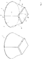
- Fig. 1 shows, by way of example, a light-shaping device 1 with an inlet opening 2 and an outlet opening 3. Between the inlet opening 2 and the outlet opening 3 extends light-shaping and light-emitting area 4, in which a circumferential side wall 5 is made of flexible material, for example a textile material. The material can also be referred to as a reflector material. Clamping elements 6 are provided to stiffen the side wall. The tensioning elements 6 extend in the longitudinal direction of the light-shaping and light-emitting region 4, with an inclination being given to the central axis of the light-shaping and light-emitting region 4.
- the clamping elements 6 go out of the corner areas of the square inlet opening 2.
- the outlet opening 3 is formed as a round outlet opening, which is at least partially surrounded by a front or outlet-side clamping element 7, which spans the flexible material of the side wall 5.
- the front-side clamping element 7 is made of a flat material, for example spring steel.
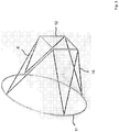
- Fig. 2 shows a perspective view of a designed as a frame base structure 10 for a light shaping device in which the clamping elements 6, which extend between the inlet opening 2 and the outlet opening 3, intersect in pairs.
- the clamping elements 6 extend between an outlet-side clamping element 11 and an inlet-side clamping element 12, wherein in the embodiment shown, the outlet-side clamping element 11 is formed as a ring.
- the entry-side clamping element 12 has a quadrangular shape.
- Fig. 2 the basic construction 10 is shown in the assembled or unfolded state.
- the base construction in the region between the outlet-side clamping element 11 and the inlet-side clamping element 12 is covered on the outside with reflector material.
- the reflector material is attached, for example, to the outlet-side clamping element 11 and the inlet-side clamping element 12, be it detachable or not detachable, for example by means of stitching. Ends of the clamping elements can be releasably inserted into associated pockets (not shown) on the inside of the reflector material.
- the bags can be designed as a storage bag, for example in the below with reference to the Fig. 5 to 7 explained training.
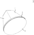
- FIG Fig. 3 Similarly to the embodiment in FIG Fig. 2 are the outlet-side clamping element 11 and the inlet-side clamping element 12 in the further light-shaping device in Fig. 3 executed. At the in Fig. 3 As shown embodiment, the clamping elements 6 are not arranged crossing.
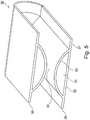
- Fig. 4 shows a perspective view of the light shaping device 1.
- a light diffusion device 20 is arranged, which is detachably attached by means of a zipper 21 shown schematically.
- the zipper can be sewn to the reflector material.
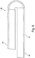
- the Fig. 5 to 7 show representations of a receiving pocket 30, which is arranged on the inside in the light shaping device 4 in the light shaping devices to accommodate end portions of the clamping elements 6, in particular proximal to the front or entry side clamping element 7, 12 arranged end portions.
- the receiving pocket 30 has a receiving space 31 which is formed between an upper and a lower portion 32, 33 of the receiving pocket 30.
- Fig. 5 the receiving pocket 30 is shown in a folded state, wherein in an intermediate region 34 between portions 35, 36 of the receiving pocket 30, a Velcro connection may be formed.
- a Velcro connection When attaching the receiving pocket on the inside of the light former this can rest with a back 37 on the reflector material, for example, sewn or attached by means of Velcro.
- the receiving pocket 30 may be sewn to the inner side wall 5 of the light shaping device 1.
Landscapes
- Engineering & Computer Science (AREA)
- General Engineering & Computer Science (AREA)
- Physics & Mathematics (AREA)
- General Physics & Mathematics (AREA)
- Non-Portable Lighting Devices Or Systems Thereof (AREA)
Description
- Die Erfindung betrifft eine Lichtformvorrichtung und eine Anordnung.
- Eine solche Lichtformvorrichtung ist zum Beispiel aus dem Dokument
WO 2013 / 178222 A1 bekannt. - Das Dokument
DE 20 2007 001 958 U1 offenbart einen dreidimensional zusammenklappbaren Lampenschirm mit einer zusammenlegbaren Schiene, die auf einer kubischen Oberfläche zusammenklappbar ist, und einer nachgiebigen Stoffabdeckung, die auf eine Ebene faltbar ist und auf einer Außenseite der zusammenlegbaren Schiene angeordnet ist und einem flexiblen Ring an einem unteren Rand davon aufweist, der in einer gewünschten Form fixierbar und faltbar ist. Die zusammenlegbare Schiene und die nachgiebige Stoffabdeckung sind verbunden und ausgefahren bzw. ausgegeben, um einen kubischen Lampenschirm zu bilden. Sie sind entsprechend zusammenklappbar, um einen dreidimensionalen Faltzustand einzunehmen. Aus dem DokumentCN 202 275 250 U ist eine Softbox bekannt, bei der ein Reflexionsschirm von mehreren Stützstreben gestützt wird, welche mit einem Trägerteil verbunden sind. Der Reflexionsschirm weist ein offenes Ende auf, an dem die Stützstreben beweglich mit dem Trägerteil verbunden sind. Zwischen jeweils zwei benachbarten Stützstreben ist eine faltbare Verbindungsstange angeordnet. AusCN 103 149 776 A ist eine ähnliche Softbox bekannt. Das DokumentUS 7,978,971 B1 offenbart eine zusammenlegbare Softbox für die Nutzung mit einem fotografischen Blitzlicht. Der zusammenlegbare Körper der Softbox besteht aus zwei miteinander verbundenen Seitenteilen und weist eine distale sowie eine proximale Öffnung auf. Die Softbox weist weiterhin ein Frontteil auf, welches lösbar mit dem distalen Ende des Körpers verbindbar ist. - Aufgabe der Erfindung ist es, eine Lichtformvorrichtung mit verbesserten Gebrauchseigenschaften zu schaffen, die flexibel einsetzbar ist, insbesondere bei Scheinwerfern für Foto- oder Filmaufnahmen.
- Nach einem Aspekt ist eine Lichtformvorrichtung zum lösbaren Montieren an einer Befestigungseinrichtung einer Beleuchtungsvorrichtung geschaffen. Die Lichtformvorrichtung weist Folgendes auf: Seitenwände aus flexiblem Material, die nach dem Montieren an einer Beleuchtungseinrichtung einen Lichtform- und Lichtabgabebereich umgeben, der sich zwischen einer Eintrittsöffnung und einer Austrittsöffnung gebildet ist; Spannelemente, die eingerichtet sind, die Seitenwände auszusteifen; und einen Befestigungsmechanismus zum lösbaren Montieren an der Befestigungseinrichtung der Beleuchtungsvorrichtung, wobei die Austrittsöffnung als runde Austrittsöffnung gebildet ist, die zumindest abschnittsweise von einem frontseitigen Spannelement umgeben wird, welches das flexible Material der Seitenwände aufspannt.
- Nach einem weiteren Aspekt ist eine Anordnung mit einer Beleuchtungsvorrichtung, insbesondere Scheinwerfer, und einer an der Beleuchtungsvorrichtung lösbar montierten Lichtformvorrichtung geschaffen.
- Die Lichtformvorrichtung kann als selbstspannende oder selbstaufspannende Lichtformvorrichtung ausgeführt sein.
- Mit der umlaufenden Seitenwand ist ein Reflektor gebildet.
- Die Eintrittsöffnung kann rund oder eckig sein, zum Beispiel mit vier oder mehr Ecken ausgeführt sein.
- Das frontseitige Spannelement kann lösbar an den Seitenwänden angeordnet sein.
- Die Spannelemente können Stabelemente aufweisen, die sich von der Eintrittsöffnung zur Austrittsöffnung in Längsrichtung des Lichtform- und Lichtabgabebereiches erstrecken.
- Zumindest ein Teil der Spannelemente kann aus einem faserverstärktem Material bestehen, insbesondere einem kohlefaserverstärktem Material.
- Das frontseitige Spannelement kann aus Metall sein, zum Beispiel Federstahl.
- Das frontseitige Spannelement kann aus einem Flachmaterial bestehen.
- Im die Austrittsöffnung umgebenden Bereich und / oder auf einer Innenseite der Seitenwände ist eine Befestigungseinrichtung zur lösbaren Befestigung einer Diffusionseinrichtung (Diffusor) angeordnet. Das frontseitige Spannelement koppelt lösbar an die Diffusionseinrichtung, wenn die Diffusionseinrichtung angebracht ist. Die Diffusionseinrichtung kann mit dem frontseitigen Spannelement zusammen vom Reflektor abnehmbar sein.
- Ein oder mehrere der Spannelemente können in zugeordneten Aufnahmetaschen in den Seitenwänden angeordnet sein.
- Es kann eine faltbare Ausgestaltung der Lichtformvorrichtung vorgesehen sein.
- Der Befestigungsmechanismus kann Druckknöpfe und / oder Klettbandabschnitte aufweisen. Alternativ oder ergänzend können ein oder mehrere magnetische Knöpfe zum Befestigungsmechanismus beitragen. Die magnetischen Knöpfen können mit einer Rasteinrichtung kombiniert werden. In einer Ausführung ist die magnetische Verbindung mittels seitlicher Relativverlagerung der magnetisch gekoppelten Teile lösbar.
- Der Befestigungsmechanismus kann eine oder mehrere Aufnahmetaschen aufweisen, in die Enden der Spannelemente eingesteckt sind.
- Zumindest ein Teil der Spannelemente kann sich kreuzend angeordnet sein.
- Zumindest ein Teil der Spannelemente kann sich nicht kreuzend angeordnet sein.
- Die Austrittsöffnung kann zumindest teilweise mit einer Lichtdiffusionseinrichtung bedeckt sein.
- Das flexible Material kann aus einem Schichtmaterial mit einem Stapel von Schichten gebildet sein, wobei die folgenden Schichten vorgesehen und miteinander verklebt sind: Textilschicht, eine metallisierte Polyesterfolienschicht und weiße Polyesterfolienschicht.
- Nachfolgend werden weitere Aspekte beschrieben.
- Es ist ein Lichtformer mit runder Abstrahlfläche realisiert, der sich zusammenlegen lässt, ohne Speedring auskommen kann (in sich selbst aufspannt und nicht über Druck auf den Scheinwerfer oder einen Speedring und direkt am Scheinwerfer befestigt werden kann). Die Lichtformvorrichtung hat ein geringes Gewicht, da Kohlefaserstreben verwendet werden können, da auf diese nur eine sehr geringe Biegekraft wirkt bzw. ein sehr geringer Biegeradius erzielt wird.
- Das Gewicht ist in der Praxis ein wichtiger Faktor, da Bügel oder Kugelkopf eines Scheinwerfers nur eine gewisse Haltekraft aufweisen (Reibung). Große Lichtformer üben aufgrund der großen Menge des verwendeten Stoffes und des Hebelgesetzes eine hohe Kraft auf die Scheinwerfer aus. Wenn ein Scheinwerfer im Freien verwendet wird, kommt zudem der Winddruck hinzu. Deshalb sind Lichtformer aus geringfügig dickerem / schwerem Stoff bspw. häufig nicht verwendbar. Runde Lichtformer sind wichtig für natürliche / runde Reflexionen auf Gegenständen und vor allem in den Augen. Dies ist beim Film sehr wichtig.
- Beim Reflektor der Lichtformvorrichtung (Seitenwände) können ausschließlich gerade Streben zum Einsatz kommen, die diesen in Richtung zwischen Scheinwerfer (Eintrittsöffnung) und Front des Reflektors (Austrittsöffnung) aufspannen, dort wo eine Diffusionseinrichtung (Diffusion) zum Weichmachen / Modifizieren des Lichts eingesetzt werden kann. Der Reflektor lässt sich dann mit den eingesetzten Streben so schmal wie ein Regenschirm zusammenlegen, ohne dass irgendetwas entfernt werden muss.
- Die Aufspannung des Reflektors kann in zirkularer Richtung mit Hilfe der Diffusion erfolgen, die einen Ring aus Federstahl (Flachstahl) aufweisen kann. Die Diffusion kann sich über eine Verdrehung ähnlich einer Acht zusammenfalten lassen. Solche Aufspannungen sind von Zelten und photographischen Reflektoren bekannt. Das heißt der Aufbau der Diffusionseinrichtung als solcher ist in verschiedenen Ausführungen bekannt. Ein Ring aus Federstahl kann sich in einem Schlauch aus Spandex (flexiblem / Stretch-Textil) befinden.
- Die Diffusion ist mit dem Reflektor zu verbinden. Hierzu kann man Klettband und / oder Druckknöpfe verwenden. Das Klett kann nicht umlaufend um die Diffusion angeordnet sein, da Klettband nicht dehnbar ist und damit die gesamte Faltung bzw. straffe Aufspannung nicht funktioniert. Es können nur Klettstücke (oder Stücke mit Druckknöpfen) um den Umfang verteilt werden. Das Klettband kann unterbrochen sein, um die Dehnbarkeit zu gewährleisten. Der Reflektor kann innen Klettband (evtl. Druckknöpfe) aufweisen, die Diffusion außen. Sie wird in den Reflektor eingefügt und spannt diesen auf.
- Üblicherweise werden verschiedene (Licht)Diffusionseinrichtungen am Filmset verwendet, um unterschiedliche Effekte zu erreichen. Somit muss die Diffusion schnell und leicht wechselbar sein. Würde man den Ring mit dem Federstahl aus dem Reflektor nehmen, kollabiert der Reflektor, dies macht das wechseln mühselig. Das Diffusionsmaterial (der Stoff) kann aus dem Federstahlring leicht entnehmbar und wieder einsetzbar sein. Eine Möglichkeit ist die Verwendung eines Reißverschlusses. Auch mehrere Reißverschlüsse können vorgesehen sein, zum Beispiel zwei. Es können ein oder mehrere flexible Reißverschlüsse verwendet werden. Weiter könnte alternativ oder ergänzend ein Klettband verwendet werden. Zudem könnten auch Haken und Ösen verwendet werden.
- Die Diffusionseinrichtung kann mit dem Reißverschluss an einem Federstahlring befestigt werden, an dem sich zwei Reißverschlüsse befinden. Mit dem zweiten Reißverschluss kann die Diffusionseinrichtung inklusiv Stahlring am Reflektor befestigt werden. Hierdurch kann die Diffusionseinrichtung in einer Ausführung ohne Entnahme des Rings gewechselt werden. Hierdurch bleibt der Reflektor in Position. Außerdem können die Diffusionseinrichtungen günstiger hergestellt werden, sind kleiner, leichter und einfacher zu transportieren.
- Es kann ein weißes oder diffuses Reflektormaterial (zum Beispiel mit Textil) verwendet werden, da ein silbernes (spiegelähnliches) Material zu ungleichmäßiger Ausleuchtung der Diffusion (Diffusionseinrichtung) führen kann.
- Herkömmliches Textil basiertes, weißes Reflektormaterial ist in der Regel nicht sehr reflektierend. Hierdurch geht viel Licht verloren, da Licht im Inneren zwischen der Diffusionseinrichtung und dem Reflektor mehrmals hin und her reflektiert wird. Dies kann zur gleichmäßigen Ausleuchtung führen, d.h. einem unerwünschter Hotspot in der Mitte. Bisher wird häufig der Weg gegangen, um einen Hotspot in der Mitte des Diffusionsmaterials zu vermeiden, dass eine zweite innere Diffusion existiert die vom Durchmesser kleiner sein kann als der Reflektor an der entsprechenden Stelle und / oder in der Mitte mehrere Lagen Textil ausweist. Das Problem ist, das diese viel Licht schluckt. Dies ist insbesondere bei LED und vor allem batteriebetriebenen Scheinwerfer problematisch, da diese nur eine begrenzte Lumenzahl bereitstellen.
- Je höher der Reflexionsgrad des Reflektormaterials ist, umso gleichmäßiger ist die Ausleuchtung der Diffusionseinrichtung und umso größer ist die Lichtausbeute bzw. Beleuchtungsstärke, da das Licht zwischen Diffusionsmaterial und Reflektor mehrmals hin und her reflektiert wird. Bei einem hochreflektierenden (diffusem) Reflektor kann die zweite innere Diffusion wegfallen. Hierdurch kann eine höhere Effizienz erreicht werden (50 bis 100% höhere Beleuchtungsstärke bei gleicher Lumenzahl des Leuchtmittels).
- Ein effizientes und leichtes Reflektor- oder Reflexionsmaterial kann realisiert werden, indem ein Textil mit einer metallisierten, für Licht hochreflektiven Folie beschichtet ist, insbesondere einer Silberfolie. Diese hochreflektive Schicht kann mit einem matten, zum Beispiel weißen Material, was hochreflektiv ist, beschichtet werden (weißes PE oder Polyester). Vorteil ist, dass man das weiße Material sehr dünn halten kann, und das Textil leicht ist und trotzdem auch kein Licht an der Rückseite austritt.
- Ein Aufbau kann wie folgt aussehen: Textil (Polyester), bevorzugt Nylon (ist sehr strapazierfähig) 150 bis 210 Denier, dann eine metallisierte (Aluminium) Polyesterfolienschicht (wahlweise beidseitig metallisiert), dann eine Schicht weiße Polyesterfolie, wobei alles mit klarem Klebstoff verklebt ist. Zur Festigkeitserhöhung kann eine Zwischenschicht aus über Kreuz laufenden dicken Fäden mit großem Abstand (ca. 20mm), die ein rombenförmiges Muster ergeben, zwischen dem Textil und der metallisierter Polyesterfolie eingebracht werden. Dadurch erhöht sich das Gewicht nur gering, aber die Festigkeit stark. Dieser Aufbau ergibt ein sehr effizientes, leichtes, diffuses und auch kostengünstiges Reflektormaterial.
- Das Material für den Reflektor kann nicht nur bei der Lichtformvorrichtung zum Einsatz kommen, sondern auch bei anderen Lichtreflektor- oder Lichtreflexionsvorrichtung, zum Beispiel einem flachen oder gekrümmten flächigen Reflektor, insbesondere Lichtreflektor- oder Lichtreflexionsvorrichtung für Bild- oder Filmaufnahmen.
- Unabhängig hiervon kann nach einem alternativen Aspekt ein Reflektormaterial vorgesehen sein, also ein lichtreflektierendes Material auf Textilbasis, bei dem ein Schichtmaterial mit aufeinanderliegenden Schichten gebildet ist, wobei die folgenden Schichten vorgesehen und miteinander verklebt sind: Textilschicht; eine metallisierte Polyesterfolienschicht, die auf der Textilschicht angeordnet ist, wobei die Metallisierung ein- oder beidseitig ausgebildet ist; und weiße Polyesterfolienschicht, die auf der metallisierte Polyesterfolienschicht angeordnet ist. Zwischen der Textilschicht und der metallisierten Polyesterfolienschicht kann eine Zwischenschicht aus über Kreuz laufenden Fäden angeordnet sein.
- Das Reflektormaterial kann alternativ Folgendes aufweisen: schwarzes Textilgewebe, insbesondere schwarzes Nylongewebe wie zum Beispiel Ripstop Nylon (70D); schwarzer Kleber; doppelt silber beschichtete Reflexionsfolie; durchsichtiger Kleber und weißes Textilgewebe, insbesondere weißes Nylongewebe wie zum Beispiel Ripstop Nylon (70D). Hierdurch können ein hoher Reflexionsgrad und eine matte ungerichtete Reflexion erreicht werden. Zudem ist das Material stabil und reißfest. Es ist eine zweite Textilschicht vorgesehen. Das Reflektormaterial kann aus einem solchen Schichtaufbau bestehen.
- Das Reflektormaterial kann in einer alternativen Ausführung Folgendes aufweisen: schwarzes Textilgewebe, insbesondere schwarzes Nylongewebe wie zum Beispiel Ripstop Nylon (70D); schwarzer Kleber; weiße Folie; durchsichtiger Kleber; doppelt Silber beschichtete Reflexionsfolie; durchsichtiger Kleber und weißes Textilgewebe, insbesondere weißes Nylongewebe wie zum Beispiel Ripstop Nylon (70D). Das Reflektormaterial kann aus einem solchen Schichtaufbau bestehen.
- Im Folgenden werden Ausführungsbeispielen unter Bezugnahme auf Figuren einer Zeichnung näher erläutert. Hierbei zeigen:
- Fig. 1
- eine schematische Darstellung einer Lichtformvorrichtung mit einer Eintrittsöffnung und einer Austrittsöffnung,
- Fig. 2
- eine schematische perspektivische Darstellung einer Spanneinrichtung (Basiskonstruktion) für einen anderen Lichtformer,
- Fig. 3
- eine schematische Darstellung für eine Spanneinrichtung eines weiteren Lichtformers,
- Fig. 4
- eine perspektivische Darstellung eines Lichtformers, bei dem im Bereich einer Austrittsöffnung eine Diffusionseinrichtung angeordnet ist,
- Fig. 5
- eine perspektivische Darstellung einer Aufnahmetasche,
- Fig. 6
- eine Darstellung der Aufnahmetasche von der Seite,
- Fig. 7
- eine perspektivische Darstellung der Aufnahmetasche aus
Fig. 5 in einem aufgeklappten Zustand. -
Fig. 1 zeigt beispielhaft eine Lichtformvorrichtung 1 mit einer Eintrittsöffnung 2 und einer Austrittsöffnung 3. Zwischen der Eintrittsöffnung 2 und der Austrittsöffnung 3 erstreckt sich Lichtform- und Lichtabgabebereich 4, bei dem eine umlaufende Seitenwand 5 aus flexiblem Material ist, zum Beispiel einem Textilmaterial. Das Material kann auch als Reflektormaterial bezeichnet werden. Spannelemente 6 sind vorgesehen, um die Seitenwand auszusteifen. Die Spannelemente 6 verlaufen in Längsrichtung des Lichtform- und Lichtabgabebereiches 4, wobei eine Schrägstellung zur Mittelachse des Lichtform- und Lichtabgabebereiches 4 gegeben ist. - Die Spannelemente 6 gehen Eckbereichen der viereckigen Eintrittsöffnung 2 aus.
- Die Austrittsöffnung 3 als runde Austrittsöffnung gebildet, die zumindest abschnittsweise von einem front- oder austrittsseitigen Spannelement 7 umgeben wird, welches das flexible Material der Seitenwand 5 aufspannt. Das frontseitige Spannelement 7 ist aus einem Flachmaterial, zum Beispiel Federstahl.
- Es ist ein Lichtformer mit einer runden Abstrahlfläche geschaffen, der sehr effizient ist, eine gleichmäßige Ausleuchtung liefert, sehr leicht ist und damit auch sehr groß (135cm Durchmesser und mehr) gebaut werden kann und auch für kleinere Scheinwerfer insbesondere LED Scheinwerfer, deren Haltersystem in der Regel nur für geringe Haltekräfte ausgelegt sind, verwendet werden kann. Zudem weist er ein kleines Packmaß auf und ist kostengünstig herstellbar.
-
Fig. 2 zeigt eine perspektivische Darstellung einer als Gestell ausgeführten Basiskonstruktion 10 für eine Lichtformvorrichtung, bei der sich die Spannelemente 6, die sich zwischen der Eintrittsöffnung 2 und der Austrittsöffnung 3 erstrecken, paarweise kreuzen. Die Spannelemente 6 erstrecken sich zwischen einem austrittsseitigen Spannelement 11 und einem eintrittsseitigen Spannelement 12, wobei in der gezeigten Ausführungsform das austrittseitige Spannelement 11 als ein Ring gebildet ist. Das eintrittsseitige Spannelement 12 weist eine Viereckform auf. - In
Fig. 2 ist die Basiskonstruktion 10 im aufgebauten oder aufgespannten Zustand gezeigt. Zum Ausbilden der Lichtformvorrichtung wird die Basiskonstruktion im Bereich zwischen dem austrittsseitigen Spannelement 11 und dem eintrittsseitigen Spannelement 12 außenseitig mit Reflektormaterial bespannt. Hierbei wird das Reflektormaterial zum Beispiel an dem austrittsseitigen Spannelement 11 und dem eintrittsseitigen Spannelement 12 befestigt, sei es lösbar oder nicht lösbar, zum Beispiel mittels umnähen. Enden der Spannelemente können lösbar in zugeordnete Taschen (nicht dargestellt) auf der Innenseite des Reflektormaterials eingesteckt werden. Die Taschen können als Aufnahmetasche ausgeführt, zum Beispiel in der unten unter Bezugnahme auf dieFig. 5 bis 7 erläuterten Ausbildung. - In ähnlicher Weise zur Ausgestaltung in
Fig. 2 sind das austrittseitige Spannelement 11 sowie das eintrittsseitige Spannelement 12 bei der weiteren Lichtformvorrichtung inFig. 3 ausgeführt. Bei der inFig. 3 gezeigten Ausführung sind die Spannelemente 6 nicht kreuzend angeordnet. -
Fig. 4 zeigt eine perspektivische Darstellung der Lichtformvorrichtung 1. Im Bereich der Austrittsöffnung 3 ist eine Lichtdiffusionsvorrichtung 20 angeordnet, die mittels eines schematisch dargestellten Reißverschlusses 21 lösbar angebracht ist. Der Reißverschluss kann an das Reflektormaterial angenäht sein. - Die
Fig. 5 bis 7 zeigen Darstellungen einer Aufnahmetasche 30, die bei den Lichtformvorrichtungen innenseitig im Lichtformbereich 4 angeordnet ist, um Endabschnitte der Spannelemente 6 aufzunehmen, insbesondere proximal zum front- oder eintrittsseitigen Spannelement 7, 12 angeordnete Endabschnitte. Die Aufnahmetasche 30 weist einen Aufnahmeraum 31 auf, der zwischen einem oberen und einem unteren Abschnitt 32, 33 der Aufnahmetasche 30 gebildet ist. - In
Fig. 5 ist die Aufnahmetasche 30 in einem umgeschlagenen Zustand gezeigt, wobei in einem Zwischenbereich 34 zwischen Abschnitten 35, 36 der Aufnahmetasche 30 eine Klettverbindung ausgebildet sein kann. Beim Anbringen der Aufnahmetasche auf der Innenseite des Lichtformers kann diese mit einer Rückseite 37 auf dem Reflektormaterial aufliegen, zum Beispiel angenäht oder mittels Klettband befestigt sein. Die Aufnahmetasche 30 kann an der umlaufenden Seitenwand 5 der Lichtformvorrichtung 1 innenseitig angenäht sein. - Die in der vorstehenden Beschreibung, den Ansprüchen sowie der Zeichnung offenbarten Merkmale können sowohl einzeln als auch in beliebiger Kombination für die Verwirklichung der verschiedenen Ausführungen von Bedeutung sein.
Claims (14)
- Lichtformvorrichtung (1) zum lösbaren Montieren an einer Befestigungseinrichtung einer Beleuchtungsvorrichtung, mit- Seitenwänden (5) aus flexiblem Material, die nach dem Montieren an einer Beleuchtungseinrichtung einen Lichtform- und Lichtabgabebereich (4) umgeben, der zwischen einer Eintrittsöffnung (2) und einer Austrittsöffnung (3) gebildet ist,- Spannelemente (6), die eingerichtet sind, die Seitenwände (5) auszusteifen, und- einem Befestigungsmechanismus zum lösbaren Montieren an der Befestigungseinrichtung der Beleuchtungsvorrichtung,dadurch gekennzeichnet, dass- die Austrittsöffnung (3) als runde Austrittsöffnung gebildet ist, die zumindest abschnittsweise von einem frontseitigen Spannelement (7, 11) umgeben wird, welches das flexible Material der Seitenwände (5) aufspannt,- im die Austrittsöffnung (3) umgebenden Bereich und / oder auf einer Innenseite der Seitenwände (5) eine Befestigungseinrichtung zur lösbaren Befestigung einer Diffusionseinrichtung (20) angeordnet ist und- das frontseitige Spannelement (7, 11) lösbar an die Diffusionseinrichtung (20) koppelt, wenn diese angebracht ist.
- Lichtformvorrichtung (1) nach Anspruch 1, dadurch gekennzeichnet, dass die Spannelemente (6) Stabelemente aufweisen, die sich von der Eintrittsöffnung (2) zur Austrittsöffnung (3) in Längsrichtung des Lichtform- und Lichtabgabebereiches (4) erstrecken.
- Lichtformvorrichtung (1) nach Anspruch 1 oder 2, dadurch gekennzeichnet, dass zumindest ein Teil der Spannelemente (6) aus einem faserverstärktem Material besteht, insbesondere einem kohlefaserverstärktem Material.
- Lichtformvorrichtung (1) nach mindestens einem der vorangehenden Ansprüche, dadurch gekennzeichnet, dass das frontseitige Spannelement (7, 11) aus Metall ist.
- Lichtformvorrichtung (1) nach mindestens einem der vorangehenden Ansprüche, dadurch gekennzeichnet, dass das frontseitige Spannelement (7,11) aus einem Flachmaterial ist.
- Lichtformvorrichtung (1) nach mindestens einem der vorangehenden Ansprüche, dadurch gekennzeichnet, dass ein oder mehrere der Spannelemente (6) in zugeordneten Aufnahmetaschen (30) in den Seitenwänden angeordnet sind.
- Lichtformvorrichtung (1) nach mindestens einem der vorangehenden Ansprüche, gekennzeichnet durch eine faltbare Ausgestaltung.
- Lichtformvorrichtung (1) nach mindestens einem der vorangehenden Ansprüche, dadurch gekennzeichnet, dass der Befestigungsmechanismus Druckknöpfe und / oder Klettbandabschnitte aufweist.
- Lichtformvorrichtung (1) nach mindestens einem der vorangehenden Ansprüche, dadurch gekennzeichnet, dass der Befestigungsmechanismus eine oder mehrere Aufnahmetaschen (30) aufweist, in die Enden der Spannelemente (6) eingesteckt sind.
- Lichtformvorrichtung (1) nach mindestens einem der vorangehenden Ansprüche, dadurch gekennzeichnet, dass zumindest ein Teil der Spannelemente (6) sich kreuzend angeordnet sind.
- Lichtformvorrichtung (1) nach mindestens einem der vorangehenden Ansprüche, dadurch gekennzeichnet, dass zumindest ein Teil der Spannelemente (6) sich nicht kreuzend angeordnet sind.
- Lichtformvorrichtung (1) nach mindestens einem der vorangehenden Ansprüche, dadurch gekennzeichnet, dass die Austrittsöffnung (3) zumindest teilweise mit der Lichtdiffusionseinrichtung (20) bedeckt ist.
- Lichtformvorrichtung (1) nach mindestens einem der vorangehenden Ansprüche, dadurch gekennzeichnet, dass das flexible Material aus einem Schichtmaterial mit einem Stapel von Schichten gebildet ist, wobei die folgenden verklebten Schichten vorgesehen sind: Textilschicht, eine metallisierte Polyesterfolienschicht und weiße Polyesterfolienschicht.
- Anordnung, mit einer Beleuchtungsvorrichtung, insbesondere Scheinwerfer, und einer an der Beleuchtungsvorrichtung lösbar montierten Lichtformvorrichtung (1) nach mindestens einem der vorangehenden Ansprüche.
Priority Applications (1)
| Application Number | Priority Date | Filing Date | Title |
|---|---|---|---|
| PL15721538T PL3129705T3 (pl) | 2014-04-07 | 2015-04-07 | Urządzenie kształtujące światło oraz układ |
Applications Claiming Priority (2)
| Application Number | Priority Date | Filing Date | Title |
|---|---|---|---|
| DE102014104924.1A DE102014104924A1 (de) | 2014-04-07 | 2014-04-07 | Selbstaufspannende Lichtformvorrichtung und Anordnung |
| PCT/DE2015/100145 WO2015154754A1 (de) | 2014-04-07 | 2015-04-07 | Lichtformvorrichtung und anordnung |
Publications (3)
| Publication Number | Publication Date |
|---|---|
| EP3129705A1 EP3129705A1 (de) | 2017-02-15 |
| EP3129705B1 true EP3129705B1 (de) | 2018-06-13 |
| EP3129705B8 EP3129705B8 (de) | 2018-07-25 |
Family
ID=53175208
Family Applications (1)
| Application Number | Title | Priority Date | Filing Date |
|---|---|---|---|
| EP15721538.5A Not-in-force EP3129705B8 (de) | 2014-04-07 | 2015-04-07 | Lichtformvorrichtung und anordnung |
Country Status (6)
| Country | Link |
|---|---|
| US (1) | US20170227191A1 (de) |
| EP (1) | EP3129705B8 (de) |
| CN (1) | CN106233068A (de) |
| DE (1) | DE102014104924A1 (de) |
| PL (1) | PL3129705T3 (de) |
| WO (1) | WO2015154754A1 (de) |
Families Citing this family (2)
| Publication number | Priority date | Publication date | Assignee | Title |
|---|---|---|---|---|
| DE202016101460U1 (de) * | 2016-03-16 | 2016-03-29 | Markus Kreuzer | Vorrichtung zur Beeinflussung des Lichts bei Fotoaufnahmen |
| CN111736409B (zh) * | 2020-07-07 | 2022-03-08 | 滨州职业学院 | 一种适用于电影拍摄用的补光灯罩 |
Citations (1)
| Publication number | Priority date | Publication date | Assignee | Title |
|---|---|---|---|---|
| CN103149776A (zh) * | 2013-01-21 | 2013-06-12 | 深圳市元科摄影器材有限公司 | 一种摄影灯变光装置 |
Family Cites Families (12)
| Publication number | Priority date | Publication date | Assignee | Title |
|---|---|---|---|---|
| US4446506A (en) * | 1982-11-12 | 1984-05-01 | Larson Enterprises, Inc. | Photographic light diffuser |
| DE8702694U1 (de) * | 1987-02-21 | 1987-04-23 | Bron Elektronik AG, Allschwil, Basel | Reflektor für fotografische Lichtquellen |
| US5154503A (en) * | 1991-03-11 | 1992-10-13 | F. J. Westcott Company | Photographic light modifier |
| US5311409A (en) * | 1993-06-14 | 1994-05-10 | Camera World, Inc. | Collapsible photographic light diffuser |
| US6709121B1 (en) * | 2002-09-24 | 2004-03-23 | Chimera Company | Lightbank with releasable support rod mounts |
| US7063428B2 (en) * | 2003-10-28 | 2006-06-20 | Chimera Company | Removable lightbank extension |
| US7470044B2 (en) * | 2006-03-22 | 2008-12-30 | The Picture People | Light diffusion device |
| US7978971B1 (en) * | 2010-03-26 | 2011-07-12 | David Honl | Collapsible softbox for photography lighting |
| DE202007001958U1 (de) * | 2007-02-06 | 2007-04-19 | Lien, Wen-Cheng | Dreidimensional zusammenklappbarer Lampenschirm |
| CN202275250U (zh) * | 2011-09-27 | 2012-06-13 | 深圳市元科摄影器材有限公司 | 柔光箱 |
| US8833951B1 (en) * | 2012-02-01 | 2014-09-16 | Olexandr Pavlenko | Assemble-free fast deployable light modifier |
| DE102012104779A1 (de) | 2012-06-01 | 2013-12-05 | Sumolight Gmbh | Beleuchtungsvorrichtung und Scheinwerfer |
-
2014
- 2014-04-07 DE DE102014104924.1A patent/DE102014104924A1/de not_active Withdrawn
-
2015
- 2015-04-07 US US15/302,174 patent/US20170227191A1/en not_active Abandoned
- 2015-04-07 WO PCT/DE2015/100145 patent/WO2015154754A1/de not_active Ceased
- 2015-04-07 PL PL15721538T patent/PL3129705T3/pl unknown
- 2015-04-07 EP EP15721538.5A patent/EP3129705B8/de not_active Not-in-force
- 2015-04-07 CN CN201580018665.8A patent/CN106233068A/zh active Pending
Patent Citations (1)
| Publication number | Priority date | Publication date | Assignee | Title |
|---|---|---|---|---|
| CN103149776A (zh) * | 2013-01-21 | 2013-06-12 | 深圳市元科摄影器材有限公司 | 一种摄影灯变光装置 |
Also Published As
| Publication number | Publication date |
|---|---|
| EP3129705B8 (de) | 2018-07-25 |
| EP3129705A1 (de) | 2017-02-15 |
| CN106233068A (zh) | 2016-12-14 |
| DE102014104924A1 (de) | 2015-10-08 |
| WO2015154754A1 (de) | 2015-10-15 |
| US20170227191A1 (en) | 2017-08-10 |
| PL3129705T3 (pl) | 2019-02-28 |
Similar Documents
| Publication | Publication Date | Title |
|---|---|---|
| EP3129705B1 (de) | Lichtformvorrichtung und anordnung | |
| EP2171349B1 (de) | Faltbarer reflektorschirm | |
| WO2022144168A1 (de) | Aufblasbarer leuchtkörper | |
| DE102013004665B4 (de) | Softbox | |
| WO2009000556A1 (de) | Diffusor zum lösbaren befestigen an einem reflektorschirm oder dergleichen | |
| DE102008003352B4 (de) | Beleuchtungsvorrichtung | |
| DE102016014803B4 (de) | Aufbau eines aufblasbaren Lampenschirms für eine Arbeitslampe | |
| DE202014003499U1 (de) | Faltbare Schutzhülle | |
| DE3705525A1 (de) | Zusammenlegbarer lampenschirm | |
| DE202010015722U1 (de) | Lampenschirm | |
| AT10605U1 (de) | Rucksack mit hartschale und aktiver beleuchtung | |
| DE102008005601B4 (de) | Lampenschirm | |
| DE102019111015A1 (de) | Vorrichtung zur Ausleuchtung eines Motivbereichs | |
| DE102016012600A1 (de) | Beleuchtungseinrichtung für Transport- oder Fortbewegungsmittel | |
| DE949461C (de) | Faecherartig zusammenklappbarer Reflektor | |
| DE102015002803B3 (de) | Reflektor, der zwischen einem aufgefächerten und einem zusammengefächerten Zustand um ein zentrales im Querschnitt kreisförmiges Trägerelement herum fächerbar ist. | |
| DE2035949A1 (de) | Lampenschirm | |
| EP4078287B1 (de) | Reflektorschirm mit gerafftem reflexionselement sowie reflektoranordnung mit einem solchen reflektorschirm | |
| AT519746B1 (de) | Signalschleife | |
| DE102019111014A1 (de) | Vorrichtung zur Ausleuchtung eines Motivbereichs | |
| DE29918967U1 (de) | Leuchte/Beleuchtung/Displaysystem | |
| EP3220194B1 (de) | Vorrichtung zur beeinflussung des lichts bei fotoaufnahmen | |
| AT503962A4 (de) | Aufblasbarer formkörper | |
| EP2924346B1 (de) | Optik für eine leuchte | |
| DE20005187U1 (de) | Leuchtenschirmvorrichtung |
Legal Events
| Date | Code | Title | Description |
|---|---|---|---|
| STAA | Information on the status of an ep patent application or granted ep patent |
Free format text: STATUS: THE INTERNATIONAL PUBLICATION HAS BEEN MADE |
|
| PUAI | Public reference made under article 153(3) epc to a published international application that has entered the european phase |
Free format text: ORIGINAL CODE: 0009012 |
|
| STAA | Information on the status of an ep patent application or granted ep patent |
Free format text: STATUS: REQUEST FOR EXAMINATION WAS MADE |
|
| 17P | Request for examination filed |
Effective date: 20161102 |
|
| AK | Designated contracting states |
Kind code of ref document: A1 Designated state(s): AL AT BE BG CH CY CZ DE DK EE ES FI FR GB GR HR HU IE IS IT LI LT LU LV MC MK MT NL NO PL PT RO RS SE SI SK SM TR |
|
| AX | Request for extension of the european patent |
Extension state: BA ME |
|
| DAV | Request for validation of the european patent (deleted) | ||
| DAX | Request for extension of the european patent (deleted) | ||
| GRAP | Despatch of communication of intention to grant a patent |
Free format text: ORIGINAL CODE: EPIDOSNIGR1 |
|
| STAA | Information on the status of an ep patent application or granted ep patent |
Free format text: STATUS: GRANT OF PATENT IS INTENDED |
|
| INTG | Intention to grant announced |
Effective date: 20171215 |
|
| GRAS | Grant fee paid |
Free format text: ORIGINAL CODE: EPIDOSNIGR3 |
|
| GRAA | (expected) grant |
Free format text: ORIGINAL CODE: 0009210 |
|
| STAA | Information on the status of an ep patent application or granted ep patent |
Free format text: STATUS: THE PATENT HAS BEEN GRANTED |
|
| AK | Designated contracting states |
Kind code of ref document: B1 Designated state(s): AL AT BE BG CH CY CZ DE DK EE ES FI FR GB GR HR HU IE IS IT LI LT LU LV MC MK MT NL NO PL PT RO RS SE SI SK SM TR |
|
| REG | Reference to a national code |
Ref country code: GB Ref legal event code: FG4D Free format text: NOT ENGLISH |
|
| REG | Reference to a national code |
Ref country code: CH Ref legal event code: EP Ref country code: AT Ref legal event code: REF Ref document number: 1008864 Country of ref document: AT Kind code of ref document: T Effective date: 20180615 |
|
| RAP2 | Party data changed (patent owner data changed or rights of a patent transferred) |
Owner name: SUMOLIGHT GMBH |
|
| REG | Reference to a national code |
Ref country code: IE Ref legal event code: FG4D Free format text: LANGUAGE OF EP DOCUMENT: GERMAN |
|
| RIN2 | Information on inventor provided after grant (corrected) |
Inventor name: YELLIN, DAVID Inventor name: POLACZEK, RALF |
|
| REG | Reference to a national code |
Ref country code: DE Ref legal event code: R096 Ref document number: 502015004677 Country of ref document: DE |
|
| REG | Reference to a national code |
Ref country code: NL Ref legal event code: MP Effective date: 20180613 |
|
| REG | Reference to a national code |
Ref country code: LT Ref legal event code: MG4D |
|
| PG25 | Lapsed in a contracting state [announced via postgrant information from national office to epo] |
Ref country code: ES Free format text: LAPSE BECAUSE OF FAILURE TO SUBMIT A TRANSLATION OF THE DESCRIPTION OR TO PAY THE FEE WITHIN THE PRESCRIBED TIME-LIMIT Effective date: 20180613 Ref country code: NO Free format text: LAPSE BECAUSE OF FAILURE TO SUBMIT A TRANSLATION OF THE DESCRIPTION OR TO PAY THE FEE WITHIN THE PRESCRIBED TIME-LIMIT Effective date: 20180913 Ref country code: SE Free format text: LAPSE BECAUSE OF FAILURE TO SUBMIT A TRANSLATION OF THE DESCRIPTION OR TO PAY THE FEE WITHIN THE PRESCRIBED TIME-LIMIT Effective date: 20180613 Ref country code: BG Free format text: LAPSE BECAUSE OF FAILURE TO SUBMIT A TRANSLATION OF THE DESCRIPTION OR TO PAY THE FEE WITHIN THE PRESCRIBED TIME-LIMIT Effective date: 20180913 Ref country code: FI Free format text: LAPSE BECAUSE OF FAILURE TO SUBMIT A TRANSLATION OF THE DESCRIPTION OR TO PAY THE FEE WITHIN THE PRESCRIBED TIME-LIMIT Effective date: 20180613 Ref country code: LT Free format text: LAPSE BECAUSE OF FAILURE TO SUBMIT A TRANSLATION OF THE DESCRIPTION OR TO PAY THE FEE WITHIN THE PRESCRIBED TIME-LIMIT Effective date: 20180613 Ref country code: CY Free format text: LAPSE BECAUSE OF FAILURE TO SUBMIT A TRANSLATION OF THE DESCRIPTION OR TO PAY THE FEE WITHIN THE PRESCRIBED TIME-LIMIT Effective date: 20180613 |
|
| PG25 | Lapsed in a contracting state [announced via postgrant information from national office to epo] |
Ref country code: LV Free format text: LAPSE BECAUSE OF FAILURE TO SUBMIT A TRANSLATION OF THE DESCRIPTION OR TO PAY THE FEE WITHIN THE PRESCRIBED TIME-LIMIT Effective date: 20180613 Ref country code: RS Free format text: LAPSE BECAUSE OF FAILURE TO SUBMIT A TRANSLATION OF THE DESCRIPTION OR TO PAY THE FEE WITHIN THE PRESCRIBED TIME-LIMIT Effective date: 20180613 Ref country code: HR Free format text: LAPSE BECAUSE OF FAILURE TO SUBMIT A TRANSLATION OF THE DESCRIPTION OR TO PAY THE FEE WITHIN THE PRESCRIBED TIME-LIMIT Effective date: 20180613 Ref country code: GR Free format text: LAPSE BECAUSE OF FAILURE TO SUBMIT A TRANSLATION OF THE DESCRIPTION OR TO PAY THE FEE WITHIN THE PRESCRIBED TIME-LIMIT Effective date: 20180914 |
|
| PG25 | Lapsed in a contracting state [announced via postgrant information from national office to epo] |
Ref country code: NL Free format text: LAPSE BECAUSE OF FAILURE TO SUBMIT A TRANSLATION OF THE DESCRIPTION OR TO PAY THE FEE WITHIN THE PRESCRIBED TIME-LIMIT Effective date: 20180613 |
|
| PG25 | Lapsed in a contracting state [announced via postgrant information from national office to epo] |
Ref country code: RO Free format text: LAPSE BECAUSE OF FAILURE TO SUBMIT A TRANSLATION OF THE DESCRIPTION OR TO PAY THE FEE WITHIN THE PRESCRIBED TIME-LIMIT Effective date: 20180613 Ref country code: IS Free format text: LAPSE BECAUSE OF FAILURE TO SUBMIT A TRANSLATION OF THE DESCRIPTION OR TO PAY THE FEE WITHIN THE PRESCRIBED TIME-LIMIT Effective date: 20181013 Ref country code: EE Free format text: LAPSE BECAUSE OF FAILURE TO SUBMIT A TRANSLATION OF THE DESCRIPTION OR TO PAY THE FEE WITHIN THE PRESCRIBED TIME-LIMIT Effective date: 20180613 Ref country code: SK Free format text: LAPSE BECAUSE OF FAILURE TO SUBMIT A TRANSLATION OF THE DESCRIPTION OR TO PAY THE FEE WITHIN THE PRESCRIBED TIME-LIMIT Effective date: 20180613 |
|
| PG25 | Lapsed in a contracting state [announced via postgrant information from national office to epo] |
Ref country code: SM Free format text: LAPSE BECAUSE OF FAILURE TO SUBMIT A TRANSLATION OF THE DESCRIPTION OR TO PAY THE FEE WITHIN THE PRESCRIBED TIME-LIMIT Effective date: 20180613 |
|
| REG | Reference to a national code |
Ref country code: DE Ref legal event code: R097 Ref document number: 502015004677 Country of ref document: DE |
|
| PLBE | No opposition filed within time limit |
Free format text: ORIGINAL CODE: 0009261 |
|
| STAA | Information on the status of an ep patent application or granted ep patent |
Free format text: STATUS: NO OPPOSITION FILED WITHIN TIME LIMIT |
|
| 26N | No opposition filed |
Effective date: 20190314 |
|
| PG25 | Lapsed in a contracting state [announced via postgrant information from national office to epo] |
Ref country code: DK Free format text: LAPSE BECAUSE OF FAILURE TO SUBMIT A TRANSLATION OF THE DESCRIPTION OR TO PAY THE FEE WITHIN THE PRESCRIBED TIME-LIMIT Effective date: 20180613 Ref country code: SI Free format text: LAPSE BECAUSE OF FAILURE TO SUBMIT A TRANSLATION OF THE DESCRIPTION OR TO PAY THE FEE WITHIN THE PRESCRIBED TIME-LIMIT Effective date: 20180613 |
|
| PGFP | Annual fee paid to national office [announced via postgrant information from national office to epo] |
Ref country code: CZ Payment date: 20190429 Year of fee payment: 5 Ref country code: PL Payment date: 20190429 Year of fee payment: 5 Ref country code: IT Payment date: 20190423 Year of fee payment: 5 |
|
| PG25 | Lapsed in a contracting state [announced via postgrant information from national office to epo] |
Ref country code: AL Free format text: LAPSE BECAUSE OF FAILURE TO SUBMIT A TRANSLATION OF THE DESCRIPTION OR TO PAY THE FEE WITHIN THE PRESCRIBED TIME-LIMIT Effective date: 20180613 |
|
| REG | Reference to a national code |
Ref country code: CH Ref legal event code: PL |
|
| REG | Reference to a national code |
Ref country code: BE Ref legal event code: MM Effective date: 20190430 |
|
| PG25 | Lapsed in a contracting state [announced via postgrant information from national office to epo] |
Ref country code: MC Free format text: LAPSE BECAUSE OF FAILURE TO SUBMIT A TRANSLATION OF THE DESCRIPTION OR TO PAY THE FEE WITHIN THE PRESCRIBED TIME-LIMIT Effective date: 20180613 Ref country code: LU Free format text: LAPSE BECAUSE OF NON-PAYMENT OF DUE FEES Effective date: 20190407 |
|
| PG25 | Lapsed in a contracting state [announced via postgrant information from national office to epo] |
Ref country code: LI Free format text: LAPSE BECAUSE OF NON-PAYMENT OF DUE FEES Effective date: 20190430 Ref country code: CH Free format text: LAPSE BECAUSE OF NON-PAYMENT OF DUE FEES Effective date: 20190430 |
|
| PG25 | Lapsed in a contracting state [announced via postgrant information from national office to epo] |
Ref country code: BE Free format text: LAPSE BECAUSE OF NON-PAYMENT OF DUE FEES Effective date: 20190430 |
|
| PG25 | Lapsed in a contracting state [announced via postgrant information from national office to epo] |
Ref country code: TR Free format text: LAPSE BECAUSE OF FAILURE TO SUBMIT A TRANSLATION OF THE DESCRIPTION OR TO PAY THE FEE WITHIN THE PRESCRIBED TIME-LIMIT Effective date: 20180613 |
|
| PG25 | Lapsed in a contracting state [announced via postgrant information from national office to epo] |
Ref country code: IE Free format text: LAPSE BECAUSE OF NON-PAYMENT OF DUE FEES Effective date: 20190407 |
|
| PG25 | Lapsed in a contracting state [announced via postgrant information from national office to epo] |
Ref country code: PT Free format text: LAPSE BECAUSE OF FAILURE TO SUBMIT A TRANSLATION OF THE DESCRIPTION OR TO PAY THE FEE WITHIN THE PRESCRIBED TIME-LIMIT Effective date: 20181015 |
|
| PGFP | Annual fee paid to national office [announced via postgrant information from national office to epo] |
Ref country code: FR Payment date: 20200526 Year of fee payment: 6 Ref country code: DE Payment date: 20200511 Year of fee payment: 6 |
|
| PGFP | Annual fee paid to national office [announced via postgrant information from national office to epo] |
Ref country code: GB Payment date: 20200520 Year of fee payment: 6 |
|
| PG25 | Lapsed in a contracting state [announced via postgrant information from national office to epo] |
Ref country code: CZ Free format text: LAPSE BECAUSE OF NON-PAYMENT OF DUE FEES Effective date: 20200407 |
|
| REG | Reference to a national code |
Ref country code: AT Ref legal event code: MM01 Ref document number: 1008864 Country of ref document: AT Kind code of ref document: T Effective date: 20200407 |
|
| PG25 | Lapsed in a contracting state [announced via postgrant information from national office to epo] |
Ref country code: MT Free format text: LAPSE BECAUSE OF FAILURE TO SUBMIT A TRANSLATION OF THE DESCRIPTION OR TO PAY THE FEE WITHIN THE PRESCRIBED TIME-LIMIT Effective date: 20180613 Ref country code: HU Free format text: LAPSE BECAUSE OF FAILURE TO SUBMIT A TRANSLATION OF THE DESCRIPTION OR TO PAY THE FEE WITHIN THE PRESCRIBED TIME-LIMIT; INVALID AB INITIO Effective date: 20150407 |
|
| PG25 | Lapsed in a contracting state [announced via postgrant information from national office to epo] |
Ref country code: AT Free format text: LAPSE BECAUSE OF NON-PAYMENT OF DUE FEES Effective date: 20200407 |
|
| PG25 | Lapsed in a contracting state [announced via postgrant information from national office to epo] |
Ref country code: IT Free format text: LAPSE BECAUSE OF NON-PAYMENT OF DUE FEES Effective date: 20200407 |
|
| REG | Reference to a national code |
Ref country code: DE Ref legal event code: R119 Ref document number: 502015004677 Country of ref document: DE |
|
| GBPC | Gb: european patent ceased through non-payment of renewal fee |
Effective date: 20210407 |
|
| PG25 | Lapsed in a contracting state [announced via postgrant information from national office to epo] |
Ref country code: DE Free format text: LAPSE BECAUSE OF NON-PAYMENT OF DUE FEES Effective date: 20211103 Ref country code: FR Free format text: LAPSE BECAUSE OF NON-PAYMENT OF DUE FEES Effective date: 20210430 Ref country code: GB Free format text: LAPSE BECAUSE OF NON-PAYMENT OF DUE FEES Effective date: 20210407 |
|
| PG25 | Lapsed in a contracting state [announced via postgrant information from national office to epo] |
Ref country code: MK Free format text: LAPSE BECAUSE OF FAILURE TO SUBMIT A TRANSLATION OF THE DESCRIPTION OR TO PAY THE FEE WITHIN THE PRESCRIBED TIME-LIMIT Effective date: 20180613 |
|
| PG25 | Lapsed in a contracting state [announced via postgrant information from national office to epo] |
Ref country code: PL Free format text: LAPSE BECAUSE OF NON-PAYMENT OF DUE FEES Effective date: 20200407 |