EP3126716B1 - Getriebesteuerung - Google Patents
Getriebesteuerung Download PDFInfo
- Publication number
- EP3126716B1 EP3126716B1 EP15716732.1A EP15716732A EP3126716B1 EP 3126716 B1 EP3126716 B1 EP 3126716B1 EP 15716732 A EP15716732 A EP 15716732A EP 3126716 B1 EP3126716 B1 EP 3126716B1
- Authority
- EP
- European Patent Office
- Prior art keywords
- actuator
- valve
- transmission
- controller according
- transmission controller
- Prior art date
- Legal status (The legal status is an assumption and is not a legal conclusion. Google has not performed a legal analysis and makes no representation as to the accuracy of the status listed.)
- Active
Links
Images


Classifications
-
- F—MECHANICAL ENGINEERING; LIGHTING; HEATING; WEAPONS; BLASTING
- F16—ENGINEERING ELEMENTS AND UNITS; GENERAL MEASURES FOR PRODUCING AND MAINTAINING EFFECTIVE FUNCTIONING OF MACHINES OR INSTALLATIONS; THERMAL INSULATION IN GENERAL
- F16H—GEARING
- F16H61/00—Control functions within control units of change-speed- or reversing-gearings for conveying rotary motion ; Control of exclusively fluid gearing, friction gearing, gearings with endless flexible members or other particular types of gearing
- F16H61/02—Control functions within control units of change-speed- or reversing-gearings for conveying rotary motion ; Control of exclusively fluid gearing, friction gearing, gearings with endless flexible members or other particular types of gearing characterised by the signals used
- F16H61/0262—Control functions within control units of change-speed- or reversing-gearings for conveying rotary motion ; Control of exclusively fluid gearing, friction gearing, gearings with endless flexible members or other particular types of gearing characterised by the signals used the signals being hydraulic
- F16H61/0265—Control functions within control units of change-speed- or reversing-gearings for conveying rotary motion ; Control of exclusively fluid gearing, friction gearing, gearings with endless flexible members or other particular types of gearing characterised by the signals used the signals being hydraulic for gearshift control, e.g. control functions for performing shifting or generation of shift signals
- F16H61/0267—Layout of hydraulic control circuits, e.g. arrangement of valves
-
- F—MECHANICAL ENGINEERING; LIGHTING; HEATING; WEAPONS; BLASTING
- F16—ENGINEERING ELEMENTS AND UNITS; GENERAL MEASURES FOR PRODUCING AND MAINTAINING EFFECTIVE FUNCTIONING OF MACHINES OR INSTALLATIONS; THERMAL INSULATION IN GENERAL
- F16H—GEARING
- F16H61/00—Control functions within control units of change-speed- or reversing-gearings for conveying rotary motion ; Control of exclusively fluid gearing, friction gearing, gearings with endless flexible members or other particular types of gearing
- F16H61/0021—Generation or control of line pressure
- F16H61/0025—Supply of control fluid; Pumps therefore
-
- F—MECHANICAL ENGINEERING; LIGHTING; HEATING; WEAPONS; BLASTING
- F16—ENGINEERING ELEMENTS AND UNITS; GENERAL MEASURES FOR PRODUCING AND MAINTAINING EFFECTIVE FUNCTIONING OF MACHINES OR INSTALLATIONS; THERMAL INSULATION IN GENERAL
- F16H—GEARING
- F16H61/00—Control functions within control units of change-speed- or reversing-gearings for conveying rotary motion ; Control of exclusively fluid gearing, friction gearing, gearings with endless flexible members or other particular types of gearing
- F16H61/02—Control functions within control units of change-speed- or reversing-gearings for conveying rotary motion ; Control of exclusively fluid gearing, friction gearing, gearings with endless flexible members or other particular types of gearing characterised by the signals used
- F16H61/0262—Control functions within control units of change-speed- or reversing-gearings for conveying rotary motion ; Control of exclusively fluid gearing, friction gearing, gearings with endless flexible members or other particular types of gearing characterised by the signals used the signals being hydraulic
- F16H61/0276—Elements specially adapted for hydraulic control units, e.g. valves
-
- F—MECHANICAL ENGINEERING; LIGHTING; HEATING; WEAPONS; BLASTING
- F16—ENGINEERING ELEMENTS AND UNITS; GENERAL MEASURES FOR PRODUCING AND MAINTAINING EFFECTIVE FUNCTIONING OF MACHINES OR INSTALLATIONS; THERMAL INSULATION IN GENERAL
- F16H—GEARING
- F16H61/00—Control functions within control units of change-speed- or reversing-gearings for conveying rotary motion ; Control of exclusively fluid gearing, friction gearing, gearings with endless flexible members or other particular types of gearing
- F16H61/26—Generation or transmission of movements for final actuating mechanisms
- F16H61/28—Generation or transmission of movements for final actuating mechanisms with at least one movement of the final actuating mechanism being caused by a non-mechanical force, e.g. power-assisted
- F16H61/30—Hydraulic or pneumatic motors or related fluid control means therefor
-
- F—MECHANICAL ENGINEERING; LIGHTING; HEATING; WEAPONS; BLASTING
- F16—ENGINEERING ELEMENTS AND UNITS; GENERAL MEASURES FOR PRODUCING AND MAINTAINING EFFECTIVE FUNCTIONING OF MACHINES OR INSTALLATIONS; THERMAL INSULATION IN GENERAL
- F16H—GEARING
- F16H61/00—Control functions within control units of change-speed- or reversing-gearings for conveying rotary motion ; Control of exclusively fluid gearing, friction gearing, gearings with endless flexible members or other particular types of gearing
- F16H61/68—Control functions within control units of change-speed- or reversing-gearings for conveying rotary motion ; Control of exclusively fluid gearing, friction gearing, gearings with endless flexible members or other particular types of gearing specially adapted for stepped gearings
- F16H61/684—Control functions within control units of change-speed- or reversing-gearings for conveying rotary motion ; Control of exclusively fluid gearing, friction gearing, gearings with endless flexible members or other particular types of gearing specially adapted for stepped gearings without interruption of drive
- F16H61/688—Control functions within control units of change-speed- or reversing-gearings for conveying rotary motion ; Control of exclusively fluid gearing, friction gearing, gearings with endless flexible members or other particular types of gearing specially adapted for stepped gearings without interruption of drive with two inputs, e.g. selection of one of two torque-flow paths by clutches
-
- F—MECHANICAL ENGINEERING; LIGHTING; HEATING; WEAPONS; BLASTING
- F16—ENGINEERING ELEMENTS AND UNITS; GENERAL MEASURES FOR PRODUCING AND MAINTAINING EFFECTIVE FUNCTIONING OF MACHINES OR INSTALLATIONS; THERMAL INSULATION IN GENERAL
- F16H—GEARING
- F16H61/00—Control functions within control units of change-speed- or reversing-gearings for conveying rotary motion ; Control of exclusively fluid gearing, friction gearing, gearings with endless flexible members or other particular types of gearing
- F16H61/02—Control functions within control units of change-speed- or reversing-gearings for conveying rotary motion ; Control of exclusively fluid gearing, friction gearing, gearings with endless flexible members or other particular types of gearing characterised by the signals used
- F16H61/0202—Control functions within control units of change-speed- or reversing-gearings for conveying rotary motion ; Control of exclusively fluid gearing, friction gearing, gearings with endless flexible members or other particular types of gearing characterised by the signals used the signals being electric
- F16H61/0204—Control functions within control units of change-speed- or reversing-gearings for conveying rotary motion ; Control of exclusively fluid gearing, friction gearing, gearings with endless flexible members or other particular types of gearing characterised by the signals used the signals being electric for gearshift control, e.g. control functions for performing shifting or generation of shift signal
- F16H61/0206—Layout of electro-hydraulic control circuits, e.g. arrangement of valves
Definitions
- the invention relates to a transmission control for the fluidic actuation of a transmission, which comprises a plurality of gears, which can be selected and switched by means of a gear actuator device, and for the fluidic actuation of two partial clutches of a double clutch.
- a hydraulic system for controlling a dual-clutch transmission of a motor vehicle comprising: a hydraulic power source for supplying the hydraulic system with hydraulic energy by means of a hydraulic medium; a pressure accumulator for storing the hydraulic energy; a clutch cooling for cooling clutches of the dual-clutch transmission by means of the hydraulic medium; Clutch actuators for actuating a first clutch and a second clutch, wherein the hydraulic power source comprises a double-flow electric pump.
- the object of the invention is to simplify the fluidic actuation of a transmission which comprises a plurality of gears, which can be selected and switched by means of a gear actuator device, and the fluidic actuation of two partial clutches of a double clutch.
- the object is in a transmission control for fluidly actuating a transmission comprising a plurality of gears, which are selected and switched by means of a gear actuator device, and for the fluidic actuation of two partial clutches of a dual clutch, achieved in that the transmission control comprises two reversing pump actuators, each one the partial clutches and each having an AND valve is assigned and each having two terminals, wherein at the respective terminals of the associated reversing pump actuator, the fluidic AND valve is connected, which has a third terminal a tank port, wherein the gear actuator device via a fluidic OR valve is connected to the two Reversierpumpenaktoren.
- the reversing pump actuators are preferably fluid pumps which can be operated in opposite directions of flow.
- the fluid pumps are in particular hydraulic pumps, which are operated with a hydraulic medium, such as hydraulic oil.
- the hydraulic pumps are preferably designed in Verdrängerbauweise.
- the hydraulic pumps can be designed as a vane pump, gear pump or piston pump.
- To drive the Reversierpumpenaktoren advantageous electric motors are used.
- the reversing pump actuators In a first conveying direction, the reversing pump actuators can be used, for example, to actuate one of the partial clutches, in particular to close it.
- the reversing pump actuators may be used to actuate a gear actuator of the gear actuator device.
- One of the gear actuators is advantageous for selecting a gear of the transmission.
- the other gear actuator is advantageous for switching the selected gear.
- the gear actuators which serve to effect a select and / or shift movement are also referred to as gear regulators.
- the partial clutches of the double clutch can be operated directly or indirectly.
- the partial clutches can be wet or dry running.
- the inventive combination of the two reversing pump actuators in the transmission control with the two AND valves and the OR valve, the transmission control can be significantly simplified.
- the AND valves are also referred to as two-pressure valves and allow particularly advantageous direction of rotation independently different transmission functions.
- the AND valves are each assigned to the pump connections of the reversing pump actuators.
- the OR valve makes it possible in a simple manner that the respective reversing pump actuator, which is currently not busy with the actuation of an associated sub-clutch, can supply the associated gearbox actuator of the gear-operated device with a delivery flow and a delivery pressure.
- a preferred embodiment of the transmission control is characterized in that the transmission actuator device for displaying the switching function comprises a pivot actuator with a reset function.
- a return spring device can be used.
- the return spring means may comprise one return spring or a plurality of return springs, for example two return springs. Investigations carried out in the context of the present invention have found that it proves to be advantageous, in particular under dynamic aspects, when the pivoting actuator has a reset function.
- a further preferred embodiment of the transmission control is characterized in that the transmission actuator device for displaying the selection function comprises a single-acting fluid cylinder with a reset function.
- the reset function is represented, for example, with a return spring device.
- the return spring device comprises For example, a return spring, by which the single-acting fluid cylinder is biased to a starting position.
- the single-acting fluid cylinder advantageously replaces a double-acting fluid cylinder.
- the return spring means for displaying the reset function preferably acts in the direction of Erdhiskraft.
- a further preferred embodiment of the transmission control is characterized in that the transmission actuator device comprises a switching actuator and a selection actuator, which are controlled by a common valve device.
- the switch actuator is preferably the pivot actuator described above.
- the selection actuator is preferably the single-acting fluid cylinder described above.
- the common valve device is designed, for example, as a directional control valve.
- the directional control valve can be designed as a longitudinal slide valve.
- the common valve device is preferably biased in a middle position, which serves for adjusting the Wählaktors.
- a further preferred embodiment of the transmission control is characterized in that the common valve device is designed as a 6/3-way valve with a center position for adjusting the Wählaktors and two positions for adjusting the Wegaktors.
- the selector function and the switching function of the gear actuator device can be represented in a simple manner with only one common valve device.
- a further preferred embodiment of the transmission control is characterized in that the common valve device is designed as a 6/5-way valve with a center position for adjusting the Wählaktors, two positions for adjusting the switching actuator and two intermediate positions.
- the intermediate positions allow in a simple manner a passive running back a shift rod of the gear actuator device in its rest position. When changing between the middle position and the positions for adjusting the switching actuator, the intermediate positions are traversed highly dynamically, so that a controlled selection position of the gear actuator device is not left.
- Another preferred embodiment of the transmission control is characterized in that the common valve device is actuated directly by an electromagnet. This has proved to be advantageous with regard to the valve logic of the common valve device.
- a further preferred embodiment of the transmission control is characterized in that the common valve device is actuated via a pilot valve.
- the pilot valve is, for example, a 2/2-way valve designed as a proportional valve, which is actuated electromagnetically, for example.
- a further preferred embodiment of the transmission control is characterized in that the common valve device is designed as a rotary slide valve. This has proven to be advantageous with regard to the switching dynamics of the common valve device.
- a further preferred embodiment of the transmission control is characterized in that the common valve device is driven by a rotary drive.
- the rotary drive of the common valve device designed as a rotary slide valve is, for example, a stepper motor.
- a further preferred embodiment of the transmission control is characterized in that the transmission actuator device comprises a switching actuator and a selection actuator, which are controlled by two identical proportional directional control valves.
- the identical proportional directional valves are designed for example as 4/3-way valves and are preferably actuated electromagnetically.
- a further preferred embodiment of the transmission control is characterized in that the transmission actuator device comprises a switching actuator and a selection actuator, which are controlled by two identical switching valves.
- the two identical switching valves are designed, for example, as 4/2-way valves.
- the invention also relates to a method for fluidically actuating a transmission which comprises a plurality of gears which can be selected and shifted by means of a gear actuator device and for the fluidic actuation of two partial clutches of a double clutch with a transmission control described above.
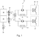
- FIG. 1 a transmission control 10 with a first reversing pump actuator 11 and a second reversing pump actuator 12 is shown in simplified form.
- the Reversierpumpenaktoren 11 and 12 are fluid pumps, as indicated by arrow symbols is, are operable in opposite directions.
- the Reversierpumpenaktoren 11 and 12 allow in a particularly advantageous manner, the operation of a dual clutch 20 and a gear actuator device 30th
- the dual clutch 20 includes a first partial clutch 21 and a second partial clutch 22.
- the first partial clutch 21 of the dual clutch 20 can be actuated by the first reversing pump actuator 11.
- the second partial clutch 22 of the dual clutch 20 can be actuated by the second reversing pump actuator 12.
- the gear actuator device 30 comprises a first gear actuator 31 and a second gear actuator 32.
- the first gear actuator 31 is used to represent a selection function of the transmission and is therefore also referred to as a selection actuator.
- the second gear actuator 32 is preferably used to represent a switching function of the transmission and is therefore also referred to as a switching actuator.
- a shift shaft 35 extends downwardly from the gear actuator 30 in the vertical direction.
- Each of the two reversing pump actuators 11, 12 is assigned an AND valve 41, 42.
- the AND valve 41, 42 is also referred to as a two-pressure valve and has two ports, with which the AND valve 41, 42 is connected to the respective terminals of the associated Reversierpumpenaktors 11, 12.
- the AND valve 41, 42 comprises a tank connection.
- the gear actuator device 30 is coupled via an OR valve 45 with the two reversing pump actuators 11, 12. This provides, inter alia, the advantage that the Reversierpumpenaktor 11, 12, which is currently not busy with the operation of its associated clutch 21, 22, the associated gear actuator 32, 31 can supply a flow rate and a delivery pressure.
- the two proportional directional control valves 51, 52 are connected between the OR valve 45 and the gear actuator device 30.
- the two proportional directional control valves 51, 52 are designed as 4/3-way valves and are actuated electromagnetically. By a spring device shown symbolically, the two proportional directional control valves 51, 52 in their illustrated Biased switch positions.
- the proportional directional control valve 51 is assigned to the selection actuator 31.
- the proportional directional control valve 52 is assigned to the switching actuator 32.
- FIGS. 2 and 3 is simplified, as the switch actuator 32 from FIG. 1 can be executed.
- the switching actuator is in the FIGS. 2 and 3 as a pivoting actuator 60; 70 executed.
- the pivot actuator 60; 70 has a reset function.
- Figure 2A; 3A is the Schwenkaktor 60; 70 shown in its relaxed position.
- FIGS. 2B; 3B is the Schwenkaktor 60; 70 shown in its cocked position.
- the pivot actuator 60 in FIG. 2 two return springs 61, 62.
- the pivoting actuator 60 includes a pivoting body 64 having a pivoting wing 65.
- the pivoting wing 65 with the pivoting body 64 is movable relative to a fixed wing 66 which is fixed to a stationary housing part of the pivoting actuator 60.
- illustrated pivoting actuator 70 comprises only one restoring spring 71.
- a pivoting body 74 is pivotable in a stationary housing part of the pivoting actuator 70 in a clockwise and counterclockwise direction. In this case, the return spring 71 is compressed, as can be seen in FIG. 3B sees.
- the swivel actuator 70 representing the switch actuator 32 can be actuated fluidically via a swivel blade 75.
- the swing vanes 75 of the Schwenkaktors 70 can be acted upon by the Reversierpumpenaktor 11 either from above or from below with fluid pressure.
- the switching shaft 35 can be rotated accordingly to illustrate the switching movement.
- FIG. 4 a transmission control 80 is shown, which is substantially the representation of FIG. 1 equivalent.
- the selection actuator 31 of the gear actuator device 30 is designed as a double-acting fluid cylinder 84.
- the double-acting fluid cylinder 84 is pressurized to select the gear via the proportional directional control valve 51 by the Reversierpumpenaktor 12 with fluid pressure.
- Transmission controls 90 are shown, in which the two proportional directional control valves 51, 52 by a common valve device 100; 110 replaced.
- the double-acting fluid cylinder 84 in FIGS. 5 and 6 is also replaced by a single-acting fluid cylinder 94.
- the single-acting fluid cylinder 94 serves to illustrate the selection function and is equipped with a return spring 95. As a result, the complexity of the necessary valve logic can be significantly reduced.
- the return spring 95 acts in the single-acting fluid cylinder 94 in the direction of Erdhiskraft.
- common valve device 100 is a 6/3-way valve with a center position for adjusting the Wählaktors 31 and two positions for adjusting the Wegaktors 32.
- center position of the single-acting fluid cylinder 94 is relieved of pressure on both sides.
- the return spring 95 acts together with the Erdhekraft on the switching shaft 35. This simplifies the control of the single-acting fluid cylinder 94 via the bidirectionally operated hydraulic pump, which represents the Reversierpumpenaktor 12.
- common valve device 110 is designed as a 6/5-way valve with a center position c, two positions a and e for adjusting the switching actuator 32 and two intermediate positions b and d.
- the intermediate positions b and d serve for the passive retraction of the shift rod 35 in its rest position.
- the intermediate positions b and d are subjected to highly dynamic, so that the adjusted dialing position is not left.
- FIG. 7 is indicated by means of symbols 111 and 112, that the common valve device 110 from FIG. 6 can be controlled directly electromagnetically.
- a symbolically indicated spring 112 the common valve device 110 in their in FIG. 6 biased with c center position.
- the symbol 111 represents, for example, an electromagnet acting directly on the valve logic.
- the common valve device 110 can also be fluidly controlled by a pilot valve 125.
- the pilot valve 125 is a proportional directional valve with an open position and a closed position.
- the pilot valve 125 is actuated electromagnetically and is biased in its illustrated open position.
- the common valve device 110 can also be designed as a rotary slide valve.
- the rotary valve valve is driven by a rotatable drive, for example via a stepper motor.
- FIG. 10 For example, a transmission controller 150 is shown in FIG. 5 similar. In contrast to FIG. 5 the common valve device (100 in FIG. 5 ) in FIG. 10 replaced by two identical switching valves 151, 152.
- the two identical switching valves 151, 152 are designed as 4/2-way valves.
- the two switching valves 151, 152 are actuated electromagnetically, as indicated by a corresponding symbol. By spring symbols is indicated that the two identical switching valves 151, 152 in their in FIG. 10 shown normal position are biased.
- both switching valves 151, 152 as shown, in their normal position, then the respective volume flow source, so the respective reversing pump 11,12, connected to the single-acting fluid cylinder 94, which is also referred to as a select piston.
- the respective reversing pump actuator 11, 12, also referred to as a pump is connected with one side of the gearbox actuator 32 to the swiveling body or swivel piston.
- a switching valve 151, 152 is provided for each direction of rotation.
- the transmission control 150 shown has the advantage that two relatively simple, identical switching valves 151, 152 are used. In addition, even in case of failure of one of the switching valves 151, 152 in both partial transmissions still gears are switched. The selection and switching positions are controlled via a fine control of the respective reversing pump actuator 11, 12.
Landscapes
- Engineering & Computer Science (AREA)
- General Engineering & Computer Science (AREA)
- Mechanical Engineering (AREA)
- Control Of Transmission Device (AREA)
- Gear-Shifting Mechanisms (AREA)
- Friction Gearing (AREA)
- Fluid-Pressure Circuits (AREA)
- Hydraulic Clutches, Magnetic Clutches, Fluid Clutches, And Fluid Joints (AREA)
Description
- Die Erfindung betrifft eine Getriebesteuerung zum fluidischen Betätigen eines Getriebes, das mehrere Gänge umfasst, die mit Hilfe einer Getriebeaktoreinrichtung gewählt und geschaltet werden können, und zum fluidischen Betätigen von zwei Teilkupplungen einer Doppelkupplung.
- Aus der deutschen Offenlegungsschrift
DE 10 2008 009 653 A1 , welche alle Merkmale des Oberbegriffs des Anspruchs 1 offenbart, ist eine Hydraulikanordnung zur Steuerung eines Doppelkupplungsgetriebes eines Kraftfahrzeugs bekannt, die umfasst: Eine hydraulische Energiequelle zur Versorgung der Hydraulikanordnung mittels eines Hydraulikmediums mit hydraulischer Energie; einen Druckspeicher zur Speicherung der hydraulischen Energie; eine Kupplungskühlung zur Kühlung von Kupplungen des Doppelkupplungsgetriebes mittels des Hydraulikmediums; Kupplungsaktoren zum Betätigen einer ersten Kupplung und einer zweiten Kupplung, wobei die hydraulische Energiequelle eine zweiflutige Elektropumpe umfasst. Aus der deutschen OffenlegungsschriftDE 10 2010 047 801 A1 ist ein Hydrostataktor mit einem Geberzylinder enthaltend ein Gehäuse und einen in dem Gehäuse axial verlagerbaren, eine mit Druckmittel befüllte Druckkammer mit Druck beaufschlagenden Kolben, mit einem einen Drehantrieb in eine Axialbewegung wandelnden Planetenwälzgetriebe mit einer Hülse bekannt, wobei das Planetenwälzgetriebe durch einen Elektromotor angetrieben ist. - Aufgabe der Erfindung ist es, das fluidische Betätigen eines Getriebes, das mehrere Gänge umfasst, die mit Hilfe einer Getriebeaktoreinrichtung gewählt und geschaltet werden können, und das fluidische Betätigen von zwei Teilkupplungen einer Doppelkupplung, zu vereinfachen. Die Aufgabe ist bei einer Getriebesteuerung zum fluidischen Betätigen eines Getriebes, das mehrere Gänge umfasst, die mit Hilfe einer Getriebeaktoreinrichtung gewählt und geschaltet werden, und zum fluidischen Betätigen von zwei Teilkupplungen einer Doppelkupplung, dadurch gelöst, dass die Getriebesteuerung zwei Reversierpumpenaktoren umfasst, denen jeweils eine der Teilkupplungen und jeweils ein UND-Ventil zugeordnet ist und die jeweils zwei Anschlüsse aufweisen, wobei an den jeweiligen Anschlüssen des zugeordneten Reversierpumpenaktors das fluidisches UND-Ventil angeschlossen ist, das als dritten Anschluss einen Tankanschluss aufweist, wobei die Getriebeaktoreinrichtung über ein fluidisches ODER-Ventil an die zwei Reversierpumpenaktoren angeschlossen ist. Bei den Reversierpumpenaktoren handelt es sich vorzugsweise um Fluidpumpen, die in entgegengesetzten Förderrichtungen betrieben werden können. Bei den Fluidpumpen handelt es sich insbesondere um Hydraulikpumpen, die mit einem Hydraulikmedium, wie Hydrauliköl, betrieben werden. Die Hydraulikpumpen sind vorzugsweise in Verdrängerbauweise ausgeführt. Die Hydraulikpumpen können als Flügelzellenpumpe, Zahnradpumpe oder Kolbenpumpe ausgeführt sein. Zum Antrieb der Reversierpumpenaktoren werden vorteilhaft Elektromotoren verwendet. In einer ersten Förderrichtung können die Reversierpumpenaktoren zum Beispiel verwendet werden, um eine der Teilkupplungen zu betätigen, insbesondere zu schließen. In einer zweiten Förderrichtung können die Reversierpumpenaktoren zum Beispiel verwendet werden, um einen Getriebeaktor der Getriebeaktoreinrichtung zu betätigen. Dabei dient einer der Getriebeaktoren vorteilhaft zum Wählen eines Gangs des Getriebes. Der andere Getriebeaktor dient vorteilhaft zum Schalten des gewählten Gangs. Die Getriebeaktoren, die zum Ausführen einer Wähl- und/oder Schaltbewegung dienen, werden auch als Gangsteller bezeichnet. Die Teilkupplungen der Doppelkupplung können direkt oder indirekt betätigt werden. Die Teilkupplungen können nass- oder trockenlaufend ausgeführt sein. Durch die erfindungsgemäße Kombination der beiden Reversierpumpenaktoren in der Getriebesteuerung mit den beiden UND-Ventilen und dem ODER-Ventil kann die Getriebesteuerung erheblich vereinfacht werden. Die UND-Ventile werden auch als Zweidruckventile bezeichnet und ermöglichen besonders vorteilhaft drehrichtungsunabhängig unterschiedliche Getriebefunktionen. Die UND-Ventile sind jeweils den Pumpenanschlüssen der Reversierpumpenaktoren zugeordnet. Durch das ODER-Ventil wird auf einfache Art und Weise ermöglicht, dass der jeweilige Reversierpumpenaktor, der gerade nicht mit der Betätigung einer zugeordneten Teilkupplung beschäftigt ist, den zugehörigen Getriebeaktor der Getriebeaktoreinrichtung mit einem Förderstrom und einem Förderdruck versorgen kann.
- Ein bevorzugtes Ausführungsbeispiel der Getriebesteuerung ist dadurch gekennzeichnet, dass die Getriebeaktoreinrichtung zum Darstellen der Schaltfunktion einen Schwenkaktor mit einer Rückstellfunktion umfasst. Zur Darstellung der Rückstellfunktion kann zum Beispiel eine Rückstellfedereinrichtung verwendet werden. Die Rückstellfedereinrichtung kann eine Rückstellfeder oder mehrere Rückstellfedern, zum Beispiel zwei Rückstellfedern, umfassen. Bei im Rahmen der vorliegenden Erfindung durchgeführten Untersuchungen wurde herausgefunden, dass es sich, insbesondere unter Dynamikgesichtspunkten, als vorteilhaft erweist, wenn der Schwenkaktor eine Rückstellfunktion aufweist.
- Ein weiteres bevorzugtes Ausführungsbeispiel der Getriebesteuerung ist dadurch gekennzeichnet, dass die Getriebeaktoreinrichtung zum Darstellen der Wählfunktion einen einfach wirkenden Fluidzylinder mit einer Rückstellfunktion umfasst. Die Rückstellfunktion wird zum Beispiel mit einer Rückstellfedereinrichtung dargestellt. Die Rückstellfedereinrichtung umfasst zum Beispiel eine Rückstellfeder, durch welche der einfach wirkende Fluidzylinder in eine Ausgangsstellung vorgespannt wird. Der einfach wirkende Fluidzylinder ersetzt vorteilhaft einen doppelwirkenden Fluidzylinder. Dadurch kann die Komplexität einer benötigten Ventillogik erheblich reduziert werden. Die Rückstellfedereinrichtung zur Darstellung der Rückstellfunktion wirkt vorzugsweise in Richtung der Erdschwerkraft.
- Ein weiteres bevorzugtes Ausführungsbeispiel der Getriebesteuerung ist dadurch gekennzeichnet, dass die Getriebeaktoreinrichtung einen Schaltaktor und einen Wählaktor umfasst, die durch eine gemeinsame Ventileinrichtung angesteuert sind. Bei dem Schaltaktor handelt es sich vorzugsweise um den vorab beschriebenen Schwenkaktor. Bei dem Wählaktor handelt es sich vorzugsweise um den vorab beschriebenen einfach wirkenden Fluidzylinder. Die gemeinsame Ventileinrichtung ist zum Beispiel als Wegeventil ausgeführt. Das Wegeventil kann als Längsschieberventil ausgeführt sein. Die gemeinsame Ventileinrichtung ist vorzugsweise in eine Mittelstellung vorgespannt, die zum Verstellen des Wählaktors dient.
- Ein weiteres bevorzugtes Ausführungsbeispiel der Getriebesteuerung ist dadurch gekennzeichnet, dass die gemeinsame Ventileinrichtung als 6/3-Wegeventil mit einer Mittelstellung zum Verstellen des Wählaktors und zwei Stellungen zum Verstellen des Schaltaktors ausgeführt ist. Dadurch kann auf einfache Art und Weise mit nur einer gemeinsamen Ventileinrichtung die Wählfunktion und die Schaltfunktion der Getriebeaktoreinrichtung dargestellt werden. Ein weiteres bevorzugtes Ausführungsbeispiel der Getriebesteuerung ist dadurch gekennzeichnet, dass die gemeinsame Ventileinrichtung als 6/5-Wegeventil mit einer Mittelstellung zum Verstellen des Wählaktors, zwei Stellungen zum Verstellen des Schaltaktors und zwei Zwischenstellungen ausgeführt ist. Die Zwischenstellungen ermöglichen auf einfache Art und Weise ein passives Zurücklaufen einer Schaltstange der Getriebeaktoreinrichtung in ihre Ruheposition. Bei einem Wechsel zwischen der Mittelstellung und den Stellungen zum Verstellen des Schaltaktors werden die Zwischenstellungen hochdynamisch durchlaufen, so dass eine eingeregelte Wählposition der Getriebeaktoreinrichtung nicht verlassen wird.
- Ein weiteres bevorzugtes Ausführungsbeispiel der Getriebesteuerung ist dadurch gekennzeichnet, dass die gemeinsame Ventileinrichtung direkt durch einen Elektromagneten betätigt wird. Das hat sich im Hinblick auf die Ventillogik der gemeinsamen Ventileinrichtung als vorteilhaft erwiesen.
- Ein weiteres bevorzugtes Ausführungsbeispiel der Getriebesteuerung ist dadurch gekennzeichnet, dass die gemeinsame Ventileinrichtung über ein Vorsteuerventil betätigt wird. Bei dem Vorsteuerventil handelt es sich zum Beispiel um ein als Proportionalventil ausgeführtes 2/2-Wegeventil, das zum Beispiel elektromagnetisch angesteuert wird.
- Ein weiteres bevorzugtes Ausführungsbeispiel der Getriebesteuerung ist dadurch gekennzeichnet, dass die gemeinsame Ventileinrichtung als Drehschieberventil ausgeführt ist. Das hat sich im Hinblick auf die Schaltdynamik der gemeinsamen Ventileinrichtung als vorteilhaft erwiesen.
- Ein weiteres bevorzugtes Ausführungsbeispiel der Getriebesteuerung ist dadurch gekennzeichnet, dass die gemeinsame Ventileinrichtung durch einen Drehantrieb angesteuert ist. Bei dem Drehantrieb der als Drehschieberventil ausgeführten gemeinsamen Ventileinrichtung handelt es sich zum Beispiel um einen Schrittmotor.
- Ein weiteres bevorzugtes Ausführungsbeispiel der Getriebesteuerung ist dadurch gekennzeichnet, dass die Getriebeaktoreinrichtung einen Schaltaktor und einen Wählaktor umfasst, die durch zwei baugleiche Proportional-Wegeventile angesteuert sind. Dadurch kann der Herstellaufwand weiter reduziert werden. Die baugleichen Proportional-Wegeventile sind zum Beispiel als 4/3-Wegeventile ausgeführt und werden vorzugsweise elektromagnetisch betätigt.
- Ein weiteres bevorzugtes Ausführungsbeispiel der Getriebesteuerung ist dadurch gekennzeichnet, dass die Getriebeaktoreinrichtung einen Schaltaktor und einen Wählaktor umfasst, die durch zwei baugleiche Schaltventile angesteuert sind. Dadurch kann der Herstellaufwand weiter reduziert werden. Die beiden baugleichen Schaltventile sind zum Beispiel als 4/2-Wegeventile ausgeführt.
- Die Erfindung betrifft gegebenenfalls auch ein Verfahren zum fluidischen Betätigen eines Getriebes, das mehrere Gänge umfasst, die mit Hilfe einer Getriebeaktoreinrichtung gewählt und geschaltet werden können, und zum fluidischen Betätigen von zwei Teilkupplungen einer Doppelkupplung mit einer vorab beschriebenen Getriebesteuerung.
- Weitere Vorteile, Merkmale und Einzelheiten der Erfindung ergeben sich aus der nachfolgenden Beschreibung, in der unter Bezugnahme auf die Zeichnung verschiedene Ausführungsbeispiele im Einzelnen beschrieben sind. Es zeigen:
-
Figur 1 eine vereinfachte Darstellung einer erfindungsgemäßen Getriebesteuerung mit zwei Reversierpumpenaktoren, die zur Betätigung einer Doppelkupplung und einer Getriebeaktoreinrichtung dienen; -
Figur 2A und 2B eine vereinfachte Darstellung eines Schwenkaktors mit zwei Rückstellfedern zur Darstellung einer Rückstellfunktion; -
Figur 3A und 3B einen ähnlichen Schwenkaktor wie inFigur 2 mit nur einer Rückstellfeder zur Darstellung der Rückstellfunktion; -
Figur 4 eine ähnliche Darstellung wie inFigur 1 mit einem Schwenkaktor zur Darstellung der Schaltfunktion und einem doppelwirkenden Fluidzylinder zur Darstellung der Wählfunktion des Getriebes; -
Figur 5 einen Ausschnitt ausFigur 4 mit einem einfachwirkenden Fluidzylinder zur Darstellung der Wählfunktion des Getriebes und mit einer gemeinsamen Ventileinrichtung zum Ansteuern der Getriebeaktoreinrichtung mit den beiden Getriebeaktoren; -
Figur 6 die gleiche Darstellung wie inFigur 5 mit einer anderen gemeinsamen Ventileinrichtung; -
Figur 7 die gemeinsame Ventileinrichtung ausFigur 6 alleine mit Ansteuersymbolen; -
Figur 8 die gemeinsame Ventileinrichtung ausFigur 6 alleine mit einem Vorsteuerventil; -
Figur 9 eine Ausführung der gemeinsamen Ventileinrichtung ausFigur 6 als Drehschieberventil und -
Figur 10 eine ähnliche Darstellung wie inFigur 5 mit zwei baugleichen Schaltventilen anstelle der gemeinsamen Ventileinrichtung. - In
Figur 1 ist eine Getriebesteuerung 10 mit einem ersten Reversierpumpenaktor 11 und einem zweiten Reversierpumpenaktor 12 vereinfacht dargestellt. Bei den Reversierpumpenaktoren 11 und 12 handelt es sich um Fluidpumpen, die, wie durch Pfeilsymbole angedeutet ist, in entgegengesetzten Förderrichtungen betreibbar sind. Die Reversierpumpenaktoren 11 und 12 ermöglichen auf besonders vorteilhafte Art und Weise die Betätigung einer Doppelkupplung 20 und einer Getriebeaktoreinrichtung 30. - Die Doppelkupplung 20 umfasst eine erste Teilkupplung 21 und eine zweite Teilkupplung 22. Die erste Teilkupplung 21 der Doppelkupplung 20 ist durch den ersten Reversierpumpenaktor 11 betätigbar. Die zweite Teilkupplung 22 der Doppelkupplung 20 ist durch den zweiten Reversierpumpenaktor 12 betätigbar.
- Die Getriebeaktoreinrichtung 30 umfasst einen ersten Getriebeaktor 31 und einen zweiten Getriebeaktor 32. Der erste Getriebeaktor 31 dient zur Darstellung einer Wählfunktion des Getriebes und wird daher auch als Wählaktor bezeichnet. Der zweite Getriebeaktor 32 dient vorzugsweise zur Darstellung einer Schaltfunktion des Getriebes und wird daher auch als Schaltaktor bezeichnet. Eine Schaltwelle 35 erstreckt sich von der Getriebeaktoreinrichtung 30 in vertikaler Richtung nach unten.
- Den beiden Reversierpumpenaktoren 11, 12 ist jeweils ein UND-Ventil 41, 42 zugeordnet. Das UND-Ventil 41, 42 wird auch als Zweidruckventil bezeichnet und hat zwei Anschlüsse, mit denen das UND-Ventil 41, 42 an die jeweiligen Anschlüsse des zugeordneten Reversierpumpenaktors 11, 12 angeschlossen ist. Als dritten Anschluss umfasst das UND-Ventil 41, 42 einen Tankanschluss.
- Durch das UND-Ventil 41, 42 oder Zweidruckventil wird auf einfache Art und Weise ermöglicht, dass mit den Reversierpumpenaktoren 11, 12 drehrichtungsunabhängig unterschiedliche Getriebefunktionen dargestellt werden können. Die Getriebeaktoreinrichtung 30 ist über ein ODER-Ventil 45 mit den beiden Reversierpumpenaktoren 11, 12 gekoppelt. Das liefert unter anderem den Vorteil, dass der Reversierpumpenaktor 11, 12, der gerade nicht mit der Betätigung seiner zugeordneten Kupplung 21, 22 beschäftigt ist, den zugeordneten Getriebeaktor 32, 31 mit einem Förderstrom und einem Förderdruck versorgen kann.
- Zwischen das ODER-Ventil 45 und die Getriebeaktoreinrichtung 30 sind zwei Proportional-Wegeventile 51, 52 geschaltet. Die beiden Proportional-Wegeventile 51, 52 sind als 4/3-Wegeventile ausgeführt und werden elektromagnetisch betätigt. Durch eine symbolisch dargestellte Federeinrichtung sind die beiden Proportional-Wegeventile 51, 52 in ihre dargestellten Schaltstellungen vorgespannt. Das Proportional-Wegeventil 51 ist dem Wählaktor 31 zugeordnet. Das Proportional-Wegeventil 52 ist dem Schaltaktor 32 zugeordnet.
- In den
Figuren 2 und 3 ist vereinfacht dargestellt, wie der Schaltaktor 32 ausFigur 1 ausgeführt sein kann. Der Schaltaktor ist in denFiguren 2 und 3 als Schwenkaktor 60; 70 ausgeführt. Der Schwenkaktor 60; 70 hat eine Rückstellfunktion. InFigur 2A; 3A ist der Schwenkaktor 60; 70 in seiner entspannten Stellung dargestellt. In denFiguren 2B; 3B ist der Schwenkaktor 60; 70 in seiner gespannten Stellung gezeigt. - Zur Darstellung der Rückstellfunktion umfasst der Schwenkaktor 60 in
Figur 2 zwei Rückstellfedern 61, 62. Der Schwenkaktor 60 umfasst einen Schwenkkörper 64 mit einem Schwenkflügel 65. Der Schwenkflügel 65 mit dem Schwenkkörper 64 ist relativ zu einem Festflügel 66 bewegbar, der an einem feststehenden Gehäuseteil des Schwenkaktors 60 befestigt ist. - In
Figur 2B sieht man, dass die Rückstellfeder 61 komprimiert wird, wenn der Schwenkkörper 64 mit dem Schwenkflügel 65 relativ zu dem Festflügel 66 gegen den Uhrzeigersinn verdreht wird. - Der in
Figur 3 dargestellte Schwenkaktor 70 umfasst im Unterschied zum vorangegangenen Ausführungsbeispiel nur eine Rückstellfeder 71. Ein Schwenkkörper 74 ist in einem feststehenden Gehäuseteil des Schwenkaktors 70 im Uhrzeigersinn und gegen den Uhrzeigersinn verschwenkbar. Dabei wird die Rückstellfeder 71 komprimiert, wie man inFigur 3B sieht. - In
Figur 4 sieht man, dass der den Schaltaktor 32 darstellende Schwenkaktor 70 über einen Schwenkflügel 75 fluidisch betätigbar ist. Über das Proportional-Wegeventil 52 kann der Schwenkflügel 75 des Schwenkaktors 70 durch den Reversierpumpenaktor 11 entweder von oben oder von unten mit Fluiddruck beaufschlagt werden. Dadurch kann die Schaltwelle 35 zur Darstellung der Schaltbewegung entsprechend verdreht werden. - In
Figur 4 ist eine Getriebesteuerung 80 dargestellt, die im Wesentlichen der Darstellung derFigur 1 entspricht. Der Wählaktor 31 der Getriebeaktoreinrichtung 30 ist als doppeltwirkender Fluidzylinder 84 ausgeführt. Der doppeltwirkende Fluidzylinder 84 wird zum Gangwählen über das Proportional-Wegeventil 51 durch den Reversierpumpenaktor 12 mit Fluiddruck beaufschlagt. - In den
Figuren 5 und6 sind Getriebesteuerungen 90 dargestellt, in denen die beiden Proportional-Wegeventile 51, 52 durch eine gemeinsame Ventileinrichtung 100; 110 ersetzt werden. In diesem Zusammenhang wird auch der doppeltwirkende Fluidzylinder 84 in den Figuren 5 und 6 durch einen einfachwirkenden Fluidzylinder 94 ersetzt. Der einfachwirkende Fluidzylinder 94 dient zur Darstellung der Wählfunktion und ist mit einer Rückstellfeder 95 ausgestattet. Dadurch kann die Komplexität der notwendigen Ventillogik erheblich reduziert werden. Die Rückstellfeder 95 wirkt in dem einfachwirkenden Fluidzylinder 94 in Richtung der Erdschwerkraft. - Bei der in
Figur 5 dargestellten gemeinsamen Ventileinrichtung 100 handelt es sich um ein 6/3-Wegeventil mit einer Mittelstellung zum Verstellen des Wählaktors 31 und zwei Stellungen zum Verstellen des Schaltaktors 32. In seiner dargestellten Mittelstellung ist der einfachwirkende Fluidzylinder 94 auf beiden Seiten von Druck entlastet. Die Rückstellfeder 95 wirkt zusammen mit der Erdschwerkraft auf die Schaltwelle 35. Dadurch wird die Ansteuerung des einfachwirkenden Fluidzylinders 94 über die bidirektional betriebene Hydraulikpumpe, die den Reversierpumpenaktor 12 darstellt, vereinfacht. - Die in
Figur 6 dargestellte gemeinsame Ventileinrichtung 110 ist als 6/5-Wegeventil mit einer Mittelstellung c, zwei Stellungen a und e zum Verstellen des Schaltaktors 32 und zwei Zwischenstellungen b und d ausgeführt. Die Zwischenstellungen b und d dienen dem passiven Zurücklaufen der Schaltstange 35 in ihre Ruheposition. Beim Wechsel zwischen Wählen und Schalten werden die Zwischenstellungen b und d hochdynamisch durchlaufen, so dass die eingeregelte Wählposition nicht verlassen wird. - In
Figur 7 ist mit Hilfe von Symbolen 111 und 112 angedeutet, dass die gemeinsame Ventileinrichtung 110 ausFigur 6 direkt elektromagnetisch angesteuert werden kann. Durch eine symbolisch angedeutete Feder 112 ist die gemeinsame Ventileinrichtung 110 in ihre inFigur 6 mit c bezeichnete Mittelstellung vorgespannt. Das Symbol 111 stellt zum Beispiel einen direkt auf die Ventillogik wirkenden Elektromagneten dar. - In
Figur 8 ist mit Hilfe von Symbolen 121 und 122 dargestellt, dass die gemeinsame Ventileinrichtung 110 auch durch ein Vorsteuerventil 125 fluidisch angesteuert werden kann. Bei dem Vorsteuerventil 125 handelt es sich um ein Proportional-Wegeventil mit einer Öffnungsstellung und einer Schließstellung. Das Vorsteuerventil 125 wird elektromagnetisch angesteuert und ist in seine dargestellte Öffnungsstellung vorgespannt. - In
Figur 9 ist dargestellt, dass die gemeinsame Ventileinrichtung 110 auch als Drehschieberventil ausgeführt sein kann. Der Antrieb des Drehschieberventils erfolgt über einen drehfähigen Antrieb, zum Beispiel über einen Schrittmotor. - In
Figur 10 ist eine Getriebesteuerung 150 dargestellt, die der Getriebesteuerung 90 inFigur 5 ähnelt. Im Unterschied zuFigur 5 wurde die gemeinsame Ventileinrichtung (100 inFigur 5 ) inFigur 10 durch zwei baugleiche Schaltventile 151, 152 ersetzt. - Die beiden baugleichen Schaltventile 151, 152 sind als 4/2-Wegeventile ausgeführt. Die beiden Schaltventile 151, 152 werden elektromagnetisch betätigt, wie durch ein entsprechendes Symbol angedeutet ist. Durch Federsymbole ist angedeutet, dass die beiden baugleichen Schaltventile 151, 152 in ihre in
Figur 10 dargestellte Normalstellung vorgespannt sind. - Sind beide Schaltventile 151, 152, wie dargestellt, in ihrer Normalstellung, so ist die jeweilige Volumenstromquelle, also der jeweilige Reversierpumpenaktor 11,12, mit dem einfach wirkenden Fluidzylinder 94 verbunden, der auch als Wähl-Kolben bezeichnet wird.
- Wird eines der Schaltventile 151, 152 betätigt, so wird der jeweilige auch als Pumpe bezeichnete Reversierpumpenaktor 11, 12 mit jeweils einer Seite des Getriebeaktors 32 mit dem Schwenkkörper beziehungsweise Schwenkkolben verbunden. Für jede Drehrichtung ist ein Schaltventil 151, 152 vorgesehen.
- Die in
Figur 10 dargestellte Getriebesteuerung 150 hat zum einen den Vorteil, dass zwei relativ einfache, baugleiche Schaltventile 151, 152 verwendet werden. Darüber hinaus können auch bei Ausfall eines der Schaltventile 151, 152 in beiden Teilgetrieben noch Gänge geschaltet werden. Die Ansteuerung der Wähl- und Schaltpositionen erfolgt über eine Feinsteuerung des jeweiligen Reversierpumpenaktors 11, 12. -
- 10 Getriebesteuerung
- 11 Reversierpumpenaktor
- 12 Reversierpumpenaktor
- 20 Doppelkupplung
- 21 Teilkupplung
- 22 Teilkupplung
- 30 Getriebeaktoreinrichtung
- 31 Getriebeaktor
- 32 Getriebeaktor
- 35 Schaltwelle
- 41 UND-Ventil
- 42 UND-Ventil
- 45 ODER-Ventil
- 51 Proportional-Wegeventil
- 52 Proportional-Wegeventil
- 60 Schwenkaktor
- 61 Rückschlagfeder
- 62 Rückschlagfeder
- 64 Schwenkkörper
- 65 Schwenkflügel
- 66 Festflügel
- 70 Schwenkaktor
- 71 Rückstellfeder
- 74 Schwenkkörper
- 75 Schwenkflügel
- 80 Getriebesteuerung
- 84 Doppeltwirkender Fluidzylinder
- 90 Getriebesteuerung
- 94 Einfachwirkender Fluidzylinder
- 95 Rückstellfeder
- 100 gemeinsame Ventileinrichtung
- 110 gemeinsame Ventileinrichtung
- 111 Symbol
- 112 Symbol
- 121 Symbol
- 122 Symbol
- 125 Vorsteuerventil
- 150 Getriebesteuerung
- 151 Schaltventil
- 152 Schaltventil
Claims (12)
- Getriebesteuerung (10;80;90) zum fluidischen Betätigen eines Getriebes, das mehrere Gänge umfasst, die mit Hilfe einer Getriebeaktoreinrichtung (30) gewählt und geschaltet werden, und zum fluidischen Betätigen von zwei Teilkupplungen (21,22) einer Doppelkupplung (20), dadurch gekennzeichnet, dass die Getriebesteuerung (10;80;90) zwei Reversierpumpenaktoren (11,12) umfasst, denen jeweils eine der Teilkupplungen (21,22) und jeweils ein UND-Ventil (41, 42) zugeordnet ist und die jeweils zwei Anschlüsse aufweisen, wobei an den jeweiligen Anschlüssen des zugeordneten Reversierpumpenaktors (11, 12) das fluidische UND-Ventil (41,42) angeschlossen ist, das als dritten Anschluss einen Tankanschluss aufweist, wobei die Getriebeaktoreinrichtung (30) über ein fluidisches ODER-Ventil (45) an die zwei Reversierpumpenaktoren (11,12) angeschlossen ist.
- Getriebesteuerung nach Anspruch 1, dadurch gekennzeichnet, dass die Getriebeaktoreinrichtung (30) zum Darstellen der Schaltfunktion einen Schwenkaktor (70) mit einer Rückstellfunktion umfasst.
- Getriebesteuerung nach einem der vorhergehenden Ansprüche, dadurch gekennzeichnet, dass die Getriebeaktoreinrichtung (30) zum Darstellen der Wählfunktion einen einfachwirkenden Fluidzylinder (94) mit einer Rückstellfunktion umfasst.
- Getriebesteuerung nach einem der vorhergehenden Ansprüche, dadurch gekennzeichnet, dass die Getriebeaktoreinrichtung (30) einen Schaltaktor (32) und einen Wählaktor (31) umfasst, die durch eine gemeinsame Ventileinrichtung (100;110) angesteuert sind.
- Getriebesteuerung nach Anspruch 4, dadurch gekennzeichnet, dass die gemeinsame Ventileinrichtung (100) als 6/3-Wegeventil mit einer Mittelstellung zum Verstellen des Wählaktors (31) und zwei Stellungen zum Verstellen des Schaltaktors (32) ausgeführt ist.
- Getriebesteuerung nach Anspruch 4, dadurch gekennzeichnet, dass die gemeinsame Ventileinrichtung (110) als 6/5-Wegeventil mit einer Mittelstellung (c) zum Verstellen des Wählaktors (31), zwei Stellungen (a,e) zum Verstellen des Schaltaktors (32) und zwei Zwischenstellungen (b,d) ausgeführt ist.
- Getriebesteuerung nach einem der Ansprüche 4 bis 6, dadurch gekennzeichnet, dass die gemeinsame Ventileinrichtung (100; 110) direkt durch einen Elektromagneten betätigt wird.
- Getriebesteuerung nach einem der Ansprüche 4 bis 6, dadurch gekennzeichnet, dass die gemeinsame Ventileinrichtung (100;110) über ein Vorsteuerventil (125) betätigt wird.
- Getriebesteuerung nach einem der Ansprüche 4 bis 8, dadurch gekennzeichnet, dass die gemeinsame Ventileinrichtung (100;110) als Drehschieberventil ausgeführt ist.
- Getriebesteuerung nach Anspruch 9, dadurch gekennzeichnet, dass die gemeinsame Ventileinrichtung (100;110) durch einen Drehantrieb angesteuert ist.
- Getriebesteuerung nach einem der Ansprüche 1 bis 3, dadurch gekennzeichnet, dass die Getriebeaktoreinrichtung (30) einen Schaltaktor (32) und einen Wählaktor (31) umfasst, die durch zwei baugleiche Proportional-Wegeventile (52;51) angesteuert sind.
- Getriebesteuerung nach einem der Ansprüche 1 bis 3, dadurch gekennzeichnet, dass die Getriebeaktoreinrichtung (30) einen Schaltaktor (32) und einen Wählaktor (31) umfasst, die durch zwei baugleiche Schaltventile (152; 151) angesteuert sind.
Applications Claiming Priority (2)
| Application Number | Priority Date | Filing Date | Title |
|---|---|---|---|
| DE102014206194 | 2014-04-01 | ||
| PCT/DE2015/200162 WO2015149778A1 (de) | 2014-04-01 | 2015-03-16 | Getriebesteuerung |
Publications (2)
| Publication Number | Publication Date |
|---|---|
| EP3126716A1 EP3126716A1 (de) | 2017-02-08 |
| EP3126716B1 true EP3126716B1 (de) | 2018-05-16 |
Family
ID=52875366
Family Applications (1)
| Application Number | Title | Priority Date | Filing Date |
|---|---|---|---|
| EP15716732.1A Active EP3126716B1 (de) | 2014-04-01 | 2015-03-16 | Getriebesteuerung |
Country Status (7)
| Country | Link |
|---|---|
| US (1) | US10295051B2 (de) |
| EP (1) | EP3126716B1 (de) |
| JP (1) | JP6629229B2 (de) |
| KR (1) | KR102345868B1 (de) |
| CN (1) | CN106164541B (de) |
| DE (1) | DE112015001613A5 (de) |
| WO (1) | WO2015149778A1 (de) |
Families Citing this family (21)
| Publication number | Priority date | Publication date | Assignee | Title |
|---|---|---|---|---|
| DE102015225090A1 (de) * | 2015-12-14 | 2017-06-14 | Schaeffler Technologies AG & Co. KG | Betätigungsmodul für eine hydraulisch betätigte Kupplungsaktuierung |
| DE102016203629A1 (de) | 2016-03-07 | 2017-09-07 | Schaeffler Technologies AG & Co. KG | Fluidanordnung |
| DE102016208336A1 (de) | 2016-05-13 | 2017-11-16 | Schaeffler Technologies AG & Co. KG | Fluidanordnung |
| DE102016210400B3 (de) * | 2016-06-13 | 2017-09-21 | Schaeffler Technologies AG & Co. KG | Fluidanordnung und Verfahren zur fluidischen Betätigung mindestens eines Verbrauchers |
| DE102016213318A1 (de) | 2016-07-21 | 2018-01-25 | Schaeffler Technologies AG & Co. KG | Verfahren zur Aufrechterhaltung eines Druckniveaus einer Hydraulikflüssigkeit in einer hydraulischen Aktoranordnung |
| DE102016220964A1 (de) * | 2016-10-25 | 2018-04-26 | Schaeffler Technologies AG & Co. KG | Hydraulikkreislauf für einen Hybridantriebsstrang |
| DE102016223537A1 (de) | 2016-11-28 | 2018-05-30 | Schaeffler Technologies AG & Co. KG | Fluidanordnung |
| DE102016223741A1 (de) | 2016-11-30 | 2018-05-30 | Schaeffler Technologies AG & Co. KG | Fluidanordnung |
| DE102017109361A1 (de) | 2017-05-02 | 2018-11-08 | Schaeffler Technologies AG & Co. KG | Aktuatoranordnung für ein Kraftfahrzeuggetriebe |
| DE102017004575A1 (de) * | 2017-05-12 | 2018-11-15 | Wabco Gmbh | Wähl- und Schaltvorrichtung für ein automatisiertes Stirnrad-Schaltgetriebe |
| DE102017115068A1 (de) * | 2017-07-06 | 2019-01-10 | Schaeffler Technologies AG & Co. KG | Verfahren und Fluidsystem zum fluidischen Betätigen von zwei Teilkupplungen |
| DE102017115069B4 (de) * | 2017-07-06 | 2019-11-21 | Schaeffler Technologies AG & Co. KG | Svstempack aus elektrischem Getriebeaktor, elektrischem Pumpenaktor und Ventilplatte und System aus Systempack und Getriebeqlocke mit einem Getriebeaktor mit axial qeteiltem Betätiqunqsmechanismus |
| DE102017115453A1 (de) * | 2017-07-11 | 2019-01-17 | Schaeffler Technologies AG & Co. KG | Verfahren und System zum fluidischen Betätigen von zwei Teilkupplungen |
| DE102017118061A1 (de) | 2017-08-09 | 2019-02-14 | Schaeffler Technologies AG & Co. KG | Fluidanordnung |
| DE102018106494A1 (de) | 2018-03-20 | 2019-09-26 | Schaeffler Technologies AG & Co. KG | Hydraulischer Gangaktor |
| DE102018214435A1 (de) * | 2018-08-27 | 2020-02-27 | Zf Friedrichshafen Ag | Hydrauliksystem zur Betätigung einer Mehrzahl von doppeltwirkenden Aktuatoren eines Getriebes |
| DE102018130700B4 (de) * | 2018-12-03 | 2020-07-02 | Schaeffler Technologies AG & Co. KG | Verfahren zum Herstellen einer hydraulischen Bereitschaft eines Hydrauliksystems sowie Hydrauliksystem |
| KR20200080656A (ko) * | 2018-12-27 | 2020-07-07 | 현대트랜시스 주식회사 | Dct용 클러치 액추에이터 |
| DE102019125519A1 (de) | 2019-09-23 | 2021-03-25 | Schaeffler Technologies AG & Co. KG | Betätigungseinrichtung mit Kupplungsaktor und integrierter Kühlmittelpumpfunktion |
| DE102021100272A1 (de) | 2021-01-11 | 2022-07-14 | Schaeffler Technologies AG & Co. KG | Verfahren zum Betätigen einer Abkoppeleinheit |
| DE102021100271A1 (de) | 2021-01-11 | 2022-07-14 | Schaeffler Technologies AG & Co. KG | Verfahren zum Betätigen einer Abkoppeleinheit |
Family Cites Families (15)
| Publication number | Priority date | Publication date | Assignee | Title |
|---|---|---|---|---|
| JPS58170955A (ja) * | 1982-03-31 | 1983-10-07 | Isuzu Motors Ltd | 変速機のアクチユエ−タ |
| DE4117736C1 (de) * | 1991-05-30 | 1992-05-21 | Mercedes-Benz Aktiengesellschaft, 7000 Stuttgart, De | |
| DE19900852A1 (de) | 1998-01-16 | 1999-07-22 | Atlas Fahrzeugtechnik Gmbh | Getriebe mit einer Einrichtung zur Betätigung des Drehmomentenübertragungssystems und der Getriebebetätigungselemente |
| GB2372080B (en) * | 2001-02-12 | 2004-09-29 | Luk Lamellen & Kupplungsbau | Hydraulic actuation systems |
| DE10143833B4 (de) * | 2001-09-07 | 2013-06-06 | Zf Friedrichshafen Ag | Kupplungssystem in einem Antriebsstrang zwischen einer Antriebseinheit und einem Getriebe |
| EP1767825B1 (de) * | 2005-09-22 | 2011-04-13 | Getrag Ford Transmissions GmbH | Hydraulische Steuerungsvorrichtung für ein automatisiertes Doppelkupplungsgetriebe |
| DE112007002509B4 (de) * | 2006-10-30 | 2016-12-08 | Schaeffler Technologies AG & Co. KG | Hydraulische Steuerung für ein Doppelkupplungsgetriebe |
| WO2008106927A1 (de) | 2007-03-07 | 2008-09-12 | Luk Lamellen Und Kupplungsbau Beteiligungs Kg | Hydraulikanordnung zur steuerung eines doppelkupplungsgetriebes eines kraftfahrzeuges |
| WO2011050767A1 (de) | 2009-10-29 | 2011-05-05 | Schaeffler Technologies Gmbh & Co. Kg | Hydrostataktor |
| DE102011100802A1 (de) * | 2011-05-06 | 2012-11-08 | Audi Ag | Verfahren zum Betreiben eines Kupplungsgetriebes, Kupplungsgetriebe |
| DE102011102277B4 (de) | 2011-05-23 | 2017-03-23 | Getrag Getriebe- Und Zahnradfabrik Hermann Hagenmeyer Gmbh & Cie Kg | Antriebsstrang für ein Kraftfahrzeug |
| JP5702228B2 (ja) * | 2011-05-31 | 2015-04-15 | 本田技研工業株式会社 | 変速機の油圧供給装置 |
| DE102012010172A1 (de) * | 2012-05-15 | 2013-11-21 | Getrag Getriebe- Und Zahnradfabrik Hermann Hagenmeyer Gmbh & Cie Kg | Aktuatoranordnung für einen Kraftfahrzeug-Antriebsstrang |
| US9803702B2 (en) | 2012-07-03 | 2017-10-31 | Fte Automotive Gmbh | Hydraulic actuating device for actuation of at least one friction clutch and at least one gear setting element in a motor vehicle |
| DE102013000157B3 (de) * | 2013-01-09 | 2014-01-23 | Fte Automotive Gmbh | Hydraulische Betätigungsvorrichtung für die Betätigung wenigstens einer Reibkupplung und wenigstens eines Getriebestellglieds in einem Kraftfahrzeug |
-
2015
- 2015-03-16 KR KR1020167026974A patent/KR102345868B1/ko active IP Right Grant
- 2015-03-16 WO PCT/DE2015/200162 patent/WO2015149778A1/de active Application Filing
- 2015-03-16 DE DE112015001613.9T patent/DE112015001613A5/de not_active Withdrawn
- 2015-03-16 JP JP2016560354A patent/JP6629229B2/ja not_active Expired - Fee Related
- 2015-03-16 EP EP15716732.1A patent/EP3126716B1/de active Active
- 2015-03-16 CN CN201580017424.1A patent/CN106164541B/zh active Active
- 2015-03-16 US US15/127,951 patent/US10295051B2/en not_active Expired - Fee Related
Non-Patent Citations (1)
| Title |
|---|
| None * |
Also Published As
| Publication number | Publication date |
|---|---|
| CN106164541A (zh) | 2016-11-23 |
| JP2017517688A (ja) | 2017-06-29 |
| DE112015001613A5 (de) | 2016-12-15 |
| JP6629229B2 (ja) | 2020-01-15 |
| KR20160140669A (ko) | 2016-12-07 |
| KR102345868B1 (ko) | 2022-01-03 |
| CN106164541B (zh) | 2018-04-13 |
| US20170037960A1 (en) | 2017-02-09 |
| US10295051B2 (en) | 2019-05-21 |
| WO2015149778A1 (de) | 2015-10-08 |
| EP3126716A1 (de) | 2017-02-08 |
Similar Documents
| Publication | Publication Date | Title |
|---|---|---|
| EP3126716B1 (de) | Getriebesteuerung | |
| EP3084273B1 (de) | Fluidanordnung | |
| EP2382402B1 (de) | Hydraulische steuerung für ein automatisiertes getriebe | |
| EP2754911B1 (de) | Hydraulische Betätigungsvorrichtung für die Betätigung wenigstens einer Reibkupplung und wenigstens eines Getriebestellglieds in einem Kraftfahrzeug | |
| DE102012200202B4 (de) | Hydraulische Schaltvorrichtung für ein Automatikgetriebe | |
| WO2015067259A1 (de) | Fluidanordnung | |
| DE102011105648A1 (de) | Hydraulische Betätigungsvorrichtung für die Betätigung von Kupplungen in insbesondere einem Mehrkupplungsgetriebe für Kraftfahrzeuge | |
| DE102015214998A1 (de) | Betätigungsanordnung | |
| DE102016217381A1 (de) | Fluidanordnung zum fluidischen Betätigen von Kraftfahrzeugkomponenten | |
| WO2017054815A1 (de) | Fluidanordnung | |
| DE102015211305B3 (de) | Druckabhängig einlegbare Parksperre für hydraulisches Schaltgetriebe | |
| WO2015021981A1 (de) | Fluidanordnung | |
| EP2647883B1 (de) | Hydraulische Steuerungsvorrichtung | |
| DE102015212101A1 (de) | Hydrauliksteuerung für einen Aktuator in einem Fahrzeuggetriebe | |
| DE102016216264A1 (de) | Fluidanordnung zum Betätigen von Fahrzeugkomponenten | |
| EP3126699B1 (de) | Kupplungsbetätigungsvorrichtung | |
| DE102012012977A1 (de) | Hydraulischer Antrieb | |
| DE102015208653A1 (de) | Fluidanordnung | |
| DE102014216714A1 (de) | Vorrichtung und Verfahren zum Betätigen von Stelleinheiten | |
| DE102014215517A1 (de) | Fluidanordnung | |
| WO2011072639A1 (de) | Hydraulikanordnung | |
| DE102016206017A1 (de) | Hydraulische Schaltelementanordnung | |
| DE102015225301A1 (de) | Hydraulische Betätigung einer Kupplung | |
| DE102016206015A1 (de) | Hydraulische Schaltelementanordnung | |
| DE102016223537A1 (de) | Fluidanordnung |
Legal Events
| Date | Code | Title | Description |
|---|---|---|---|
| STAA | Information on the status of an ep patent application or granted ep patent |
Free format text: STATUS: THE INTERNATIONAL PUBLICATION HAS BEEN MADE |
|
| PUAI | Public reference made under article 153(3) epc to a published international application that has entered the european phase |
Free format text: ORIGINAL CODE: 0009012 |
|
| STAA | Information on the status of an ep patent application or granted ep patent |
Free format text: STATUS: REQUEST FOR EXAMINATION WAS MADE |
|
| 17P | Request for examination filed |
Effective date: 20161102 |
|
| AK | Designated contracting states |
Kind code of ref document: A1 Designated state(s): AL AT BE BG CH CY CZ DE DK EE ES FI FR GB GR HR HU IE IS IT LI LT LU LV MC MK MT NL NO PL PT RO RS SE SI SK SM TR |
|
| AX | Request for extension of the european patent |
Extension state: BA ME |
|
| DAV | Request for validation of the european patent (deleted) | ||
| DAX | Request for extension of the european patent (deleted) | ||
| GRAP | Despatch of communication of intention to grant a patent |
Free format text: ORIGINAL CODE: EPIDOSNIGR1 |
|
| STAA | Information on the status of an ep patent application or granted ep patent |
Free format text: STATUS: GRANT OF PATENT IS INTENDED |
|
| INTG | Intention to grant announced |
Effective date: 20171208 |
|
| GRAS | Grant fee paid |
Free format text: ORIGINAL CODE: EPIDOSNIGR3 |
|
| GRAA | (expected) grant |
Free format text: ORIGINAL CODE: 0009210 |
|
| STAA | Information on the status of an ep patent application or granted ep patent |
Free format text: STATUS: THE PATENT HAS BEEN GRANTED |
|
| AK | Designated contracting states |
Kind code of ref document: B1 Designated state(s): AL AT BE BG CH CY CZ DE DK EE ES FI FR GB GR HR HU IE IS IT LI LT LU LV MC MK MT NL NO PL PT RO RS SE SI SK SM TR |
|
| REG | Reference to a national code |
Ref country code: GB Ref legal event code: FG4D Free format text: NOT ENGLISH |
|
| REG | Reference to a national code |
Ref country code: CH Ref legal event code: EP |
|
| REG | Reference to a national code |
Ref country code: IE Ref legal event code: FG4D Free format text: LANGUAGE OF EP DOCUMENT: GERMAN |
|
| REG | Reference to a national code |
Ref country code: DE Ref legal event code: R096 Ref document number: 502015004304 Country of ref document: DE |
|
| REG | Reference to a national code |
Ref country code: AT Ref legal event code: REF Ref document number: 999889 Country of ref document: AT Kind code of ref document: T Effective date: 20180615 |
|
| REG | Reference to a national code |
Ref country code: NL Ref legal event code: MP Effective date: 20180516 |
|
| REG | Reference to a national code |
Ref country code: LT Ref legal event code: MG4D |
|
| PG25 | Lapsed in a contracting state [announced via postgrant information from national office to epo] |
Ref country code: ES Free format text: LAPSE BECAUSE OF FAILURE TO SUBMIT A TRANSLATION OF THE DESCRIPTION OR TO PAY THE FEE WITHIN THE PRESCRIBED TIME-LIMIT Effective date: 20180516 Ref country code: LT Free format text: LAPSE BECAUSE OF FAILURE TO SUBMIT A TRANSLATION OF THE DESCRIPTION OR TO PAY THE FEE WITHIN THE PRESCRIBED TIME-LIMIT Effective date: 20180516 Ref country code: NO Free format text: LAPSE BECAUSE OF FAILURE TO SUBMIT A TRANSLATION OF THE DESCRIPTION OR TO PAY THE FEE WITHIN THE PRESCRIBED TIME-LIMIT Effective date: 20180816 Ref country code: BG Free format text: LAPSE BECAUSE OF FAILURE TO SUBMIT A TRANSLATION OF THE DESCRIPTION OR TO PAY THE FEE WITHIN THE PRESCRIBED TIME-LIMIT Effective date: 20180816 Ref country code: SE Free format text: LAPSE BECAUSE OF FAILURE TO SUBMIT A TRANSLATION OF THE DESCRIPTION OR TO PAY THE FEE WITHIN THE PRESCRIBED TIME-LIMIT Effective date: 20180516 Ref country code: FI Free format text: LAPSE BECAUSE OF FAILURE TO SUBMIT A TRANSLATION OF THE DESCRIPTION OR TO PAY THE FEE WITHIN THE PRESCRIBED TIME-LIMIT Effective date: 20180516 |
|
| PG25 | Lapsed in a contracting state [announced via postgrant information from national office to epo] |
Ref country code: HR Free format text: LAPSE BECAUSE OF FAILURE TO SUBMIT A TRANSLATION OF THE DESCRIPTION OR TO PAY THE FEE WITHIN THE PRESCRIBED TIME-LIMIT Effective date: 20180516 Ref country code: GR Free format text: LAPSE BECAUSE OF FAILURE TO SUBMIT A TRANSLATION OF THE DESCRIPTION OR TO PAY THE FEE WITHIN THE PRESCRIBED TIME-LIMIT Effective date: 20180817 Ref country code: LV Free format text: LAPSE BECAUSE OF FAILURE TO SUBMIT A TRANSLATION OF THE DESCRIPTION OR TO PAY THE FEE WITHIN THE PRESCRIBED TIME-LIMIT Effective date: 20180516 Ref country code: RS Free format text: LAPSE BECAUSE OF FAILURE TO SUBMIT A TRANSLATION OF THE DESCRIPTION OR TO PAY THE FEE WITHIN THE PRESCRIBED TIME-LIMIT Effective date: 20180516 Ref country code: NL Free format text: LAPSE BECAUSE OF FAILURE TO SUBMIT A TRANSLATION OF THE DESCRIPTION OR TO PAY THE FEE WITHIN THE PRESCRIBED TIME-LIMIT Effective date: 20180516 |
|
| PG25 | Lapsed in a contracting state [announced via postgrant information from national office to epo] |
Ref country code: SK Free format text: LAPSE BECAUSE OF FAILURE TO SUBMIT A TRANSLATION OF THE DESCRIPTION OR TO PAY THE FEE WITHIN THE PRESCRIBED TIME-LIMIT Effective date: 20180516 Ref country code: RO Free format text: LAPSE BECAUSE OF FAILURE TO SUBMIT A TRANSLATION OF THE DESCRIPTION OR TO PAY THE FEE WITHIN THE PRESCRIBED TIME-LIMIT Effective date: 20180516 Ref country code: CZ Free format text: LAPSE BECAUSE OF FAILURE TO SUBMIT A TRANSLATION OF THE DESCRIPTION OR TO PAY THE FEE WITHIN THE PRESCRIBED TIME-LIMIT Effective date: 20180516 Ref country code: PL Free format text: LAPSE BECAUSE OF FAILURE TO SUBMIT A TRANSLATION OF THE DESCRIPTION OR TO PAY THE FEE WITHIN THE PRESCRIBED TIME-LIMIT Effective date: 20180516 Ref country code: DK Free format text: LAPSE BECAUSE OF FAILURE TO SUBMIT A TRANSLATION OF THE DESCRIPTION OR TO PAY THE FEE WITHIN THE PRESCRIBED TIME-LIMIT Effective date: 20180516 Ref country code: EE Free format text: LAPSE BECAUSE OF FAILURE TO SUBMIT A TRANSLATION OF THE DESCRIPTION OR TO PAY THE FEE WITHIN THE PRESCRIBED TIME-LIMIT Effective date: 20180516 |
|
| REG | Reference to a national code |
Ref country code: DE Ref legal event code: R097 Ref document number: 502015004304 Country of ref document: DE |
|
| PG25 | Lapsed in a contracting state [announced via postgrant information from national office to epo] |
Ref country code: SM Free format text: LAPSE BECAUSE OF FAILURE TO SUBMIT A TRANSLATION OF THE DESCRIPTION OR TO PAY THE FEE WITHIN THE PRESCRIBED TIME-LIMIT Effective date: 20180516 Ref country code: IT Free format text: LAPSE BECAUSE OF FAILURE TO SUBMIT A TRANSLATION OF THE DESCRIPTION OR TO PAY THE FEE WITHIN THE PRESCRIBED TIME-LIMIT Effective date: 20180516 |
|
| PLBE | No opposition filed within time limit |
Free format text: ORIGINAL CODE: 0009261 |
|
| STAA | Information on the status of an ep patent application or granted ep patent |
Free format text: STATUS: NO OPPOSITION FILED WITHIN TIME LIMIT |
|
| 26N | No opposition filed |
Effective date: 20190219 |
|
| PG25 | Lapsed in a contracting state [announced via postgrant information from national office to epo] |
Ref country code: SI Free format text: LAPSE BECAUSE OF FAILURE TO SUBMIT A TRANSLATION OF THE DESCRIPTION OR TO PAY THE FEE WITHIN THE PRESCRIBED TIME-LIMIT Effective date: 20180516 |
|
| PG25 | Lapsed in a contracting state [announced via postgrant information from national office to epo] |
Ref country code: MC Free format text: LAPSE BECAUSE OF FAILURE TO SUBMIT A TRANSLATION OF THE DESCRIPTION OR TO PAY THE FEE WITHIN THE PRESCRIBED TIME-LIMIT Effective date: 20180516 |
|
| REG | Reference to a national code |
Ref country code: CH Ref legal event code: PL |
|
| GBPC | Gb: european patent ceased through non-payment of renewal fee |
Effective date: 20190316 |
|
| PG25 | Lapsed in a contracting state [announced via postgrant information from national office to epo] |
Ref country code: LU Free format text: LAPSE BECAUSE OF NON-PAYMENT OF DUE FEES Effective date: 20190316 Ref country code: AL Free format text: LAPSE BECAUSE OF FAILURE TO SUBMIT A TRANSLATION OF THE DESCRIPTION OR TO PAY THE FEE WITHIN THE PRESCRIBED TIME-LIMIT Effective date: 20180516 |
|
| REG | Reference to a national code |
Ref country code: BE Ref legal event code: MM Effective date: 20190331 |
|
| PG25 | Lapsed in a contracting state [announced via postgrant information from national office to epo] |
Ref country code: LI Free format text: LAPSE BECAUSE OF NON-PAYMENT OF DUE FEES Effective date: 20190331 Ref country code: GB Free format text: LAPSE BECAUSE OF NON-PAYMENT OF DUE FEES Effective date: 20190316 Ref country code: IE Free format text: LAPSE BECAUSE OF NON-PAYMENT OF DUE FEES Effective date: 20190316 Ref country code: CH Free format text: LAPSE BECAUSE OF NON-PAYMENT OF DUE FEES Effective date: 20190331 |
|
| PG25 | Lapsed in a contracting state [announced via postgrant information from national office to epo] |
Ref country code: BE Free format text: LAPSE BECAUSE OF NON-PAYMENT OF DUE FEES Effective date: 20190331 |
|
| PG25 | Lapsed in a contracting state [announced via postgrant information from national office to epo] |
Ref country code: TR Free format text: LAPSE BECAUSE OF FAILURE TO SUBMIT A TRANSLATION OF THE DESCRIPTION OR TO PAY THE FEE WITHIN THE PRESCRIBED TIME-LIMIT Effective date: 20180516 |
|
| PG25 | Lapsed in a contracting state [announced via postgrant information from national office to epo] |
Ref country code: MT Free format text: LAPSE BECAUSE OF FAILURE TO SUBMIT A TRANSLATION OF THE DESCRIPTION OR TO PAY THE FEE WITHIN THE PRESCRIBED TIME-LIMIT Effective date: 20180516 Ref country code: PT Free format text: LAPSE BECAUSE OF FAILURE TO SUBMIT A TRANSLATION OF THE DESCRIPTION OR TO PAY THE FEE WITHIN THE PRESCRIBED TIME-LIMIT Effective date: 20180917 |
|
| PGFP | Annual fee paid to national office [announced via postgrant information from national office to epo] |
Ref country code: FR Payment date: 20210324 Year of fee payment: 7 |
|
| REG | Reference to a national code |
Ref country code: AT Ref legal event code: MM01 Ref document number: 999889 Country of ref document: AT Kind code of ref document: T Effective date: 20200316 |
|
| PG25 | Lapsed in a contracting state [announced via postgrant information from national office to epo] |
Ref country code: CY Free format text: LAPSE BECAUSE OF FAILURE TO SUBMIT A TRANSLATION OF THE DESCRIPTION OR TO PAY THE FEE WITHIN THE PRESCRIBED TIME-LIMIT Effective date: 20180516 |
|
| PG25 | Lapsed in a contracting state [announced via postgrant information from national office to epo] |
Ref country code: IS Free format text: LAPSE BECAUSE OF FAILURE TO SUBMIT A TRANSLATION OF THE DESCRIPTION OR TO PAY THE FEE WITHIN THE PRESCRIBED TIME-LIMIT Effective date: 20180916 |
|
| PG25 | Lapsed in a contracting state [announced via postgrant information from national office to epo] |
Ref country code: HU Free format text: LAPSE BECAUSE OF FAILURE TO SUBMIT A TRANSLATION OF THE DESCRIPTION OR TO PAY THE FEE WITHIN THE PRESCRIBED TIME-LIMIT; INVALID AB INITIO Effective date: 20150316 |
|
| PG25 | Lapsed in a contracting state [announced via postgrant information from national office to epo] |
Ref country code: AT Free format text: LAPSE BECAUSE OF NON-PAYMENT OF DUE FEES Effective date: 20200316 |
|
| PG25 | Lapsed in a contracting state [announced via postgrant information from national office to epo] |
Ref country code: MK Free format text: LAPSE BECAUSE OF FAILURE TO SUBMIT A TRANSLATION OF THE DESCRIPTION OR TO PAY THE FEE WITHIN THE PRESCRIBED TIME-LIMIT Effective date: 20180516 |
|
| PG25 | Lapsed in a contracting state [announced via postgrant information from national office to epo] |
Ref country code: FR Free format text: LAPSE BECAUSE OF NON-PAYMENT OF DUE FEES Effective date: 20220331 |
|
| P01 | Opt-out of the competence of the unified patent court (upc) registered |
Effective date: 20230522 |
|
| PGFP | Annual fee paid to national office [announced via postgrant information from national office to epo] |
Ref country code: DE Payment date: 20230519 Year of fee payment: 9 |