EP3124822B1 - Vorrichtung zur aktiven schwingungskontrolle - Google Patents
Vorrichtung zur aktiven schwingungskontrolle Download PDFInfo
- Publication number
- EP3124822B1 EP3124822B1 EP16180959.5A EP16180959A EP3124822B1 EP 3124822 B1 EP3124822 B1 EP 3124822B1 EP 16180959 A EP16180959 A EP 16180959A EP 3124822 B1 EP3124822 B1 EP 3124822B1
- Authority
- EP
- European Patent Office
- Prior art keywords
- armature
- coil
- spring
- control device
- carcass
- Prior art date
- Legal status (The legal status is an assumption and is not a legal conclusion. Google has not performed a legal analysis and makes no representation as to the accuracy of the status listed.)
- Active
Links
Images

Classifications
-
- H—ELECTRICITY
- H02—GENERATION; CONVERSION OR DISTRIBUTION OF ELECTRIC POWER
- H02K—DYNAMO-ELECTRIC MACHINES
- H02K33/00—Motors with reciprocating, oscillating or vibrating magnet, armature or coil system
- H02K33/18—Motors with reciprocating, oscillating or vibrating magnet, armature or coil system with coil systems moving upon intermittent or reversed energisation thereof by interaction with a fixed field system, e.g. permanent magnets
-
- B—PERFORMING OPERATIONS; TRANSPORTING
- B60—VEHICLES IN GENERAL
- B60G—VEHICLE SUSPENSION ARRANGEMENTS
- B60G17/00—Resilient suspensions having means for adjusting the spring or vibration-damper characteristics, for regulating the distance between a supporting surface and a sprung part of vehicle or for locking suspension during use to meet varying vehicular or surface conditions, e.g. due to speed or load
- B60G17/02—Spring characteristics, e.g. mechanical springs and mechanical adjusting means
-
- F—MECHANICAL ENGINEERING; LIGHTING; HEATING; WEAPONS; BLASTING
- F16—ENGINEERING ELEMENTS AND UNITS; GENERAL MEASURES FOR PRODUCING AND MAINTAINING EFFECTIVE FUNCTIONING OF MACHINES OR INSTALLATIONS; THERMAL INSULATION IN GENERAL
- F16F—SPRINGS; SHOCK-ABSORBERS; MEANS FOR DAMPING VIBRATION
- F16F7/00—Vibration-dampers; Shock-absorbers
- F16F7/10—Vibration-dampers; Shock-absorbers using inertia effect
- F16F7/1005—Vibration-dampers; Shock-absorbers using inertia effect characterised by active control of the mass
- F16F7/1011—Vibration-dampers; Shock-absorbers using inertia effect characterised by active control of the mass by electromagnetic means
-
- F—MECHANICAL ENGINEERING; LIGHTING; HEATING; WEAPONS; BLASTING
- F16—ENGINEERING ELEMENTS AND UNITS; GENERAL MEASURES FOR PRODUCING AND MAINTAINING EFFECTIVE FUNCTIONING OF MACHINES OR INSTALLATIONS; THERMAL INSULATION IN GENERAL
- F16F—SPRINGS; SHOCK-ABSORBERS; MEANS FOR DAMPING VIBRATION
- F16F15/00—Suppression of vibrations in systems; Means or arrangements for avoiding or reducing out-of-balance forces, e.g. due to motion
- F16F15/02—Suppression of vibrations of non-rotating, e.g. reciprocating systems; Suppression of vibrations of rotating systems by use of members not moving with the rotating systems
- F16F15/03—Suppression of vibrations of non-rotating, e.g. reciprocating systems; Suppression of vibrations of rotating systems by use of members not moving with the rotating systems using magnetic or electromagnetic means
-
- F—MECHANICAL ENGINEERING; LIGHTING; HEATING; WEAPONS; BLASTING
- F16—ENGINEERING ELEMENTS AND UNITS; GENERAL MEASURES FOR PRODUCING AND MAINTAINING EFFECTIVE FUNCTIONING OF MACHINES OR INSTALLATIONS; THERMAL INSULATION IN GENERAL
- F16F—SPRINGS; SHOCK-ABSORBERS; MEANS FOR DAMPING VIBRATION
- F16F15/00—Suppression of vibrations in systems; Means or arrangements for avoiding or reducing out-of-balance forces, e.g. due to motion
- F16F15/02—Suppression of vibrations of non-rotating, e.g. reciprocating systems; Suppression of vibrations of rotating systems by use of members not moving with the rotating systems
- F16F15/04—Suppression of vibrations of non-rotating, e.g. reciprocating systems; Suppression of vibrations of rotating systems by use of members not moving with the rotating systems using elastic means
-
- H—ELECTRICITY
- H02—GENERATION; CONVERSION OR DISTRIBUTION OF ELECTRIC POWER
- H02K—DYNAMO-ELECTRIC MACHINES
- H02K3/00—Details of windings
- H02K3/46—Fastening of windings on the stator or rotor structure
- H02K3/50—Fastening of winding heads, equalising connectors, or connections thereto
-
- B—PERFORMING OPERATIONS; TRANSPORTING
- B60—VEHICLES IN GENERAL
- B60G—VEHICLE SUSPENSION ARRANGEMENTS
- B60G2202/00—Indexing codes relating to the type of spring, damper or actuator
- B60G2202/10—Type of spring
- B60G2202/16—Magnetic spring
-
- B—PERFORMING OPERATIONS; TRANSPORTING
- B60—VEHICLES IN GENERAL
- B60G—VEHICLE SUSPENSION ARRANGEMENTS
- B60G2600/00—Indexing codes relating to particular elements, systems or processes used on suspension systems or suspension control systems
- B60G2600/18—Automatic control means
- B60G2600/182—Active control means
Definitions
- the present invention relates to active vibration control devices, particularly for vehicles.
- Devices of this type are particularly advantageous because the mass of the coil and the carcass is put to good use for the generation of vibrations, since the moving equipment needs to be relatively heavy for this purpose.
- the total mass of the active vibratory control device is less than when the coil and the carcass are fixed and the moving armature.
- the document FR1557129 also describes an antivibration device of the aforementioned type, wherein the armature comprises a power supply circuit. This antivibration device is however complex.
- the document FR2765647 considered most relevant, describes the preamble of claim 1.
- the present invention is intended to overcome these disadvantages.
- an active vibratory control device of the kind in question is characterized in that the spring comprises an elastic body of electrically insulating material and at least one conductive circuit attached to the elastic body, connecting said circuit power supply to the coil.
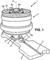
- the figure 1 represents an active vibration control device 1, intended to be mounted for example in a motor vehicle.
- the armature 3 may comprise a magnetically permeable portion 5b disposed in the moving assembly, and whose utility will be seen further.
- the moving element 4 comprises an electric coil 7 extending around the axis of displacement Z and mounted in a magnetically permeable carcass 8, slidably mounted on the second spacer 5b along the axis of displacement Z.
- the coil 7 and the carcass surround the armature 3.
- the moving element is connected to the armature 3 by at least one spring, for example first and second springs 9, 10 urging the moving element 4 towards a rest position.
- the springs 9, 10 may in particular be flat springs extending substantially radially with respect to the Z axis.
- a first annular spring 9 may be disposed around the central rod 6 with its inner periphery mounted tightly between the first spacer 5 and the magnetically permeable portion 5a.
- the outer periphery of the first spring 9 can be secured to the carcass 8, for example by means of a ring 8a screwed under the carcass 8 so that the outer periphery of the first spring 9 is clamped between the ring 8a and the carcass 8.
- a second annular spring 10 may be arranged around the central rod 6 with its inner periphery mounted tightly between the second spacer 5b and the enlarged head 6a of the central rod, possibly with the interposition of a washer 6b between the enlarged head 6a and the second spring 10.
- the outer periphery of the second spring 10 may be secured to the carcass 8, for example by means of a ring 8b screwed onto the carcass 8 so that the outer periphery of the second spring 10 is clamped between the ring 8b and the carcass 8.
- the coil 7, the casing 8 and the magnetically permeable part 5a of the armature are configured so that, when the coil is traversed by a variable current, it generates a magnetic field adapted to move the mobile assembly 4 along the axis of Z displacement thereby generating vibrations.
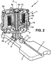
- the coil 7 is electrically powered by the vehicle, in a manner known per se, for example by a cable 11 having a connector 12 connected to a complementary connector 13 fixed to the support 2 ( figures 2 and 3 ).
- the connector 13 is connected to a power supply circuit 14 secured to the armature 3.
- This power supply circuit 14 may simply consist of a cable or electrically conductive tracks, or possibly comprise electronic components.
- the power supply circuit 14 is connected to the coil 7 by at least one conductive portion 18, 19 of at least one of the springs 9, 10, for example the first spring.
- the coil 7 can be connected to the at least one conductive part 18, 19 by conducting wires 16.
- said at least one conductive part 18, 19 can be connected to the power supply circuit 14 in the vicinity of the inner periphery of the spring 9, and the coil 7 can be connected to said at least one conductive part 18, 19 in the vicinity of the outer periphery of the spring 9.
- the spring 9 may comprise an elastic body 17 of electrically insulating material and at least one conductive circuit 18, 19 attached to the elastic body 17, for example in the form of a printed circuit.
- Said electrically insulating material may be a composite material comprising fibers embedded in a resin (glass, carbon, basalt or other fibers).
- the spring 9 comprises two separate circuits 18, 19 and isolated from each other.
- Each conductive circuit 18, 19 may comprise a conductive metal or alloy, or a conductive ink. It can be deposited on the surface of the elastic body 17 or on an intermediate layer.
- Each conductive circuit 18, 19 may extend between two ends forming contacts, a radially inner contact 20 adapted to connect to the supply circuit 14 by welding or single contact, and a radially outer contact 21 adapted to connect to the coil 7 by welding or single contact.
- the two conductive circuits 18, 19 may be on the same face of the spring 9.
- the contacts 20, 21 or one of them could be replaced by a connector.
- one or more electronic components could be welded to the conductive circuits 18, 19.
Landscapes
- Engineering & Computer Science (AREA)
- General Engineering & Computer Science (AREA)
- Physics & Mathematics (AREA)
- Mechanical Engineering (AREA)
- Electromagnetism (AREA)
- Power Engineering (AREA)
- Acoustics & Sound (AREA)
- Aviation & Aerospace Engineering (AREA)
- Apparatuses For Generation Of Mechanical Vibrations (AREA)
- Vibration Prevention Devices (AREA)
- Reciprocating, Oscillating Or Vibrating Motors (AREA)
Claims (6)
- Vorrichtung zur aktiven Schwingungsregulierung, umfassend:- ein Gestell (3), umfassend wenigstens einen magnetisch permeablen Abschnitt (5a),- ein bewegliches Teil (4), umfassend eine Spule (7), die sich um eine Verlagerungsachse (Z) erstreckt und einem magnetisch permeablen Gerüst (8) zugeordnet ist, das in Bezug auf das Gestell (3) entlang der Verlagerungsachse (Z) verschiebbar angebracht ist,- wenigstens eine Feder (9), welche das Gestell (3) mit dem beweglichen Teil (4) verbindet, wobei die Feder das bewegliche Teil (4) zu einer Ruheposition hin drängt,wobei die Spule (7) und das Gerüst (8) dazu konfiguriert sind, dass dann, wenn die Spule (7) von einem variablen Strom durchflossen wird, diese ein Magnetfeld erzeugt, das dazu angepasst ist, das bewegliche Teil (4) entlang der Verlagerungsachse (Z) zu verlagern und auf diese Weise Schwingungen zu erzeugen, wobei das Gestell (3) einen elektrischen Versorgungsschaltkreis (14) umfasst, dadurch gekennzeichnet, dass die Feder (9) einen elastischen Körper (17) aus einem elektrisch isolierenden Material umfasst und wenigstens einen auf den elastischen Körper (17) aufgebrachten Leiterschaltkreis (18, 19) umfasst, der den elektrischen Versorgungsschaltkreis (14) mit der Spule (7) verbindet.
- Vorrichtung zur aktiven Schwingungsregulierung nach Anspruch 1, wobei der Leiterschaltkreis (18, 19) ein aufgedruckter Schaltkreis ist.
- Vorrichtung zur aktiven Schwingungsregulierung nach Anspruch 1 oder Anspruch 2, wobei das elektrisch isolierende Material ein Verbundmaterial ist, welches in einem Harz/Kunstharz getränkte Fasern umfasst.
- Vorrichtung zur aktiven Schwingungsregulierung nach einem der vorhergehenden Ansprüche, wobei das Gestell (3) von dem Gerüst (8) umgeben ist, wobei die Feder (9) eine im Wesentlichen ringförmige Form aufweist, mit einem Innenumfang, der fest mit dem Gestell (3) verbunden ist, und mit einem Außenumfang, der fest mit dem Gerüst (8) verbunden ist, und wobei der Leiterschaltkreis (18, 19) sich zwischen einem ersten Ende (20), welches dem Innenumfang benachbart und mit dem elektrischen Versorgungsschaltkreis (14) verbunden ist, und einem zweiten Ende (21) erstreckt, welches dem Außenumfang benachbart und mit der Spule (7) verbunden ist.
- Vorrichtung zur aktiven Schwingungsregulierung nach einem der vorhergehenden Ansprüche, wobei die Feder (9) zwei unabhängige Leiterschaltkreise (18, 19) umfasst, welche den elektrischen Versorgungsschaltkreis (14) mit der Spule (7) verbinden.
- Vorrichtung zur aktiven Schwingungsregulierung nach einem der vorhergehenden Ansprüche, wobei die Feder (9) im Wesentlichen flach ist.
Applications Claiming Priority (1)
| Application Number | Priority Date | Filing Date | Title |
|---|---|---|---|
| FR1557129A FR3039694B1 (fr) | 2015-07-27 | 2015-07-27 | Dispositif de controle vibratoire actif |
Publications (2)
| Publication Number | Publication Date |
|---|---|
| EP3124822A1 EP3124822A1 (de) | 2017-02-01 |
| EP3124822B1 true EP3124822B1 (de) | 2018-02-14 |
Family
ID=54608710
Family Applications (1)
| Application Number | Title | Priority Date | Filing Date |
|---|---|---|---|
| EP16180959.5A Active EP3124822B1 (de) | 2015-07-27 | 2016-07-25 | Vorrichtung zur aktiven schwingungskontrolle |
Country Status (6)
| Country | Link |
|---|---|
| US (1) | US10181778B2 (de) |
| EP (1) | EP3124822B1 (de) |
| JP (1) | JP6745667B2 (de) |
| KR (1) | KR20170013188A (de) |
| CN (1) | CN106394158B (de) |
| FR (1) | FR3039694B1 (de) |
Families Citing this family (3)
| Publication number | Priority date | Publication date | Assignee | Title |
|---|---|---|---|---|
| JP6746372B2 (ja) * | 2016-05-13 | 2020-08-26 | 住友理工株式会社 | 電磁式アクチュエータおよび能動型制振装置と能動型防振装置 |
| GB2565121A (en) * | 2017-08-03 | 2019-02-06 | Bentley Motors Ltd | Method and apparatus for enhancing vehicle sound and/or vibrations |
| WO2023086308A1 (en) * | 2021-11-09 | 2023-05-19 | Fca Us Llc | Battery electric vehicle active sound and vibration enhancement systems |
Family Cites Families (17)
| Publication number | Priority date | Publication date | Assignee | Title |
|---|---|---|---|---|
| FR1557129A (de) | 1967-12-29 | 1969-02-14 | ||
| US4285054A (en) * | 1979-07-27 | 1981-08-18 | Mark Products, Inc. | Geophone |
| GB8908980D0 (en) | 1989-04-20 | 1989-06-07 | Lotus Group Plc | Treatment of noise in vehicles |
| JPH03207253A (ja) * | 1990-01-09 | 1991-09-10 | Fujitsu Ltd | 電源接続方法 |
| JPH1038020A (ja) * | 1996-07-26 | 1998-02-13 | Tokai Rubber Ind Ltd | 制振器 |
| FR2765647B1 (fr) * | 1997-07-07 | 2002-01-11 | Jacques Clausin | Reducteur de vibrations monoaxe accorde a bande large et de grande legerete |
| US6129527A (en) * | 1999-04-16 | 2000-10-10 | Litton Systems, Inc. | Electrically operated linear motor with integrated flexure spring and circuit for use in reciprocating compressor |
| FR2860564B1 (fr) | 2003-10-01 | 2007-07-13 | Hutchinson | Systeme d'amortissement de vibrations |
| FR2860658B1 (fr) | 2003-10-01 | 2006-01-13 | Hutchinson | Dispositif actif d'amortissement de vibrations d'un element vibrant |
| DE102005012463B3 (de) | 2005-03-18 | 2006-06-08 | Audi Ag | Verfahren zur Ergänzung eines Motorgeräusches eines Kraftfahrzeuges mit einem mittels eines Aktors erzeugten Zusatzgeräusch sowie eine Vorrichtung zur Durchführung des Verfahrens |
| JP2009273224A (ja) * | 2008-05-07 | 2009-11-19 | Aisin Seiki Co Ltd | リニアアクチュエータ |
| US8139367B2 (en) * | 2008-09-25 | 2012-03-20 | Motorola Mobility, Inc. | Torsion spring mechanism supportive of a flexible printed circuit |
| TWI384729B (zh) * | 2009-09-15 | 2013-02-01 | Largan Precision Co Ltd | 線性馬達 |
| TWI504085B (zh) * | 2010-04-09 | 2015-10-11 | Hon Hai Prec Ind Co Ltd | 彈片、音圈馬達及相機模組 |
| KR101184284B1 (ko) * | 2010-06-23 | 2012-09-26 | 주식회사 파브코 | 차량용 능동 동흡진기 장치 |
| FR2968053B1 (fr) * | 2010-11-26 | 2013-08-23 | Hutchinson | Dispositif de controle vibratoire actif, vehicule comportant un tel dispositif et chape active pour un tel dispositif. |
| KR101243615B1 (ko) * | 2011-06-20 | 2013-03-14 | 주식회사 파브코 | 능동댐퍼 |
-
2015
- 2015-07-27 FR FR1557129A patent/FR3039694B1/fr not_active Expired - Fee Related
-
2016
- 2016-07-25 EP EP16180959.5A patent/EP3124822B1/de active Active
- 2016-07-26 JP JP2016146164A patent/JP6745667B2/ja active Active
- 2016-07-26 US US15/219,567 patent/US10181778B2/en active Active
- 2016-07-27 CN CN201610597740.7A patent/CN106394158B/zh active Active
- 2016-07-27 KR KR1020160095607A patent/KR20170013188A/ko not_active Withdrawn
Non-Patent Citations (1)
| Title |
|---|
| None * |
Also Published As
| Publication number | Publication date |
|---|---|
| CN106394158B (zh) | 2021-05-07 |
| JP6745667B2 (ja) | 2020-08-26 |
| US10181778B2 (en) | 2019-01-15 |
| KR20170013188A (ko) | 2017-02-06 |
| CN106394158A (zh) | 2017-02-15 |
| US20170033675A1 (en) | 2017-02-02 |
| FR3039694B1 (fr) | 2018-06-15 |
| FR3039694A1 (fr) | 2017-02-03 |
| JP2017024004A (ja) | 2017-02-02 |
| EP3124822A1 (de) | 2017-02-01 |
Similar Documents
| Publication | Publication Date | Title |
|---|---|---|
| EP3221773B1 (de) | Haptische rückkopplungsvorrichtung für ein kraftfahrzeug | |
| FR2904060B1 (fr) | Demarreur ayant un element de connexion connectant electriquement un commutateur magnetique et un moteur electrique | |
| EP3124822B1 (de) | Vorrichtung zur aktiven schwingungskontrolle | |
| FR2930657A1 (fr) | Dispositif de commande a retour haptique et actionneur electromagnetique correspondant | |
| FR2797922A1 (fr) | Outil guide manuellement | |
| RU2373915C2 (ru) | Ультразвуковой генератор и устройство для ухода за кожей, содержащее указанный генератор | |
| EP1264387B1 (de) | Bürstenhalter mit lamellierten bürsten, feder und dämpfer | |
| FR2483138A1 (fr) | Systeme rotor pour machine electrique | |
| EP2458243B1 (de) | Aktive Schwingungsdämpfungsvorrichtung, Fahrzeug damit und Aktive Bedeckung für diese Vorrichtung | |
| FR2933248A1 (fr) | Installation de conversion de flexion generant de l'energie electrique a partir de deformations et module de circuit equipe d'une telle installation. | |
| FR2997566A1 (fr) | Dispositif de connexion pour la transmission de courant haute tension dans le domaine des vehicules automobiles | |
| FR2676589A1 (fr) | Commutateur electromagnetique. | |
| EP3637788B1 (de) | Elektrodynamischer lautsprecher, der eine elastische halterung zum stützen eines flexiblen leiters umfasst | |
| FR3015128A1 (fr) | Detecteur de proximite | |
| FR2535122A1 (fr) | Dispositif antitorsion pour cable electrique | |
| EP0681111A1 (de) | Dämpfungsvorrichtung für einen Bowdenzug | |
| FR2644848A3 (fr) | Dispositif electromagnetique pour la commande de l'alimentation en courant du moteur electrique de demarrage d'un moteur a combustion interne | |
| EP3578849B1 (de) | Aktive hydraulische schwingungsdämpfende vorrichtung und fahrzeug, das eine solche aktive hydraulische schwingungsdämpfende vorrichtung umfasst | |
| KR100448395B1 (ko) | 차량용 발전기의 브러시 홀딩장치 | |
| FR2805660A1 (fr) | Ensemble d'extremite pour contacteur de demarreur pour vehicule, notamment automobile, et contacteur comportant un tel ensemble d'extremite | |
| FR3128925A1 (fr) | Balai d'essuie-glace notamment pour un véhicule automobile | |
| FR2728400A3 (fr) | Convecteur anti-parasite de bougie d'allumage | |
| FR2885748A1 (fr) | Boitier de collecteur pour moteur electrique. | |
| FR3155975A1 (fr) | Connecteur électrique pour caméra de contrôle et caméra de contrôle associée | |
| EP3341594A1 (de) | Elektrischer verbinder eines elektromagnetischen aktuators für ein ventil |
Legal Events
| Date | Code | Title | Description |
|---|---|---|---|
| PUAI | Public reference made under article 153(3) epc to a published international application that has entered the european phase |
Free format text: ORIGINAL CODE: 0009012 |
|
| STAA | Information on the status of an ep patent application or granted ep patent |
Free format text: STATUS: REQUEST FOR EXAMINATION WAS MADE |
|
| 17P | Request for examination filed |
Effective date: 20160725 |
|
| AK | Designated contracting states |
Kind code of ref document: A1 Designated state(s): AL AT BE BG CH CY CZ DE DK EE ES FI FR GB GR HR HU IE IS IT LI LT LU LV MC MK MT NL NO PL PT RO RS SE SI SK SM TR |
|
| AX | Request for extension of the european patent |
Extension state: BA ME |
|
| RIC1 | Information provided on ipc code assigned before grant |
Ipc: F16F 7/10 20060101AFI20170821BHEP |
|
| GRAP | Despatch of communication of intention to grant a patent |
Free format text: ORIGINAL CODE: EPIDOSNIGR1 |
|
| STAA | Information on the status of an ep patent application or granted ep patent |
Free format text: STATUS: GRANT OF PATENT IS INTENDED |
|
| INTG | Intention to grant announced |
Effective date: 20171106 |
|
| GRAS | Grant fee paid |
Free format text: ORIGINAL CODE: EPIDOSNIGR3 |
|
| GRAA | (expected) grant |
Free format text: ORIGINAL CODE: 0009210 |
|
| STAA | Information on the status of an ep patent application or granted ep patent |
Free format text: STATUS: THE PATENT HAS BEEN GRANTED |
|
| AK | Designated contracting states |
Kind code of ref document: B1 Designated state(s): AL AT BE BG CH CY CZ DE DK EE ES FI FR GB GR HR HU IE IS IT LI LT LU LV MC MK MT NL NO PL PT RO RS SE SI SK SM TR |
|
| REG | Reference to a national code |
Ref country code: GB Ref legal event code: FG4D Free format text: NOT ENGLISH |
|
| REG | Reference to a national code |
Ref country code: CH Ref legal event code: EP |
|
| REG | Reference to a national code |
Ref country code: IE Ref legal event code: FG4D Free format text: LANGUAGE OF EP DOCUMENT: FRENCH |
|
| REG | Reference to a national code |
Ref country code: DE Ref legal event code: R096 Ref document number: 602016001637 Country of ref document: DE Ref country code: AT Ref legal event code: REF Ref document number: 970040 Country of ref document: AT Kind code of ref document: T Effective date: 20180315 |
|
| REG | Reference to a national code |
Ref country code: NL Ref legal event code: MP Effective date: 20180214 |
|
| REG | Reference to a national code |
Ref country code: AT Ref legal event code: MK05 Ref document number: 970040 Country of ref document: AT Kind code of ref document: T Effective date: 20180214 |
|
| REG | Reference to a national code |
Ref country code: FR Ref legal event code: PLFP Year of fee payment: 3 |
|
| PG25 | Lapsed in a contracting state [announced via postgrant information from national office to epo] |
Ref country code: ES Free format text: LAPSE BECAUSE OF FAILURE TO SUBMIT A TRANSLATION OF THE DESCRIPTION OR TO PAY THE FEE WITHIN THE PRESCRIBED TIME-LIMIT Effective date: 20180214 Ref country code: HR Free format text: LAPSE BECAUSE OF FAILURE TO SUBMIT A TRANSLATION OF THE DESCRIPTION OR TO PAY THE FEE WITHIN THE PRESCRIBED TIME-LIMIT Effective date: 20180214 Ref country code: NO Free format text: LAPSE BECAUSE OF FAILURE TO SUBMIT A TRANSLATION OF THE DESCRIPTION OR TO PAY THE FEE WITHIN THE PRESCRIBED TIME-LIMIT Effective date: 20180514 Ref country code: LT Free format text: LAPSE BECAUSE OF FAILURE TO SUBMIT A TRANSLATION OF THE DESCRIPTION OR TO PAY THE FEE WITHIN THE PRESCRIBED TIME-LIMIT Effective date: 20180214 Ref country code: FI Free format text: LAPSE BECAUSE OF FAILURE TO SUBMIT A TRANSLATION OF THE DESCRIPTION OR TO PAY THE FEE WITHIN THE PRESCRIBED TIME-LIMIT Effective date: 20180214 Ref country code: NL Free format text: LAPSE BECAUSE OF FAILURE TO SUBMIT A TRANSLATION OF THE DESCRIPTION OR TO PAY THE FEE WITHIN THE PRESCRIBED TIME-LIMIT Effective date: 20180214 Ref country code: CY Free format text: LAPSE BECAUSE OF FAILURE TO SUBMIT A TRANSLATION OF THE DESCRIPTION OR TO PAY THE FEE WITHIN THE PRESCRIBED TIME-LIMIT Effective date: 20180214 |
|
| PG25 | Lapsed in a contracting state [announced via postgrant information from national office to epo] |
Ref country code: SE Free format text: LAPSE BECAUSE OF FAILURE TO SUBMIT A TRANSLATION OF THE DESCRIPTION OR TO PAY THE FEE WITHIN THE PRESCRIBED TIME-LIMIT Effective date: 20180214 Ref country code: LV Free format text: LAPSE BECAUSE OF FAILURE TO SUBMIT A TRANSLATION OF THE DESCRIPTION OR TO PAY THE FEE WITHIN THE PRESCRIBED TIME-LIMIT Effective date: 20180214 Ref country code: GR Free format text: LAPSE BECAUSE OF FAILURE TO SUBMIT A TRANSLATION OF THE DESCRIPTION OR TO PAY THE FEE WITHIN THE PRESCRIBED TIME-LIMIT Effective date: 20180515 Ref country code: RS Free format text: LAPSE BECAUSE OF FAILURE TO SUBMIT A TRANSLATION OF THE DESCRIPTION OR TO PAY THE FEE WITHIN THE PRESCRIBED TIME-LIMIT Effective date: 20180214 Ref country code: BG Free format text: LAPSE BECAUSE OF FAILURE TO SUBMIT A TRANSLATION OF THE DESCRIPTION OR TO PAY THE FEE WITHIN THE PRESCRIBED TIME-LIMIT Effective date: 20180514 Ref country code: AT Free format text: LAPSE BECAUSE OF FAILURE TO SUBMIT A TRANSLATION OF THE DESCRIPTION OR TO PAY THE FEE WITHIN THE PRESCRIBED TIME-LIMIT Effective date: 20180214 |
|
| PG25 | Lapsed in a contracting state [announced via postgrant information from national office to epo] |
Ref country code: MT Free format text: LAPSE BECAUSE OF FAILURE TO SUBMIT A TRANSLATION OF THE DESCRIPTION OR TO PAY THE FEE WITHIN THE PRESCRIBED TIME-LIMIT Effective date: 20180214 |
|
| PG25 | Lapsed in a contracting state [announced via postgrant information from national office to epo] |
Ref country code: RO Free format text: LAPSE BECAUSE OF FAILURE TO SUBMIT A TRANSLATION OF THE DESCRIPTION OR TO PAY THE FEE WITHIN THE PRESCRIBED TIME-LIMIT Effective date: 20180214 Ref country code: IT Free format text: LAPSE BECAUSE OF FAILURE TO SUBMIT A TRANSLATION OF THE DESCRIPTION OR TO PAY THE FEE WITHIN THE PRESCRIBED TIME-LIMIT Effective date: 20180214 Ref country code: AL Free format text: LAPSE BECAUSE OF FAILURE TO SUBMIT A TRANSLATION OF THE DESCRIPTION OR TO PAY THE FEE WITHIN THE PRESCRIBED TIME-LIMIT Effective date: 20180214 Ref country code: PL Free format text: LAPSE BECAUSE OF FAILURE TO SUBMIT A TRANSLATION OF THE DESCRIPTION OR TO PAY THE FEE WITHIN THE PRESCRIBED TIME-LIMIT Effective date: 20180214 Ref country code: EE Free format text: LAPSE BECAUSE OF FAILURE TO SUBMIT A TRANSLATION OF THE DESCRIPTION OR TO PAY THE FEE WITHIN THE PRESCRIBED TIME-LIMIT Effective date: 20180214 |
|
| REG | Reference to a national code |
Ref country code: DE Ref legal event code: R097 Ref document number: 602016001637 Country of ref document: DE |
|
| PG25 | Lapsed in a contracting state [announced via postgrant information from national office to epo] |
Ref country code: DK Free format text: LAPSE BECAUSE OF FAILURE TO SUBMIT A TRANSLATION OF THE DESCRIPTION OR TO PAY THE FEE WITHIN THE PRESCRIBED TIME-LIMIT Effective date: 20180214 Ref country code: CZ Free format text: LAPSE BECAUSE OF FAILURE TO SUBMIT A TRANSLATION OF THE DESCRIPTION OR TO PAY THE FEE WITHIN THE PRESCRIBED TIME-LIMIT Effective date: 20180214 Ref country code: SK Free format text: LAPSE BECAUSE OF FAILURE TO SUBMIT A TRANSLATION OF THE DESCRIPTION OR TO PAY THE FEE WITHIN THE PRESCRIBED TIME-LIMIT Effective date: 20180214 Ref country code: SM Free format text: LAPSE BECAUSE OF FAILURE TO SUBMIT A TRANSLATION OF THE DESCRIPTION OR TO PAY THE FEE WITHIN THE PRESCRIBED TIME-LIMIT Effective date: 20180214 |
|
| PLBE | No opposition filed within time limit |
Free format text: ORIGINAL CODE: 0009261 |
|
| STAA | Information on the status of an ep patent application or granted ep patent |
Free format text: STATUS: NO OPPOSITION FILED WITHIN TIME LIMIT |
|
| 26N | No opposition filed |
Effective date: 20181115 |
|
| PG25 | Lapsed in a contracting state [announced via postgrant information from national office to epo] |
Ref country code: SI Free format text: LAPSE BECAUSE OF FAILURE TO SUBMIT A TRANSLATION OF THE DESCRIPTION OR TO PAY THE FEE WITHIN THE PRESCRIBED TIME-LIMIT Effective date: 20180214 |
|
| PG25 | Lapsed in a contracting state [announced via postgrant information from national office to epo] |
Ref country code: MC Free format text: LAPSE BECAUSE OF FAILURE TO SUBMIT A TRANSLATION OF THE DESCRIPTION OR TO PAY THE FEE WITHIN THE PRESCRIBED TIME-LIMIT Effective date: 20180214 Ref country code: LU Free format text: LAPSE BECAUSE OF NON-PAYMENT OF DUE FEES Effective date: 20180725 |
|
| REG | Reference to a national code |
Ref country code: BE Ref legal event code: MM Effective date: 20180731 |
|
| REG | Reference to a national code |
Ref country code: IE Ref legal event code: MM4A |
|
| PG25 | Lapsed in a contracting state [announced via postgrant information from national office to epo] |
Ref country code: IE Free format text: LAPSE BECAUSE OF NON-PAYMENT OF DUE FEES Effective date: 20180725 |
|
| PG25 | Lapsed in a contracting state [announced via postgrant information from national office to epo] |
Ref country code: BE Free format text: LAPSE BECAUSE OF NON-PAYMENT OF DUE FEES Effective date: 20180731 |
|
| REG | Reference to a national code |
Ref country code: CH Ref legal event code: PL |
|
| PG25 | Lapsed in a contracting state [announced via postgrant information from national office to epo] |
Ref country code: TR Free format text: LAPSE BECAUSE OF FAILURE TO SUBMIT A TRANSLATION OF THE DESCRIPTION OR TO PAY THE FEE WITHIN THE PRESCRIBED TIME-LIMIT Effective date: 20180214 |
|
| PG25 | Lapsed in a contracting state [announced via postgrant information from national office to epo] |
Ref country code: PT Free format text: LAPSE BECAUSE OF FAILURE TO SUBMIT A TRANSLATION OF THE DESCRIPTION OR TO PAY THE FEE WITHIN THE PRESCRIBED TIME-LIMIT Effective date: 20180214 Ref country code: CH Free format text: LAPSE BECAUSE OF NON-PAYMENT OF DUE FEES Effective date: 20190731 Ref country code: LI Free format text: LAPSE BECAUSE OF NON-PAYMENT OF DUE FEES Effective date: 20190731 |
|
| PG25 | Lapsed in a contracting state [announced via postgrant information from national office to epo] |
Ref country code: MK Free format text: LAPSE BECAUSE OF NON-PAYMENT OF DUE FEES Effective date: 20180214 Ref country code: HU Free format text: LAPSE BECAUSE OF FAILURE TO SUBMIT A TRANSLATION OF THE DESCRIPTION OR TO PAY THE FEE WITHIN THE PRESCRIBED TIME-LIMIT; INVALID AB INITIO Effective date: 20160725 |
|
| PG25 | Lapsed in a contracting state [announced via postgrant information from national office to epo] |
Ref country code: IS Free format text: LAPSE BECAUSE OF FAILURE TO SUBMIT A TRANSLATION OF THE DESCRIPTION OR TO PAY THE FEE WITHIN THE PRESCRIBED TIME-LIMIT Effective date: 20180614 |
|
| GBPC | Gb: european patent ceased through non-payment of renewal fee |
Effective date: 20200725 |
|
| PG25 | Lapsed in a contracting state [announced via postgrant information from national office to epo] |
Ref country code: GB Free format text: LAPSE BECAUSE OF NON-PAYMENT OF DUE FEES Effective date: 20200725 |
|
| P01 | Opt-out of the competence of the unified patent court (upc) registered |
Effective date: 20230526 |
|
| PGFP | Annual fee paid to national office [announced via postgrant information from national office to epo] |
Ref country code: DE Payment date: 20250722 Year of fee payment: 10 |
|
| PGFP | Annual fee paid to national office [announced via postgrant information from national office to epo] |
Ref country code: FR Payment date: 20250725 Year of fee payment: 10 |