EP3124822B1 - Active vibration control device - Google Patents
Active vibration control device Download PDFInfo
- Publication number
- EP3124822B1 EP3124822B1 EP16180959.5A EP16180959A EP3124822B1 EP 3124822 B1 EP3124822 B1 EP 3124822B1 EP 16180959 A EP16180959 A EP 16180959A EP 3124822 B1 EP3124822 B1 EP 3124822B1
- Authority
- EP
- European Patent Office
- Prior art keywords
- armature
- coil
- spring
- control device
- carcass
- Prior art date
- Legal status (The legal status is an assumption and is not a legal conclusion. Google has not performed a legal analysis and makes no representation as to the accuracy of the status listed.)
- Active
Links
- 239000012777 electrically insulating material Substances 0.000 claims description 6
- 239000002131 composite material Substances 0.000 claims description 4
- 239000011347 resin Substances 0.000 claims description 3
- 229920005989 resin Polymers 0.000 claims description 3
- 238000006073 displacement reaction Methods 0.000 description 8
- 125000006850 spacer group Chemical group 0.000 description 7
- 239000000835 fiber Substances 0.000 description 3
- 230000000284 resting effect Effects 0.000 description 2
- 238000003466 welding Methods 0.000 description 2
- OKTJSMMVPCPJKN-UHFFFAOYSA-N Carbon Chemical compound [C] OKTJSMMVPCPJKN-UHFFFAOYSA-N 0.000 description 1
- 239000000956 alloy Substances 0.000 description 1
- 229910045601 alloy Inorganic materials 0.000 description 1
- 229910052799 carbon Inorganic materials 0.000 description 1
- 230000000295 complement effect Effects 0.000 description 1
- 239000011521 glass Substances 0.000 description 1
- 230000010354 integration Effects 0.000 description 1
- 239000002184 metal Substances 0.000 description 1
- 210000000056 organ Anatomy 0.000 description 1
- 230000000717 retained effect Effects 0.000 description 1
Images

Classifications
-
- H—ELECTRICITY
- H02—GENERATION; CONVERSION OR DISTRIBUTION OF ELECTRIC POWER
- H02K—DYNAMO-ELECTRIC MACHINES
- H02K33/00—Motors with reciprocating, oscillating or vibrating magnet, armature or coil system
- H02K33/18—Motors with reciprocating, oscillating or vibrating magnet, armature or coil system with coil systems moving upon intermittent or reversed energisation thereof by interaction with a fixed field system, e.g. permanent magnets
-
- B—PERFORMING OPERATIONS; TRANSPORTING
- B60—VEHICLES IN GENERAL
- B60G—VEHICLE SUSPENSION ARRANGEMENTS
- B60G17/00—Resilient suspensions having means for adjusting the spring or vibration-damper characteristics, for regulating the distance between a supporting surface and a sprung part of vehicle or for locking suspension during use to meet varying vehicular or surface conditions, e.g. due to speed or load
- B60G17/02—Spring characteristics, e.g. mechanical springs and mechanical adjusting means
-
- F—MECHANICAL ENGINEERING; LIGHTING; HEATING; WEAPONS; BLASTING
- F16—ENGINEERING ELEMENTS AND UNITS; GENERAL MEASURES FOR PRODUCING AND MAINTAINING EFFECTIVE FUNCTIONING OF MACHINES OR INSTALLATIONS; THERMAL INSULATION IN GENERAL
- F16F—SPRINGS; SHOCK-ABSORBERS; MEANS FOR DAMPING VIBRATION
- F16F7/00—Vibration-dampers; Shock-absorbers
- F16F7/10—Vibration-dampers; Shock-absorbers using inertia effect
- F16F7/1005—Vibration-dampers; Shock-absorbers using inertia effect characterised by active control of the mass
- F16F7/1011—Vibration-dampers; Shock-absorbers using inertia effect characterised by active control of the mass by electromagnetic means
-
- F—MECHANICAL ENGINEERING; LIGHTING; HEATING; WEAPONS; BLASTING
- F16—ENGINEERING ELEMENTS AND UNITS; GENERAL MEASURES FOR PRODUCING AND MAINTAINING EFFECTIVE FUNCTIONING OF MACHINES OR INSTALLATIONS; THERMAL INSULATION IN GENERAL
- F16F—SPRINGS; SHOCK-ABSORBERS; MEANS FOR DAMPING VIBRATION
- F16F15/00—Suppression of vibrations in systems; Means or arrangements for avoiding or reducing out-of-balance forces, e.g. due to motion
- F16F15/02—Suppression of vibrations of non-rotating, e.g. reciprocating systems; Suppression of vibrations of rotating systems by use of members not moving with the rotating systems
- F16F15/03—Suppression of vibrations of non-rotating, e.g. reciprocating systems; Suppression of vibrations of rotating systems by use of members not moving with the rotating systems using magnetic or electromagnetic means
-
- F—MECHANICAL ENGINEERING; LIGHTING; HEATING; WEAPONS; BLASTING
- F16—ENGINEERING ELEMENTS AND UNITS; GENERAL MEASURES FOR PRODUCING AND MAINTAINING EFFECTIVE FUNCTIONING OF MACHINES OR INSTALLATIONS; THERMAL INSULATION IN GENERAL
- F16F—SPRINGS; SHOCK-ABSORBERS; MEANS FOR DAMPING VIBRATION
- F16F15/00—Suppression of vibrations in systems; Means or arrangements for avoiding or reducing out-of-balance forces, e.g. due to motion
- F16F15/02—Suppression of vibrations of non-rotating, e.g. reciprocating systems; Suppression of vibrations of rotating systems by use of members not moving with the rotating systems
- F16F15/04—Suppression of vibrations of non-rotating, e.g. reciprocating systems; Suppression of vibrations of rotating systems by use of members not moving with the rotating systems using elastic means
-
- H—ELECTRICITY
- H02—GENERATION; CONVERSION OR DISTRIBUTION OF ELECTRIC POWER
- H02K—DYNAMO-ELECTRIC MACHINES
- H02K3/00—Details of windings
- H02K3/46—Fastening of windings on the stator or rotor structure
- H02K3/50—Fastening of winding heads, equalising connectors, or connections thereto
-
- B—PERFORMING OPERATIONS; TRANSPORTING
- B60—VEHICLES IN GENERAL
- B60G—VEHICLE SUSPENSION ARRANGEMENTS
- B60G2202/00—Indexing codes relating to the type of spring, damper or actuator
- B60G2202/10—Type of spring
- B60G2202/16—Magnetic spring
-
- B—PERFORMING OPERATIONS; TRANSPORTING
- B60—VEHICLES IN GENERAL
- B60G—VEHICLE SUSPENSION ARRANGEMENTS
- B60G2600/00—Indexing codes relating to particular elements, systems or processes used on suspension systems or suspension control systems
- B60G2600/18—Automatic control means
- B60G2600/182—Active control means
Definitions
- the present invention relates to active vibration control devices, particularly for vehicles.
- Devices of this type are particularly advantageous because the mass of the coil and the carcass is put to good use for the generation of vibrations, since the moving equipment needs to be relatively heavy for this purpose.
- the total mass of the active vibratory control device is less than when the coil and the carcass are fixed and the moving armature.
- the document FR1557129 also describes an antivibration device of the aforementioned type, wherein the armature comprises a power supply circuit. This antivibration device is however complex.
- the document FR2765647 considered most relevant, describes the preamble of claim 1.
- the present invention is intended to overcome these disadvantages.
- an active vibratory control device of the kind in question is characterized in that the spring comprises an elastic body of electrically insulating material and at least one conductive circuit attached to the elastic body, connecting said circuit power supply to the coil.
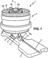
- the figure 1 represents an active vibration control device 1, intended to be mounted for example in a motor vehicle.
- the armature 3 may comprise a magnetically permeable portion 5b disposed in the moving assembly, and whose utility will be seen further.
- the moving element 4 comprises an electric coil 7 extending around the axis of displacement Z and mounted in a magnetically permeable carcass 8, slidably mounted on the second spacer 5b along the axis of displacement Z.
- the coil 7 and the carcass surround the armature 3.
- the moving element is connected to the armature 3 by at least one spring, for example first and second springs 9, 10 urging the moving element 4 towards a rest position.
- the springs 9, 10 may in particular be flat springs extending substantially radially with respect to the Z axis.
- a first annular spring 9 may be disposed around the central rod 6 with its inner periphery mounted tightly between the first spacer 5 and the magnetically permeable portion 5a.
- the outer periphery of the first spring 9 can be secured to the carcass 8, for example by means of a ring 8a screwed under the carcass 8 so that the outer periphery of the first spring 9 is clamped between the ring 8a and the carcass 8.
- a second annular spring 10 may be arranged around the central rod 6 with its inner periphery mounted tightly between the second spacer 5b and the enlarged head 6a of the central rod, possibly with the interposition of a washer 6b between the enlarged head 6a and the second spring 10.
- the outer periphery of the second spring 10 may be secured to the carcass 8, for example by means of a ring 8b screwed onto the carcass 8 so that the outer periphery of the second spring 10 is clamped between the ring 8b and the carcass 8.
- the coil 7, the casing 8 and the magnetically permeable part 5a of the armature are configured so that, when the coil is traversed by a variable current, it generates a magnetic field adapted to move the mobile assembly 4 along the axis of Z displacement thereby generating vibrations.
- the coil 7 is electrically powered by the vehicle, in a manner known per se, for example by a cable 11 having a connector 12 connected to a complementary connector 13 fixed to the support 2 ( figures 2 and 3 ).
- the connector 13 is connected to a power supply circuit 14 secured to the armature 3.
- This power supply circuit 14 may simply consist of a cable or electrically conductive tracks, or possibly comprise electronic components.
- the power supply circuit 14 is connected to the coil 7 by at least one conductive portion 18, 19 of at least one of the springs 9, 10, for example the first spring.
- the coil 7 can be connected to the at least one conductive part 18, 19 by conducting wires 16.
- said at least one conductive part 18, 19 can be connected to the power supply circuit 14 in the vicinity of the inner periphery of the spring 9, and the coil 7 can be connected to said at least one conductive part 18, 19 in the vicinity of the outer periphery of the spring 9.
- the spring 9 may comprise an elastic body 17 of electrically insulating material and at least one conductive circuit 18, 19 attached to the elastic body 17, for example in the form of a printed circuit.
- Said electrically insulating material may be a composite material comprising fibers embedded in a resin (glass, carbon, basalt or other fibers).
- the spring 9 comprises two separate circuits 18, 19 and isolated from each other.
- Each conductive circuit 18, 19 may comprise a conductive metal or alloy, or a conductive ink. It can be deposited on the surface of the elastic body 17 or on an intermediate layer.
- Each conductive circuit 18, 19 may extend between two ends forming contacts, a radially inner contact 20 adapted to connect to the supply circuit 14 by welding or single contact, and a radially outer contact 21 adapted to connect to the coil 7 by welding or single contact.
- the two conductive circuits 18, 19 may be on the same face of the spring 9.
- the contacts 20, 21 or one of them could be replaced by a connector.
- one or more electronic components could be welded to the conductive circuits 18, 19.
Landscapes
- Engineering & Computer Science (AREA)
- General Engineering & Computer Science (AREA)
- Physics & Mathematics (AREA)
- Mechanical Engineering (AREA)
- Electromagnetism (AREA)
- Power Engineering (AREA)
- Acoustics & Sound (AREA)
- Aviation & Aerospace Engineering (AREA)
- Apparatuses For Generation Of Mechanical Vibrations (AREA)
- Vibration Prevention Devices (AREA)
- Reciprocating, Oscillating Or Vibrating Motors (AREA)
Description
La présente invention est relative aux dispositifs de contrôle vibratoire actifs, notamment pour véhicules.The present invention relates to active vibration control devices, particularly for vehicles.
Plus particulièrement, l'invention concerne un dispositif de contrôle vibratoire actif, comprenant :
- une armature comprenant au moins une partie magnétiquement perméable,
- un équipage mobile comportant une bobine s'étendant autour d'un axe de déplacement et associée à une carcasse magnétiquement perméable, montée coulissante par rapport à l'armature selon l'axe de déplacement,
- au moins un ressort reliant l'armature à l'équipage mobile, ledit ressort sollicitant l'équipage mobile vers une position de repos,
- an armature comprising at least one magnetically permeable part,
- a moving element comprising a coil extending around an axis of displacement and associated with a magnetically permeable carcass, slidably mounted relative to the armature along the axis of displacement,
- at least one spring connecting the armature to the moving element, said spring urging the moving element towards a rest position,
Un exemple de dispositif de ce type est décrit par exemple dans le document
Les dispositifs de ce type, sont particulièrement avantageux, parce que la masse de la bobine et de la carcasse est mise à profit pour la génération de vibrations, puisque l'équipage mobile a besoin d'être relativement lourd à cet effet. En particulier, la masse totale du dispositif de contrôle vibratoire actif est moindre que lorsque la bobine et la carcasse sont fixes et l'armature mobile.Devices of this type are particularly advantageous because the mass of the coil and the carcass is put to good use for the generation of vibrations, since the moving equipment needs to be relatively heavy for this purpose. In particular, the total mass of the active vibratory control device is less than when the coil and the carcass are fixed and the moving armature.
Ces dispositifs de contrôle vibratoire actif connus présentent toutefois l'inconvénient que le câble d'alimentation électrique de la bobine, est mobile avec la bobine selon l'axe de déplacement. Pour garantir la durée de vie du système et donc assurer la tenue en fatigue du câble et de ses connexions, celui-ci est généralement disposé en forme de boucle. Afin de minimiser les contraintes dans le câble lorsque la bobine est en mouvement, cette boucle doit être réalisée avec un câble souple et léger mais surtout être suffisamment longue et de grand rayon de courbure. Le dispositif est de fait encombrant, ce qui rend difficile l'implantation du dispositif sur véhicule et empêche l'intégration du dispositif dans un boîtier fixe.These known active vibratory control devices however have the disadvantage that the power supply cable of the coil is movable with the coil along the axis of displacement. To guarantee the duration of life of the system and thus ensure fatigue resistance of the cable and its connections, it is generally arranged in the form of a loop. In order to minimize the stresses in the cable when the coil is in motion, this loop must be made with a flexible and light cable but above all be sufficiently long and of great radius of curvature. The device is in fact bulky, which makes it difficult to implement the device on the vehicle and prevents the integration of the device in a fixed housing.
Le document
La présente invention a notamment pour but de pallier ces inconvénients.The present invention is intended to overcome these disadvantages.
A cet effet, selon l'invention, un dispositif de contrôle vibratoire actif du genre en question, est caractérisé en ce que le ressort comporte un corps élastique en matériau électriquement isolant et au moins un circuit conducteur rapporté sur le corps élastique, reliant ledit circuit d'alimentation électrique à la bobine.For this purpose, according to the invention, an active vibratory control device of the kind in question, is characterized in that the spring comprises an elastic body of electrically insulating material and at least one conductive circuit attached to the elastic body, connecting said circuit power supply to the coil.
Grâce à ces dispositions, on évite l'utilisation d'un câble souple pour alimenter la bobine, et on peut ainsi réduire l'encombrement du dispositif de contrôle vibratoire actif.With these provisions, it avoids the use of a flexible cable to power the coil, and can reduce the size of the active vibration control device.
On notera que les vibrations générées par le générateur de vibrations peuvent être notamment conçues:
- pour atténuer les vibrations venant d'un organe vibrant, comme enseigné par exemple dans le document
FR2860564 - et/ou pour créer des sons supplémentaires entendus à l'intérieur de l'habitacle et/ou à l'extérieur, par exemple pour créer artificiellement une sonorité d'un moteur autre que celui du véhicule, comme enseigné par exemple par le document
EP0469023 WO2006/097188
- to mitigate vibrations from a vibrating organ, as taught for example in the document
FR2860564 - and / or to create additional sounds heard inside the cockpit and / or outside, for example to artificially create a sound of an engine other than that of the vehicle, as taught for example by the document
EP0469023 WO2006 / 097188
Dans divers modes de réalisation du dispositif de contrôle vibratoire selon l'invention, on peut éventuellement avoir recours en outre à l'une et/ou à l'autre des dispositions suivantes :
- ledit circuit conducteur rapporté est un circuit imprimé ;
- ledit matériau électriquement isolant est un matériau composite comportant des fibres noyées dans une résine ;
- l'armature est entourée par la carcasse, le ressort présente une forme sensiblement annulaire ayant une périphérie intérieure solidarisée à l'armature et une périphérie extérieure solidarisée à la carcasse, et ledit circuit conducteur s'étend entre une première extrémité voisine de la périphérie intérieure et reliée au circuit d'alimentation électrique, et une deuxième extrémité voisine de la périphérie extérieure et reliée à la bobine ;
- le ressort comporte deux circuits conducteurs indépendants, reliant le circuit d'alimentation électrique à la bobine ;
- le ressort est sensiblement plat.
- said attached conductive circuit is a printed circuit;
- said electrically insulating material is a composite material comprising fibers embedded in a resin;
- the armature is surrounded by the carcass, the spring has a substantially annular shape having an inner periphery secured to the armature and an outer periphery secured to the carcass, and said conductive circuit extends between a first end adjacent to the inner periphery and connected to the power supply circuit, and a second end close to the outer periphery and connected to the coil;
- the spring comprises two independent conductive circuits, connecting the power supply circuit to the coil;
- the spring is substantially flat.
D'autres caractéristiques et avantages de l'invention apparaîtront au cours de la description suivante d'une de ses formes de réalisation, donnée à titre d'exemple non limitatif, en regard des dessins joints.Other features and advantages of the invention will become apparent from the following description of one of its embodiments, given by way of non-limiting example, with reference to the accompanying drawings.
Sur les dessins :
- la
figure 1 est une vue schématique en perspective illustrant un exemple de dispositif de contrôle vibratoire selon une forme de réalisation de l'invention, - la
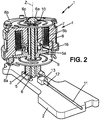
figure 2 est une vue en perspective et en coupe verticale du dispositif du dispositif de contrôle vibratoire de lafigure 1 , - et la
figure 3 est une vue en plan d'un des ressorts du dispositif de lafigure 2 .
- the
figure 1 is a schematic perspective view illustrating an example of a vibratory control device according to one embodiment of the invention, - the
figure 2 is a perspective view in vertical section of the device of the control device vibratory of thefigure 1 , - and the
figure 3 is a plan view of one of the springs of the device of thefigure 2 .
Sur les différentes figures, les mêmes références désignent des éléments identiques ou similaires.In the different figures, the same references designate identical or similar elements.
La
Le dispositif de contrôle vibratoire actif 1 peut être monté sur un support 2, par exemple solidaire de la caisse du véhicule, et peut comporter :
- une
armature 3 solidaire dusupport 2, - un équipage mobile 4 montée coulissant par rapport à l'armature 3 selon un axe de déplacement Z pouvant être par exemple sensiblement vertical.
- an
armature 3 secured to thesupport 2, - a
movable assembly 4 slidably mounted relative to thearmature 3 along an axis of displacement Z which may for example be substantially vertical.
Comme représenté sur la
Plus spécifiquement, l'armature 3 peut comporter par exemple :
- une tige centrale 6 rigide s'étendant selon l'axe Z et solidarisée au
support 2, - une
première entretoise 5 rigide entourant la tige centrale 6 et reposant sur lesupport 2, - la partie magnétiquement perméable 5a susmentionnée, entourant la tige centrale 6 au-dessus de l'entretoise 5,
- une deuxième entretoise rigide 5b entourant la tige centrale 6 et reposant sur la partie magnétiquement perméable 5a, Cette
deuxième entretoise 5b étant retenue sur la tige centrale par une tête élargir 6a formée à l'extrémité libre de latête 6.
- a rigid
central rod 6 extending along the axis Z and secured to thesupport 2, - a first
rigid spacer 5 surrounding thecentral rod 6 and resting on thesupport 2, - the magnetically
permeable part 5a mentioned above, surrounding thecentral rod 6 above thespacer 5, - a second
rigid spacer 5b surrounding thecentral rod 6 and resting on the magneticallypermeable portion 5a, Thissecond spacer 5b being retained on the central rod by a wideninghead 6a formed at the free end of thehead 6.
L'équipage mobile 4 comporte une bobine électrique 7 s'étendant autour de l'axe de déplacement Z et montée dans une carcasse magnétiquement perméable 8, montée coulissante sur la deuxième entretoise 5b selon l'axe de déplacement Z. La bobine 7 et la carcasse entourent l'armature 3.The moving
De plus, l'équipage mobile est relié à l'armature 3 par au moins un ressort, par exemple des premiers et deuxième ressorts 9, 10 sollicitant l'équipage mobile 4 vers une position de repos. Les ressorts 9, 10 peuvent notamment être des ressorts plats d'étendant sensiblement radialement par rapport à l'axe Z.In addition, the moving element is connected to the
Plus spécifiquement, un premier ressort 9 annulaire peut être disposé autour de la tige centrale 6 avec sa périphérie intérieure montée serrée entre la première entretoise 5 et la partie magnétiquement perméable 5a.More specifically, a first
La périphérie extérieure du premier ressort 9 peut être solidarisée à la carcasse 8, par exemple à l'aide d'une bague 8a vissée sous la carcasse 8 de façon que la périphérie extérieure du premier ressort 9 soit serrée entre la bague 8a et la carcasse 8.The outer periphery of the
Un deuxième ressort 10 annulaire peut être disposé autour de la tige centrale 6 avec sa périphérie intérieure montée serrée entre la deuxième entretoise 5b et la tête élargie 6a de la tige centrale, avec éventuellement interposition d'une rondelle 6b entre la tête élargie 6a et le deuxième ressort 10.A second
La périphérie extérieure du deuxième ressort 10 peut être solidarisée à la carcasse 8, par exemple à l'aide d'une bague 8b vissée sur la carcasse 8 de façon que la périphérie extérieure du deuxième ressort 10 soit serrée entre la bague 8b et la carcasse 8.The outer periphery of the
La bobine 7, la carcasse 8 et la partie magnétiquement perméable 5a de l'armature sont configurées pour que, lorsque la bobine est parcourue par un courant variable, elle génère un champ magnétique adapté pour déplacer l'équipage mobile 4 selon l'axe de déplacement Z en générant ainsi des vibrations.The
La bobine 7 est alimentée électriquement par le véhicule, de façon connue en soi, par exemple par un câble 11 ayant un connecteur 12 raccordé sur un connecteur complémentaire 13 fixé au support 2 (
Le circuit d'alimentation électrique 14 est relié à la bobine 7 par au moins une partie conductrice 18, 19 d'au moins un des ressorts 9, 10, par exemple le premier ressort.The
Eventuellement, la bobine 7 peut être reliée à ladite au moins une partie conductrice 18, 19 par des fils conducteurs 16.Optionally, the
Eventuellement, ladite au moins une partie conductrice 18, 19 peut être reliée au circuit d'alimentation électrique 14 au voisinage de la périphérie intérieure du ressort 9, et la bobine 7 peut être reliée ladite au moins une partie conductrice 18, 19 au voisinage de la périphérie extérieure du ressort 9.Optionally, said at least one
Comme représenté sur la
De préférence, le ressort 9 comporte deux circuits conducteurs 18, 19 distincts et isolés l'un de l'autre.Preferably, the
Chaque circuit conducteur 18, 19 peut comporter un métal ou alliage conducteur, ou une encre conductrice. Il peut être déposé à la surface du corps élastique 17 ou sur une couche intermédiaire.Each
Chaque circuit conducteur 18, 19 peut s'étendre entre deux extrémités formant des contacts, un contact radialement intérieur 20 adapté pour se connecter au circuit d'alimentation 14 par soudure ou simple contact, et un contact radialement extérieur 21 adapté pour se connecter à la bobine 7 par soudure ou simple contact.Les deux circuits conducteurs 18, 19 peuvent être sur une même face du ressort 9.Each
Eventuellement, les contacts 20, 21 ou l'un d'entre eux pourrait être remplacé par un connecteur.Optionally, the
Eventuellement, un ou des composants électroniques pourraient être soudés sur les circuits conducteurs 18, 19.Optionally, one or more electronic components could be welded to the
Claims (6)
- Active vibratory control device, comprising:- an armature (3) comprising at least one magnetically permeable part (5a),- a movable element (4) comprising a coil (7) extending around a movement axis (Z) and associated with a magnetically permeable carcass (8) mounted so as to slide with respect to the armature (3) along the movement axis (Z),- at least one spring (9) connecting the armature (3) to the movable element (4), said spring urging the movable element (4) towards an idle position,the coil (7) and the carcass (8) being configured so that, when the coil (7) has a variable current passing through it, it generates a magnetic field suitable for moving the movable element (4) along the movement axis (Z), thus generating vibrations,
the armature (3) comprising an electrical supply circuit (14),
characterised in that the spring (9) comprises an elastic body (17) made from electrically insulating material and at least one conductive circuit (18, 19) attached to the elastic body (17), connecting said electrical supply circuit (14) to the coil (7). - Active vibratory control device according to claim 1, in which said conductive circuit (18, 19) is a printed circuit.
- Active vibratory control device according to claim 1 or claim 2, in which said electrically insulating material is a composite material comprising fibres embedded in a resin.
- Active vibratory control device according to any one of the preceding claims, in which the armature (3) is surrounded by the carcass (8), the spring (9) has a substantially annular shape having an internal periphery secured to the armature (3) and an external periphery secured to the carcass (8), and said conductive circuit (18, 19) extends between the first end (20) adjacent to the internal periphery and connected to the electrical supply circuit (14), and a second end (21) adjacent to the external periphery and connected to the coil (7).
- Active vibratory control device according to any one of the preceding claims, in which the spring (9) comprises two independent conductive circuits (18, 19), connecting the electrical supply circuit (14) to the coil (7).
- Active vibratory control device according to any one of the preceding claims, in which the spring (9) is substantially flat.
Applications Claiming Priority (1)
| Application Number | Priority Date | Filing Date | Title |
|---|---|---|---|
| FR1557129A FR3039694B1 (en) | 2015-07-27 | 2015-07-27 | ACTIVE VIBRATION CONTROL DEVICE |
Publications (2)
| Publication Number | Publication Date |
|---|---|
| EP3124822A1 EP3124822A1 (en) | 2017-02-01 |
| EP3124822B1 true EP3124822B1 (en) | 2018-02-14 |
Family
ID=54608710
Family Applications (1)
| Application Number | Title | Priority Date | Filing Date |
|---|---|---|---|
| EP16180959.5A Active EP3124822B1 (en) | 2015-07-27 | 2016-07-25 | Active vibration control device |
Country Status (6)
| Country | Link |
|---|---|
| US (1) | US10181778B2 (en) |
| EP (1) | EP3124822B1 (en) |
| JP (1) | JP6745667B2 (en) |
| KR (1) | KR20170013188A (en) |
| CN (1) | CN106394158B (en) |
| FR (1) | FR3039694B1 (en) |
Families Citing this family (3)
| Publication number | Priority date | Publication date | Assignee | Title |
|---|---|---|---|---|
| JP6746372B2 (en) * | 2016-05-13 | 2020-08-26 | 住友理工株式会社 | Electromagnetic actuator, active vibration control system and active vibration control system |
| GB2565121A (en) * | 2017-08-03 | 2019-02-06 | Bentley Motors Ltd | Method and apparatus for enhancing vehicle sound and/or vibrations |
| WO2023086308A1 (en) * | 2021-11-09 | 2023-05-19 | Fca Us Llc | Battery electric vehicle active sound and vibration enhancement systems |
Family Cites Families (17)
| Publication number | Priority date | Publication date | Assignee | Title |
|---|---|---|---|---|
| FR1557129A (en) | 1967-12-29 | 1969-02-14 | ||
| US4285054A (en) * | 1979-07-27 | 1981-08-18 | Mark Products, Inc. | Geophone |
| GB8908980D0 (en) | 1989-04-20 | 1989-06-07 | Lotus Group Plc | Treatment of noise in vehicles |
| JPH03207253A (en) * | 1990-01-09 | 1991-09-10 | Fujitsu Ltd | Power source connection |
| JPH1038020A (en) * | 1996-07-26 | 1998-02-13 | Tokai Rubber Ind Ltd | Vibration damping device |
| FR2765647B1 (en) * | 1997-07-07 | 2002-01-11 | Jacques Clausin | WIDE BAND AND LIGHTWEIGHT SINGLE-AXIS VIBRATION REDUCER |
| US6129527A (en) * | 1999-04-16 | 2000-10-10 | Litton Systems, Inc. | Electrically operated linear motor with integrated flexure spring and circuit for use in reciprocating compressor |
| FR2860564B1 (en) | 2003-10-01 | 2007-07-13 | Hutchinson | VIBRATION DAMPING SYSTEM |
| FR2860658B1 (en) | 2003-10-01 | 2006-01-13 | Hutchinson | ACTIVE DEVICE FOR DAMPING VIBRATIONS OF A VIBRATION ELEMENT |
| DE102005012463B3 (en) | 2005-03-18 | 2006-06-08 | Audi Ag | Motor sound supplementing method for motor vehicle, has attaching actuator on body part for producing actuator sound, so that motor and actuator sounds are superimposed to total sound and perceived within vehicle passenger compartment |
| JP2009273224A (en) * | 2008-05-07 | 2009-11-19 | Aisin Seiki Co Ltd | Linear actuator |
| US8139367B2 (en) * | 2008-09-25 | 2012-03-20 | Motorola Mobility, Inc. | Torsion spring mechanism supportive of a flexible printed circuit |
| TWI384729B (en) * | 2009-09-15 | 2013-02-01 | Largan Precision Co Ltd | Linear motor |
| TWI504085B (en) * | 2010-04-09 | 2015-10-11 | Hon Hai Prec Ind Co Ltd | Spring plate, voice coil motor and camera module |
| KR101184284B1 (en) * | 2010-06-23 | 2012-09-26 | 주식회사 파브코 | Active dynamic vibration absorber apparatus for vehicle |
| FR2968053B1 (en) * | 2010-11-26 | 2013-08-23 | Hutchinson | ACTIVE VIBRATION CONTROL DEVICE, VEHICLE COMPRISING SUCH A DEVICE AND ACTIVATED CAP FOR SUCH A DEVICE. |
| KR101243615B1 (en) * | 2011-06-20 | 2013-03-14 | 주식회사 파브코 | active damper |
-
2015
- 2015-07-27 FR FR1557129A patent/FR3039694B1/en not_active Expired - Fee Related
-
2016
- 2016-07-25 EP EP16180959.5A patent/EP3124822B1/en active Active
- 2016-07-26 US US15/219,567 patent/US10181778B2/en active Active
- 2016-07-26 JP JP2016146164A patent/JP6745667B2/en active Active
- 2016-07-27 KR KR1020160095607A patent/KR20170013188A/en unknown
- 2016-07-27 CN CN201610597740.7A patent/CN106394158B/en active Active
Non-Patent Citations (1)
| Title |
|---|
| None * |
Also Published As
| Publication number | Publication date |
|---|---|
| FR3039694B1 (en) | 2018-06-15 |
| CN106394158A (en) | 2017-02-15 |
| US10181778B2 (en) | 2019-01-15 |
| US20170033675A1 (en) | 2017-02-02 |
| JP6745667B2 (en) | 2020-08-26 |
| CN106394158B (en) | 2021-05-07 |
| FR3039694A1 (en) | 2017-02-03 |
| KR20170013188A (en) | 2017-02-06 |
| JP2017024004A (en) | 2017-02-02 |
| EP3124822A1 (en) | 2017-02-01 |
Similar Documents
| Publication | Publication Date | Title |
|---|---|---|
| EP3124822B1 (en) | Active vibration control device | |
| EP3221773B1 (en) | Haptic feedback device for a motor vehicle | |
| FR2930657A1 (en) | HAPTICALLY RETURN CONTROL DEVICE AND CORRESPONDING ELECTROMAGNETIC ACTUATOR | |
| FR2964501A1 (en) | ASSEMBLY OF ELECTRICAL OUTLET | |
| FR2797922A1 (en) | Hand-guided suction or blowing power tool for e.g. leaf clearance | |
| EP0828275A1 (en) | Starter contactor having an electronic circuit integrated to the contactor, and vehicle starter having such a contactor | |
| RU2373915C2 (en) | Ultrasonic generator and skin care device with mentioned generator | |
| EP1264387B1 (en) | Brush holder comprising brushes with contact tabs, spring and damping element | |
| FR2904060A1 (en) | Engine starter, has connection element e.g. rectangular shaped terminal, fixed to magnetic switch and motor by elastic bushing and supplying current from fixed contact to electric circuit when movable contact is in contact with terminal | |
| EP2458243B1 (en) | Active vibration control device, vehicle comprising the same and active case for such a device | |
| FR2933248A1 (en) | FLEXION CONVERSION INSTALLATION GENERATING ELECTRICAL ENERGY FROM DEFORMATIONS AND CIRCUIT MODULE EQUIPPED WITH SUCH INSTALLATION. | |
| FR2676589A1 (en) | Electromagnetic switch | |
| FR2997566A1 (en) | CONNECTION DEVICE FOR HIGH VOLTAGE CURRENT TRANSMISSION IN THE FIELD OF MOTOR VEHICLES | |
| EP3637788B1 (en) | Electrodynamic loudspeaker comprising an elastic support for supporting a flexible conductor | |
| FR2885748A1 (en) | DC motor commutator housing for power window of vehicle, has clasps that maintain strips in retracted position to maintain brushes in mounting position and activated by rods during mounting of motor, where strips are electrically conductive | |
| FR3015128A1 (en) | PROXIMITY SENSOR | |
| EP3578849A1 (en) | Active hydraulic anti-vibration device and vehicle comprising such an active hydraulic anti-vibration device | |
| EP0681111A1 (en) | Antivibration device for a traction operated cable control | |
| EP0651599B1 (en) | Fastening device for an electronic component on a flexible circuit, and casing containing such a device | |
| FR3128925A1 (en) | Wiper blade in particular for a motor vehicle | |
| KR100448395B1 (en) | Brush holding device of alternator | |
| FR2805660A1 (en) | Car starter motor contact assembly having contact unit cap cover and upper outer sections with a metallic strip cap non parallel to the cap | |
| FR2644848A3 (en) | ELECTROMAGNETIC DEVICE FOR CONTROLLING THE POWER SUPPLY OF THE ELECTRIC STARTING MOTOR OF AN INTERNAL COMBUSTION ENGINE | |
| WO2017032930A1 (en) | Electrical connector of an electromagnetic actuator for a valve | |
| FR2759811A1 (en) | CONTACTOR FOR A MOTOR VEHICLE STARTER COMPRISING IMPROVED MEANS FOR CENTERING A FIXED CORE |
Legal Events
| Date | Code | Title | Description |
|---|---|---|---|
| PUAI | Public reference made under article 153(3) epc to a published international application that has entered the european phase |
Free format text: ORIGINAL CODE: 0009012 |
|
| 17P | Request for examination filed |
Effective date: 20160725 |
|
| AK | Designated contracting states |
Kind code of ref document: A1 Designated state(s): AL AT BE BG CH CY CZ DE DK EE ES FI FR GB GR HR HU IE IS IT LI LT LU LV MC MK MT NL NO PL PT RO RS SE SI SK SM TR |
|
| AX | Request for extension of the european patent |
Extension state: BA ME |
|
| RIC1 | Information provided on ipc code assigned before grant |
Ipc: F16F 7/10 20060101AFI20170821BHEP |
|
| GRAP | Despatch of communication of intention to grant a patent |
Free format text: ORIGINAL CODE: EPIDOSNIGR1 |
|
| INTG | Intention to grant announced |
Effective date: 20171106 |
|
| GRAS | Grant fee paid |
Free format text: ORIGINAL CODE: EPIDOSNIGR3 |
|
| GRAA | (expected) grant |
Free format text: ORIGINAL CODE: 0009210 |
|
| AK | Designated contracting states |
Kind code of ref document: B1 Designated state(s): AL AT BE BG CH CY CZ DE DK EE ES FI FR GB GR HR HU IE IS IT LI LT LU LV MC MK MT NL NO PL PT RO RS SE SI SK SM TR |
|
| REG | Reference to a national code |
Ref country code: GB Ref legal event code: FG4D Free format text: NOT ENGLISH |
|
| REG | Reference to a national code |
Ref country code: CH Ref legal event code: EP |
|
| REG | Reference to a national code |
Ref country code: IE Ref legal event code: FG4D Free format text: LANGUAGE OF EP DOCUMENT: FRENCH |
|
| REG | Reference to a national code |
Ref country code: DE Ref legal event code: R096 Ref document number: 602016001637 Country of ref document: DE Ref country code: AT Ref legal event code: REF Ref document number: 970040 Country of ref document: AT Kind code of ref document: T Effective date: 20180315 |
|
| REG | Reference to a national code |
Ref country code: NL Ref legal event code: MP Effective date: 20180214 |
|
| REG | Reference to a national code |
Ref country code: AT Ref legal event code: MK05 Ref document number: 970040 Country of ref document: AT Kind code of ref document: T Effective date: 20180214 |
|
| REG | Reference to a national code |
Ref country code: FR Ref legal event code: PLFP Year of fee payment: 3 |
|
| PG25 | Lapsed in a contracting state [announced via postgrant information from national office to epo] |
Ref country code: ES Free format text: LAPSE BECAUSE OF FAILURE TO SUBMIT A TRANSLATION OF THE DESCRIPTION OR TO PAY THE FEE WITHIN THE PRESCRIBED TIME-LIMIT Effective date: 20180214 Ref country code: HR Free format text: LAPSE BECAUSE OF FAILURE TO SUBMIT A TRANSLATION OF THE DESCRIPTION OR TO PAY THE FEE WITHIN THE PRESCRIBED TIME-LIMIT Effective date: 20180214 Ref country code: NO Free format text: LAPSE BECAUSE OF FAILURE TO SUBMIT A TRANSLATION OF THE DESCRIPTION OR TO PAY THE FEE WITHIN THE PRESCRIBED TIME-LIMIT Effective date: 20180514 Ref country code: LT Free format text: LAPSE BECAUSE OF FAILURE TO SUBMIT A TRANSLATION OF THE DESCRIPTION OR TO PAY THE FEE WITHIN THE PRESCRIBED TIME-LIMIT Effective date: 20180214 Ref country code: FI Free format text: LAPSE BECAUSE OF FAILURE TO SUBMIT A TRANSLATION OF THE DESCRIPTION OR TO PAY THE FEE WITHIN THE PRESCRIBED TIME-LIMIT Effective date: 20180214 Ref country code: NL Free format text: LAPSE BECAUSE OF FAILURE TO SUBMIT A TRANSLATION OF THE DESCRIPTION OR TO PAY THE FEE WITHIN THE PRESCRIBED TIME-LIMIT Effective date: 20180214 Ref country code: CY Free format text: LAPSE BECAUSE OF FAILURE TO SUBMIT A TRANSLATION OF THE DESCRIPTION OR TO PAY THE FEE WITHIN THE PRESCRIBED TIME-LIMIT Effective date: 20180214 |
|
| PG25 | Lapsed in a contracting state [announced via postgrant information from national office to epo] |
Ref country code: SE Free format text: LAPSE BECAUSE OF FAILURE TO SUBMIT A TRANSLATION OF THE DESCRIPTION OR TO PAY THE FEE WITHIN THE PRESCRIBED TIME-LIMIT Effective date: 20180214 Ref country code: LV Free format text: LAPSE BECAUSE OF FAILURE TO SUBMIT A TRANSLATION OF THE DESCRIPTION OR TO PAY THE FEE WITHIN THE PRESCRIBED TIME-LIMIT Effective date: 20180214 Ref country code: GR Free format text: LAPSE BECAUSE OF FAILURE TO SUBMIT A TRANSLATION OF THE DESCRIPTION OR TO PAY THE FEE WITHIN THE PRESCRIBED TIME-LIMIT Effective date: 20180515 Ref country code: RS Free format text: LAPSE BECAUSE OF FAILURE TO SUBMIT A TRANSLATION OF THE DESCRIPTION OR TO PAY THE FEE WITHIN THE PRESCRIBED TIME-LIMIT Effective date: 20180214 Ref country code: BG Free format text: LAPSE BECAUSE OF FAILURE TO SUBMIT A TRANSLATION OF THE DESCRIPTION OR TO PAY THE FEE WITHIN THE PRESCRIBED TIME-LIMIT Effective date: 20180514 Ref country code: AT Free format text: LAPSE BECAUSE OF FAILURE TO SUBMIT A TRANSLATION OF THE DESCRIPTION OR TO PAY THE FEE WITHIN THE PRESCRIBED TIME-LIMIT Effective date: 20180214 |
|
| PG25 | Lapsed in a contracting state [announced via postgrant information from national office to epo] |
Ref country code: MT Free format text: LAPSE BECAUSE OF FAILURE TO SUBMIT A TRANSLATION OF THE DESCRIPTION OR TO PAY THE FEE WITHIN THE PRESCRIBED TIME-LIMIT Effective date: 20180214 |
|
| PG25 | Lapsed in a contracting state [announced via postgrant information from national office to epo] |
Ref country code: RO Free format text: LAPSE BECAUSE OF FAILURE TO SUBMIT A TRANSLATION OF THE DESCRIPTION OR TO PAY THE FEE WITHIN THE PRESCRIBED TIME-LIMIT Effective date: 20180214 Ref country code: IT Free format text: LAPSE BECAUSE OF FAILURE TO SUBMIT A TRANSLATION OF THE DESCRIPTION OR TO PAY THE FEE WITHIN THE PRESCRIBED TIME-LIMIT Effective date: 20180214 Ref country code: AL Free format text: LAPSE BECAUSE OF FAILURE TO SUBMIT A TRANSLATION OF THE DESCRIPTION OR TO PAY THE FEE WITHIN THE PRESCRIBED TIME-LIMIT Effective date: 20180214 Ref country code: PL Free format text: LAPSE BECAUSE OF FAILURE TO SUBMIT A TRANSLATION OF THE DESCRIPTION OR TO PAY THE FEE WITHIN THE PRESCRIBED TIME-LIMIT Effective date: 20180214 Ref country code: EE Free format text: LAPSE BECAUSE OF FAILURE TO SUBMIT A TRANSLATION OF THE DESCRIPTION OR TO PAY THE FEE WITHIN THE PRESCRIBED TIME-LIMIT Effective date: 20180214 |
|
| REG | Reference to a national code |
Ref country code: DE Ref legal event code: R097 Ref document number: 602016001637 Country of ref document: DE |
|
| PG25 | Lapsed in a contracting state [announced via postgrant information from national office to epo] |
Ref country code: DK Free format text: LAPSE BECAUSE OF FAILURE TO SUBMIT A TRANSLATION OF THE DESCRIPTION OR TO PAY THE FEE WITHIN THE PRESCRIBED TIME-LIMIT Effective date: 20180214 Ref country code: CZ Free format text: LAPSE BECAUSE OF FAILURE TO SUBMIT A TRANSLATION OF THE DESCRIPTION OR TO PAY THE FEE WITHIN THE PRESCRIBED TIME-LIMIT Effective date: 20180214 Ref country code: SK Free format text: LAPSE BECAUSE OF FAILURE TO SUBMIT A TRANSLATION OF THE DESCRIPTION OR TO PAY THE FEE WITHIN THE PRESCRIBED TIME-LIMIT Effective date: 20180214 Ref country code: SM Free format text: LAPSE BECAUSE OF FAILURE TO SUBMIT A TRANSLATION OF THE DESCRIPTION OR TO PAY THE FEE WITHIN THE PRESCRIBED TIME-LIMIT Effective date: 20180214 |
|
| PLBE | No opposition filed within time limit |
Free format text: ORIGINAL CODE: 0009261 |
|
| STAA | Information on the status of an ep patent application or granted ep patent |
Free format text: STATUS: NO OPPOSITION FILED WITHIN TIME LIMIT |
|
| 26N | No opposition filed |
Effective date: 20181115 |
|
| PG25 | Lapsed in a contracting state [announced via postgrant information from national office to epo] |
Ref country code: SI Free format text: LAPSE BECAUSE OF FAILURE TO SUBMIT A TRANSLATION OF THE DESCRIPTION OR TO PAY THE FEE WITHIN THE PRESCRIBED TIME-LIMIT Effective date: 20180214 |
|
| PG25 | Lapsed in a contracting state [announced via postgrant information from national office to epo] |
Ref country code: MC Free format text: LAPSE BECAUSE OF FAILURE TO SUBMIT A TRANSLATION OF THE DESCRIPTION OR TO PAY THE FEE WITHIN THE PRESCRIBED TIME-LIMIT Effective date: 20180214 Ref country code: LU Free format text: LAPSE BECAUSE OF NON-PAYMENT OF DUE FEES Effective date: 20180725 |
|
| REG | Reference to a national code |
Ref country code: BE Ref legal event code: MM Effective date: 20180731 |
|
| REG | Reference to a national code |
Ref country code: IE Ref legal event code: MM4A |
|
| PG25 | Lapsed in a contracting state [announced via postgrant information from national office to epo] |
Ref country code: IE Free format text: LAPSE BECAUSE OF NON-PAYMENT OF DUE FEES Effective date: 20180725 |
|
| PG25 | Lapsed in a contracting state [announced via postgrant information from national office to epo] |
Ref country code: BE Free format text: LAPSE BECAUSE OF NON-PAYMENT OF DUE FEES Effective date: 20180731 |
|
| REG | Reference to a national code |
Ref country code: CH Ref legal event code: PL |
|
| PG25 | Lapsed in a contracting state [announced via postgrant information from national office to epo] |
Ref country code: TR Free format text: LAPSE BECAUSE OF FAILURE TO SUBMIT A TRANSLATION OF THE DESCRIPTION OR TO PAY THE FEE WITHIN THE PRESCRIBED TIME-LIMIT Effective date: 20180214 |
|
| PG25 | Lapsed in a contracting state [announced via postgrant information from national office to epo] |
Ref country code: PT Free format text: LAPSE BECAUSE OF FAILURE TO SUBMIT A TRANSLATION OF THE DESCRIPTION OR TO PAY THE FEE WITHIN THE PRESCRIBED TIME-LIMIT Effective date: 20180214 Ref country code: CH Free format text: LAPSE BECAUSE OF NON-PAYMENT OF DUE FEES Effective date: 20190731 Ref country code: LI Free format text: LAPSE BECAUSE OF NON-PAYMENT OF DUE FEES Effective date: 20190731 |
|
| PG25 | Lapsed in a contracting state [announced via postgrant information from national office to epo] |
Ref country code: MK Free format text: LAPSE BECAUSE OF NON-PAYMENT OF DUE FEES Effective date: 20180214 Ref country code: HU Free format text: LAPSE BECAUSE OF FAILURE TO SUBMIT A TRANSLATION OF THE DESCRIPTION OR TO PAY THE FEE WITHIN THE PRESCRIBED TIME-LIMIT; INVALID AB INITIO Effective date: 20160725 |
|
| PG25 | Lapsed in a contracting state [announced via postgrant information from national office to epo] |
Ref country code: IS Free format text: LAPSE BECAUSE OF FAILURE TO SUBMIT A TRANSLATION OF THE DESCRIPTION OR TO PAY THE FEE WITHIN THE PRESCRIBED TIME-LIMIT Effective date: 20180614 |
|
| GBPC | Gb: european patent ceased through non-payment of renewal fee |
Effective date: 20200725 |
|
| PG25 | Lapsed in a contracting state [announced via postgrant information from national office to epo] |
Ref country code: GB Free format text: LAPSE BECAUSE OF NON-PAYMENT OF DUE FEES Effective date: 20200725 |
|
| P01 | Opt-out of the competence of the unified patent court (upc) registered |
Effective date: 20230526 |
|
| PGFP | Annual fee paid to national office [announced via postgrant information from national office to epo] |
Ref country code: FR Payment date: 20230726 Year of fee payment: 8 Ref country code: DE Payment date: 20230719 Year of fee payment: 8 |