EP3124262A1 - Bandkassette - Google Patents
Bandkassette Download PDFInfo
- Publication number
- EP3124262A1 EP3124262A1 EP15769961.2A EP15769961A EP3124262A1 EP 3124262 A1 EP3124262 A1 EP 3124262A1 EP 15769961 A EP15769961 A EP 15769961A EP 3124262 A1 EP3124262 A1 EP 3124262A1
- Authority
- EP
- European Patent Office
- Prior art keywords
- tape
- cartridge
- printing
- platen
- casing
- Prior art date
- Legal status (The legal status is an assumption and is not a legal conclusion. Google has not performed a legal analysis and makes no representation as to the accuracy of the status listed.)
- Granted
Links
Images




Classifications
-
- B—PERFORMING OPERATIONS; TRANSPORTING
- B41—PRINTING; LINING MACHINES; TYPEWRITERS; STAMPS
- B41J—TYPEWRITERS; SELECTIVE PRINTING MECHANISMS, i.e. MECHANISMS PRINTING OTHERWISE THAN FROM A FORME; CORRECTION OF TYPOGRAPHICAL ERRORS
- B41J11/00—Devices or arrangements of selective printing mechanisms, e.g. ink-jet printers or thermal printers, for supporting or handling copy material in sheet or web form
- B41J11/02—Platens
- B41J11/04—Roller platens
-
- B—PERFORMING OPERATIONS; TRANSPORTING
- B41—PRINTING; LINING MACHINES; TYPEWRITERS; STAMPS
- B41J—TYPEWRITERS; SELECTIVE PRINTING MECHANISMS, i.e. MECHANISMS PRINTING OTHERWISE THAN FROM A FORME; CORRECTION OF TYPOGRAPHICAL ERRORS
- B41J15/00—Devices or arrangements of selective printing mechanisms, e.g. ink-jet printers or thermal printers, specially adapted for supporting or handling copy material in continuous form, e.g. webs
- B41J15/04—Supporting, feeding, or guiding devices; Mountings for web rolls or spindles
- B41J15/044—Cassettes or cartridges containing continuous copy material, tape, for setting into printing devices
-
- B—PERFORMING OPERATIONS; TRANSPORTING
- B41—PRINTING; LINING MACHINES; TYPEWRITERS; STAMPS
- B41J—TYPEWRITERS; SELECTIVE PRINTING MECHANISMS, i.e. MECHANISMS PRINTING OTHERWISE THAN FROM A FORME; CORRECTION OF TYPOGRAPHICAL ERRORS
- B41J2/00—Typewriters or selective printing mechanisms characterised by the printing or marking process for which they are designed
- B41J2/315—Typewriters or selective printing mechanisms characterised by the printing or marking process for which they are designed characterised by selective application of heat to a heat sensitive printing or impression-transfer material
- B41J2/32—Typewriters or selective printing mechanisms characterised by the printing or marking process for which they are designed characterised by selective application of heat to a heat sensitive printing or impression-transfer material using thermal heads
- B41J2/325—Typewriters or selective printing mechanisms characterised by the printing or marking process for which they are designed characterised by selective application of heat to a heat sensitive printing or impression-transfer material using thermal heads by selective transfer of ink from ink carrier, e.g. from ink ribbon or sheet
-
- B—PERFORMING OPERATIONS; TRANSPORTING
- B41—PRINTING; LINING MACHINES; TYPEWRITERS; STAMPS
- B41J—TYPEWRITERS; SELECTIVE PRINTING MECHANISMS, i.e. MECHANISMS PRINTING OTHERWISE THAN FROM A FORME; CORRECTION OF TYPOGRAPHICAL ERRORS
- B41J3/00—Typewriters or selective printing or marking mechanisms characterised by the purpose for which they are constructed
- B41J3/407—Typewriters or selective printing or marking mechanisms characterised by the purpose for which they are constructed for marking on special material
- B41J3/4075—Tape printers; Label printers
-
- B—PERFORMING OPERATIONS; TRANSPORTING
- B41—PRINTING; LINING MACHINES; TYPEWRITERS; STAMPS
- B41J—TYPEWRITERS; SELECTIVE PRINTING MECHANISMS, i.e. MECHANISMS PRINTING OTHERWISE THAN FROM A FORME; CORRECTION OF TYPOGRAPHICAL ERRORS
- B41J32/00—Ink-ribbon cartridges
-
- B—PERFORMING OPERATIONS; TRANSPORTING
- B41—PRINTING; LINING MACHINES; TYPEWRITERS; STAMPS
- B41J—TYPEWRITERS; SELECTIVE PRINTING MECHANISMS, i.e. MECHANISMS PRINTING OTHERWISE THAN FROM A FORME; CORRECTION OF TYPOGRAPHICAL ERRORS
- B41J32/00—Ink-ribbon cartridges
- B41J32/02—Ink-ribbon cartridges for endless ribbons
-
- B—PERFORMING OPERATIONS; TRANSPORTING
- B41—PRINTING; LINING MACHINES; TYPEWRITERS; STAMPS
- B41J—TYPEWRITERS; SELECTIVE PRINTING MECHANISMS, i.e. MECHANISMS PRINTING OTHERWISE THAN FROM A FORME; CORRECTION OF TYPOGRAPHICAL ERRORS
- B41J35/00—Other apparatus or arrangements associated with, or incorporated in, ink-ribbon mechanisms
- B41J35/28—Detachable carriers or holders for ink-ribbon mechanisms
-
- B—PERFORMING OPERATIONS; TRANSPORTING
- B41—PRINTING; LINING MACHINES; TYPEWRITERS; STAMPS
- B41J—TYPEWRITERS; SELECTIVE PRINTING MECHANISMS, i.e. MECHANISMS PRINTING OTHERWISE THAN FROM A FORME; CORRECTION OF TYPOGRAPHICAL ERRORS
- B41J2202/00—Embodiments of or processes related to ink-jet or thermal heads
- B41J2202/30—Embodiments of or processes related to thermal heads
- B41J2202/31—Thermal printer with head or platen movable
Definitions
- the tape cartridge preferably further includes a cartridge casing that journals the platen roller, and the fitting portion is preferably provided on a casing wall on a near side of the cartridge casing in the attaching direction of the attaching/detaching direction.
- the cartridge casing is positioned at the cartridge installation portion and the platen supporting shaft of the tape printing apparatus is inserted in the platen roller.
- the tip end side of the platen supporting shaft fits in the fitting portion of the casing wall.
- the tip end side of the platen supporting shaft with one end thereof supported is held by the cartridge casing via the fitting portion. That is, only by the installation of the tape cartridge on the cartridge installation portion, the platen supporting shaft can be supported at both ends thereof.
- the tape cartridge preferably further includes a bearing hole that is provided on the cartridge casing and supports and allows the platen roller to move in a radial direction thereof when the tape cartridge is not installed on the cartridge installation portion.
- the tape printing apparatus is used to perform printing while feeding out a printing tape and an ink ribbon from the installed tape cartridge and cut off a printed part of the printing tape to create a label (tape piece).
- a core releasing portion 53 that releases the rotation-stop of the feeding-out core 112 and the winding-up core 116 is provided in the vicinity of the winding-up driving shaft 47.
- a pair of small projections 55 is provided at the diagonal positions, and a pair of retaining pieces 57 that retain the intermediate part of the installed tape cartridge 100 is provided.
- the head releasing mechanism operates as the opening/closing cover 7 is opened/closed.
- the head releasing mechanism moves (rotates) the printing head 21 to the printing position according to the closing operation of the opening/closing cover 7 and moves (rotates) the printing head 21 to the retracting position according to the opening operation thereof.
- the printing head 21 comes in contact with the platen roller 120 via the ink ribbon 110 and the printing tape 102 when moving to the printing position and separates from the platen roller 120 when moving to the retracting position.
- the printing tape 102 and the ink ribbon 110 are prevented from interfering with the printing head 21 when the tape cartridge 100 is attached/detached.
- the core releasing portion 53 is constituted of two releasing pins 53a for the feeding-out core 112 and the winding-up core 116.
- the cartridge casing 130 is provided with rotation-stop hooks 206 retained by the feeding-out core 112 and the winding-up core 116, respectively (see Fig. 6 ).
- the releasing pins 53a engage with the rotation-stop hooks 206 to release the rotation-stop of the feeding-out core 112 and the winding-up core 116.
- the platen driving shaft 45 includes a platen supporting shaft 48 elongated so to be inserted in the platen roller 120 and a spline-shaped rotation driving shaft 49 rotatably journaled in the base portion of the platen supporting shaft 48 (see Fig. 3 ).
- the rotation power of the tape feeding mechanism portion 25 is transmitted to the rotation driving shaft 49 and then transmitted from the rotation driving shaft 49 to the platen roller 120 (that will be described in detail later).
- the winding-up driving shaft 47 includes a fixation shaft 47a and a spline-shaped movable shaft 47b rotatably journaled in the fixation shaft 47a.
- the rotation power of the tape feeding mechanism portion 25 is transmitted to the movable shaft 47b and then further transmitted from the movable shaft 47b to the winding-up core 116.
- the core shaft 192 (the tape core 104) engages with the positioning projection 41.
- the platen roller 120 engages with the platen driving shaft 45, and the winding-up core 116 engages with the winding-up driving shaft 47. Then, when the opening/closing cover 7 is closed, the printing head 21 rotates and comes in contact with the platen roller 120 with the printing tape 102 and the ink ribbon 110 held therebetween, which brings the tape printing apparatus 1 in a printing standby state.
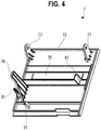
- the opening/closing cover 7 includes an operation lever 79 that projects from the rear surface of the opening/closing cover main body 73 and rotates the printing head 21 and two pressing projections 81 that project from the rear surface of the opening/closing cover main body 73 and press the tape cartridge 100.
- the opening/closing cover 7 includes a pressing projection 83 that projects from the rear surface of the opening/closing cover main body 73 and operates (turns ON) an embedded cover closing detection switch (not shown).
- the check window 75 is formed to be long from side to side and made of a transparent (visible-light transparent) resin formed separately from the opening/closing cover main body 73. Through the check window 75, (a type and a tape remaining amount of the printing tape 102 of) the tape cartridge 100 installed on the cartridge installation portion 5 can be visually checked.
- the pair of journaled pieces 77, the operation lever 79, the two pressing projections 81, and the pressing projection 83 are integrally formed (molded) with the opening/closing cover main body 73 by a resin.
- One of the pressing projections 81 is positioned so as to be in the vicinity of the platen roller 120 of the tape cartridge 100, and the other of the processing projections 81 is positioned so as to be right above the tape detection portion 51.
- the two pressing projections 81 press the tape cartridge 100 so as to be set on the installation base 31 of the cartridge installation portion 5 and prevent the tape cartridge 100 from floating.
- a surface on the near side in the installation direction i.e., on the upper front side of the tape cartridge 100 will be called a "front surface”
- a surface on the back side in the installation direction i.e., on the opposite side of the tape cartridge 100 will be called a "rear surface”
- a side surface on the left side of the tape cartridge 100 will be called a "left side surface”
- a side surface on the right side thereof will be called a “right side surface”
- an arc-shaped side surface on the upper side thereof will be called a "tip end surface”
- a side surface on the lower side thereof will be called a “base end surface.”
- the cartridge casing 130 constitutes the outer shell of the tape cartridge 100 (the shell structure) and has an appearance that is formed in an "L"-shape in plan view and of which the base end at the right side surface slightly projects.
- the cartridge casing 130 is constituted of a lower casing 150 and an upper casing 152, the lower casing 150 and the upper casing 152 being positioned on the back side and the near side, respectively, when the cartridge casing 130 is installed on the cartridge installation portion 5.
- the upper casing 152 is constituted of a transparent resin molded item
- the lower casing 150 is constituted of a non-transparent resin molded item.
- the detected portion 180 corresponding to the tape detection portion 51 is provided at a left corner part on the side of the base end surface (i.e., at a right corner part as seen from the side of the front surface) (see Fig. 6 ).
- the detected portion 180 is constituted at a place corresponding to the plurality of micro switches 51a of the tape detection portion 51, and a plurality of bit patterns is obtained based on the presence or absence of reception holes 180a provided at the place. That is, the bit patterns correspond to a type of the printing tape 102.
- a tape accommodation area 190 in which the tape roll 106 is widely accommodated is constituted.
- the core shaft 192 integrally formed (molded) with the lower casing 150 is provided to stand.
- the core shaft 192 is formed in a cylindrical shape, and the tape roll 106 (the tape core 104) is rotatably journaled in the outer peripheral surface of the core shaft 192.
- a tape guide 194 that guides the fed-out printing tape 102 to the platen roller 120 is integrally formed with the lower casing 150 so as to stand in the vicinity of the platen roller 120. That is, inside the cartridge casing 130, a tape feeding path 196 ranging from the tape roll 106 as a starting point to the tape delivering port 138 via the tape guide 194 and the platen roller 120 is constituted. The printing tape 102 fed out from the tape roll 106 is guided to the platen roller 120 via the tape guide 194 and subjected to printing by the platen roller 120. Then, the printing tape 102 is further guided from the platen roller 120 to the tape delivering port 138.
- the tape roll 106 includes two circular films 198 affixed to both end surfaces of the roll-shaped printing tape 102, besides the printing tape 102 and the tape core 104.
- the two circular films 198 prevent the printing tape 102 wound on the tape core 104 from spreading out.
- a reverse-rotation stop mechanism is embedded in the tape core 104. When the tape cartridge 100 is carried, the reverse rotation of the printing tape 102 is prevented by the reverse-rotation stop mechanism.
- the reverse-rotation stop of the reverse-rotation stop mechanism is released by the positioning projection 41, whereby the feeding of the printing tape 102 is made possible.
- the notched parts of the feeding-out-side bearing portion 202 and the winding-up-side bearing portion 204 formed on the lower casing 150 are each integrally formed with the rotation-stop hooks 206 having the tip end thereof facing the feeding-out-side bearing portion 202 and the winding-up-side bearing portion 204. Further, one and the other of rotation-stop hooks 206 engage with the feeding-out core 112 and the winding-up core 116, respectively, in their rotation stopping state.
- a first ribbon guide 210 that guides the fed-out ink ribbon 110 to the platen roller 120 is integrally formed with the lower casing 150 so as to stand in the vicinity of the feeding-out-side bearing portion 202.
- a plurality of second ribbon guides 212 that guides the going-around of the ink ribbon 110 is integrally formed on the outer peripheral side of the opening peripheral wall portion 164.
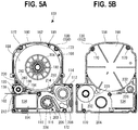
- the ribbon roll 114 includes a circular leaf spring 220 that applies a braking load to the feeding-out core 112, besides the ink ribbon 110 and the feeding-out core 112 (see Fig. 5B ).
- the leaf spring 220 is formed to be wavy in the peripheral direction and interposed between the top wall portion 156 of the upper casing 152 and the feeding-out core 112 in the shaft direction. That is, a rotation braking load is applied to the feeding-out core 112 by the elastic force of the leaf spring 220.
- back tension is applied to the ink ribbon 110 fed out from the winding-up core 116 to prevent slack in the ink ribbon 110.
- the feeding-out core 112 is formed in a cylindrical shape, and a plurality of notches 222 is formed in the peripheral direction at the end thereof on the side of the lower casing 150 (see Fig. 6 ). Further, the rotation-stop hooks 206 engage with or disengage from the plurality of notches 222. Note that the feeding-out-side bearing portion 202 on the side of the lower casing 150 supporting the feeding-out core 112 is constituted of a circular opening while the feeding-out-side bearing portion 202 on the side of the upper casing 152 is constituted of a cylindrical projection portion. Further, the leaf spring 220 is attached to the projection portion (see Fig. 5B about both of the constituents).
- the platen roller 120 supported by the elliptical upper bearing portion 232 and the lower bearing portion 234 is configured to be horizontally movable (slightly movable) between a home position (restraint canceling position) at which the platen roller 120 engages with the platen driving shaft 45 and a holding position (restraint position) at which the platen roller 120 comes in contact with the tape guide 194 with the printing tape 102 held therebetween.
- the fed-out end of the printing tape 102 is in a state of slightly projecting from the tape delivering port 138 to an outside (see Fig. 1 ). If a pressing force or a withdrawing force is falsely applied to the fed-out end of the printing tape 102 at this time, the platen roller 120 pulled by the force is moved to the holding position described above. Thus, the fed-out end of the printing tape 102 is prevented from being withdrawn into the cartridge casing 130 via the tape delivering port 138.
- a fitting portion 236 in which the tip end of the platen supporting shaft 48 fits is formed on the outside of the upper bearing portion 232.
- the fitting portion 236 is constituted of a fitting hole that penetrates the top wall portion 156.
- the fitting portion 236 communicates with the upper bearing portion 232 and is disposed coaxially with the upper bearing portion at the home position described above (that will be described in detail later).
- the platen roller 120 includes a cylindrical roller base body 240 and a rubber roller 242 attached to the outer peripheral surface of the roller base body 240.
- the rubber roller 242 has a length corresponding to the printing head 21 in the shaft direction, and the printing head 21 comes in contact with the rubber roller 242 with the printing tape 102 and the ink ribbon 110 held therebetween when moving to a printing position.
- a spline groove 244 is formed on the inner peripheral surface of the roller base body 240 and engages with the rotation driving shaft 49 of the platen driving shaft 45.
- the rotation force of the platen driving shaft 45 is transmitted to the platen roller 120 to print-feed the printing tape 102 (and the ink ribbon 110).
- the platen driving shaft 45 includes the platen supporting shaft 48 provided to stand on an apparatus frame 260 positioned under the installation base 31 and the rotation driving shaft 49 rotatably supported by the lower portion of the platen supporting shaft 48.
- the rotation driving shaft 49 includes a gear portion 270 constituted of a spur gear and a spline portion 272 integrally formed with the gear portion 270. Further, the gear portion 270 is joined to the tape feeding mechanism portion 25.
- the platen supporting shaft 48 is integrally formed by a straight-shaped shaft main body 280 and a shaft fixation portion 282 communicating with the side of the base end of the shaft main body 280.
- the shaft fixation portion 282 is press-fitted in a lower hole formed on the apparatus frame 260, whereby the platen supporting shaft 48 is fixed to the apparatus frame 260. That is, the platen supporting shaft 48 extending in the attaching/detaching direction of the tape cartridge 100 is fixed to the apparatus frame 260 at one end thereof.
- the platen supporting shaft 48 of the embodiment extends from the apparatus frame 260 so as to be crossed, and the shaft main body 280 penetrates the installation base 31 to be exposed to the inside of the cartridge installation portion 5. Further, the tip end of the platen supporting shaft 48 is chamfered to be substantially the same in height as the head cover 43.
- an installation direction represents a direction from the tip end to the base end of the platen supporting shaft 48 and a removing direction represents a direction opposite to the installation direction
- the platen supporting shaft 48 (the shaft main body 280) extending in the attaching/detaching direction is inserted in the roller base body 240 and the rotation driving shaft 49 engages with the lower end of the roller base body 240. That is, the platen roller 120 is rotatably supported by the platen supporting shaft 48 and rotated and driven by the rotation driving shaft 49 in this state.
- the circular boss portion 302 functions as a portion for preventing the rubber roller 242 from coming off and includes an upper rotation engagement portion 310 rotation-engaging with the upper bearing portion 232 on the side of the tip end thereof.
- the circular engagement portion 304 functions as a portion for inputting rotation power and includes a lower rotation engagement portion 312 rotation-engaging with the lower bearing portion 234 on the side of the base end thereof.
- the platen roller 120 is rotatably supported by the top wall portion 156 (the upper bearing portion 232) of the upper casing 152 and the bottom wall portion 160 (the lower bearing portion 234) of the lower casing 150 in a state of being supported at both ends thereof (i.e., in a state where displacements in both ends of the platen supporting shaft 48 in the direction crossing a direction in which the platen supporting shaft 48 extends are restricted and are not allowed unlimitedly).
- the upper bearing portion 232 on the near side in the installation direction (on the side of the tip end of the platen supporting shaft 48) and the lower bearing portion 234 on the back side in the installation direction (on the side of the rotation driving shaft 49) are formed in the oval (elliptical) shapes in plan view, and the platen roller 120 is supported by the cartridge casing 130 so as to be rotatable and slightly movable (horizontally movable). Note that this slight movement represents the movement of the platen roller 120 with the withdrawn printing tape 102 (a friction force), i.e., the movement in a direction obliquely crossing the tape guide 194. Thus, the printing tape 102 is held between the platen roller 120 and the tape guide 194 to prevent unexpected entanglement with the printing tape 102.
- the fitting portion 236 in which the tip end of (the shaft main body 280 of) the platen supporting shaft 48 fits is formed on the outside of the upper bearing portion 232 on the top wall portion 156 of the upper casing 152.
- the top wall portion 156 has a slightly arising covering wall portion 316 when seen from the direction of the platen supporting shaft 48 of the platen roller 120 (when seen from the side of the tip end to the side of the base end of the platen supporting shaft 48), and the fitting portion 236 is formed at the covering wall portion 316.
- a leading slant surface is provided at the circular margin of the covering wall portion 316 having the fitting portion 236 to reduce the catching of the tape cartridge 100 when the tape cartridge 100 is installed on the cartridge installation portion 5.
- the platen supporting shaft 48 and the fitting portion 236 have a size tolerance that causes no rattling, and the fitting portion 236 holds the tip end of the platen supporting shaft 48 supported at one end thereof on the side of the base end (the lower side) (restricts displacements in the direction crossing the direction in which the platen supporting shaft 48 extends).
- the fitting portion 236 of the tape cartridge 100 installed on the cartridge installation portion 5 fits in the tip end of the platen supporting shaft 48 of the platen driving shaft 45.
- the tip end of the platen supporting shaft 48 supported at one end thereof on the side of the base end is held by the fitting portion 236. That is, only by the installation of the tape cartridge 100 on the cartridge installation portion 5, the platen supporting shaft 48 can be supported at both ends thereof. Accordingly, the platen supporting shaft 48 is allowed to be supported at both ends thereof with the simple structure and the simple operation.
- the printing head 21 and the platen roller 120 can nearly uniformly come in contact with each other with a reduction in the inclination of the platen roller 120. Accordingly, high printing quality can be secured.
- the resonance can be effectively controlled by the fitting portion 236 in such a way as to reduce displacements in the tip end of the platen supporting shaft 48, of which the side of the base end is supported, in the direction crossing the platen supporting shaft 48 (i.e., the displacements in the portion that vibrates in the direction crossing the shaft direction with a displacement having a maximum amplitude if the platen supporting shaft 48 is supported at one end thereof).
- the platen supporting shaft 48 can fit in the fitting portion 236 irrespective of the thickness type of the tape cartridge 100 provided that the platen supporting shaft 48 is formed to have a length corresponding to the tape cartridge 100 having a maximum width with respect to the plurality of types of tape cartridges 100 having a different thickness. Accordingly, the platen supporting shaft 48 can be supported at both ends thereof irrespective of the thickness of the tape cartridge 100 installed on the cartridge installation portion 5.
- the fitting portion 236 can be formed in a bag shape. Thus, the catching of the fitting portion 236 at the front surface of the upper casing 152 can be reduced. In addition, even in the tape printing apparatus 1 in which the tape cartridge 100 is installed based on the upper surface thereof, the fitting portion 236 is not necessarily a through hole.
Landscapes
- Printers Characterized By Their Purpose (AREA)
- Impression-Transfer Materials And Handling Thereof (AREA)
- Handling Of Continuous Sheets Of Paper (AREA)
- Handling Of Sheets (AREA)
Applications Claiming Priority (2)
| Application Number | Priority Date | Filing Date | Title |
|---|---|---|---|
| JP2014060916A JP6134283B2 (ja) | 2014-03-24 | 2014-03-24 | テープカートリッジ |
| PCT/JP2015/058317 WO2015146797A1 (ja) | 2014-03-24 | 2015-03-19 | テープカートリッジ |
Publications (3)
| Publication Number | Publication Date |
|---|---|
| EP3124262A1 true EP3124262A1 (de) | 2017-02-01 |
| EP3124262A4 EP3124262A4 (de) | 2018-03-14 |
| EP3124262B1 EP3124262B1 (de) | 2019-07-24 |
Family
ID=54195318
Family Applications (1)
| Application Number | Title | Priority Date | Filing Date |
|---|---|---|---|
| EP15769961.2A Active EP3124262B1 (de) | 2014-03-24 | 2015-03-19 | Bandkassette |
Country Status (9)
| Country | Link |
|---|---|
| US (3) | US9498994B2 (de) |
| EP (1) | EP3124262B1 (de) |
| JP (1) | JP6134283B2 (de) |
| KR (1) | KR101892528B1 (de) |
| CN (1) | CN106103113B (de) |
| BR (1) | BR112016022091A2 (de) |
| RU (1) | RU2667230C2 (de) |
| TW (2) | TWI665100B (de) |
| WO (1) | WO2015146797A1 (de) |
Families Citing this family (19)
| Publication number | Priority date | Publication date | Assignee | Title |
|---|---|---|---|---|
| BRPI0923680B1 (pt) | 2008-12-25 | 2020-01-28 | Brother Kogyo Kabushiki Kaisha | fita cassete |
| PT2370265E (pt) | 2008-12-25 | 2013-10-04 | Brother Ind Ltd | Cassete de fita e impressora de fita |
| US12296580B2 (en) | 2009-03-31 | 2025-05-13 | Brother Kogyo Kabushiki Kaisha | Tape cassette |
| EP4067095B1 (de) | 2009-03-31 | 2025-08-20 | Brother Kogyo Kabushiki Kaisha | Bandkassette |
| CN104691118B (zh) * | 2009-03-31 | 2017-10-13 | 兄弟工业株式会社 | 带盒 |
| US8641304B2 (en) | 2009-06-30 | 2014-02-04 | Brother Kogyo Kabushiki Kaisha | Tape cassette |
| EP2514600B1 (de) * | 2009-12-16 | 2015-01-21 | Brother Kogyo Kabushiki Kaisha | Bandkassette |
| WO2011080840A1 (ja) | 2009-12-28 | 2011-07-07 | ブラザー工業株式会社 | テープカセット |
| CN106103118B (zh) * | 2014-03-24 | 2018-09-28 | 精工爱普生株式会社 | 带打印装置和带打印系统 |
| US10543703B2 (en) * | 2017-07-31 | 2020-01-28 | Brother Kogyo Kabushiki Kaisha | Tape cassette and tape cassette unit |
| JP7143648B2 (ja) * | 2018-06-28 | 2022-09-29 | セイコーエプソン株式会社 | テープ印刷装置、テープカートリッジおよびテープカートリッジセット |
| JP7279537B2 (ja) * | 2019-06-19 | 2023-05-23 | セイコーエプソン株式会社 | 載置台およびテープ印刷システム |
| JP7314646B2 (ja) * | 2019-06-26 | 2023-07-26 | セイコーエプソン株式会社 | テープ印刷装置 |
| JP7556677B2 (ja) * | 2019-06-26 | 2024-09-26 | セイコーエプソン株式会社 | テープ印刷装置 |
| JP1659863S (de) * | 2019-06-28 | 2020-05-18 | ||
| JP1659818S (de) * | 2019-06-28 | 2020-05-18 | ||
| JP7322638B2 (ja) | 2019-09-30 | 2023-08-08 | ブラザー工業株式会社 | 印刷装置及び印刷用カセット |
| CN110949020B (zh) * | 2019-11-12 | 2021-11-05 | 安庆中船柴油机有限公司 | 一种用于号码管打印的号码管预加热装置 |
| US10850780B1 (en) | 2020-01-23 | 2020-12-01 | William Leo Gross | System for reducing aerodynamic drag forces on a trailer |
Family Cites Families (12)
| Publication number | Priority date | Publication date | Assignee | Title |
|---|---|---|---|---|
| JPS629823A (ja) | 1985-07-05 | 1987-01-17 | Hitachi Zosen Corp | 電解複合研摩方法 |
| US5595447A (en) * | 1992-10-13 | 1997-01-21 | Seiko Epson Corporation | Tape cartridge and printing device having print medium cartridge |
| US5853254A (en) * | 1994-12-15 | 1998-12-29 | Seiko Epson Corporation | Tape cartridge for use in a tape printer |
| JP3629823B2 (ja) * | 1996-06-25 | 2005-03-16 | カシオ計算機株式会社 | 印刷装置 |
| JPH11212428A (ja) * | 1998-01-27 | 1999-08-06 | Ricoh Co Ltd | 画像形成装置 |
| JP3606042B2 (ja) | 1998-03-20 | 2005-01-05 | セイコーエプソン株式会社 | テープカートリッジ装置およびこれを備えたテープ印刷装置 |
| JP3420544B2 (ja) * | 1999-12-03 | 2003-06-23 | セイコーエプソン株式会社 | テープカートリッジ |
| JP3775216B2 (ja) * | 2000-12-14 | 2006-05-17 | セイコーエプソン株式会社 | プラテンおよびこれを備えたテープ印刷装置 |
| KR100569169B1 (ko) * | 2003-02-13 | 2006-04-07 | 세이코 엡슨 가부시키가이샤 | 테이프 인쇄 장치, 라벨 작성 방법, 및 기억매체 |
| GB0423010D0 (en) * | 2004-10-15 | 2004-11-17 | Esselte | Cassette |
| WO2010125114A1 (en) * | 2009-04-28 | 2010-11-04 | Dymo | Cassette for use in a label printer |
| JP2011046142A (ja) | 2009-08-28 | 2011-03-10 | Brother Industries Ltd | テープカセットと印字装置 |
-
2014
- 2014-03-24 JP JP2014060916A patent/JP6134283B2/ja not_active Expired - Fee Related
-
2015
- 2015-03-19 EP EP15769961.2A patent/EP3124262B1/de active Active
- 2015-03-19 CN CN201580016114.8A patent/CN106103113B/zh not_active Expired - Fee Related
- 2015-03-19 WO PCT/JP2015/058317 patent/WO2015146797A1/ja not_active Ceased
- 2015-03-19 KR KR1020167029635A patent/KR101892528B1/ko not_active Expired - Fee Related
- 2015-03-19 TW TW106112817A patent/TWI665100B/zh not_active IP Right Cessation
- 2015-03-19 BR BR112016022091A patent/BR112016022091A2/pt not_active Application Discontinuation
- 2015-03-19 TW TW104108847A patent/TWI592314B/zh not_active IP Right Cessation
- 2015-03-19 RU RU2016141414A patent/RU2667230C2/ru not_active IP Right Cessation
- 2015-06-16 US US14/741,301 patent/US9498994B2/en not_active Expired - Fee Related
-
2016
- 2016-10-18 US US15/296,403 patent/US9884499B2/en not_active Expired - Fee Related
-
2017
- 2017-12-08 US US15/835,728 patent/US20180099514A1/en not_active Abandoned
Also Published As
| Publication number | Publication date |
|---|---|
| RU2016141414A3 (de) | 2018-04-26 |
| CN106103113A (zh) | 2016-11-09 |
| TWI592314B (zh) | 2017-07-21 |
| US9498994B2 (en) | 2016-11-22 |
| KR101892528B1 (ko) | 2018-08-28 |
| RU2016141414A (ru) | 2018-04-26 |
| RU2667230C2 (ru) | 2018-09-17 |
| US20180099514A1 (en) | 2018-04-12 |
| TWI665100B (zh) | 2019-07-11 |
| KR20160138198A (ko) | 2016-12-02 |
| US20150283837A1 (en) | 2015-10-08 |
| EP3124262B1 (de) | 2019-07-24 |
| WO2015146797A1 (ja) | 2015-10-01 |
| US20170036464A1 (en) | 2017-02-09 |
| TW201600354A (zh) | 2016-01-01 |
| JP2015182315A (ja) | 2015-10-22 |
| EP3124262A4 (de) | 2018-03-14 |
| BR112016022091A2 (pt) | 2017-10-31 |
| JP6134283B2 (ja) | 2017-05-24 |
| US9884499B2 (en) | 2018-02-06 |
| TW201725128A (zh) | 2017-07-16 |
| CN106103113B (zh) | 2018-07-10 |
Similar Documents
| Publication | Publication Date | Title |
|---|---|---|
| EP3124262B1 (de) | Bandkassette | |
| US10987959B2 (en) | Tape cartridge | |
| EP3124267B1 (de) | Bandkassette | |
| US10286700B2 (en) | Tape cartridge | |
| US20180043715A1 (en) | Tape cartridge |
Legal Events
| Date | Code | Title | Description |
|---|---|---|---|
| STAA | Information on the status of an ep patent application or granted ep patent |
Free format text: STATUS: THE INTERNATIONAL PUBLICATION HAS BEEN MADE |
|
| PUAI | Public reference made under article 153(3) epc to a published international application that has entered the european phase |
Free format text: ORIGINAL CODE: 0009012 |
|
| STAA | Information on the status of an ep patent application or granted ep patent |
Free format text: STATUS: REQUEST FOR EXAMINATION WAS MADE |
|
| 17P | Request for examination filed |
Effective date: 20161021 |
|
| AK | Designated contracting states |
Kind code of ref document: A1 Designated state(s): AL AT BE BG CH CY CZ DE DK EE ES FI FR GB GR HR HU IE IS IT LI LT LU LV MC MK MT NL NO PL PT RO RS SE SI SK SM TR |
|
| AX | Request for extension of the european patent |
Extension state: BA ME |
|
| DAV | Request for validation of the european patent (deleted) | ||
| DAX | Request for extension of the european patent (deleted) | ||
| A4 | Supplementary search report drawn up and despatched |
Effective date: 20180208 |
|
| RIC1 | Information provided on ipc code assigned before grant |
Ipc: B41J 15/04 20060101AFI20180202BHEP |
|
| REG | Reference to a national code |
Ref country code: DE Ref legal event code: R079 Ref document number: 602015034375 Country of ref document: DE Free format text: PREVIOUS MAIN CLASS: B41J0011040000 Ipc: B41J0015040000 |
|
| GRAP | Despatch of communication of intention to grant a patent |
Free format text: ORIGINAL CODE: EPIDOSNIGR1 |
|
| STAA | Information on the status of an ep patent application or granted ep patent |
Free format text: STATUS: GRANT OF PATENT IS INTENDED |
|
| RIC1 | Information provided on ipc code assigned before grant |
Ipc: B41J 3/407 20060101ALI20190129BHEP Ipc: B41J 15/04 20060101AFI20190129BHEP |
|
| INTG | Intention to grant announced |
Effective date: 20190212 |
|
| GRAS | Grant fee paid |
Free format text: ORIGINAL CODE: EPIDOSNIGR3 |
|
| GRAA | (expected) grant |
Free format text: ORIGINAL CODE: 0009210 |
|
| STAA | Information on the status of an ep patent application or granted ep patent |
Free format text: STATUS: THE PATENT HAS BEEN GRANTED |
|
| AK | Designated contracting states |
Kind code of ref document: B1 Designated state(s): AL AT BE BG CH CY CZ DE DK EE ES FI FR GB GR HR HU IE IS IT LI LT LU LV MC MK MT NL NO PL PT RO RS SE SI SK SM TR |
|
| REG | Reference to a national code |
Ref country code: GB Ref legal event code: FG4D |
|
| REG | Reference to a national code |
Ref country code: CH Ref legal event code: EP |
|
| REG | Reference to a national code |
Ref country code: DE Ref legal event code: R096 Ref document number: 602015034375 Country of ref document: DE |
|
| REG | Reference to a national code |
Ref country code: AT Ref legal event code: REF Ref document number: 1157712 Country of ref document: AT Kind code of ref document: T Effective date: 20190815 |
|
| REG | Reference to a national code |
Ref country code: IE Ref legal event code: FG4D |
|
| REG | Reference to a national code |
Ref country code: NL Ref legal event code: MP Effective date: 20190724 |
|
| REG | Reference to a national code |
Ref country code: LT Ref legal event code: MG4D |
|
| REG | Reference to a national code |
Ref country code: AT Ref legal event code: MK05 Ref document number: 1157712 Country of ref document: AT Kind code of ref document: T Effective date: 20190724 |
|
| PG25 | Lapsed in a contracting state [announced via postgrant information from national office to epo] |
Ref country code: LT Free format text: LAPSE BECAUSE OF FAILURE TO SUBMIT A TRANSLATION OF THE DESCRIPTION OR TO PAY THE FEE WITHIN THE PRESCRIBED TIME-LIMIT Effective date: 20190724 Ref country code: FI Free format text: LAPSE BECAUSE OF FAILURE TO SUBMIT A TRANSLATION OF THE DESCRIPTION OR TO PAY THE FEE WITHIN THE PRESCRIBED TIME-LIMIT Effective date: 20190724 Ref country code: PT Free format text: LAPSE BECAUSE OF FAILURE TO SUBMIT A TRANSLATION OF THE DESCRIPTION OR TO PAY THE FEE WITHIN THE PRESCRIBED TIME-LIMIT Effective date: 20191125 Ref country code: NO Free format text: LAPSE BECAUSE OF FAILURE TO SUBMIT A TRANSLATION OF THE DESCRIPTION OR TO PAY THE FEE WITHIN THE PRESCRIBED TIME-LIMIT Effective date: 20191024 Ref country code: AT Free format text: LAPSE BECAUSE OF FAILURE TO SUBMIT A TRANSLATION OF THE DESCRIPTION OR TO PAY THE FEE WITHIN THE PRESCRIBED TIME-LIMIT Effective date: 20190724 Ref country code: BG Free format text: LAPSE BECAUSE OF FAILURE TO SUBMIT A TRANSLATION OF THE DESCRIPTION OR TO PAY THE FEE WITHIN THE PRESCRIBED TIME-LIMIT Effective date: 20191024 Ref country code: NL Free format text: LAPSE BECAUSE OF FAILURE TO SUBMIT A TRANSLATION OF THE DESCRIPTION OR TO PAY THE FEE WITHIN THE PRESCRIBED TIME-LIMIT Effective date: 20190724 Ref country code: SE Free format text: LAPSE BECAUSE OF FAILURE TO SUBMIT A TRANSLATION OF THE DESCRIPTION OR TO PAY THE FEE WITHIN THE PRESCRIBED TIME-LIMIT Effective date: 20190724 Ref country code: HR Free format text: LAPSE BECAUSE OF FAILURE TO SUBMIT A TRANSLATION OF THE DESCRIPTION OR TO PAY THE FEE WITHIN THE PRESCRIBED TIME-LIMIT Effective date: 20190724 |
|
| PG25 | Lapsed in a contracting state [announced via postgrant information from national office to epo] |
Ref country code: LV Free format text: LAPSE BECAUSE OF FAILURE TO SUBMIT A TRANSLATION OF THE DESCRIPTION OR TO PAY THE FEE WITHIN THE PRESCRIBED TIME-LIMIT Effective date: 20190724 Ref country code: IS Free format text: LAPSE BECAUSE OF FAILURE TO SUBMIT A TRANSLATION OF THE DESCRIPTION OR TO PAY THE FEE WITHIN THE PRESCRIBED TIME-LIMIT Effective date: 20191124 Ref country code: GR Free format text: LAPSE BECAUSE OF FAILURE TO SUBMIT A TRANSLATION OF THE DESCRIPTION OR TO PAY THE FEE WITHIN THE PRESCRIBED TIME-LIMIT Effective date: 20191025 Ref country code: RS Free format text: LAPSE BECAUSE OF FAILURE TO SUBMIT A TRANSLATION OF THE DESCRIPTION OR TO PAY THE FEE WITHIN THE PRESCRIBED TIME-LIMIT Effective date: 20190724 Ref country code: AL Free format text: LAPSE BECAUSE OF FAILURE TO SUBMIT A TRANSLATION OF THE DESCRIPTION OR TO PAY THE FEE WITHIN THE PRESCRIBED TIME-LIMIT Effective date: 20190724 Ref country code: ES Free format text: LAPSE BECAUSE OF FAILURE TO SUBMIT A TRANSLATION OF THE DESCRIPTION OR TO PAY THE FEE WITHIN THE PRESCRIBED TIME-LIMIT Effective date: 20190724 |
|
| PG25 | Lapsed in a contracting state [announced via postgrant information from national office to epo] |
Ref country code: TR Free format text: LAPSE BECAUSE OF FAILURE TO SUBMIT A TRANSLATION OF THE DESCRIPTION OR TO PAY THE FEE WITHIN THE PRESCRIBED TIME-LIMIT Effective date: 20190724 |
|
| PG25 | Lapsed in a contracting state [announced via postgrant information from national office to epo] |
Ref country code: PL Free format text: LAPSE BECAUSE OF FAILURE TO SUBMIT A TRANSLATION OF THE DESCRIPTION OR TO PAY THE FEE WITHIN THE PRESCRIBED TIME-LIMIT Effective date: 20190724 Ref country code: EE Free format text: LAPSE BECAUSE OF FAILURE TO SUBMIT A TRANSLATION OF THE DESCRIPTION OR TO PAY THE FEE WITHIN THE PRESCRIBED TIME-LIMIT Effective date: 20190724 Ref country code: DK Free format text: LAPSE BECAUSE OF FAILURE TO SUBMIT A TRANSLATION OF THE DESCRIPTION OR TO PAY THE FEE WITHIN THE PRESCRIBED TIME-LIMIT Effective date: 20190724 Ref country code: IT Free format text: LAPSE BECAUSE OF FAILURE TO SUBMIT A TRANSLATION OF THE DESCRIPTION OR TO PAY THE FEE WITHIN THE PRESCRIBED TIME-LIMIT Effective date: 20190724 Ref country code: RO Free format text: LAPSE BECAUSE OF FAILURE TO SUBMIT A TRANSLATION OF THE DESCRIPTION OR TO PAY THE FEE WITHIN THE PRESCRIBED TIME-LIMIT Effective date: 20190724 |
|
| PG25 | Lapsed in a contracting state [announced via postgrant information from national office to epo] |
Ref country code: SM Free format text: LAPSE BECAUSE OF FAILURE TO SUBMIT A TRANSLATION OF THE DESCRIPTION OR TO PAY THE FEE WITHIN THE PRESCRIBED TIME-LIMIT Effective date: 20190724 Ref country code: SK Free format text: LAPSE BECAUSE OF FAILURE TO SUBMIT A TRANSLATION OF THE DESCRIPTION OR TO PAY THE FEE WITHIN THE PRESCRIBED TIME-LIMIT Effective date: 20190724 Ref country code: CZ Free format text: LAPSE BECAUSE OF FAILURE TO SUBMIT A TRANSLATION OF THE DESCRIPTION OR TO PAY THE FEE WITHIN THE PRESCRIBED TIME-LIMIT Effective date: 20190724 Ref country code: IS Free format text: LAPSE BECAUSE OF FAILURE TO SUBMIT A TRANSLATION OF THE DESCRIPTION OR TO PAY THE FEE WITHIN THE PRESCRIBED TIME-LIMIT Effective date: 20200224 |
|
| REG | Reference to a national code |
Ref country code: DE Ref legal event code: R097 Ref document number: 602015034375 Country of ref document: DE |
|
| PGFP | Annual fee paid to national office [announced via postgrant information from national office to epo] |
Ref country code: FR Payment date: 20200130 Year of fee payment: 6 |
|
| PLBE | No opposition filed within time limit |
Free format text: ORIGINAL CODE: 0009261 |
|
| STAA | Information on the status of an ep patent application or granted ep patent |
Free format text: STATUS: NO OPPOSITION FILED WITHIN TIME LIMIT |
|
| PG2D | Information on lapse in contracting state deleted |
Ref country code: IS |
|
| 26N | No opposition filed |
Effective date: 20200603 |
|
| PG25 | Lapsed in a contracting state [announced via postgrant information from national office to epo] |
Ref country code: SI Free format text: LAPSE BECAUSE OF FAILURE TO SUBMIT A TRANSLATION OF THE DESCRIPTION OR TO PAY THE FEE WITHIN THE PRESCRIBED TIME-LIMIT Effective date: 20190724 |
|
| PG25 | Lapsed in a contracting state [announced via postgrant information from national office to epo] |
Ref country code: MC Free format text: LAPSE BECAUSE OF FAILURE TO SUBMIT A TRANSLATION OF THE DESCRIPTION OR TO PAY THE FEE WITHIN THE PRESCRIBED TIME-LIMIT Effective date: 20190724 |
|
| REG | Reference to a national code |
Ref country code: CH Ref legal event code: PL |
|
| REG | Reference to a national code |
Ref country code: BE Ref legal event code: MM Effective date: 20200331 |
|
| PG25 | Lapsed in a contracting state [announced via postgrant information from national office to epo] |
Ref country code: LU Free format text: LAPSE BECAUSE OF NON-PAYMENT OF DUE FEES Effective date: 20200319 |
|
| PG25 | Lapsed in a contracting state [announced via postgrant information from national office to epo] |
Ref country code: CH Free format text: LAPSE BECAUSE OF NON-PAYMENT OF DUE FEES Effective date: 20200331 Ref country code: LI Free format text: LAPSE BECAUSE OF NON-PAYMENT OF DUE FEES Effective date: 20200331 Ref country code: IE Free format text: LAPSE BECAUSE OF NON-PAYMENT OF DUE FEES Effective date: 20200319 |
|
| PG25 | Lapsed in a contracting state [announced via postgrant information from national office to epo] |
Ref country code: BE Free format text: LAPSE BECAUSE OF NON-PAYMENT OF DUE FEES Effective date: 20200331 |
|
| GBPC | Gb: european patent ceased through non-payment of renewal fee |
Effective date: 20200319 |
|
| PG25 | Lapsed in a contracting state [announced via postgrant information from national office to epo] |
Ref country code: GB Free format text: LAPSE BECAUSE OF NON-PAYMENT OF DUE FEES Effective date: 20200319 |
|
| PG25 | Lapsed in a contracting state [announced via postgrant information from national office to epo] |
Ref country code: FR Free format text: LAPSE BECAUSE OF NON-PAYMENT OF DUE FEES Effective date: 20210331 |
|
| PG25 | Lapsed in a contracting state [announced via postgrant information from national office to epo] |
Ref country code: MT Free format text: LAPSE BECAUSE OF FAILURE TO SUBMIT A TRANSLATION OF THE DESCRIPTION OR TO PAY THE FEE WITHIN THE PRESCRIBED TIME-LIMIT Effective date: 20190724 Ref country code: CY Free format text: LAPSE BECAUSE OF FAILURE TO SUBMIT A TRANSLATION OF THE DESCRIPTION OR TO PAY THE FEE WITHIN THE PRESCRIBED TIME-LIMIT Effective date: 20190724 |
|
| PG25 | Lapsed in a contracting state [announced via postgrant information from national office to epo] |
Ref country code: MK Free format text: LAPSE BECAUSE OF FAILURE TO SUBMIT A TRANSLATION OF THE DESCRIPTION OR TO PAY THE FEE WITHIN THE PRESCRIBED TIME-LIMIT Effective date: 20190724 |
|
| PGFP | Annual fee paid to national office [announced via postgrant information from national office to epo] |
Ref country code: DE Payment date: 20240130 Year of fee payment: 10 |
|
| REG | Reference to a national code |
Ref country code: DE Ref legal event code: R119 Ref document number: 602015034375 Country of ref document: DE |
|
| PG25 | Lapsed in a contracting state [announced via postgrant information from national office to epo] |
Ref country code: DE Free format text: LAPSE BECAUSE OF NON-PAYMENT OF DUE FEES Effective date: 20251001 |