EP3121333A1 - Rail track support - Google Patents
Rail track support Download PDFInfo
- Publication number
- EP3121333A1 EP3121333A1 EP16001602.8A EP16001602A EP3121333A1 EP 3121333 A1 EP3121333 A1 EP 3121333A1 EP 16001602 A EP16001602 A EP 16001602A EP 3121333 A1 EP3121333 A1 EP 3121333A1
- Authority
- EP
- European Patent Office
- Prior art keywords
- concrete beam
- track
- foundation
- concrete
- elastomer
- Prior art date
- Legal status (The legal status is an assumption and is not a legal conclusion. Google has not performed a legal analysis and makes no representation as to the accuracy of the status listed.)
- Granted
Links
Images


Classifications
-
- E—FIXED CONSTRUCTIONS
- E01—CONSTRUCTION OF ROADS, RAILWAYS, OR BRIDGES
- E01B—PERMANENT WAY; PERMANENT-WAY TOOLS; MACHINES FOR MAKING RAILWAYS OF ALL KINDS
- E01B1/00—Ballastway; Other means for supporting the sleepers or the track; Drainage of the ballastway
- E01B1/002—Ballastless track, e.g. concrete slab trackway, or with asphalt layers
-
- E—FIXED CONSTRUCTIONS
- E01—CONSTRUCTION OF ROADS, RAILWAYS, OR BRIDGES
- E01B—PERMANENT WAY; PERMANENT-WAY TOOLS; MACHINES FOR MAKING RAILWAYS OF ALL KINDS
- E01B1/00—Ballastway; Other means for supporting the sleepers or the track; Drainage of the ballastway
-
- E—FIXED CONSTRUCTIONS
- E01—CONSTRUCTION OF ROADS, RAILWAYS, OR BRIDGES
- E01B—PERMANENT WAY; PERMANENT-WAY TOOLS; MACHINES FOR MAKING RAILWAYS OF ALL KINDS
- E01B19/00—Protection of permanent way against development of dust or against the effect of wind, sun, frost, or corrosion; Means to reduce development of noise
- E01B19/003—Means for reducing the development or propagation of noise
-
- E—FIXED CONSTRUCTIONS
- E01—CONSTRUCTION OF ROADS, RAILWAYS, OR BRIDGES
- E01B—PERMANENT WAY; PERMANENT-WAY TOOLS; MACHINES FOR MAKING RAILWAYS OF ALL KINDS
- E01B2/00—General structure of permanent way
- E01B2/003—Arrangement of tracks on bridges or in tunnels
-
- E—FIXED CONSTRUCTIONS
- E01—CONSTRUCTION OF ROADS, RAILWAYS, OR BRIDGES
- E01B—PERMANENT WAY; PERMANENT-WAY TOOLS; MACHINES FOR MAKING RAILWAYS OF ALL KINDS
- E01B2204/00—Characteristics of the track and its foundations
- E01B2204/01—Elastic layers other than rail-pads, e.g. sleeper-shoes, bituconcrete
Definitions
- the invention relates to a vibration-damping Bahngleisauflagerung whose rails rest by means of sleepers including ballast or track slabs on a concrete beam, and a spring device which consists of metal springs or an elastomer and is located below the track between the concrete beam and a concrete foundation.
- the efficiency of the insulation increases as well as the production cost in the order of the types mentioned.
- the invention has for its object to provide a material, space and cost-saving Brugleisauflagerung with good vibration isolation. It consists in a Brugleisauflagerung of the type mentioned is that in addition to and next to the spring means between the concrete beam and the foundation shock absorbing elements are arranged, which come into parallel with the spring means for action.
- the shock absorbing members may be made of high loss factor viscoelastic material, i. high energy absorption, or consist of hydraulic dampers.
- the viscoelastic material is advantageously a porous plastic having a loss factor of about 0.25 to 0.60, preferably 0.40 to 0.50.
- a partially crystalline PUR elastomer having a high amorphous content is suitably used.
- the shock-absorbing elements in the form of viscoelastic material and the spring means in the form of an elastomer are both arranged in strip form alternately side by side between the bottom of the concrete beam and the foundation so as to give a full-surface bearing ,
- the resilient or shock-absorbing material strips are suitably the same thickness. Different thickness can be compensated by a Aufbetontik according to the difference of the material thicknesses.
- the two strips are preferably applied to a common textile or nonwoven mat.
- the two stripes may be the same thickness and / or the same width; this also simplifies laying and reduces the cost of producing and processing the strips.
- a particularly effective vibration isolation is achieved if each consisting of a layer of viscoelastic material and a layer of a spring device representing elastomer existing blocks are arranged as punctiform interlayers at grid intersection points between the concrete beam and the concrete foundation. Also in this embodiment with Point or individual storage of the concrete beams carrying the rails, the blocks can be expediently applied to a common textile or nonwoven mat.
- An embodiment with a particularly effective as shock-absorbing elements hydraulic dampers provides that in the area directly below the track a spring means in the form of a continuous elastic elastomer layer and on both sides arranged in recesses of the concrete beam rows of shock absorption elements in the form of hydraulic dampers are arranged at the bottom of the concrete foundation and At the top, lean against the top of the concrete beam in alignment with these connected steel girders.
- the steel beams can be integrated in the concrete beams.
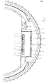
- FIG. 1 a tunnel cross-section with a full-surface superimposed railway track
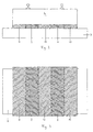
- Fig. 2 schematically a full-surface railroad track suspension in a cross-section
- Fig. 3 the Auflagerung after Fig. 2 in plan view without rails and these supporting concrete beams
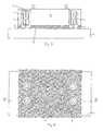
- Fig. 4 schematically a point or Einzelauflagerung a railway track in a cross section
- Fig. 5 the Auflagerung after Fig. 4 in plan view without rails and with indicated concrete beams
- Fig. 6 another embodiment of a point or a single Aufauflagerung in the representation as in Fig. 5 .
- FIG. 7 schematically a further embodiment of a point or individual support in cross-section
- Fig. 8 the Auflagerung after Fig. 7 in top view without rails
- Fig. 9 an embodiment with shock absorbers attached to an existing, only resilient Bahngleisauflagerung.
- Fig. 1 For example, the rails of a railroad track designated 1 are fastened by means of rail fastening 2 on the track plate 3, which is concreted in a longitudinal concrete beam 4, such as reinforced concrete beams.
- a longitudinal concrete beam 4 such as reinforced concrete beams.
- the concrete beam 4 is provided on both sides with upstanding cheeks 6, so that itself these cheeks 6 and the absorber plates 5 are at the level of the rail running surface.
- the concrete beam 4 is supported on the in situ concrete foundation 7 of the tunnel sole via a spring device 8 consisting of elastomeric strip.
- Fig. 1 illustrated Bahngleisauflagerung the prior art.
- the invention begins: The areas not covered by the elastomer strips of the spring device 8 on the underside of the concrete beam 4 are covered by strips 10 of viscoelastic material, which form the shock-absorbing elements.
- the viscoelastic strips 10 have the same thickness as the elastic ones Strip of the spring device 8, they are arranged side by side between the foundation 7 and the concrete beam 4.
- the viscoelastic material has a high loss factor of, for example, 0.4.
- Fig. 2 indicates the rail support Fig. 1 in a schematic cross section
- Fig. 3 a top view Fig. 2 without concrete beams 4 and rails 1.
- Fig. 4 is a section through a point- or single-stored track after the line IV-IV in Fig. 5 , which schematically shows the track suspension of Fig. 4 shows in plan view.
- FIG. 5 Similar plan view of a track suspension of Fig. 6 shows square-shaped block-shaped spring means 8, surrounded by shock-absorbing strips 10.
- the blocks of the spring means 8 and the surrounding strips 10 are formed as point-shaped intermediate layers at grid intersection points between the concrete beam 4 and the foundation 7.
- FIGS. 7 and 8 show a track support with a continuous in the area directly below the concrete beam 4 surface storage of the spring device 8 representing elastomer analogous to 4 and 5
- Fig. 7 is a cross section along the line VII-VII of the plan view of Fig. 8
- On both sides next to the spring device 8 performing layer 4 rows of individual shock absorbers 11 are arranged in the form of hydraulic dampers in the recesses of the concrete beam, which are supported at the bottom of the foundation 7 and at the top of longitudinal steel beams 12 whose top is aligned with the top of the concrete beam 4 and in embedded in the concrete beam 4 and are firmly connected to this.
- Fig. 9 shows an embodiment of the track support in cross section similar Fig. 8 However, with the shock-absorbing elements 11 have been subsequently grown on a equipped only with a spring device 8 in the form of a surface storage Brugleisauflagerung.
- the invention can improve the vibration isolation of an elastic railroad track pad which, via the correct dimensioning of the natural frequency of the oscillating system, adapted to the local conditions, i. the mass of the track supporting concrete beam including track plate and the rigidity of this supporting spring device goes beyond and avoids the costly point storage.
Abstract
Schwingungsdämmende Bahngleisauflagerung, deren Schienen (1) vermittels Schwellen samt Schotterbett oder Gleistragplatten (3) auf einem Betonbalken (4) ruhen, sowie mit einer Federeinrichtung (8), die aus Metallfedern oder einem Elastomer besteht und unterhalb des Gleises zwischen dem Betonbalken und einem Fundament (7) angeordnet ist, wobei zusätzlich zur und neben der Federeinrichtung (8) zwischen dem Betonbalken und dem Fundament Stoßdämpfungselemente (10) angeordnet sind, die parallel mit der Federeinrichtung zur Wirkung gelangen.Vibration-damping Bahngleisauflagerung whose rails (1) by means of sleepers including ballast or track slabs (3) on a concrete beam (4) rest, and with a spring device (8) consisting of metal springs or an elastomer and below the track between the concrete beam and a foundation (7) is arranged, wherein in addition to and next to the spring means (8) between the concrete beam and the foundation shock absorption elements (10) are arranged, which come into parallel with the spring means to the effect.
Description
Die Erfindung betrifft eine schwingungsdämmende Bahngleisauflagerung, deren Schienen vermittels Schwellen samt Schotterbett oder Gleistragplatten auf einem Betonbalken ruhen, sowie einer Federeinrichtung, die aus Metallfedern oder einem Elastomer besteht und unterhalb des Gleises zwischen dem Betonbalken und einem Betonfundament angeordnet ist.The invention relates to a vibration-damping Bahngleisauflagerung whose rails rest by means of sleepers including ballast or track slabs on a concrete beam, and a spring device which consists of metal springs or an elastomer and is located below the track between the concrete beam and a concrete foundation.
Derartige Bahngleisauflagerungen, die vorwiegend in Tunneln zum Vermeiden der Belästigung durch Erschütterungen verwendet werden, haben den Nachteil, daß große Massen des auf dem Ortbeton des Fundamentes federnd abgestützten Betonbalkens eingesetzt werden müssen. Diese sind für eine niedrige Eigenfrequenz der beim Befahren in Schwingung geratenden Masse erforderlich, damit auch niedrige Emissionsfrequenzen gedämpft werden können. Große Massen sind nicht nur aufwendig herzustellen, sondern erfordern auch einen entsprechend großen Tunnelausbruch, der ebenso aufwendig ist.Such Bahngleisauflagerungen, which are mainly used in tunnels to avoid harassment by shocks, have the disadvantage that large masses of resiliently supported on the in-situ concrete of the foundation concrete beam must be used. These are required for a low natural frequency of the vibrating mass when driving, so that even low emission frequencies can be damped. Large masses are not only expensive to produce, but also require a correspondingly large tunnel outbreak, which is just as expensive.
Der Stand der Technik kennt Federeinrichtungen in Form elastischer Flächenlager für den die Schienen tragenden Betonbalken, Streifenlager in Form von längs in Abstand verlaufenden Federeinrichtungen zwischen dem Betonbalken und dem Betonfundament, sowie als Punkt- oder Einzellager ausgebildete Federeinrichtungen, die an Gitterkreuzungspunkten zwischen dem Fundament und der die Schienen tragenden Betonplatte angeordnet sind. Der Wirkungsgrad der Dämmung nimmt ebenso wie der Herstellungsaufwand in der genannten Reihenfolge der Bauarten zu.The prior art known spring means in the form of elastic surface bearing for the rail-carrying concrete beams, strip bearings in the form of longitudinally spaced spring means between the concrete beam and the concrete foundation, as well as point or single bearing spring devices formed at grid intersection points between the foundation and the the rails supporting concrete slab are arranged. The efficiency of the insulation increases as well as the production cost in the order of the types mentioned.
Die Erfindung liegt die Aufgabe zugrunde, eine material-, raum- und aufwandsparende Bahngleisauflagerung mit guter Schwingungsdämmung bereitzustellen. Sie besteht bei einer Bahngleisauflagerung der eingangs erwähnten Art darin, daß zusätzlich zur und neben der Federeinrichtung zwischen dem Betonbalken und dem Fundament Stoßdämpfungselemente angeordnet sind, die parallel mit der Federeinrichtung zur Wirkung gelangen.The invention has for its object to provide a material, space and cost-saving Bahngleisauflagerung with good vibration isolation. It consists in a Bahngleisauflagerung of the type mentioned is that in addition to and next to the spring means between the concrete beam and the foundation shock absorbing elements are arranged, which come into parallel with the spring means for action.
Die Stoßdämpfungselemente können aus viskoelastischem Material mit hohem Verlustfaktor, d.h. hoher Energieabsorption, oder aus Hydraulikdämpfern bestehen.The shock absorbing members may be made of high loss factor viscoelastic material, i. high energy absorption, or consist of hydraulic dampers.
Das viskoelastische Material ist vorteilhaft ein poröser Kunststoff mit einem Verlustfaktor von etwa 0,25 bis 0,60, vorzugsweise von 0,40 bis 0,50. Als solches Material wird zweckmäßig ein teilkristallines PUR-Elastomer mit hohem amorphem Anteil eingesetzt.The viscoelastic material is advantageously a porous plastic having a loss factor of about 0.25 to 0.60, preferably 0.40 to 0.50. As such material, a partially crystalline PUR elastomer having a high amorphous content is suitably used.
Bei einer ersten, besonders einfachen Ausführungsform der erfindungsgemäßen Auflagerung sind die stoßdämpfenden Elemente in Form des viskoelastischen Materials und die Federeinrichtung in Form eines Elastomers beide je in Streifenform abwechselnd nebeneinander zwischen der Unterseite des Betonbalkens und dem Fundament so angeordnet sind, daß sie ein vollflächiges Auflager ergeben. Die federnden oder stoßdämpfenden Materialstreifen sind zweckmäßig gleich dick. Unterschiedliche Dicke kann durch eine Aufbetonschicht entsprechend der Differenz der Materialstärken ausgeglichen werden.In a first, particularly simple embodiment of the Auflagerung invention, the shock-absorbing elements in the form of viscoelastic material and the spring means in the form of an elastomer are both arranged in strip form alternately side by side between the bottom of the concrete beam and the foundation so as to give a full-surface bearing , The resilient or shock-absorbing material strips are suitably the same thickness. Different thickness can be compensated by a Aufbetonschicht according to the difference of the material thicknesses.
Um das Verlegen zu vereinfachen und dabei Fehler zu vermeiden, sind die zweierlei Streifen vorzugsweise auf einer gemeinsamen Textil- oder Vliesmatte aufgebracht. Die zweierlei Streifen können gleich dick und/oder gleich breit sein; auch dies vereinfacht das Verlegen und verbilligt die Herstellung und Verarbeitung der Streifen.To simplify the laying and thereby avoid errors, the two strips are preferably applied to a common textile or nonwoven mat. The two stripes may be the same thickness and / or the same width; this also simplifies laying and reduces the cost of producing and processing the strips.
Eine besonders wirksame Schwingungsdämmung wird erreicht, wenn je aus einer Schicht aus viskoelastischem Material und einer Schicht aus einem die Federeinrichtung darstellenden Elastomer bestehende Blöcke als punktförmige Zwischenlagen an Gitterkreuzungspunkten zwischen dem Betonbalken und dem Betonfundament angeordnet sind. Auch bei dieser Ausführungsform mit Punkt- oder Einzellagerung des die Schienen tragenden Betonbalkens können die Blöcke zweckmäßig auf einer gemeinsamen Textil- oder Vliesmatte aufgebracht sein.A particularly effective vibration isolation is achieved if each consisting of a layer of viscoelastic material and a layer of a spring device representing elastomer existing blocks are arranged as punctiform interlayers at grid intersection points between the concrete beam and the concrete foundation. Also in this embodiment with Point or individual storage of the concrete beams carrying the rails, the blocks can be expediently applied to a common textile or nonwoven mat.
Eine Ausführungsform mit als Stoßdämpfungselemente besonders wirksamen Hydraulikdämpfern sieht vor, daß im Bereich direkt unterhalb des Gleises eine Federeinrichtung in Form einer durchgehenden elastischen Elastomerschicht und beidseitig daneben in Ausnehmungen des Betonbalkens angeordnete Reihen von Stoßdämpfungselementen in Form von Hydraulikdämpfern angeordnet sind, die sich unten am Betonfundament und oben an mit der Oberseite des Betonbalkens fluchtend mit dieser verbundenen Stahlträgern abstützen. Die Stahlträger können in den Betonbalken integriert sein.An embodiment with a particularly effective as shock-absorbing elements hydraulic dampers provides that in the area directly below the track a spring means in the form of a continuous elastic elastomer layer and on both sides arranged in recesses of the concrete beam rows of shock absorption elements in the form of hydraulic dampers are arranged at the bottom of the concrete foundation and At the top, lean against the top of the concrete beam in alignment with these connected steel girders. The steel beams can be integrated in the concrete beams.
Es ist im übrigen auch möglich, eine vorhandene Gleisauflagerung, deren die Gleise tragender Betonbalken lediglich mit einer Federeinrichtung abgestützt ist, mit einer zusätzlichen Dämpfung auszustatten, indem auf dem Betonbalken seitlich an beiden Seiten auskragend Stahlträger mit einer mit der Oberseite des Betonbalkens fluchtenden Oberseite angebaut werden, die mit Reihen sich auf dem Fundament abstützender Stoßdämpfungselemente in Form von Hydraulikdämpfern verbunden sind.It is also possible, moreover, to equip an existing track support, the track of which carrying concrete beams is supported only with a spring device, with additional damping by laterally cantilevered steel beams are mounted on the concrete beams on both sides with a top aligned with the top of the concrete beam top which are connected to rows of shock absorbers supporting the foundation in the form of hydraulic dampers.
Die Erfindung wird anhand in den Zeichnungen dargestellter Ausführungsbeispiele erfindungsgemäßer Bahngleisauflagerungen näher erläutert. In den Zeichnungen zeigen
In
Da dem Modell des Einmassenschwingers folgend die Gleistragplatte 3 zusammen mit dem Betonbalken (4) die schwingende Masse bildet, wird bei den weiteren Figuren die Masse beider Teile als Betonbalken (4) bezeichnet.Since following the model of the single-weight vibrator, the
Um den Betonbalken 4 auch seitlich von dem Fundament 7 der Tunnelsohle zu trennen, werden Seitenmatten 9 eingelegt, die eine kraftschlüssige Verbindung zur Tunnelsohle verhindern. Bis hierher entspricht die in
Wenn es erforderlich ist, für die Elastomerstreifen der Federeinrichtung 8 und die viskoelastischen Streifen 10 unterschiedliche Materialdicken zu verwenden, kann die Differenz durch Aufbetonstreifen einfach ausgeglichen werden.If it is necessary to use different thicknesses of material for the elastomeric strips of the
Die zu
Die
Seitlich an beiden Seiten des die Schienen 1 tragenden Betonbalkens 4 sind an diesem auskragend Stahlträger 12' befestigt, deren Oberseite mit der Oberseite des Betonbalkens 4 fluchtet und die mit Reihen sich auf dem Fundament 7 abstützender Stoßdämpfungselemente 11 in Form von Hydraulikdämpfern verbunden sind.Laterally on both sides of the rails 1 supporting
Die Erfindung kann die Schwingungsdämmung einer elastischen Bahngleisauflagerung verbessern, die über die auf die lokalen Gegebenheiten abgestimmte, richtige Dimensionierung der Eigenfrequenz des schwingenden Systems, d.h. der Masse des das Gleis tragenden Betonbalkens samt Gleistragplatte und der Steifigkeit der diese stützenden Federeinrichtung hinausgeht und die aufwendige Punktlagerung vermeidet.The invention can improve the vibration isolation of an elastic railroad track pad which, via the correct dimensioning of the natural frequency of the oscillating system, adapted to the local conditions, i. the mass of the track supporting concrete beam including track plate and the rigidity of this supporting spring device goes beyond and avoids the costly point storage.
Da bei Schienenbahnen das Verhältnis von Zugüberfahrtsdauer zur nachfolgenden Pausenlänge in der Regel zumindest 1:10 (vorwiegend sogar 1:20) erreicht und 1:5 keinesfalls unterschreitet, wird die bei einem Dämpfungselement erfolgende Energieumwandlung in Wärme kühltechnisch durch die Wärmeleitung des Betons ausreichend beherrscht werden. Eine zusätzliche Wärmeabfuhr über Kühlbleche ist konstruktiv jedoch machbar.Since in railways the ratio of Zugüberfahrtsdauer for subsequent pause length usually at least 1:10 (predominantly even 1:20) reached and 1: 5 by no means falls short, which takes place in a damping element energy conversion into heat cooling technology is sufficiently controlled by the heat conduction of the concrete , An additional heat dissipation via cooling plates is structurally feasible.
Claims (11)
Applications Claiming Priority (1)
| Application Number | Priority Date | Filing Date | Title |
|---|---|---|---|
| ATA485/2015A AT517573A1 (en) | 2015-07-21 | 2015-07-21 | Bahngleisauflagerung |
Publications (2)
| Publication Number | Publication Date |
|---|---|
| EP3121333A1 true EP3121333A1 (en) | 2017-01-25 |
| EP3121333B1 EP3121333B1 (en) | 2018-01-10 |
Family
ID=56511299
Family Applications (1)
| Application Number | Title | Priority Date | Filing Date |
|---|---|---|---|
| EP16001602.8A Revoked EP3121333B1 (en) | 2015-07-21 | 2016-07-21 | Rail track support |
Country Status (3)
| Country | Link |
|---|---|
| EP (1) | EP3121333B1 (en) |
| AT (1) | AT517573A1 (en) |
| DE (1) | DE202016008896U1 (en) |
Cited By (8)
| Publication number | Priority date | Publication date | Assignee | Title |
|---|---|---|---|---|
| CN107858872A (en) * | 2017-12-25 | 2018-03-30 | 洛阳明创矿山冶金设备有限公司 | A kind of subway guide rail structure that automatic pretension can be achieved |
| EP3447190A1 (en) * | 2017-08-21 | 2019-02-27 | Schweizerische Bundesbahnen SBB | Bearing device for railway rails |
| CN109930435A (en) * | 2019-03-13 | 2019-06-25 | 中建三局第一建设工程有限责任公司 | Straddle-type monorail PC track beam construction method in a kind of circular cross section tunnel |
| CN111395074A (en) * | 2020-03-25 | 2020-07-10 | 江苏锡沂钢模有限公司 | Storage battery car runway sleeper for shield tunnel construction |
| RU2733595C1 (en) * | 2020-03-19 | 2020-10-05 | Общество с ограниченной ответственностью "Динамические системы" | Railway track superstructure in tunnel |
| CN112696212A (en) * | 2020-12-31 | 2021-04-23 | 中铁二院工程集团有限责任公司 | Compressible tunnel bottom structure for inhibiting tunnel bottom bulging and construction method |
| CN114960302A (en) * | 2022-04-21 | 2022-08-30 | 中南大学 | Assembled ballastless track structure of high-speed railway and construction method |
| RU216093U1 (en) * | 2022-12-13 | 2023-01-17 | Общество с ограниченной ответственностью "ГАВАРИ РЕЙЛВЕЙС" | RAIL PLATE |
Families Citing this family (2)
| Publication number | Priority date | Publication date | Assignee | Title |
|---|---|---|---|---|
| AT517573A1 (en) | 2015-07-21 | 2017-02-15 | Steinhauser Consulting Eng Zt Gmbh | Bahngleisauflagerung |
| CN110172870A (en) * | 2019-06-04 | 2019-08-27 | 中铁第一勘察设计院集团有限公司 | Beam type is adjustable ballastless track system |
Citations (3)
| Publication number | Priority date | Publication date | Assignee | Title |
|---|---|---|---|---|
| US4616395A (en) * | 1983-06-30 | 1986-10-14 | Perini Corporation | Railroad track fixation method and apparatus |
| EP1783275A1 (en) * | 2004-07-23 | 2007-05-09 | Gerb (Qingdao) Vibration Control Systems Co., Ltd. | A floating slab track bed |
| JP2008303567A (en) * | 2007-06-06 | 2008-12-18 | Kyushu Railway Co | Vibration-isolating ballast track |
Family Cites Families (12)
| Publication number | Priority date | Publication date | Assignee | Title |
|---|---|---|---|---|
| US4303199A (en) | 1978-08-22 | 1981-12-01 | Eisses Jacobus A | Restored vibration isolation for railway tracks |
| DE3022322C2 (en) | 1980-06-13 | 1986-05-15 | Metzeler Kautschuk GmbH, 8000 München | Profile bearing strips made of elastomer material for track troughs |
| DE9116628U1 (en) | 1991-07-09 | 1993-04-15 | Clouth Gummiwerke Ag, 5000 Koeln, De | |
| EP0647738B1 (en) | 1993-10-08 | 2002-05-15 | Alain Serge Charles Lacroix | Box spring device for insulating railway track foundations |
| JPH0882339A (en) | 1994-09-09 | 1996-03-26 | Shimizu Corp | Base isolation structure |
| DE10155183A1 (en) | 2001-11-12 | 2003-07-03 | Bosch Rexroth Ag | Hydraulic spring element |
| DE102008016953A1 (en) | 2008-04-01 | 2009-10-08 | Railone Gmbh | Fixed carriageway for rail vehicles |
| CN101949115B (en) | 2010-09-26 | 2012-05-09 | 成都市新筑路桥机械股份有限公司 | Vibration isolation device for track traffic |
| CN103306168B (en) | 2012-03-13 | 2016-01-20 | 隔而固(青岛)振动控制有限公司 | A kind of prefabricated floating plate railway roadbed and construction method thereof |
| CN103290745B (en) | 2013-05-09 | 2015-05-20 | 隔而固(青岛)振动控制有限公司 | Multifunctional plate end vibration isolation device |
| CN103711045B (en) | 2013-12-19 | 2015-07-15 | 四川大学 | Device for reducing rail vibration damage |
| AT517573A1 (en) | 2015-07-21 | 2017-02-15 | Steinhauser Consulting Eng Zt Gmbh | Bahngleisauflagerung |
-
2015
- 2015-07-21 AT ATA485/2015A patent/AT517573A1/en unknown
-
2016
- 2016-07-21 EP EP16001602.8A patent/EP3121333B1/en not_active Revoked
- 2016-07-21 DE DE202016008896.4U patent/DE202016008896U1/en active Active
Patent Citations (3)
| Publication number | Priority date | Publication date | Assignee | Title |
|---|---|---|---|---|
| US4616395A (en) * | 1983-06-30 | 1986-10-14 | Perini Corporation | Railroad track fixation method and apparatus |
| EP1783275A1 (en) * | 2004-07-23 | 2007-05-09 | Gerb (Qingdao) Vibration Control Systems Co., Ltd. | A floating slab track bed |
| JP2008303567A (en) * | 2007-06-06 | 2008-12-18 | Kyushu Railway Co | Vibration-isolating ballast track |
Cited By (8)
| Publication number | Priority date | Publication date | Assignee | Title |
|---|---|---|---|---|
| EP3447190A1 (en) * | 2017-08-21 | 2019-02-27 | Schweizerische Bundesbahnen SBB | Bearing device for railway rails |
| CN107858872A (en) * | 2017-12-25 | 2018-03-30 | 洛阳明创矿山冶金设备有限公司 | A kind of subway guide rail structure that automatic pretension can be achieved |
| CN109930435A (en) * | 2019-03-13 | 2019-06-25 | 中建三局第一建设工程有限责任公司 | Straddle-type monorail PC track beam construction method in a kind of circular cross section tunnel |
| RU2733595C1 (en) * | 2020-03-19 | 2020-10-05 | Общество с ограниченной ответственностью "Динамические системы" | Railway track superstructure in tunnel |
| CN111395074A (en) * | 2020-03-25 | 2020-07-10 | 江苏锡沂钢模有限公司 | Storage battery car runway sleeper for shield tunnel construction |
| CN112696212A (en) * | 2020-12-31 | 2021-04-23 | 中铁二院工程集团有限责任公司 | Compressible tunnel bottom structure for inhibiting tunnel bottom bulging and construction method |
| CN114960302A (en) * | 2022-04-21 | 2022-08-30 | 中南大学 | Assembled ballastless track structure of high-speed railway and construction method |
| RU216093U1 (en) * | 2022-12-13 | 2023-01-17 | Общество с ограниченной ответственностью "ГАВАРИ РЕЙЛВЕЙС" | RAIL PLATE |
Also Published As
| Publication number | Publication date |
|---|---|
| AT517573A1 (en) | 2017-02-15 |
| DE202016008896U1 (en) | 2020-06-30 |
| EP3121333B1 (en) | 2018-01-10 |
Similar Documents
| Publication | Publication Date | Title |
|---|---|---|
| EP3121333B1 (en) | Rail track support | |
| DE2126158C3 (en) | Damping pad for traffic routes used by motor vehicles | |
| WO2009121323A1 (en) | Fixed track for rail vehicles | |
| DE3937086A1 (en) | DEVICE FOR STORING RAILS FOR RAIL VEHICLES | |
| EP1846617B1 (en) | Level crossing | |
| DE4439894A1 (en) | Track superstructure | |
| DE102006062638A1 (en) | Track system for rail-bound vehicle i.e. magnetic levitation vehicle, has springs pre-loaded about measure during unloaded condition of beams, where measure is approximately smaller than another measure yielded during loaded condition | |
| EP3447190B1 (en) | Bearing device for a railway system | |
| DE3631492A1 (en) | Reduction of the structure-borne noise on the rails of a railway track | |
| EP1039030A1 (en) | Ballastless railway system | |
| AT409641B (en) | Ballastless superstructure with prefabricated concrete support plates as well as a procedure for the replacement of the same | |
| EP1258563B1 (en) | Ballastless railway track with elastically supported sound absorber elements | |
| EP0767275A1 (en) | Sound absorber for ballastless railway superstructure | |
| AT404742B (en) | TRACK WITH RAILS FOR RAILWAY VEHICLES | |
| DE1964039A1 (en) | Elastic element for mounting rails or sleepers | |
| DE102006028740A1 (en) | Rail bed for rail of railway track on continuous substructure, has damping elements arranged between rail base and substructure, casting compound over length of track between rail head and surrounding construction material at closed tracks | |
| AT411694B (en) | DEVICE FOR THE ELASTIC STORAGE OF A RILLED RAIL | |
| DE2901283A1 (en) | Railway track superstructure concrete support - has support slabs, intermediate layers and elastic inlay on troughed base | |
| DE202007018656U1 (en) | Embedded gravel superstructure | |
| DE10301231B3 (en) | Superstructure guided over viaducts for rail-bound vehicles | |
| EP2817456A1 (en) | Noise reduction device | |
| DE2617386A1 (en) | Outdoor panelled noise-screening wall - is mounted on I - section uprights with interlocking superimposed rows of insulation panels | |
| DE102008044675A1 (en) | Vibration protection for railway permanent way, has lateral force peg on joints in ground plate | |
| WO2007147581A2 (en) | Continuous elastic rail bed | |
| DE1922055C3 (en) | Railway superstructure with a rigid, trough-like plate that forms the bedding |
Legal Events
| Date | Code | Title | Description |
|---|---|---|---|
| REG | Reference to a national code |
Ref country code: DE Ref legal event code: R138 Ref document number: 202016008896 Country of ref document: DE Free format text: GERMAN DOCUMENT NUMBER IS 502016000450 |
|
| PUAI | Public reference made under article 153(3) epc to a published international application that has entered the european phase |
Free format text: ORIGINAL CODE: 0009012 |
|
| 17P | Request for examination filed |
Effective date: 20160721 |
|
| AK | Designated contracting states |
Kind code of ref document: A1 Designated state(s): AL AT BE BG CH CY CZ DE DK EE ES FI FR GB GR HR HU IE IS IT LI LT LU LV MC MK MT NL NO PL PT RO RS SE SI SK SM TR |
|
| AX | Request for extension of the european patent |
Extension state: BA ME |
|
| RIC1 | Information provided on ipc code assigned before grant |
Ipc: E01B 2/00 20060101ALI20170725BHEP Ipc: E01B 19/00 20060101AFI20170725BHEP |
|
| GRAP | Despatch of communication of intention to grant a patent |
Free format text: ORIGINAL CODE: EPIDOSNIGR1 |
|
| INTG | Intention to grant announced |
Effective date: 20170913 |
|
| GRAS | Grant fee paid |
Free format text: ORIGINAL CODE: EPIDOSNIGR3 |
|
| GRAA | (expected) grant |
Free format text: ORIGINAL CODE: 0009210 |
|
| AK | Designated contracting states |
Kind code of ref document: B1 Designated state(s): AL AT BE BG CH CY CZ DE DK EE ES FI FR GB GR HR HU IE IS IT LI LT LU LV MC MK MT NL NO PL PT RO RS SE SI SK SM TR |
|
| REG | Reference to a national code |
Ref country code: CH Ref legal event code: EP Ref country code: AT Ref legal event code: REF Ref document number: 962564 Country of ref document: AT Kind code of ref document: T Effective date: 20180115 |
|
| REG | Reference to a national code |
Ref country code: IE Ref legal event code: FG4D Free format text: LANGUAGE OF EP DOCUMENT: GERMAN |
|
| REG | Reference to a national code |
Ref country code: DE Ref legal event code: R096 Ref document number: 502016000450 Country of ref document: DE |
|
| REG | Reference to a national code |
Ref country code: CH Ref legal event code: NV Representative=s name: ISLER AND PEDRAZZINI AG, CH |
|
| REG | Reference to a national code |
Ref country code: NL Ref legal event code: MP Effective date: 20180110 |
|
| REG | Reference to a national code |
Ref country code: FR Ref legal event code: PLFP Year of fee payment: 3 |
|
| PG25 | Lapsed in a contracting state [announced via postgrant information from national office to epo] |
Ref country code: NL Free format text: LAPSE BECAUSE OF FAILURE TO SUBMIT A TRANSLATION OF THE DESCRIPTION OR TO PAY THE FEE WITHIN THE PRESCRIBED TIME-LIMIT Effective date: 20180110 |
|
| PG25 | Lapsed in a contracting state [announced via postgrant information from national office to epo] |
Ref country code: CY Free format text: LAPSE BECAUSE OF FAILURE TO SUBMIT A TRANSLATION OF THE DESCRIPTION OR TO PAY THE FEE WITHIN THE PRESCRIBED TIME-LIMIT Effective date: 20180110 Ref country code: LT Free format text: LAPSE BECAUSE OF FAILURE TO SUBMIT A TRANSLATION OF THE DESCRIPTION OR TO PAY THE FEE WITHIN THE PRESCRIBED TIME-LIMIT Effective date: 20180110 Ref country code: FI Free format text: LAPSE BECAUSE OF FAILURE TO SUBMIT A TRANSLATION OF THE DESCRIPTION OR TO PAY THE FEE WITHIN THE PRESCRIBED TIME-LIMIT Effective date: 20180110 Ref country code: NO Free format text: LAPSE BECAUSE OF FAILURE TO SUBMIT A TRANSLATION OF THE DESCRIPTION OR TO PAY THE FEE WITHIN THE PRESCRIBED TIME-LIMIT Effective date: 20180410 Ref country code: HR Free format text: LAPSE BECAUSE OF FAILURE TO SUBMIT A TRANSLATION OF THE DESCRIPTION OR TO PAY THE FEE WITHIN THE PRESCRIBED TIME-LIMIT Effective date: 20180110 Ref country code: ES Free format text: LAPSE BECAUSE OF FAILURE TO SUBMIT A TRANSLATION OF THE DESCRIPTION OR TO PAY THE FEE WITHIN THE PRESCRIBED TIME-LIMIT Effective date: 20180110 |
|
| PG25 | Lapsed in a contracting state [announced via postgrant information from national office to epo] |
Ref country code: RS Free format text: LAPSE BECAUSE OF FAILURE TO SUBMIT A TRANSLATION OF THE DESCRIPTION OR TO PAY THE FEE WITHIN THE PRESCRIBED TIME-LIMIT Effective date: 20180110 Ref country code: SE Free format text: LAPSE BECAUSE OF FAILURE TO SUBMIT A TRANSLATION OF THE DESCRIPTION OR TO PAY THE FEE WITHIN THE PRESCRIBED TIME-LIMIT Effective date: 20180110 Ref country code: LV Free format text: LAPSE BECAUSE OF FAILURE TO SUBMIT A TRANSLATION OF THE DESCRIPTION OR TO PAY THE FEE WITHIN THE PRESCRIBED TIME-LIMIT Effective date: 20180110 Ref country code: GR Free format text: LAPSE BECAUSE OF FAILURE TO SUBMIT A TRANSLATION OF THE DESCRIPTION OR TO PAY THE FEE WITHIN THE PRESCRIBED TIME-LIMIT Effective date: 20180411 Ref country code: PL Free format text: LAPSE BECAUSE OF FAILURE TO SUBMIT A TRANSLATION OF THE DESCRIPTION OR TO PAY THE FEE WITHIN THE PRESCRIBED TIME-LIMIT Effective date: 20180110 Ref country code: IS Free format text: LAPSE BECAUSE OF FAILURE TO SUBMIT A TRANSLATION OF THE DESCRIPTION OR TO PAY THE FEE WITHIN THE PRESCRIBED TIME-LIMIT Effective date: 20180510 Ref country code: BG Free format text: LAPSE BECAUSE OF FAILURE TO SUBMIT A TRANSLATION OF THE DESCRIPTION OR TO PAY THE FEE WITHIN THE PRESCRIBED TIME-LIMIT Effective date: 20180410 |
|
| PG25 | Lapsed in a contracting state [announced via postgrant information from national office to epo] |
Ref country code: MT Free format text: LAPSE BECAUSE OF FAILURE TO SUBMIT A TRANSLATION OF THE DESCRIPTION OR TO PAY THE FEE WITHIN THE PRESCRIBED TIME-LIMIT Effective date: 20180110 |
|
| REG | Reference to a national code |
Ref country code: DE Ref legal event code: R026 Ref document number: 502016000450 Country of ref document: DE |
|
| PLBI | Opposition filed |
Free format text: ORIGINAL CODE: 0009260 |
|
| PG25 | Lapsed in a contracting state [announced via postgrant information from national office to epo] |
Ref country code: AL Free format text: LAPSE BECAUSE OF FAILURE TO SUBMIT A TRANSLATION OF THE DESCRIPTION OR TO PAY THE FEE WITHIN THE PRESCRIBED TIME-LIMIT Effective date: 20180110 Ref country code: IT Free format text: LAPSE BECAUSE OF FAILURE TO SUBMIT A TRANSLATION OF THE DESCRIPTION OR TO PAY THE FEE WITHIN THE PRESCRIBED TIME-LIMIT Effective date: 20180110 Ref country code: EE Free format text: LAPSE BECAUSE OF FAILURE TO SUBMIT A TRANSLATION OF THE DESCRIPTION OR TO PAY THE FEE WITHIN THE PRESCRIBED TIME-LIMIT Effective date: 20180110 Ref country code: RO Free format text: LAPSE BECAUSE OF FAILURE TO SUBMIT A TRANSLATION OF THE DESCRIPTION OR TO PAY THE FEE WITHIN THE PRESCRIBED TIME-LIMIT Effective date: 20180110 |
|
| 26 | Opposition filed |
Opponent name: PORR BAU GMBH Effective date: 20181009 |
|
| PG25 | Lapsed in a contracting state [announced via postgrant information from national office to epo] |
Ref country code: SK Free format text: LAPSE BECAUSE OF FAILURE TO SUBMIT A TRANSLATION OF THE DESCRIPTION OR TO PAY THE FEE WITHIN THE PRESCRIBED TIME-LIMIT Effective date: 20180110 Ref country code: CZ Free format text: LAPSE BECAUSE OF FAILURE TO SUBMIT A TRANSLATION OF THE DESCRIPTION OR TO PAY THE FEE WITHIN THE PRESCRIBED TIME-LIMIT Effective date: 20180110 Ref country code: SM Free format text: LAPSE BECAUSE OF FAILURE TO SUBMIT A TRANSLATION OF THE DESCRIPTION OR TO PAY THE FEE WITHIN THE PRESCRIBED TIME-LIMIT Effective date: 20180110 Ref country code: DK Free format text: LAPSE BECAUSE OF FAILURE TO SUBMIT A TRANSLATION OF THE DESCRIPTION OR TO PAY THE FEE WITHIN THE PRESCRIBED TIME-LIMIT Effective date: 20180110 |
|
| PLAX | Notice of opposition and request to file observation + time limit sent |
Free format text: ORIGINAL CODE: EPIDOSNOBS2 |
|
| PG25 | Lapsed in a contracting state [announced via postgrant information from national office to epo] |
Ref country code: SI Free format text: LAPSE BECAUSE OF FAILURE TO SUBMIT A TRANSLATION OF THE DESCRIPTION OR TO PAY THE FEE WITHIN THE PRESCRIBED TIME-LIMIT Effective date: 20180110 |
|
| PG25 | Lapsed in a contracting state [announced via postgrant information from national office to epo] |
Ref country code: MC Free format text: LAPSE BECAUSE OF FAILURE TO SUBMIT A TRANSLATION OF THE DESCRIPTION OR TO PAY THE FEE WITHIN THE PRESCRIBED TIME-LIMIT Effective date: 20180110 Ref country code: LU Free format text: LAPSE BECAUSE OF NON-PAYMENT OF DUE FEES Effective date: 20180721 |
|
| REG | Reference to a national code |
Ref country code: BE Ref legal event code: MM Effective date: 20180731 |
|
| REG | Reference to a national code |
Ref country code: IE Ref legal event code: MM4A |
|
| PG25 | Lapsed in a contracting state [announced via postgrant information from national office to epo] |
Ref country code: IE Free format text: LAPSE BECAUSE OF NON-PAYMENT OF DUE FEES Effective date: 20180721 |
|
| PLBB | Reply of patent proprietor to notice(s) of opposition received |
Free format text: ORIGINAL CODE: EPIDOSNOBS3 |
|
| PG25 | Lapsed in a contracting state [announced via postgrant information from national office to epo] |
Ref country code: BE Free format text: LAPSE BECAUSE OF NON-PAYMENT OF DUE FEES Effective date: 20180731 |
|
| PGFP | Annual fee paid to national office [announced via postgrant information from national office to epo] |
Ref country code: DE Payment date: 20190731 Year of fee payment: 4 Ref country code: FR Payment date: 20190729 Year of fee payment: 4 |
|
| PGFP | Annual fee paid to national office [announced via postgrant information from national office to epo] |
Ref country code: CH Payment date: 20190712 Year of fee payment: 4 |
|
| REG | Reference to a national code |
Ref country code: DE Ref legal event code: R064 Ref document number: 502016000450 Country of ref document: DE Ref country code: DE Ref legal event code: R103 Ref document number: 502016000450 Country of ref document: DE |
|
| PG25 | Lapsed in a contracting state [announced via postgrant information from national office to epo] |
Ref country code: TR Free format text: LAPSE BECAUSE OF FAILURE TO SUBMIT A TRANSLATION OF THE DESCRIPTION OR TO PAY THE FEE WITHIN THE PRESCRIBED TIME-LIMIT Effective date: 20180110 |
|
| RDAF | Communication despatched that patent is revoked |
Free format text: ORIGINAL CODE: EPIDOSNREV1 |
|
| PG25 | Lapsed in a contracting state [announced via postgrant information from national office to epo] |
Ref country code: PT Free format text: LAPSE BECAUSE OF FAILURE TO SUBMIT A TRANSLATION OF THE DESCRIPTION OR TO PAY THE FEE WITHIN THE PRESCRIBED TIME-LIMIT Effective date: 20180110 |
|
| PG25 | Lapsed in a contracting state [announced via postgrant information from national office to epo] |
Ref country code: MK Free format text: LAPSE BECAUSE OF NON-PAYMENT OF DUE FEES Effective date: 20180110 Ref country code: HU Free format text: LAPSE BECAUSE OF FAILURE TO SUBMIT A TRANSLATION OF THE DESCRIPTION OR TO PAY THE FEE WITHIN THE PRESCRIBED TIME-LIMIT; INVALID AB INITIO Effective date: 20160721 |
|
| RDAG | Patent revoked |
Free format text: ORIGINAL CODE: 0009271 |
|
| STAA | Information on the status of an ep patent application or granted ep patent |
Free format text: STATUS: PATENT REVOKED |
|
| REG | Reference to a national code |
Ref country code: CH Ref legal event code: PL |
|
| REG | Reference to a national code |
Ref country code: FI Ref legal event code: MGE |
|
| 27W | Patent revoked |
Effective date: 20200304 |
|
| GBPR | Gb: patent revoked under art. 102 of the ep convention designating the uk as contracting state |
Effective date: 20200304 |
|
| REG | Reference to a national code |
Ref country code: AT Ref legal event code: MA03 Ref document number: 962564 Country of ref document: AT Kind code of ref document: T Effective date: 20200304 |