EP3119082B1 - Head-mounted display - Google Patents
Head-mounted display Download PDFInfo
- Publication number
- EP3119082B1 EP3119082B1 EP15761982.6A EP15761982A EP3119082B1 EP 3119082 B1 EP3119082 B1 EP 3119082B1 EP 15761982 A EP15761982 A EP 15761982A EP 3119082 B1 EP3119082 B1 EP 3119082B1
- Authority
- EP
- European Patent Office
- Prior art keywords
- fastening band
- head
- user
- mounted display
- display unit
- Prior art date
- Legal status (The legal status is an assumption and is not a legal conclusion. Google has not performed a legal analysis and makes no representation as to the accuracy of the status listed.)
- Active
Links
Images


Classifications
-
- G—PHYSICS
- G02—OPTICS
- G02B—OPTICAL ELEMENTS, SYSTEMS OR APPARATUS
- G02B27/00—Optical systems or apparatus not provided for by any of the groups G02B1/00 - G02B26/00, G02B30/00
- G02B27/02—Viewing or reading apparatus
- G02B27/028—Viewing or reading apparatus characterised by the supporting structure
-
- G—PHYSICS
- G02—OPTICS
- G02B—OPTICAL ELEMENTS, SYSTEMS OR APPARATUS
- G02B27/00—Optical systems or apparatus not provided for by any of the groups G02B1/00 - G02B26/00, G02B30/00
- G02B27/01—Head-up displays
- G02B27/017—Head mounted
- G02B27/0176—Head mounted characterised by mechanical features
-
- G—PHYSICS
- G02—OPTICS
- G02B—OPTICAL ELEMENTS, SYSTEMS OR APPARATUS
- G02B27/00—Optical systems or apparatus not provided for by any of the groups G02B1/00 - G02B26/00, G02B30/00
- G02B27/02—Viewing or reading apparatus
- G02B27/022—Viewing apparatus
-
- G—PHYSICS
- G02—OPTICS
- G02B—OPTICAL ELEMENTS, SYSTEMS OR APPARATUS
- G02B7/00—Mountings, adjusting means, or light-tight connections, for optical elements
- G02B7/02—Mountings, adjusting means, or light-tight connections, for optical elements for lenses
- G02B7/021—Mountings, adjusting means, or light-tight connections, for optical elements for lenses for more than one lens
-
- G—PHYSICS
- G09—EDUCATION; CRYPTOGRAPHY; DISPLAY; ADVERTISING; SEALS
- G09G—ARRANGEMENTS OR CIRCUITS FOR CONTROL OF INDICATING DEVICES USING STATIC MEANS TO PRESENT VARIABLE INFORMATION
- G09G5/00—Control arrangements or circuits for visual indicators common to cathode-ray tube indicators and other visual indicators
-
- G—PHYSICS
- G02—OPTICS
- G02B—OPTICAL ELEMENTS, SYSTEMS OR APPARATUS
- G02B27/00—Optical systems or apparatus not provided for by any of the groups G02B1/00 - G02B26/00, G02B30/00
- G02B27/01—Head-up displays
- G02B27/0149—Head-up displays characterised by mechanical features
- G02B2027/0154—Head-up displays characterised by mechanical features with movable elements
- G02B2027/0158—Head-up displays characterised by mechanical features with movable elements with adjustable nose pad
-
- G—PHYSICS
- G02—OPTICS
- G02B—OPTICAL ELEMENTS, SYSTEMS OR APPARATUS
- G02B27/00—Optical systems or apparatus not provided for by any of the groups G02B1/00 - G02B26/00, G02B30/00
- G02B27/01—Head-up displays
- G02B27/0149—Head-up displays characterised by mechanical features
- G02B2027/0154—Head-up displays characterised by mechanical features with movable elements
- G02B2027/0159—Head-up displays characterised by mechanical features with movable elements with mechanical means other than scaning means for positioning the whole image
Definitions
- the present invention relates to a head-mounted display.
- the HMD includes a display unit having a display device for being placed in front of the eyes of the user and a mount to be mounted on the head of the user, the mount supporting the display unit.
- Some HMDs have a fastening band for sandwiching the head of the user along the anterior-posterior directions (e.g., Japanese Patent Laid-open No. Hei 09-304724 ).
- Other previously proposed arrangements are disclosed in WO 2004/049850 A1 and EP 2 685 712 A1 .
- Some of the HMDs have a mechanism incorporated in the fastening band for adjusting the length of the fastening band.
- the HMD When the user matches the length of the fastening band to the size of its own head, the HMD is stably supported on the head.
- the conventional HMDs have a problem in that the process of adjusting the length of the fastening band is cumbersome. For example, if the length of the fastening band does not fit the head of the user, then the user attempts to adjust the length of the fastening band while the HMD is being mounted on the head. However, since the HMD tends to change in position or attitude during the adjusting process, the adjusting process becomes cumbersome.
- a head-mounted display according to the definition of independent claim 1.
- the head-mounted display thus constructed allows the lengths of the fastening bands to be adjusted easily and can be mounted on the head of the user with increased stability.
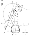
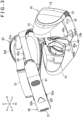
- FIGS. 1 through 3 are views illustrating a head-mounted display 1 according to the embodiment of the present invention (the head-mounted display will hereinafter be referred to as "HMD").
- FIG. 1 is a perspective view
- FIG. 2 is a side elevational view
- FIG. 3 is a perspective view of the HMD 1 as viewed from an angle different from that of FIG. 1 .
- FIG. 4 is a set of views illustrating a rear support 22a of a second fastening band 22 to be described later, FIG. 4(a) being a view of a rear side of the rear support 22a and
- FIG. 4(b) a view illustrating a length adjusting mechanism M1 for the second fastening band 22.
- Y1 and Y2 illustrated in the above figures represent an anterior direction and a posterior direction, respectively, X1 and X2 a leftward direction and a rightward direction, respectively, and Z1 and Z2 an upward direction and a downward direction, respectively.
- the HMD 1 has a display unit 10 including a display device 11 (see FIG. 2 ) on its front side.
- the display device 11 displays three-dimensional images.
- the display device 11 displays an image for the right eye in its right area and an image for the left eye in its left area.
- the display device 11 may display three-dimensional images in a frame sequential format.
- the images displayed by the display device 11 are not limited to three-dimensional images, but may be two-dimensional images.
- the display device 11 may include a liquid crystal display device or an organic electroluminescence (EL) display device, but is not limited to any particular types.
- EL organic electroluminescence
- the fastening bands 21 and 22 extend rearwardly from the front support 23.
- the front support 23 and the first fastening band 21 are of an annular shape
- the front support 23 and the second fastening band 22 are also of an annular shape.
- the user can adjust the length of the second fastening band 22 using its both hands. Furthermore, as the second fastening band 22 is made of a material less expandable than the first fastening band 21, the second fastening band 22 is mounted on the head of the user with increased stability.
- the first fastening band 21 is made of an elastically expandable material in its entirety. According to another example of the HMD 1, only a portion of the first fastening band 21 may be made of an elastically expandable material so that the first fastening band 21 can be expanded in its lengthwise direction.
- the first fastening band 21 may have an unexpandable portion (a portion held against the rear side of the head of the user) in its rear portion, and side portions (portions held against the right and left sides of the head of the user) made of an expandable material.
- the second fastening band 22 has the mechanism M1 for adjusting the length thereof (the mechanism M1 will hereinafter be referred to as "length adjusting mechanism").
- the second fastening band 22 has a rear support 22a in its rear portion which is held against the rear side of the head of the user.
- the rear support 22a has a case 22h housing the length adjusting mechanism M1 (see FIG. 4(b) ) therein.
- the rear support 22a preferably has a cushion 22b (see FIG. 1 ) on an inner surface thereof (a surface to be held against the rear side of the head of the user).
- the second fastening band 22 in the example described herein has left and right frames 22c.
- the frames 22c are made of the material (e.g., plastics) which is less expandable than the material of the first fastening band 21, as described above.
- the left and right frames 22c extend from the front side to rear side of the HMD 1, and are connected respectively to the left and right ends of the rear support 22a.
- the frames 22c extend rearwardly from the right and left sides of the front support 23 and have rear portions fitted in the case 22h of the rear support 22a.
- the length adjusting mechanism M1 is preferably arranged such that the rear support 22a will move equally with respect to the left and right frames 22c. With this arrangement, the position of the rear support 22a is prevented from being shifted to the right or left.
- racks 22d are formed on rear portions of the frames 22c.
- the rack 22d of the right frame 22c and the rack 22d of the left frame 22c are disposed so as to face each other in the vertical, namely up-down directions.
- the rear support 22a includes a rotatable operating member 22e (the operating member 22e will hereinafter be referred to as "length adjusting member").
- the length adjusting member 22e is disposed between the racks 22d of the two frames 22c, and a gear (not illustrated) engaging the racks 22d is coupled to the length adjusting member 22e.
- a gear (not illustrated) engaging the racks 22d is coupled to the length adjusting member 22e.
- the rear support 22a moves equally with respect to the left and right frames 22c, causing the right and left portions of the second fastening band 22 to contract or expand equally.
- the rear support 22a moves along the anterior-posterior directions equally with respect to the left and right frames 22c.
- the length adjusting member 22e is coupled to both of the two frames 22c. Specifically, the gear of the length adjusting member 22e is held in engagement with both of the gears of the two frames 22c.
- the length adjusting mechanism M1 should preferably have a stopper mechanism for allowing the gear of the length adjusting member 22e to rotate in a direction to contract the frames 22c and locking the gear against rotation in the opposite direction.
- the length adjusting mechanism M1 should also preferably have an operating member (hereinafter referred to as "stopper canceling member") for canceling the locking of the gear against rotation (stopper) by the stopper mechanism in response to an operation of the user.
- stopper canceling member an operating member for canceling the locking of the gear against rotation (stopper) by the stopper mechanism in response to an operation of the user.
- the rear support 22a includes a stopper canceling member 22f exposed on its rear surface.
- the stopper canceling member 22f is coupled to a stopper which is held in engagement with the gear disposed between the racks 22d for preventing the gear from rotating. The stopper is released out of engagement with the gear when the stopper canceling member 22f is operated (pushed or slid).
- the first fastening band 21 should also preferably be adjustable in length.
- a length adjusting mechanism for the first fastening band 21 may include a surface fastener, a buckle, or a ratchet mechanism, for example.
- the length adjusting mechanism is provided on each of the right and left sides of the first fastening band 21, thereby preventing the elastic force of the first fastening band 21 from becoming uneven on the right and left sides of the first fastening band 21.
- the foremost portion of the first fastening band 21 is supported by a pin (not illustrated) mounted on the front support 23, and the first fastening band 21 has an adjuster 21a reversed rearwardly and folded back from the pin.
- the adjuster 21a is detachably disposed on a side of the first fastening band 21.
- a surface fastener for example, is attached to the side of the side of the first fastening band 21 and the adjuster 21a.
- the HMD 1 has the front support 23 as described above.
- the front support 23 is coupled to an upper portion of the display unit 10.
- the front support 23 extends upwardly and rearwardly obliquely from the display unit 10.
- the front support 23 is held against the forehead of the user (see FIG. 2 ).
- the front support 23 is less expandable than the first fastening band 21 and more rigid than the first fastening band 21.
- the front support 23 is preferably formed in a plate-like shape and curved so that its central portion along the left-right directions bulges forwardly, thereby making itself mountable on the forehead of the user with increased stability.
- a cushion 23f (see FIG. 3 ) is attached to a rear surface of the front support 23 (a surface to be held against the forehead of the user).
- the first fastening band 21 and the second fastening band 22 extend rearwardly from the front support 23. Specifically, the fastening bands 21 and 22 are connected to the left and right side portions of the front support 23. According to an example of the HMD 1, as illustrated in FIG. 2 , each of the first fastening band 21 and the second fastening band 22 is connected to the front support 23. According to another example of the HMD 1, the second fastening band 22 may be connected to the front support 23, and the first fastening band 21 may be connected to sides (specifically, the frames 22c) of the second fastening band 22. As described in detail later, the display unit 10 is adjustable in its position relative to the front support 23.
- the front support 23 is formed in a plate-like shape and the fastening bands 21 and 22 are connected to right and left edges of the front support 23.
- the front support 23 has a joint 23g disposed centrally on its lower end and coupled to the display unit 10.
- the front support 23 also has a plate-like main body 23a extending upwardly from the joint 23g and spreading along the rightward and leftward directions.
- the main body 23a is held against the forehead of the user.
- the main body 23a should preferably be curved so that its central portion along the left-right directions bulges forwardly.
- the main body 23a thus arranged is disposed along the forehead of the user when the HMD 1 is in use, increasing the stability with which the HMD 1 is mounted in place.
- the fastening bands 21 and 22 are connected to right and left edges of the main body 23a. With this structure, since the force by which the fastening bands 21 and 22 hold the head is easier to act on the main body 23a in other words, the forehead of the user, the stability with which the HMD 1 is mounted in place is further increased.
- the second fastening band 22 may be connected to the right and left edges of the main body 23a of the front support 23, whereas the first fastening band 21 may be connected to the sides (specifically, the frames 22c) of the second fastening band 22. In this case, too, the force by which the fastening bands 21 and 22 hold the head is easier to act on the forehead of the user, increasing the stability with which the HMD 1 is mounted in place.
- each of the first fastening band 21 and the second fastening band 22 extends rearwardly from the front support 23.
- This structure makes it easier to keep the length of the first fastening band 21 than a structure wherein the first fastening band 21 is connected to the frames 22c of the second fastening band 22, for example.
- the first fastening band 21 is allowed to expand by an increased amount, it is easier to tentatively secure the HMD 1 using the first fastening band 21.
- the user can mount the first fastening band 21 on its head by expanding the first fastening band 21 without using the adjuster 21a. As illustrated in FIG.
- the second fastening band 22 in the example described herein extends rearwardly from the lower portion 23b of the main body 23a of the front support 23.
- the first fastening band 21 extends rearwardly from a position higher than the position where the second fastening band 22 is connected.
- the first fastening band 21 extends rearwardly from an upper portion 23c (see FIG. 1 ) of the main body 23a of the front support 23.
- the frames 22c may be integrally formed with the lower portion 23b of the main body 23a, thereby simplifying the structure of the mount 20.
- the first fastening band 21 and the second fastening band 22 extend rearwardly and downwardly from the front side of the HMD 1. More specifically, the first fastening band 21 and the second fastening band 22 extend rearwardly and downwardly obliquely from the front support 23.
- the direction along which the first fastening band 21 extends and the direction along which the second fastening band 22 extends are inclined to a horizontal direction H so that the positions of their rear portions are lower than the positions of their front portions.
- the horizontal direction H is a direction perpendicular to the display device 11.
- the head of the user generally has a portion bulging rearwardly.
- the fastening bands 21 and 22 make it possible to have their rear portions placed on a lower portion (a position lower than the bulging portion) of the rear side of the head of the user. As a consequence, even if the display unit 10 is heavy, the position of the display unit 10 is prevented from being lowered because the positions of the rear portions of the fastening bands 21 and 22 do not move upwardly as they are caught by the bulging portion of the head. In the example described herein, the rear support 22a of the second fastening band 22 is held against the lower portion of the rear side of the head of the user.
- the second fastening band 22 is positioned beneath the first fastening band 21. Therefore, the rear portion of the second fastening band 22 can reliably be caught by the bulging portion of the head compared with a structure wherein the second fastening band 22 is positioned above the first fastening band 21.
- the second fastening band 22 is made of a material less expandable than the first fastening band 21 and has the mechanism M1 for adjusting its own length. Consequently, the second fastening band 22 can hold the head of the user more firmly than the first fastening band 21.
- the rear portion of the second fastening band 22 which has such high holding power is reliably caught by the bulging portion of the head, the position of the display unit 10 is more reliably prevented from being lowered.
- the rear portion of the second fastening band 22 has a lower end 22g disposed at a position lower than the lower surface of the display unit 10.
- the second fastening band 22 is inclined more downwardly than the first fastening band 21.
- the counterweights 22i are made of a material which is denser than the material of the case 22h. This makes it easier to increase the weight of the rear portion of the second fastening band 22.
- the material of the counterweights 22i is a metal.
- the material of the counterweights 22i is not limited to a metal, but may be the same as the material of the case 22h, for example.
- the counterweights 22i may be integrally formed with the case 22h. Counterweights may be mounted on the rear portion of the first fastening band 21. In this case, it is also easy to keep a balance between the weight of the front portion (display unit 10) of the HMD 1 and the weight of the rear portion of the HMD 1.
- the mount 20 has the front support 23 on its front side.
- the front support 23 is connected to the upper portion of the display unit 10.
- the display unit 10 is movable along the anterior-posterior directions relatively to the mount 20, i.e., the front support 23, thereby allowing the user to adjust the distance between the display device 11 and the eyes.
- the user moves the display unit 10 forwardly, the user can see downwardly while keeping the HMD 1 mounted on the head. For example, if the HMD 1 is used in playing a game, then the user can see a game controller held by hands.
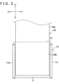
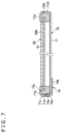
- FIGS. 5 through 7 are views illustrating a mechanism for guiding the display unit 10 along directions of relative movement. These figures illustrate a first guide 61 provided on the mount 20 and a second guide 70 provided on the display unit 10.
- FIG. 5 is a plan view
- FIG. 6 a side elevational view
- FIG. 7 a cross-sectional view taken along line VII - VII of FIG. 6 .
- the mount 20 has a plate-like frame 60.
- the frame 60 has a fixture 60a fixed in the front support 23.
- the first guide 61 is provided on the frame 60.
- the frame 60 has a support 60b extending forwardly from the fixture 60a.
- the first guide 61 is mounted on the support 60b.
- the first guide 61 and the support 60b are disposed on an upper portion of the housing 14 of the display unit 10.
- the display unit 10 has the second guide 70 on the upper portion of the housing 14.
- the second guide 70 guides the first guide 61 for movement along the anterior-posterior directions.
- the second guide 70 has a base 71.
- the base 71 is of a plate-like shape.
- the first guide 61 is disposed above the base 71, for example.
- the first guide 61 may be disposed below the base 71.
- the base 71 has side guides 71R and 71L on its right and left sides.
- the first guide 61 is disposed between the two side guides 71R and 71L.
- the right side guide 71R and the left side guide 71L are positioned respectively on the right and left sides of the first guide 61, and extend along the edges of the first guide 61.
- the side guides 71R and 71L and the base 71 are integrally formed of a metal, for example.
- the guide rail 73L has a portion 73b (see FIG. 7 ) capable of bearing a force directed toward the edge of the first guide 61 from an outer side (specifically, a left side) of the guide rail 73L in the horizontal directions (the portion will hereinafter be referred to as "pressed portion 73b").
- the guide rail 73L has the pressed portion 73b disposed midway along its longitudinal directions.
- the guide rail 73L should have a plurality of pressed portions 73b spaced from each other along its longitudinal directions.
- the side guides 71R and 71L are of a wall-like shape, and are disposed along the guide rails 73R and 73L.
- the side guide 71L has a hole 71a defined therein through which a portion of the side surface of the guide rail 73L is exposed.
- the guide rail 73L can be pressed toward the edge of the first guide 61 through the hole 71a in the side guide 71L.
- a portion of the side surface of the guide rail 73L which corresponds to the hole 71a serves as the pressed portion 73b.
- the side guide 71L may have a plurality of holes 71a spaced from each other along the longitudinal directions of the guide rail 73L.
- the base 71 and the guide rail 73L are arranged so that the position of the guide rail 73L can be slightly moved along the horizontal directions before a fixed member 74 to be described later is fixed to the second guide 70.
- the position of the guide rail 73L along the horizontal directions is secured by a separate member from the base 71 and the guide rail 73L.
- the member which secures the position of the guide rail 73L should preferably have a portion held in contact with the pressed portion 73b.
- the position of the guide rail 73L along the horizontal directions is secured while the guide rail 73L is held in contact with the edge of the first guide 61.
- the "separate member" referred to above includes a structure (e.g., a screw or a fixed member to be described later) or a material (e.g., an adhesive) which can be moved separately from the base 71 and the guide rail 73L before it is used to secure the guide rail 73L.
- a structure e.g., a screw or a fixed member to be described later
- a material e.g., an adhesive
- the fixed portion 74b is of a plate-like shape, for example.
- the pressing portions 74a project upwardly or downwardly from the edge of the fixed portion 74b.
- the fixed member 74 has the plural pressing portions 74a spaced from each other along the lengthwise directions of the guide rail 73L.
- the fixed portion 74b is disposed on the lower surface of the base 71 and fixed to the base 71.
- the fixed portion 74b is welded to the base 71, for example.
- the fixed portion 74b may be fused or bonded to the base 71.
- the guide rail 73L may be fixed to the base 71 by an adhesive rather than the plate-like fixed member 74.
- an adhesive may be introduced through the holes 71a to fill the space between the guide rail 73L and the side guide 71L.
- the adhesive which is solidified functions as a fixed member.
- the base 71 and the guide rail 73L are arranged so that the position of the guide rail 73L can be slightly moved along the horizontal directions.
- the base 71 has holes defined therein and the guide rail 73L has protrusions fitted in the holes.
- the size of the holes along the horizontal directions is slightly larger than the size of the protrusions of the guide rail 73L.
- the side guide 71L has a retaining wall 71b.
- the guide rail 73L is vertically sandwiched by the base 71 and the retaining wall 71b. Consequently, before the position of the guide rail 73L is secured by the fixed member 74, the guide rail 73L is retained by the base 71 while being slightly movable.
- the side guide 71R is of the same structure as the side guide 71L except that the side guide 71L has the holes 71a defined therein.
- the side guide 71R may also have holes 71a defined therein.
- the second guide 70 which has the guide rails 73L and 73R and the fixed member 74 is provided on the display unit 10
- the first guide 61 is provided on the mount 20.
- the second guide 70 which has the guide rails 73L and 73R and the fixed member 74 may be provided on the mount 20, and the first guide 61 may be provided on the display unit 10.
- the locking member 24 may be mounted on the frame 60.
- the locking member 24 and a lower portion (the support 60b described above) of the frame 60 are coupled to the display unit 10.
- the locking member 24 and the lower portion of the frame 60 are guided for movement relative to the display unit 10 by the second guide 70 described above which is provided on the display unit 10.
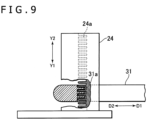
- the display unit 10 in the example illustrated in FIG. 8 has the locked member 31 on an upper portion thereof.
- the locking member 24 has an engaging portion 24a on a lower side thereof.
- the engaging portion 24a includes a plurality of combtooth-shaped convexities arrayed along the anterior-posterior directions (Y1 - Y2 directions).
- the locked member 31 is disposed on a lower side of the locking member 24 and has an engaged portion 31a formed on an upper side thereof.
- the engaged portion 31a also includes a plurality of convexities which engage the plural convexities composing of the engaging portion 24a.
- the locked member 31 is movable between a locked position and an unlocked position.
- the position adjusting mechanism M2 is able to switch between a state wherein the position of the display unit 10 with respect to the front support 23 can be adjusted and a state wherein the position of the displayed unit 10 with respect to the front support 23 is prevented from being adjusted in response to the operation of the lock canceling member 33 by the user.
- a light shielding member may be mounted on the display unit 10.
- the light shielding member should preferably be made of a flexible material.
- the light shielding member is made of an elastomer.
- the display unit 10 has side guards 41 extending rearwardly from the sides of the display unit 10 as an example of the light shielding member.
- the side guards 41 block light on the right and left sides of the HMD 1 when the HMD 1 is in use.
- the frame 13 of the display unit 10 has openings 13a defined in the right and left sides of a rear surface thereof.
- the lenses 12 and the display device 11 are disposed on the inside of the openings 13a.
- the user can see images displayed on the display device 11 through the openings 13a.
- a recess 13b which is open rearwardly and downwardly is defined between the left and right openings 13a.
- a light shielding member 42 may also be disposed in the recess 13b.
- the light shielding member 42 is disposed so as to cover the inside of the recess 13b when the display unit 10 is viewed from behind.
- the light shielding member 42 prevents ambient light from reaching the eyes of the user through the gap between the inner surface of the recess 13b and the nose of the user when the HMD1 is in use.
- the light shielding member 42 is of a sheet-like shape covering (closing) the recess 13b.
- the sheet-like light shielding member 42 is formed of a flexible material, for example.
- the light shielding member 42 may be integrally formed with the side guards 41.
- the light shielding member 42 may be a member separate from the side guards 41, which is mounted on the frame 13 of the display unit 10. In this case, the light shielding member 42 may be detachably mounted on the frame 13.
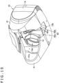
- FIG. 10 is a view illustrating a modification of the light shielding member.
- the display unit 10 has the side guards 41 and the light shielding member 42.
- the side guards 41 have curved edges 41a.
- the curved edges 41a reduce the discomfort which is caused by the edges 41a of the side guards 41 that are pressed against the face of the user when the HMD 1 is mounted on the head.
- the light shielding member 42 has a right side portion 42a and a left side portion 42b opposite the slit 42c.
- the right side portion 42a and the left side portion 42b should preferably have curved edges 42d.
- the curved edges 42d reduce the discomfort which is caused by the edges 42d of the light shielding member 42 that are pressed against the nose of the user when the HMD 1 is mounted on the head.
- the mount 20 may have a front pad on its front side for contacting the front side of the head of the user.
- the front pad should preferably have a cushion.
- the front pad is provided on the rear side of the upper portion 23c of the front support 23.
- the front pad should preferably be supported in a manner to make the angle of the front pad in the anterior-posterior directions adjustable.
- the front pad thus arranged makes it possible to vary the angle of the front pad depending on the shape and size of the head of the user.
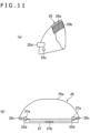
- FIG. 11 is a set of views illustrating an example of a structure which is capable of adjusting the angle of a front pad 25.
- FIG. 11(a) is a side elevational view, partly cut away, of the front pad 25.
- FIG. 11(b) is a plan view of the front pad 25.
- the front pad 25 has a bracket 25a.
- the bracket 25a is formed of a material that is of relatively high rigidity, such as plastics or metal. According to an example of the front pad 25, the bracket 25a is of a plate-like shape.
- a cushion 25b referred to above is attached to the bracket 25a.
- the bracket 25a has shafts 25c on its right and left sides. The shafts 25c are supported in the front support 23, for example. The shafts 25c are positioned on a lower portion of the front pad 25 as viewed in side elevation. An upper portion of the front pad 25 can move about the shafts 25c in the anterior-posterior directions, thereby making it possible to adjust the angle of the front pad 25.
- the mount 20 has an operating member 27 for the user to move the front pad 25.
- the operating member 27 is housed in the front support 23.
- the operating member 27 is supported for sliding movement along the horizontal directions.
- the bracket 25a has pressed portions 25d projecting forwardly.
- the operating member 27 has pressing surfaces 27a for pressing the pressed portions 25d.
- the pressing surfaces 27a are inclined to vary the position of the pressed portions 25d of the bracket 25a in the anterior-posterior directions depending on the position of the operating member 27 in the horizontal directions.
- the operating member 27 has an operating portion 27b exposed on the outer surface of the front support 23.
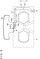
- the HMD 1 in the example described herein has a plurality of light emitters 51 which include light-emitting elements such as LEDs or the like. As described later, when the HMD 1 is in use, an information processing apparatus to which the HMD 1 is connected detects the positions of the plural light emitters 51 through a camera, for thereby detecting the orientation of the head of the user and controlling images displayed on the display device 11 and objects displayed on the display device 11 depending on the orientation of the head. According to an example of the HMD 1, as illustrated in FIGS. 1 and 2 , the plural light emitters 51 are disposed in spaced apart relation to each other on the display unit 10 (in FIGS. 1 and 2 , the light emitters 51 are illustrated hatched for clarification).
- the plural light emitters 51 are disposed in outer peripheral regions of the front surface of the display unit 10. Since the spacing between the light emitters 51 thus arranged is large, the accuracy with which to detect the orientation of the head is increased.
- four light emitters 51 are disposed on the four corners of the front surface of the display unit 10. More specifically, in the example illustrated in FIGS. 1 and 2 , the light emitters 51 are disposed on the four corners of the front surface so that the light emitters 51 extend over both the front and side surfaces of the display unit 10. Stated otherwise, the light emitters 51 are disposed obliquely to the front surface of the display unit 10 so as to face the outer sides of the outer edges of the front surface of the display unit 10.
- the layout of the light emitters 51 is not limited to those described above, but may be modified appropriately.
- the display unit 10 may have only two light emitters 51 spaced from each other in the horizontal directions.
- the display unit 10 may have only two light emitters 51 spaced from each other in the vertical directions.
- the light emitters 51 may not necessarily be provided on the rear support 22a.
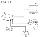
- FIG. 12 is a view illustrating an example of the manner in which the HMD 1 is used.
- a camera 91 is connected to an information processing apparatus 90.
- the information processing apparatus 90 detects the positions of the plural light emitters 51 through the camera 91, and detects the orientation of the head of the user on the basis of the positions of the plural light emitters 51.
- the information processing apparatus 90 generates or corrects a moving-image signal depending on the orientation of the user, and outputs the moving-image signal to the HMD 1.
- the information processing apparatus 90 may output a moving-image signal to a display device 92 such as a television or the like in addition to the HMD 1.
- the moving-image signal output to the HMD 1 and the moving-image signal output to the display device 92 may be different from each other.
- the information processing apparatus 90 may output a moving-image signal for a two-dimensional image to the display device 92, and may output a moving-image signal for a three-dimensional image to the display device 11 of the HMD 1.
- the moving-image signals of those two types may be generated by a dedicated apparatus which is different from the information processing apparatus 90.
- the display unit 10 of the HMD 1 may be provided with sensors such as an acceleration sensor, a gyro sensor, etc.
- the information processing apparatus 90 may generate moving-image signals on the basis of the outputs from the sensors.
- the information processing apparatus 90 may generate moving-image signals on the basis of a signal from an operating device 93 which is manually operated by the user.
- the HMD 1 has the first fastening band 21 and the second fastening band 22 which extend from the front side toward rear side of the HMD 1 for being fastened to the head of the user. At least a portion of the first fastening band 21 is made of an elastically expandable material.
- the second fastening band 22 is made of a material which is less expandable than the above material of the first fastening band 21 and includes the mechanism M1 for adjusting its length.
- the display unit 10 includes the display device 11 and is supported by the first fastening band 21 and the second fastening band 22.
- the user when the user is to mount the HMD 1 on its head, the user initially tentatively secures the position and attitude of the HMD 1 using the first fastening band 21, and then can adjust the length of the second fastening band 22 while the HMD 1 is being tentatively secured. Therefore, when the user adjusts the length of the second fastening band 22, the position and attitude of the HMD 1 is prevented from being varied, allowing the user to adjust the length of the second fastening band 22 easily. Furthermore, as the second fastening band 22 is made of a material less expandable than the first fastening band 21, the second fastening band 22 is mounted on the head of the user with increased stability.
- the present invention is not limited to the HMD 1 described above, but can be modified in various ways.
- first fastening band 21 and the second fastening band 22 may extend rearwardly from the display unit 10 rather than the front support 23.
- one of the first fastening band 21 and the second fastening band 22 may extend rearwardly from the display unit 10, whereas the other band may extend rearwardly from the front support 23.
- One of the first fastening band 21 and the second fastening band 22 may extend rearwardly and upwardly obliquely from the front side of the HMD 1.
- One of the first fastening band 21 and the second fastening band 22 may extend rearwardly horizontally from the front side of the HMD 1.
Landscapes
- Physics & Mathematics (AREA)
- General Physics & Mathematics (AREA)
- Optics & Photonics (AREA)
- Engineering & Computer Science (AREA)
- Computer Hardware Design (AREA)
- Theoretical Computer Science (AREA)
Applications Claiming Priority (2)
| Application Number | Priority Date | Filing Date | Title |
|---|---|---|---|
| JP2014052711 | 2014-03-14 | ||
| PCT/JP2015/055920 WO2015137165A1 (ja) | 2014-03-14 | 2015-02-27 | ヘッドマウントディスプレイ |
Publications (3)
| Publication Number | Publication Date |
|---|---|
| EP3119082A1 EP3119082A1 (en) | 2017-01-18 |
| EP3119082A4 EP3119082A4 (en) | 2017-11-22 |
| EP3119082B1 true EP3119082B1 (en) | 2025-03-26 |
Family
ID=54071613
Family Applications (1)
| Application Number | Title | Priority Date | Filing Date |
|---|---|---|---|
| EP15761982.6A Active EP3119082B1 (en) | 2014-03-14 | 2015-02-27 | Head-mounted display |
Country Status (5)
| Country | Link |
|---|---|
| US (1) | US9703103B2 (zh) |
| EP (1) | EP3119082B1 (zh) |
| JP (1) | JP6253763B2 (zh) |
| CN (2) | CN106105183B (zh) |
| WO (1) | WO2015137165A1 (zh) |
Families Citing this family (81)
| Publication number | Priority date | Publication date | Assignee | Title |
|---|---|---|---|---|
| US9753288B2 (en) * | 2014-01-21 | 2017-09-05 | Osterhout Group, Inc. | See-through computer display systems |
| CN107251547B (zh) | 2015-02-27 | 2020-11-03 | 索尼互动娱乐股份有限公司 | 头戴式显示器 |
| CN104793452B (zh) * | 2015-04-29 | 2016-08-17 | 北京小鸟看看科技有限公司 | 一种微型投影设备 |
| CN105404004A (zh) * | 2015-11-23 | 2016-03-16 | 厦门灵境信息科技有限公司 | 一种头戴式显示设备 |
| JP1561099S (zh) * | 2016-04-27 | 2016-10-17 | ||
| JP1561098S (zh) * | 2016-04-27 | 2016-10-17 | ||
| JP1561101S (zh) * | 2016-04-27 | 2016-10-17 | ||
| JP1561100S (zh) * | 2016-04-27 | 2016-10-17 | ||
| CN106054391B (zh) * | 2016-08-01 | 2019-02-15 | 上海乐蜗信息科技有限公司 | 一种可伸缩头带的虚拟现实眼镜 |
| US10656731B2 (en) | 2016-09-15 | 2020-05-19 | Daqri, Llc | Peripheral device for head-mounted display |
| US10663729B2 (en) * | 2016-09-15 | 2020-05-26 | Daqri, Llc | Peripheral device for head-mounted display |
| CN109791346B (zh) | 2016-09-27 | 2021-04-20 | 斯纳普公司 | 眼镜装置模式指示 |
| DE202017105948U1 (de) * | 2016-10-03 | 2018-03-07 | Google LLC (n.d.Ges.d. Staates Delaware) | Augmented-Reality- und/oder Virtual-Reality-Headset |
| KR102738161B1 (ko) * | 2016-10-18 | 2024-12-05 | 엘지전자 주식회사 | 헤드마운티드 디스플레이 |
| EA035657B1 (ru) * | 2016-12-07 | 2020-07-22 | Бернд Вёрманн | Аппаратура для защиты глаз от излучения |
| TWI626468B (zh) * | 2017-01-25 | 2018-06-11 | 研能科技股份有限公司 | 頭戴式虛擬實境顯示裝置 |
| US11219366B2 (en) * | 2017-02-01 | 2022-01-11 | Rooteehealth, Inc. | Retina photographing apparatus and retina photographing method using same |
| CN206863338U (zh) * | 2017-02-24 | 2018-01-09 | 深圳市大疆创新科技有限公司 | 视频眼镜头带及视频眼镜 |
| CN107065186A (zh) * | 2017-03-31 | 2017-08-18 | 张航铭 | 一种头戴式vr眼镜装置 |
| US10848751B2 (en) * | 2017-05-19 | 2020-11-24 | Facebook Technologies, Llc | Interpupillary distance adjustment in a head-mounted display |
| US11619821B2 (en) | 2017-05-31 | 2023-04-04 | Sony Interactive Entertainment Inc. | Head-mounted display |
| KR102482756B1 (ko) * | 2017-06-14 | 2022-12-30 | 삼성전자주식회사 | 헤드 마운트 디스플레이 장치 |
| CN107588170B (zh) * | 2017-09-08 | 2021-05-18 | 联想(北京)有限公司 | 一种电子设备及其距离调节机构 |
| CN111149354B (zh) | 2017-09-22 | 2022-03-29 | 索尼互动娱乐股份有限公司 | 头戴式显示器 |
| JP2019062345A (ja) | 2017-09-26 | 2019-04-18 | 株式会社ソニー・インタラクティブエンタテインメント | ヘッドマウント装置 |
| JP7200637B2 (ja) | 2017-12-25 | 2023-01-10 | 株式会社リコー | 頭部装着型表示装置および表示システム |
| WO2019131689A1 (en) | 2017-12-25 | 2019-07-04 | Ricoh Company, Ltd. | Head-mounted display device and display system |
| KR102592264B1 (ko) | 2018-02-02 | 2023-10-20 | 삼성전자주식회사 | Hmd 장치 및 그 동작 방법 |
| JP1628837S (zh) * | 2018-02-23 | 2019-04-08 | ||
| JP1628843S (zh) * | 2018-02-23 | 2019-04-08 | ||
| JP1628838S (zh) * | 2018-02-23 | 2019-04-08 | ||
| JP1628842S (zh) * | 2018-02-23 | 2019-04-08 | ||
| JP1628840S (zh) * | 2018-02-23 | 2019-04-08 | ||
| JP1628839S (zh) * | 2018-02-23 | 2019-04-08 | ||
| KR102602848B1 (ko) * | 2018-03-23 | 2023-11-16 | 엘지전자 주식회사 | 헤드 마운티드 디스플레이 |
| US11006043B1 (en) | 2018-04-03 | 2021-05-11 | Snap Inc. | Image-capture control |
| US10905186B2 (en) * | 2018-05-03 | 2021-02-02 | Htc Corporation | Head-mounted display device |
| CN119024566A (zh) * | 2018-05-15 | 2024-11-26 | 索尼公司 | 显示装置 |
| JP7248028B2 (ja) * | 2018-07-24 | 2023-03-29 | ソニーグループ株式会社 | ヘッドマウントディスプレイ |
| US11181748B1 (en) | 2018-09-26 | 2021-11-23 | Apple Inc. | Head support for head-mounted display |
| JP7533858B2 (ja) | 2018-10-15 | 2024-08-14 | 国立大学法人東京農工大学 | ヘッドマウントディスプレイおよびこれに用いられる広焦点レンズの設計方法 |
| CN109239927A (zh) * | 2018-11-15 | 2019-01-18 | 潍坊歌尔电子有限公司 | 头带调节机构及头戴显示设备 |
| US11347303B2 (en) * | 2018-11-30 | 2022-05-31 | Sony Interactive Entertainment Inc. | Systems and methods for determining movement of a controller with respect to an HMD |
| EP3893042A4 (en) | 2018-12-06 | 2022-01-26 | Sony Group Corporation | DRIVE MECHANISM AND HEAD MOUNTED DISPLAY |
| CN109407324B (zh) * | 2018-12-21 | 2025-02-11 | 歌尔科技有限公司 | 绑带调节机构及头戴式智能设备 |
| US12117618B2 (en) | 2019-03-19 | 2024-10-15 | Sony Interactive Entertainment Inc. | Head-mounted display |
| TWI765197B (zh) * | 2019-03-29 | 2022-05-21 | 宏達國際電子股份有限公司 | 頭戴裝置及其束帶結構 |
| US11163333B2 (en) | 2019-03-29 | 2021-11-02 | Htc Corporation | Head-mounted display |
| US11366323B2 (en) | 2019-05-02 | 2022-06-21 | Lg Electronics Inc. | Electronic device for VA, AR, and MR |
| CN111965816B (zh) * | 2019-05-20 | 2022-05-03 | 宏达国际电子股份有限公司 | 头戴式显示器 |
| KR102808965B1 (ko) | 2019-08-09 | 2025-05-20 | 엘지전자 주식회사 | 전자 디바이스 |
| US10712791B1 (en) * | 2019-09-13 | 2020-07-14 | Microsoft Technology Licensing, Llc | Photovoltaic powered thermal management for wearable electronic devices |
| JP7392433B2 (ja) | 2019-11-29 | 2023-12-06 | 株式会社リコー | 頭部装着型表示装置 |
| CN110908121B (zh) * | 2019-12-06 | 2022-08-02 | Oppo广东移动通信有限公司 | 头戴式设备 |
| CN110824715B (zh) * | 2019-12-06 | 2022-01-18 | Oppo广东移动通信有限公司 | 头戴式设备 |
| CN110908120B (zh) * | 2019-12-06 | 2021-11-09 | Oppo广东移动通信有限公司 | 头戴式设备 |
| CN110989170B (zh) * | 2019-12-06 | 2022-06-07 | Oppo广东移动通信有限公司 | 头戴式设备 |
| US12256057B2 (en) * | 2019-12-31 | 2025-03-18 | ResMed Asia Pte. Ltd. | Positioning, stabilising, and interfacing structures and system incorporating same |
| US11262589B2 (en) * | 2020-03-27 | 2022-03-01 | ResMed Pty Ltd | Positioning and stabilising structure and system incorporating same |
| US12461371B2 (en) | 2020-01-23 | 2025-11-04 | National University Corporation Tokyo University Of Agriculture And Technology | Head-mounted display and virtual image forming lens to be used for the head-mounted display |
| US12178276B2 (en) | 2020-03-27 | 2024-12-31 | ResMed Pty Ltd | Positioning and stabilising structure and system incorporating same |
| US11686948B2 (en) | 2020-03-27 | 2023-06-27 | ResMed Pty Ltd | Positioning, stabilising, and interfacing structures and system incorporating same |
| US11598967B2 (en) * | 2020-03-27 | 2023-03-07 | ResMed Pty Ltd | Positioning and stabilising structure and system incorporating same |
| US11846390B2 (en) * | 2020-06-04 | 2023-12-19 | Meta Platforms Technologies, Llc | Pass-through ratcheting mechanism |
| US12399372B1 (en) | 2020-06-12 | 2025-08-26 | Apple Inc. | Support band for wearable electronic device |
| US20230244084A1 (en) * | 2020-07-21 | 2023-08-03 | Sony Group Corporation | Head-mounted device |
| KR102614739B1 (ko) * | 2020-09-14 | 2023-12-15 | 주식회사 메가젠임플란트 | 헤드 마운트 디스플레이장치 |
| US12019248B1 (en) | 2020-09-15 | 2024-06-25 | Apple Inc. | Adjustable head securement for head-mountable device |
| CN111929901B (zh) * | 2020-09-22 | 2021-01-26 | 歌尔光学科技有限公司 | 一种双层绑带式头戴设备 |
| US11726523B1 (en) | 2020-09-25 | 2023-08-15 | Apple Inc. | Head-mountable device with variable stiffness head securement |
| KR102619431B1 (ko) * | 2021-07-01 | 2024-01-02 | 주식회사 피앤씨솔루션 | 초정밀 모터와 거리 측정 센서를 이용해 자동으로 사이즈가 조절되는 머리 착용형 디스플레이 장치 |
| KR102576239B1 (ko) * | 2021-07-01 | 2023-09-08 | 가온그룹 주식회사 | 헤드마운트형 ar 글래스 장치 |
| CN117957832A (zh) | 2021-11-08 | 2024-04-30 | 索尼互动娱乐股份有限公司 | 头戴式显示器 |
| JP7734059B2 (ja) * | 2021-11-29 | 2025-09-04 | 株式会社ソニー・インタラクティブエンタテインメント | 遮光部材、ヘッドマウントディスプレイ |
| TWM630629U (zh) * | 2022-01-24 | 2022-08-11 | 模里西斯商鴻建裕醫療投資股份有限公司 | 擴增實境頭戴式顯示裝置 |
| US20250181164A1 (en) | 2022-03-10 | 2025-06-05 | Sony Interactive Entertainment Inc. | Display control system, display control method, and program |
| US11762208B1 (en) * | 2022-03-31 | 2023-09-19 | Lenovo Global Technology (United States) Inc. | Cooling a virtual reality headset |
| AU2023298332A1 (en) * | 2022-06-28 | 2025-02-13 | Niantic Spatial, Inc. | Compact head-mounted augmented reality system |
| US12449841B2 (en) | 2022-07-21 | 2025-10-21 | Apple Inc. | Devices with detachable headbands |
| JP7759949B2 (ja) * | 2022-08-19 | 2025-10-24 | グーグル エルエルシー | ウェアラブルコンピューティングデバイス及び頭部装着型ウェアラブルコンピューティングデバイス |
| CN117369137A (zh) * | 2023-10-25 | 2024-01-09 | 维沃移动通信有限公司 | 头戴设备 |
Family Cites Families (11)
| Publication number | Priority date | Publication date | Assignee | Title |
|---|---|---|---|---|
| JP3042353B2 (ja) * | 1995-03-22 | 2000-05-15 | 三菱電機株式会社 | ヘッドマウントディスプレイ |
| JPH09304724A (ja) | 1996-05-15 | 1997-11-28 | Sony Corp | 光学視覚装置 |
| JPH1175142A (ja) | 1997-08-29 | 1999-03-16 | Shimadzu Corp | ヘッドマウンテッドディスプレイ装置 |
| US6115846A (en) * | 1998-11-30 | 2000-09-12 | Truesdale; Max T | Headgear combined with a fan, electronic communication device and binoculars |
| US6392798B1 (en) * | 2000-03-22 | 2002-05-21 | Hevec, L.L.C. | Apparatus for holding viewing devices at eye level |
| JP2002247482A (ja) * | 2001-02-16 | 2002-08-30 | Mixed Reality Systems Laboratory Inc | 頭部装着機構及び頭部装着装置 |
| JP3576985B2 (ja) * | 2001-02-28 | 2004-10-13 | キヤノン株式会社 | 位置調整機構及びヘッドマウントディスプレイ装置 |
| US6931668B2 (en) * | 2001-12-21 | 2005-08-23 | Itt Manufacturing Enterprises, Inc. | Headmount apparatus for attaching and supporting devices |
| US6785046B2 (en) * | 2002-06-12 | 2004-08-31 | Darrel D. Newkirk | Zoom monocular and viewing screen |
| SE525238C2 (sv) * | 2002-11-29 | 2005-01-11 | Saab Ab | Anordning anpassad att bäras på en användares huvud, samt huvudburen display med sådan anordning |
| JP2012186660A (ja) | 2011-03-06 | 2012-09-27 | Sony Corp | ヘッド・マウント・ディスプレイ |
-
2015
- 2015-02-27 CN CN201580012555.0A patent/CN106105183B/zh active Active
- 2015-02-27 CN CN201910342808.0A patent/CN109917552B/zh active Active
- 2015-02-27 US US15/123,739 patent/US9703103B2/en active Active
- 2015-02-27 JP JP2016507452A patent/JP6253763B2/ja active Active
- 2015-02-27 EP EP15761982.6A patent/EP3119082B1/en active Active
- 2015-02-27 WO PCT/JP2015/055920 patent/WO2015137165A1/ja not_active Ceased
Also Published As
| Publication number | Publication date |
|---|---|
| JPWO2015137165A1 (ja) | 2017-04-06 |
| JP6253763B2 (ja) | 2017-12-27 |
| CN106105183A (zh) | 2016-11-09 |
| US20170017085A1 (en) | 2017-01-19 |
| CN106105183B (zh) | 2019-05-21 |
| EP3119082A4 (en) | 2017-11-22 |
| CN109917552B (zh) | 2022-09-20 |
| EP3119082A1 (en) | 2017-01-18 |
| US9703103B2 (en) | 2017-07-11 |
| WO2015137165A1 (ja) | 2015-09-17 |
| CN109917552A (zh) | 2019-06-21 |
Similar Documents
| Publication | Publication Date | Title |
|---|---|---|
| EP3119082B1 (en) | Head-mounted display | |
| US12144133B2 (en) | Head-mounted display | |
| US7480133B2 (en) | Head mounted apparatus | |
| ES2926524T3 (es) | Mejoras en o relacionadas con los sistemas de visualización de imágenes | |
| US20210132398A1 (en) | Head-mounted display | |
| JP6833051B2 (ja) | ヘッドマウントディスプレイ | |
| JPWO2019017187A1 (ja) | ヘッドマウントディスプレイ | |
| US20220244549A1 (en) | Attachment and head-mounted display | |
| JP2002247482A (ja) | 頭部装着機構及び頭部装着装置 | |
| JP6428808B2 (ja) | ヘッドマウントディスプレイ | |
| JP2021125706A (ja) | 画像表示装置 | |
| CN115903238B (zh) | 头显机构及头戴式设备 | |
| US20250370270A1 (en) | Video display apparatus with plurality of attachment positions | |
| JP3121579U (ja) | 頭部装着型表示装置 | |
| KR20220003010U (ko) | 헤드마운트 디스플레이 장착장치 | |
| KR20150012371A (ko) | 착용가능한 영상표시장치 |
Legal Events
| Date | Code | Title | Description |
|---|---|---|---|
| PUAI | Public reference made under article 153(3) epc to a published international application that has entered the european phase |
Free format text: ORIGINAL CODE: 0009012 |
|
| STAA | Information on the status of an ep patent application or granted ep patent |
Free format text: STATUS: REQUEST FOR EXAMINATION WAS MADE |
|
| 17P | Request for examination filed |
Effective date: 20160910 |
|
| AK | Designated contracting states |
Kind code of ref document: A1 Designated state(s): AL AT BE BG CH CY CZ DE DK EE ES FI FR GB GR HR HU IE IS IT LI LT LU LV MC MK MT NL NO PL PT RO RS SE SI SK SM TR |
|
| AX | Request for extension of the european patent |
Extension state: BA ME |
|
| DAX | Request for extension of the european patent (deleted) | ||
| RAP1 | Party data changed (applicant data changed or rights of an application transferred) |
Owner name: SONY INTERACTIVE ENTERTAINMENT INC. |
|
| A4 | Supplementary search report drawn up and despatched |
Effective date: 20171024 |
|
| RIC1 | Information provided on ipc code assigned before grant |
Ipc: G02B 27/01 20060101ALI20171018BHEP Ipc: H04N 5/64 20060101AFI20171018BHEP Ipc: G09G 5/00 20060101ALI20171018BHEP |
|
| STAA | Information on the status of an ep patent application or granted ep patent |
Free format text: STATUS: EXAMINATION IS IN PROGRESS |
|
| 17Q | First examination report despatched |
Effective date: 20200730 |
|
| GRAP | Despatch of communication of intention to grant a patent |
Free format text: ORIGINAL CODE: EPIDOSNIGR1 |
|
| STAA | Information on the status of an ep patent application or granted ep patent |
Free format text: STATUS: GRANT OF PATENT IS INTENDED |
|
| INTG | Intention to grant announced |
Effective date: 20241030 |
|
| GRAS | Grant fee paid |
Free format text: ORIGINAL CODE: EPIDOSNIGR3 |
|
| GRAA | (expected) grant |
Free format text: ORIGINAL CODE: 0009210 |
|
| STAA | Information on the status of an ep patent application or granted ep patent |
Free format text: STATUS: THE PATENT HAS BEEN GRANTED |
|
| P01 | Opt-out of the competence of the unified patent court (upc) registered |
Free format text: CASE NUMBER: APP_4478/2025 Effective date: 20250127 |
|
| AK | Designated contracting states |
Kind code of ref document: B1 Designated state(s): AL AT BE BG CH CY CZ DE DK EE ES FI FR GB GR HR HU IE IS IT LI LT LU LV MC MK MT NL NO PL PT RO RS SE SI SK SM TR |
|
| REG | Reference to a national code |
Ref country code: GB Ref legal event code: FG4D |
|
| REG | Reference to a national code |
Ref country code: CH Ref legal event code: EP |
|
| REG | Reference to a national code |
Ref country code: DE Ref legal event code: R096 Ref document number: 602015091291 Country of ref document: DE |
|
| REG | Reference to a national code |
Ref country code: IE Ref legal event code: FG4D |
|
| PG25 | Lapsed in a contracting state [announced via postgrant information from national office to epo] |
Ref country code: RS Free format text: LAPSE BECAUSE OF FAILURE TO SUBMIT A TRANSLATION OF THE DESCRIPTION OR TO PAY THE FEE WITHIN THE PRESCRIBED TIME-LIMIT Effective date: 20250626 |
|
| PG25 | Lapsed in a contracting state [announced via postgrant information from national office to epo] |
Ref country code: FI Free format text: LAPSE BECAUSE OF FAILURE TO SUBMIT A TRANSLATION OF THE DESCRIPTION OR TO PAY THE FEE WITHIN THE PRESCRIBED TIME-LIMIT Effective date: 20250326 |
|
| REG | Reference to a national code |
Ref country code: LT Ref legal event code: MG9D |
|
| PG25 | Lapsed in a contracting state [announced via postgrant information from national office to epo] |
Ref country code: NO Free format text: LAPSE BECAUSE OF FAILURE TO SUBMIT A TRANSLATION OF THE DESCRIPTION OR TO PAY THE FEE WITHIN THE PRESCRIBED TIME-LIMIT Effective date: 20250626 |
|
| PG25 | Lapsed in a contracting state [announced via postgrant information from national office to epo] |
Ref country code: HR Free format text: LAPSE BECAUSE OF FAILURE TO SUBMIT A TRANSLATION OF THE DESCRIPTION OR TO PAY THE FEE WITHIN THE PRESCRIBED TIME-LIMIT Effective date: 20250326 |
|
| PG25 | Lapsed in a contracting state [announced via postgrant information from national office to epo] |
Ref country code: LV Free format text: LAPSE BECAUSE OF FAILURE TO SUBMIT A TRANSLATION OF THE DESCRIPTION OR TO PAY THE FEE WITHIN THE PRESCRIBED TIME-LIMIT Effective date: 20250326 |
|
| PG25 | Lapsed in a contracting state [announced via postgrant information from national office to epo] |
Ref country code: GR Free format text: LAPSE BECAUSE OF FAILURE TO SUBMIT A TRANSLATION OF THE DESCRIPTION OR TO PAY THE FEE WITHIN THE PRESCRIBED TIME-LIMIT Effective date: 20250627 Ref country code: BG Free format text: LAPSE BECAUSE OF FAILURE TO SUBMIT A TRANSLATION OF THE DESCRIPTION OR TO PAY THE FEE WITHIN THE PRESCRIBED TIME-LIMIT Effective date: 20250326 |
|
| REG | Reference to a national code |
Ref country code: NL Ref legal event code: MP Effective date: 20250326 |
|
| PG25 | Lapsed in a contracting state [announced via postgrant information from national office to epo] |
Ref country code: NL Free format text: LAPSE BECAUSE OF FAILURE TO SUBMIT A TRANSLATION OF THE DESCRIPTION OR TO PAY THE FEE WITHIN THE PRESCRIBED TIME-LIMIT Effective date: 20250326 |
|
| PG25 | Lapsed in a contracting state [announced via postgrant information from national office to epo] |
Ref country code: SE Free format text: LAPSE BECAUSE OF FAILURE TO SUBMIT A TRANSLATION OF THE DESCRIPTION OR TO PAY THE FEE WITHIN THE PRESCRIBED TIME-LIMIT Effective date: 20250326 |
|
| REG | Reference to a national code |
Ref country code: AT Ref legal event code: MK05 Ref document number: 1780134 Country of ref document: AT Kind code of ref document: T Effective date: 20250326 |
|
| PG25 | Lapsed in a contracting state [announced via postgrant information from national office to epo] |
Ref country code: SM Free format text: LAPSE BECAUSE OF FAILURE TO SUBMIT A TRANSLATION OF THE DESCRIPTION OR TO PAY THE FEE WITHIN THE PRESCRIBED TIME-LIMIT Effective date: 20250326 |
|
| PG25 | Lapsed in a contracting state [announced via postgrant information from national office to epo] |
Ref country code: ES Free format text: LAPSE BECAUSE OF FAILURE TO SUBMIT A TRANSLATION OF THE DESCRIPTION OR TO PAY THE FEE WITHIN THE PRESCRIBED TIME-LIMIT Effective date: 20250326 Ref country code: PT Free format text: LAPSE BECAUSE OF FAILURE TO SUBMIT A TRANSLATION OF THE DESCRIPTION OR TO PAY THE FEE WITHIN THE PRESCRIBED TIME-LIMIT Effective date: 20250728 |
|
| PG25 | Lapsed in a contracting state [announced via postgrant information from national office to epo] |
Ref country code: PL Free format text: LAPSE BECAUSE OF FAILURE TO SUBMIT A TRANSLATION OF THE DESCRIPTION OR TO PAY THE FEE WITHIN THE PRESCRIBED TIME-LIMIT Effective date: 20250326 Ref country code: IT Free format text: LAPSE BECAUSE OF FAILURE TO SUBMIT A TRANSLATION OF THE DESCRIPTION OR TO PAY THE FEE WITHIN THE PRESCRIBED TIME-LIMIT Effective date: 20250326 |
|
| PG25 | Lapsed in a contracting state [announced via postgrant information from national office to epo] |
Ref country code: AT Free format text: LAPSE BECAUSE OF FAILURE TO SUBMIT A TRANSLATION OF THE DESCRIPTION OR TO PAY THE FEE WITHIN THE PRESCRIBED TIME-LIMIT Effective date: 20250326 |
|
| PG25 | Lapsed in a contracting state [announced via postgrant information from national office to epo] |
Ref country code: EE Free format text: LAPSE BECAUSE OF FAILURE TO SUBMIT A TRANSLATION OF THE DESCRIPTION OR TO PAY THE FEE WITHIN THE PRESCRIBED TIME-LIMIT Effective date: 20250326 |
|
| PG25 | Lapsed in a contracting state [announced via postgrant information from national office to epo] |
Ref country code: RO Free format text: LAPSE BECAUSE OF FAILURE TO SUBMIT A TRANSLATION OF THE DESCRIPTION OR TO PAY THE FEE WITHIN THE PRESCRIBED TIME-LIMIT Effective date: 20250326 |
|
| PG25 | Lapsed in a contracting state [announced via postgrant information from national office to epo] |
Ref country code: SK Free format text: LAPSE BECAUSE OF FAILURE TO SUBMIT A TRANSLATION OF THE DESCRIPTION OR TO PAY THE FEE WITHIN THE PRESCRIBED TIME-LIMIT Effective date: 20250326 |
|
| PG25 | Lapsed in a contracting state [announced via postgrant information from national office to epo] |
Ref country code: IS Free format text: LAPSE BECAUSE OF FAILURE TO SUBMIT A TRANSLATION OF THE DESCRIPTION OR TO PAY THE FEE WITHIN THE PRESCRIBED TIME-LIMIT Effective date: 20250726 |