EP3115532B1 - Bandaufnahme für ein türband und anordnung einer bandaufnahme an einem türband - Google Patents
Bandaufnahme für ein türband und anordnung einer bandaufnahme an einem türband Download PDFInfo
- Publication number
- EP3115532B1 EP3115532B1 EP15176326.5A EP15176326A EP3115532B1 EP 3115532 B1 EP3115532 B1 EP 3115532B1 EP 15176326 A EP15176326 A EP 15176326A EP 3115532 B1 EP3115532 B1 EP 3115532B1
- Authority
- EP
- European Patent Office
- Prior art keywords
- hinge
- receptacle
- front plate
- receptacle body
- receiving body
- Prior art date
- Legal status (The legal status is an assumption and is not a legal conclusion. Google has not performed a legal analysis and makes no representation as to the accuracy of the status listed.)
- Active
Links
Images
Classifications
-
- E—FIXED CONSTRUCTIONS
- E05—LOCKS; KEYS; WINDOW OR DOOR FITTINGS; SAFES
- E05D—HINGES OR SUSPENSION DEVICES FOR DOORS, WINDOWS OR WINGS
- E05D5/00—Construction of single parts, e.g. the parts for attachment
- E05D5/02—Parts for attachment, e.g. flaps
-
- E—FIXED CONSTRUCTIONS
- E05—LOCKS; KEYS; WINDOW OR DOOR FITTINGS; SAFES
- E05Y—INDEXING SCHEME ASSOCIATED WITH SUBCLASSES E05D AND E05F, RELATING TO CONSTRUCTION ELEMENTS, ELECTRIC CONTROL, POWER SUPPLY, POWER SIGNAL OR TRANSMISSION, USER INTERFACES, MOUNTING OR COUPLING, DETAILS, ACCESSORIES, AUXILIARY OPERATIONS NOT OTHERWISE PROVIDED FOR, APPLICATION THEREOF
- E05Y2600/00—Mounting or coupling arrangements for elements provided for in this subclass
- E05Y2600/40—Mounting location; Visibility of the elements
- E05Y2600/45—Mounting location; Visibility of the elements in or on the fixed frame
-
- E—FIXED CONSTRUCTIONS
- E05—LOCKS; KEYS; WINDOW OR DOOR FITTINGS; SAFES
- E05Y—INDEXING SCHEME ASSOCIATED WITH SUBCLASSES E05D AND E05F, RELATING TO CONSTRUCTION ELEMENTS, ELECTRIC CONTROL, POWER SUPPLY, POWER SIGNAL OR TRANSMISSION, USER INTERFACES, MOUNTING OR COUPLING, DETAILS, ACCESSORIES, AUXILIARY OPERATIONS NOT OTHERWISE PROVIDED FOR, APPLICATION THEREOF
- E05Y2600/00—Mounting or coupling arrangements for elements provided for in this subclass
- E05Y2600/50—Mounting methods; Positioning
- E05Y2600/502—Clamping
-
- E—FIXED CONSTRUCTIONS
- E05—LOCKS; KEYS; WINDOW OR DOOR FITTINGS; SAFES
- E05Y—INDEXING SCHEME ASSOCIATED WITH SUBCLASSES E05D AND E05F, RELATING TO CONSTRUCTION ELEMENTS, ELECTRIC CONTROL, POWER SUPPLY, POWER SIGNAL OR TRANSMISSION, USER INTERFACES, MOUNTING OR COUPLING, DETAILS, ACCESSORIES, AUXILIARY OPERATIONS NOT OTHERWISE PROVIDED FOR, APPLICATION THEREOF
- E05Y2900/00—Application of doors, windows, wings or fittings thereof
- E05Y2900/10—Application of doors, windows, wings or fittings thereof for buildings or parts thereof
- E05Y2900/13—Type of wing
- E05Y2900/132—Doors
Definitions
- the present invention relates to a tape holder for a door hinge according to the preamble of claim 1 and an arrangement of such a tape holder on a door hinge.
- the present on the market tape recordings are made entirely of plastic or of a steel or steel sheet, such as the steel bag St53 of the Applicant.
- a steel or steel sheet such as the steel bag St53 of the Applicant.
- Made of plastic tape pockets have the disadvantage that their capacity is very limited, as they deform greatly under load, with the result that the door hinges are not held in the intended position on the door frame.
- Tape holders made of sheet steel with two sleeves attached thereto as a positioning or centering aid are very complicated to produce.
- the commercially available tape recordings of this type have either welded sleeves or pipe sections or are made in one piece by means of rolled pipe sections.
- Tape recordings with rolled pipe sections also have the disadvantage that with large sheet thicknesses of the outer diameter of these pipe sections is very large, resulting in visual disadvantages in the installation situation.
- the production of such tape recordings is complicated, in particular multi-stage.
- Object of the present invention is to provide a tape recording for a door hinge and an arrangement of such a tape recording for a door hinge, with which the above-mentioned disadvantages can be eliminated and in particular is easy to manufacture.
- a tape holder for a door hinge with at least one fastening pin having the features of claim 1 and by an arrangement of a tape recording on a door hinge with the features of claim 13.
- the tape holder according to the invention for a door hinge with at least one fastening pin has a receiving body for receiving the at least one fastening pin, a releasably fixed to the receiving body clamping device for clamping the fastening pin on the receiving body and at least one positioning sleeve for positioning the tape recording on a door frame, through which at least one fastening pin is pushed through.
- the at least one positioning sleeve is arranged on a front plate fixed to the receiving body, wherein at least one surface of the receiving body is made of a different material than a surface of the front plate and the at least one positioning sleeve. For ease of assembly, the front panel and the receiving body are plugged into each other.
- At least one positioning sleeve of the receiving body By separating the at least one positioning sleeve of the receiving body is made possible that at least the surfaces of the receiving body or the front plate and the at least one positioning sleeve can be made separately from each other in a simple manner, so that, for example, the front panel with the attached thereto positioning sleeve with a Coating can be provided, for example, allows an adaptation of the surface in a wide range of colors.
- the receiving body of a different material than the front plate and the at least one positioning sleeve.
- the receptacle body for example, made of steel and the front panel made of plastic and thus allows the production of an extremely stable tape recording together with a diverse color design option for the positioning sleeves of the front panel.
- a projection is formed on one of the front plate facing front edge of the receiving body, which can be inserted into a recess of the front panel, in particular einpressbar.
- elastically deformable bulges are integrally formed in the recess of the front plate, with which a press fit with the approach of the receiving body can be produced, wherein the bulges deform elastically.
- At least one approach is formed on the front plate, which is attachable to the receiving body and thus ensures in a likewise simple manner, an assembly of the two components.
- the approach is designed as a web which can be inserted into a groove of the receiving body.
- the approach consists of several from the receiving body facing surface of the front plate protruding pins which are attachable to one of the front panel facing end edge of the receiving body.
- the approach consists of at least one of the receiving body facing surface of the front plate protruding tab, in which a recess is provided, wherein the recess is attachable to a formed on the receiving body threaded passage.
- This thread passage also serves to receive a clamping screw, which is part of a preferred embodiment of a clamping device is, with a clamping plate on the receiving body, the at least one fastening pin is clamped attractable.
- supporting webs are arranged on the receiving body, with which a plurality of such tape recordings are stacked on each other in a simple manner, wherein a plurality of support points of the stacked tape recordings arise on the one hand by the tabs and on the other hand, for example by juxtaposition of the clamping screws.
- an inlet chamfer is integrally formed on an end edge of the positioning sleeve, with the insertion of the tape recording in the designated hole of the door frame is substantially facilitated.
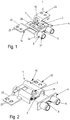
- FIGS. 6 and 7 a first embodiment of a tape recording according to the invention is shown.
- the tape recording serves to receive a door hinge, as in the FIGS. 6 and 7 is shown.
- the door hinge 18 consists essentially of a vertical in the installed situation upright for suspending the door or attached to the door receiving sleeves and perpendicular to the spar on the door hinge extending fastening pins 17 which are received in the tape recording by clamping.
- the tape holder has a receiving body 1 for receiving the two fixing pins 17.
- the fastening pins 17 are received in receiving pockets 28 of the receiving body 1 which are formed in part-cylindrical manner. It is also conceivable, the shape of the receiving body 1 with only one such receiving pocket 28 or with more than two such receiving pockets 28 for receiving a corresponding number of fixing pins 17th
- a clamping device 2 releasably fixed to the receiving body 1 is provided.
- this clamping device 2 is designed as a clamping plate 26 which can be fixed with a clamping screw 3 which can be screwed into a threaded passage 14 which can be screwed onto the receiving body 1, wherein the clamping screw 3 passes through a bore provided on the clamping plate 26.
- the clamping plate 26 is centrally fixed in the receiving body 1 by the clamping screw 3 in the threaded passage 14.
- the fixing pins 17 clamping edges 27 of the clamping plate 26 are adapted to the contour of the mounting pins 17 slightly angled relative to the central part of the clamping plate 26 is formed.
- the receiving body 1 Perpendicular to the longitudinal extent of the receiving pockets 28, the receiving body 1 has respective tabs 22 provided thereon with holes 23 through which in the mounted state on the door frame 20 fitting fastening screws 25 are performed, with which the receiving body 1 is fixed to the door frame 20.
- the end face of the screw head of the clamping screw 3 remote end of the clamping screw 3 is preferably used together with issued from the pockets 28 webs 16 of the simple stackability of the tape holders.
- positioning sleeves 6, which are arranged on a fixed to the receiving body 1 front panel 4, in particular anformt.
- the positioning sleeves 6 are inserted during assembly into holes 19 provided in the door frame 20.
- the receiving body 1 is fixed to the front panel 4 and can in this fixed position by means of screws 25, which pass through the holes 23 of the tabs 22, attached to the door frame 20, insbeosndere be screwed.
- a stable receiving body 1 in which the mounting pins 17 are received by clamping and on the other hand, easy and accurate to make positioning sleeves 6, which are visually appealing, at least the surface of the receiving body 1 made of a different material than the surface of the front panel. 4 and the positioning sleeves 6.
- the receiving body 1 itself consists of a different material, preferably of steel, than the front plate 4 and arranged thereon, in particular molded positioning sleeves 6, which are preferably made of a plastic.
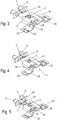
- this compound is designed as a press fit, wherein in the recess 9 of the front plate 4 elastically deformable bulges 8, for example, formed as ribs, are formed, which deform elastically when pressing the lug 5 into the recesses 9.
- At least one projection 7 is formed on the front panel 4, which can be attached to the receiving body 1.
- the approach 7 consists of several of the receiving body 1 facing surface of the front panel 4 protruding pins 12 which are attachable to one of the front panel 4 facing end edge of the receiving body 1.
- each two of the pins 12 is preferably such that they are easily deformed when plugging onto the end edge of the receiving body 1 and so the front panel 4 is clamped to the receiving body 1.
- the projection 7 consists of a one of the receiving body 1 facing surface of the front panel 4 protruding tab 13.
- the tab 13 is provided with a recess 15 which is attachable to the integrally formed on the receiving body 1 threaded passage 14.
- the width of the tab 13 is preferably dimensioned so that their edges extending in the longitudinal direction of the pockets 28 abut the rear sides of the pocket edges 28.
- an inlet chamfer 21 is integrally formed on the front edge of the positioning sleeves 6, which facilitate the insertion of the tape recording in the holes provided 19 of the door frame 20.
- the fixing pins 17 extend through the positioning sleeves 6 into the pockets 28 of the tape holders.
- the visible from the outside ends of the positioning sleeves 6 are preferred by the Production of the positioning sleeves 6 and the front panel 4 made of a plastic to the color of the door frame 20 or any other color customizable einfärbbar.
Landscapes
- Engineering & Computer Science (AREA)
- Mechanical Engineering (AREA)
- Connection Of Plates (AREA)
- Hinges (AREA)
Description
- Die vorliegende Erfindung betrifft eine Bandaufnahme für ein Türband gemäß dem Oberbegriff des Anspruchs 1 sowie eine Anordnung einer solchen Bandaufnahme an einem Türband.
- Solche beispielsweise aus der
DE 202 04 010 U1 bekannten Bandaufnahmen, die an einem Türband befestigt werden, dienen der Aufnahme eines oder mehrerer Befestigungsstifte eines Türbandes, die senkrecht zur Schwenkachse des Türbandes am Türband angeordnet in dazu vorgesehenen Aufnahmetaschen der Bandaufnahmen aufgenommen sind. - Die heute auf dem Markt befindlichen Bandaufnahmen sind dabei vollständig aus Kunststoff oder aus einem Stahl bzw. Stahlblech, wie beispielsweise die Stahltasche St53 der Anmelderin gefertigt. Zur Zentrierung und Positionierhilfe beim Einbau der Bandtaschen in eine Türzarge weisen zahlreiche dieser Bandtaschen zwei Hülsen auf, die in dazu vorgesehenen Bohrungen im Türband einliegen bzw. eingesteckt sind.
- Aus Kunststoff gefertigte Bandtaschen haben dabei den Nachteil, dass ihre Belastbarkeit sehr begrenzt ist, da sich diese bei Belastung stark verformen, was zur Folge hat, dass die Türbänder nicht in der vorgesehenen Position an der Türzarge gehalten werden.
- Bandaufnahmen aus Stahlblech mit zwei daran angesetzten Hülsen als Positionier- oder Zentrierhilfe sind in der Herstellung sehr aufwändig. Die marktüblichen Bandaufnahmen dieser Bauart weisen dabei entweder angeschweißte Hülsen oder Rohrstücken auf oder sind einstückig mittels angerollter Rohrstücke hergestellt.
- Bandaufnahmen mit angerollten Rohrstücken haben des Weiteren den Nachteil, dass bei großen Blechstärken der Außendurchmesser dieser Rohrstücke sehr groß wird, was zu optischen Nachteilen in der Einbausituation führt. Außerdem ist die Herstellung solcher Bandaufnahmen aufwändig, insbesondere mehrstufig.
- Auch die farbliche Gestaltung von Stahlblech-Bandaufnahmen ist sehr stark eingeschränkt. Des Weiteren ist eine genaue kreisförmige Ausführung der Zentrierhülsen oder -rohrstücke schwierig.
- Aufgabe der vorliegenden Erfindung ist es, eine Bandaufnahme für ein Türband sowie eine Anordnung einer solchen Bandaufnahme für ein Türband bereitzustellen, mit der die oben genannten Nachteile beseitigt werden können und die insbesondere einfach herstellbar ist.
- Diese Aufgabe wird durch eine Bandaufnahme für ein Türband mit wenigstens einem Befestigungsstift mit den Merkmalen des Anspruchs 1 sowie durch eine Anordnung einer Bandaufnahme an einem Türband mit den Merkmalen des Anspruchs 13 gelöst.
- Die erfindungsgemäße Bandaufnahme für ein Türband mit wenigstens einem Befestigungsstift weist einen Aufnahmekörper zur Aufnahme des wenigstens einen Befestigungsstiftes auf, eine an dem Aufnahmekörper lösbar festgelegte Klemmvorrichtung zum Festklemmen des Befestigungsstiftes an dem Aufnahmekörper sowie wenigstens eine Positionierhülse zur Positionierung der Bandaufnahme an einer Türzarge, durch die der wenigstens eine Befestigungsstift durchsteckbar ist. Die wenigstens eine Positionierhülse ist an einer an dem Aufnahmekörper festgelegten Frontplatte angeordnet, wobei zumindest eine Oberfläche des Aufnahmekörpers aus einem anderen Material besteht als eine Oberfläche der Frontplatte und der wenigstens einen Positionierhülse. Zur einfachen Montage sind die Frontplatte und der Aufnahmekörper aneinander steckbar ausgebildet.
- Durch die Trennung der wenigstens einen Positionierhülse von dem Aufnahmekörper ist ermöglicht, dass zumindest die Oberflächen des Aufnahmekörpers bzw. der Frontplatte und der wenigstens einen Positionierhülse getrennt voneinander in einfacher Weise gefertigt werden können, so dass beispielsweise auch die Frontplatte mit der daran angebauten Positionierhülse mit einer Beschichtung versehen werden können, die beispielsweise eine Anpassung der Oberfläche in einer breiten farblichen Palette ermöglicht.
- Vorteilhafte Ausführungsvarianten der Erfindung sind Gegenstand der Unteransprüche.
- Gemäß einer vorteilhaften Ausführungsvariante der Erfindung besteht der Aufnahmekörper aus einem anderen Material als die Frontplatte und die wenigstens eine Positionierhülse. So kann der Aufnahmekörper beispielsweise aus Stahl und die Frontplatte aus Kunststoff bestehen und ermöglicht so die Fertigung einer äußerst stabilen Bandaufnahme zusammen mit einer mannigfaltigen Farbgestaltungsmöglichkeit für die Positionierhülsen der Frontplatte.
- Gemäß einer bevorzugten Ausführungsvariante ist an einer der Frontplatte zugewandten Stirnkante des Aufnahmekörpers ein Ansatz angeformt, der in eine Ausnehmung der Frontplatte einsetzbar, insbesondere einpressbar ist. Dadurch ist eine einfach zu montierende Verbindung zwischen dem Aufnahmekörper und der Frontplatte ermöglicht.
- In einer besonderen Ausführung der Erfindung sind in der Ausnehmung der Frontplatte elastisch verformbare Aufwölbungen angeformt, mit denen eine Presspassung mit dem Ansatz des Aufnahmekörpers herstellbar ist, wobei sich die Aufwölbungen elastisch verformen.
- In einer weiteren Ausführungsvariante der Erfindung ist an der Frontplatte wenigstens ein Ansatz angeformt, der an den Aufnahmekörper ansteckbar ist und damit in ebenfalls einfacher Weise eine Montage der beiden Bauteile gewährleistet.
- Besonders bevorzugt ist der Ansatz dabei als Steg ausgebildet, der in eine Nut des Aufnahmekörpers einsteckbar ist. Alternativ besteht der Ansatz aus mehreren aus der dem Aufnahmekörper zugewandten Fläche der Frontplatte vorstehenden Stiften, die auf eine der Frontplatte zugewandte Stirnkante des Aufnahmekörpers aufsteckbar sind.
- Insbesondere bei Fertigung der Frontplatte aus einem Kunststoff sind solche Stifte in einfacher Weise an die Frontplatte anspritzbar.
- Nach einer nochmals alternativen Ausführungsvariante besteht der Ansatz aus wenigstens einer aus der dem Aufnahmekörper zugewandten Fläche der Frontplatte vorstehenden Lasche, in der eine Ausnehmung vorgesehen ist, wobei die Ausnehmung auf einen am Aufnahmekörper angeformten Gewindedurchzug aufsteckbar ist.
- Dieser Gewindedurchzug dient gleichzeitig der Aufnahme einer Klemmschraube, die Bestandteil einer bevorzugten Ausführungsvariante einer Klemmvorrichtung ist, mit der eine Klemmplatte am Aufnahmekörper, den wenigstens einen Befestigungsstift klemmend anziehbar ist.
- Gemäß einer weiteren vorteilhaften Ausführungsvariante der Erfindung sind am Aufnahmekörper Stützstege angeordnet, mit denen mehrere solcher Bandaufnahmen in einfacher weise aufeinander stapelbar sind, wobei mehrere Auflagepunkte der aufeinander liegenden Bandaufnahmen einerseits durch die Laschen und andererseits beispielsweise durch Aufeinanderliegen der Klemmschrauben entstehen.
- Gemäß einer weiteren bevorzugten Ausführungsvariante der Erfindung ist an einer Stirnkante der Positionierhülse eine Einlauffase angeformt, mit der ein Einschieben der Bandaufnahme in die dafür vorgesehene Bohrung der Türzarge wesentlich erleichtert wird.
- Nachfolgend werden Ausführungsbeispiele anhand der beiliegenden Zeichnungen näher erläutert. Es zeigen:
- Figur 1
- eine perspektivische Ansicht einer Ausführungsvariante einer erfindungsgemäßen Bandaufnahme im zusammengesetzten Zustand,
- Figur 2
- eine perspektivische Ansicht der Bandaufnahme aus
Figur 1 aus einer anderen Perspektive vor dem Zusammensetzen des Aufnahmekörpers mit der Frontplatte, - Figuren 3-5
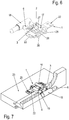
- perspektivische Ansichten zur Darstellung unterschiedlicher Befestigungsvarianten der Frontplatte mit dem Aufnahmekörper,
- Figur 6
- eine perspektivische Ansicht der in
Figur 1 gezeigten Bandaufnahme mit darin klemmend befestigtem Türband und - Figur 7
- eine perspektivische teilaufgerissene Darstellung einer Ausführungsvariante einer erfindungsgemäßen Bandaufnahme mit daran klemmend befestigtem Türband in der Einbausituation an einer Türzarge.
- In der nachfolgenden Figurenbeschreibung beziehen sich Begriffe wie oben, unten, links, rechts, vorne, hinten usw. ausschließlich auf die in den jeweiligen Figuren gewählte beispielhafte Darstellung und Position des Aufnahmekörpers, der Frontplatte, des Befestigungsstiftes, der Positionierhülse, des Ansatzes und dergleichen. Diese Begriffe sind nicht einschränkend zu verstehen, d.h., durch verschiedene Arbeitsstellungen oder die spiegelsymmetrische Auslegung oder dergleichen können sich diese Bezüge ändern.
- In den
Figuren 1 und 2 ist eine erste Ausführungsvariante einer erfindungsgemäßen Bandaufnahme gezeigt. Die Bandaufnahme dient dabei der Aufnahme eines Türbandes, wie es in denFiguren 6 und 7 gezeigt ist. Das Türband 18 besteht im Wesentlichen aus einem in der eingebauten Situation vertikal stehenden Holm zum Einhängen der Tür bzw. an der Tür befestigten Aufnahmehülsen und senkrecht zu dem Holm am Türband sich erstreckenden Befestigungsstiften 17, die in der Bandaufnahme klemmend aufgenommen sind. - Die Bandaufnahme weist einen Aufnahmekörper 1 zur Aufnahme der beiden Befestigungsstifte 17 auf. Die Befestigungsstifte 17 sind dabei in dazu teilzylindrisch geformten Aufnahmetaschen 28 des Aufnahmekörpers 1 aufgenommen. Denkbar ist auch, die Ausformung des Aufnahmekörpers 1 mit lediglich einer solchen Aufnahmetasche 28 oder auch mit mehr als zwei solcher Aufnahmetaschen 28 zur Aufnahme einer entsprechenden Anzahl von Befestigungsstiften 17.
- Zur Fixierung der Befestigungsstifte 17 ist eine an dem Aufnahmekörper 1 lösbar festgelegte Klemmvorrichtung 2 vorgesehen. Diese Klemmvorrichtung 2 ist in der hier gezeigten Ausführungsvariante als mit einer in einem am Aufnahmekörper 1 angeformten Gewindedurchzug 14 anschraubbare Klemmschraube 3 festlegbare Klemmplatte 26 ausgebildet, wobei die Klemmschraube 3 eine an der Klemmplatte 26 vorgesehene Bohrung durchtritt. Die Klemmplatte 26 ist dabei zentral im Aufnahmekörper 1 durch die Klemmschraube 3 im Gewindedurchzug 14 fixiert. Die die Befestigungsstifte 17 klemmenden Ränder 27 der Klemmplatte 26 sind dabei an die Kontur der Befestigungsstifte 17 angepasst leicht abgewinkelt gegenüber dem zentralen Teil der Klemmplatte 26 ausgebildet.
- Senkrecht zur Längserstreckung der Aufnahmetaschen 28 weist der Aufnahmekörper 1 jeweilige Laschen 22 mit daran vorgesehenen Bohrungen 23 auf, durch die im montierten Zustand an der Türzarge 20 anliegend Befestigungsschrauben 25 durchgeführt sind, mit denen der Aufnahmekörper 1 an der Türzarge 20 fixiert ist.
- Die Stirnfläche des vom Schraubenkopf der Klemmschraube 3 entfernten Endes der Klemmschraube 3 dient bevorzugt zusammen mit aus den Taschen 28 ausgestellten Stegen 16 der einfachen Stapelbarkeit der Bandaufnahmen.
- Zur lagerichtigen Fixierung der Bandaufnahme an der Türzarge 20 dienen Positionierhülsen 6, die an einer an dem Aufnahmekörper 1 festgelegten Frontplatte 4 angeordnet, insbesondere anformt sind. Die Positionierhülsen 6 werden bei der Montage in dazu vorgesehene Bohrungen 19 in der Türzarge 20 eingesteckt. Im Anschluss wird der Aufnahmekörper 1 an der Frontplatte 4 fixiert und kann in dieser fixierten Position mithilfe der Schrauben 25, die die Bohrungen 23 der Laschen 22 durchtreten, an der Türzarge 20 befestigt, insbeosndere verschraubt werden.
- Um einerseits einen stabilen Aufnahmekörper 1, in dem die Befestigungsstifte 17 klemmend aufgenommen sind und andererseits einfach und exakt zu fertigende Positionierhülsen 6, die optisch ansprechend sind, zu ermöglichen, bestehen zumindest die Oberfläche des Aufnahmekörpers 1 aus einem anderen Material als die Oberfläche der Frontplatte 4 und der Positionierhülsen 6.
- Insbesondere besteht der Aufnahmekörper 1 selbst aus einem anderen Material, bevorzugt aus Stahl, als die Frontplatte 4 und die daran angeordneten, insbesondere angeformten Positionierhülsen 6, die vorzugsweise aus einem Kunststoff gefertigt sind.
- Zur einfachen Montage des Aufnahmekörpers 1 mit der Frontplatte 4 sind diese, wie in den
Figuren 2-5 gezeigt, aneinander steckbar ausgebildet. - Dazu sind, wie in der in
Figur 2 gezeigten Ausführungsvariante der Bandaufnahme gezeigt, an einer der Frontplatte 4 zugewandten Stirnkante des Aufnahmekörpers 1 ein Ansatz 5 in Gestalt eines sich parallel zur Längserstreckung der Taschen 28 erstreckenden vorstehenden Steges ausgebildet, der in eine Ausnehmung 9 der Frontplatte 4 einsetzbar, insbesondere einpressbar ist. - Besonders bevorzugt ist diese Verbindung als Presspassung ausgebildet, wobei in der Ausnehmung 9 der Frontplatte 4 elastisch verformbar Aufwölbungen 8 , beispielsweise als Rippen geformt, angeformt sind, die sich beim Einpressen des Ansatzes 5 in die Ausnehmungen 9 elastisch verformen.
- Bei den in den
Figuren 3-5 gezeigten Ausführungsvarianten ist an der Frontplatte 4 wenigstens ein Ansatz 7 angeformt, der an den Aufnahmekörper 1 ansteckbar ist. - So ist bei der in
Figur 3 gezeigten Ausführungsvariante der Ansatz 7 als sich in der Ebene der Platte 24 der Frontplatte 4 erstreckender Steg 10 ausgebildet, der in eine Nut 11 des Aufnahmekörpers 1 einsteckbar ist. Die Nut 11 ist dabei an einer der Frontplatte 4 zugewandten Stirnkante des zentralen Bereichs des Aufnahmekörpers 1 angeformt. - Bei der in
Figur 4 gezeigten Ausführungsvariante besteht der Ansatz 7 aus mehreren aus der dem Aufnahmekörper 1 zugewandten Fläche der Frontplatte 4 vorstehenden Stiften 12, die auf eine der Frontplatte 4 zugewandten Stirnkante des Aufnahmekörpers 1 aufsteckbar sind. - Der Abstand zwischen jeweils zweien der Stifte 12 ist dabei vorzugsweise so bemessen, dass diese beim Aufstecken auf die Stirnkante des Aufnahmekörpers 1 leicht verformt werden und so die Frontplatte 4 klemmend an dem Aufnahmekörper 1 gehalten ist.
- Bei der in
Figur 5 gezeigten Ausführungsvariante besteht der Ansatz 7 aus einer aus der dem Aufnahmekörper 1 zugewandten Fläche der Frontplatte 4 vorstehenden Lasche 13. Die Lasche 13 ist dabei mit einer Ausnehmung 15 versehen, die auf den am Aufnahmekörper 1 angeformten Gewindedurchzug 14 aufsteckbar ist. - Die Breite der Lasche 13 ist dabei vorzugsweise so bemessen, dass ihre sich in Längsrichtung der Taschen 28 erstreckenden Ränder an den Rückseiten der Taschenränder 28 anliegen.
- Wie in
Figur 1 des Weiteren gezeigt ist, ist an der Stirnkante der Positionierhülsen 6 eine Einlauffase 21 angeformt, die das Einschieben der Bandaufnahme in die dafür vorgesehenen Bohrungen 19 der Türzarge 20 erleichtern. - Im montierten Zustand, gezeigt in
Figur 7 , erstrecken sich die Befestigungsstifte 17 durch die Positionierhülsen 6 hindurch in die Taschen 28 der Bandaufnahmen. Die von außen sichtbaren Enden der Positionierhülsen 6 sind durch die bevorzugte Fertigung der Positionierhülsen 6 und der Frontplatte 4 aus einem Kunststoff an die Farbe der Türzarge 20 oder eine beliebige andere Farbe anpassbar einfärbbar. -
- 1
- Aufnahmekörper
- 2
- Klemmvorrichtung
- 3
- Klemmschraube
- 4
- Frontplatte
- 5
- Ansatz
- 6
- Positionierhülse
- 7
- Ansatz
- 8
- Ausnehmung
- 9
- Aufwölbung
- 10
- Steg
- 11
- Nut
- 12
- Stift
- 13
- Lasche
- 14
- Mantelfläche
- 15
- Ausnehmung
- 16
- Steg
- 17
- Befestigungsstift
- 18
- Türband
- 19
- Bohrung
- 20
- Türzarge
- 21
- Fase
- 22
- Lasche
- 23
- Bohrung
- 24
- Platte
- 25
- Befestigungsschraube
- 26
- Klemmplatte
- 27
- Rand
- 28
- Aufnahmetasche
Claims (13)
- Bandaufnahme für ein Türband (18) mit wenigstens einem Befestigungsstift (17), aufweisend- einen Aufnahmekörper (1) zur Aufnahme des wenigstens einen Befestigungsstiftes (17),- eine an dem Aufnahmekörper (1) lösbar festgelegte Klemmvorrichtung (2) zum Festklemmen des Befestigungsstiftes (17) an dem Aufnahmekörper (1),- wenigstens eine Positionierhülse (6) zur Positionierung der Bandaufnahme an einer Türzarge (20), durch die der wenigstens eine Befestigungsstift (17) durchsteckbar ist,- wobei die wenigstens eine Positionierhülse (6) an einer an dem Aufnahmekörper (1) festgelegten Frontplatte (4) angeordnet ist,
dadurch gekennzeichnet, dass- zumindest eine Oberfläche des Aufnahmekörpers (1) aus einem anderen Material besteht als eine Oberfläche der Frontplatte (4) und der wenigstens einen Positionierhülse (6),- wobei die Frontplatte (4) und der Aufnahmekörper (1) aneinander steckbar ausgebildet sind. - Bandaufnahme nach Anspruch 1, dadurch gekennzeichnet, dass der Aufnahmekörper (1) aus einem anderen Material besteht als die Frontplatte (4) und die wenigstens eine Positionierhülse (6).
- Bandaufnahme nach Anspruch 1 oder 2, dadurch gekennzeichnet, dass an einer der Frontplatte (4) zugewandten Stirnkante des Aufnahmekörpers (1) ein Ansatz (5) angeformt ist, der in eine Ausnehmung (9) der Frontplatte (4) einsetzbar, insbesondere einpressbar ist.
- Bandaufnahme nach Anspruch 3, dadurch gekennzeichnet, dass in der Ausnehmung (9) der Frontplatte (4) elastisch verformbare Aufwölbungen angeformt sind.
- Bandaufnahme nach Anspruch 1 oder 2, dadurch gekennzeichnet, dass an der Frontplatte (4) wenigstens ein Ansatz (7) angeformt ist, der an den Aufnahmekörper (1) ansteckbar ist.
- Bandaufnahme nach Anspruch 5, dadurch gekennzeichnet, dass der Ansatz (7) als Steg (10) ausgebildet ist, der in eine Nut (11) des Aufnahmekörpers (1) einsteckbar ist.
- Bandaufnahme nach Anspruch 5, dadurch gekennzeichnet, dass der Ansatz (7) aus mehreren aus der dem Aufnahmekörper (1) zugewandten Fläche der Frontplatte (4) vorstehende Stiften (12) besteht, die auf eine der Frontplatte (4) zugewandte Stirnkante des Aufnahmekörpers (1) aufsteckbar sind.
- Bandaufnahme nach Anspruch 5, dadurch gekennzeichnet, dass der Ansatz (7) aus wenigstens einer aus der dem Aufnahmekörper (1) zugewandten Fläche der Frontplatte (4) vorstehenden Lasche (13) mit einer Ausnehmung (15) besteht, wobei die Ausnehmung (15) auf einen am Aufnahmekörper (1) angeformten Gewindedurchzug (14) aufsteckbar ist.
- Bandaufnahme nach einem der vorstehenden Ansprüche, dadurch gekennzeichnet, dass am Aufnahmekörper (1) Stützstege (16) angeordnet sind.
- Bandaufnahme nach einem der vorstehenden Ansprüche, dadurch gekennzeichnet, dass die Klemmvorrichtung (2) als mit einer in einen am Aufnahmekörper (1) angeformten Gewindedurchzug (14) einschraubbare Klemmschraube (3) festlegbare Klemmplatte (26) ausgebildet ist, wobei die Klemmschraube (3) eine in der Klemmplatte (26) vorgesehene Bohrung durchtritt.
- Bandaufnahme nach einem der vorstehenden Ansprüche, dadurch gekennzeichnet, dass an einer Stirnkante der Positionierhülse (6) eine Einlauffase (21) angeformt ist.
- Bandaufnahme nach einem der vorstehenden Ansprüche, dadurch gekennzeichnet, dass der Aufnahmekörper (1) aus Stahl und die Frontplatte (4) aus Kunststoff besteht.
- Anordnung einer Bandaufnahme an einer Türzarge (20), dadurch gekennzeichnet, dass die Bandaufnahme gemäß einem der vorstehenden Ansprüche ausgebildet ist.
Priority Applications (3)
| Application Number | Priority Date | Filing Date | Title |
|---|---|---|---|
| EP15176326.5A EP3115532B1 (de) | 2015-07-10 | 2015-07-10 | Bandaufnahme für ein türband und anordnung einer bandaufnahme an einem türband |
| PL15176326T PL3115532T3 (pl) | 2015-07-10 | 2015-07-10 | Gniazdo zawiasy do zawiasy drzwiowej i układ gniazda zawiasy na zawiasie drzwiowej |
| DE202016102948.1U DE202016102948U1 (de) | 2015-07-10 | 2016-06-02 | Bandaufnahme für ein Türband und Anordnung einer Bandaufnahme an einem Türband |
Applications Claiming Priority (1)
| Application Number | Priority Date | Filing Date | Title |
|---|---|---|---|
| EP15176326.5A EP3115532B1 (de) | 2015-07-10 | 2015-07-10 | Bandaufnahme für ein türband und anordnung einer bandaufnahme an einem türband |
Publications (2)
| Publication Number | Publication Date |
|---|---|
| EP3115532A1 EP3115532A1 (de) | 2017-01-11 |
| EP3115532B1 true EP3115532B1 (de) | 2019-11-20 |
Family
ID=53610785
Family Applications (1)
| Application Number | Title | Priority Date | Filing Date |
|---|---|---|---|
| EP15176326.5A Active EP3115532B1 (de) | 2015-07-10 | 2015-07-10 | Bandaufnahme für ein türband und anordnung einer bandaufnahme an einem türband |
Country Status (3)
| Country | Link |
|---|---|
| EP (1) | EP3115532B1 (de) |
| DE (1) | DE202016102948U1 (de) |
| PL (1) | PL3115532T3 (de) |
Cited By (1)
| Publication number | Priority date | Publication date | Assignee | Title |
|---|---|---|---|---|
| DE202025100632U1 (de) | 2025-02-07 | 2026-06-18 | Bartels Systembeschläge GmbH | Bandaufnahme für ein Türband und Anordnung einer Bandaufnahme an einer Türzarge |
Family Cites Families (3)
| Publication number | Priority date | Publication date | Assignee | Title |
|---|---|---|---|---|
| DE1972255U (de) * | 1967-06-24 | 1967-11-09 | Karl Jung K G | Tuerzarge aus stahl. |
| DE2425417A1 (de) * | 1974-05-25 | 1975-12-04 | Star Tuerenwerk Gmbh | Beschlag fuer tueren mit falzbekleidung o.dgl. |
| DE20204010U1 (de) * | 2002-03-13 | 2003-07-17 | Simonswerk,GmbH, 33378 Rheda-Wiedenbrück | Kunststoffanschraubtasche |
-
2015
- 2015-07-10 EP EP15176326.5A patent/EP3115532B1/de active Active
- 2015-07-10 PL PL15176326T patent/PL3115532T3/pl unknown
-
2016
- 2016-06-02 DE DE202016102948.1U patent/DE202016102948U1/de not_active Expired - Lifetime
Non-Patent Citations (1)
| Title |
|---|
| None * |
Cited By (2)
| Publication number | Priority date | Publication date | Assignee | Title |
|---|---|---|---|---|
| DE202025100632U1 (de) | 2025-02-07 | 2026-06-18 | Bartels Systembeschläge GmbH | Bandaufnahme für ein Türband und Anordnung einer Bandaufnahme an einer Türzarge |
| EP4790217A1 (de) | 2025-02-07 | 2026-08-12 | Bartels Systembeschläge GmbH | Bandaufnahme für ein türband und anordnung einer bandaufnahme an einer türzarge |
Also Published As
| Publication number | Publication date |
|---|---|
| PL3115532T3 (pl) | 2020-06-01 |
| EP3115532A1 (de) | 2017-01-11 |
| DE202016102948U1 (de) | 2016-06-13 |
Similar Documents
| Publication | Publication Date | Title |
|---|---|---|
| DE19949926C1 (de) | Leitungssystem | |
| DE10135033B4 (de) | Schelle für ein zylindrisches Element, insbesondere ein elektrisches Kabel, ein Rohr oder einen Schlauch | |
| DE202017003771U1 (de) | Fahrradrahmen mit mindestens einem als Extrusionsprofil ausgebildeten Rahmenelement sowie Fahrrad mit einem derartigen Fahrradrahmen | |
| EP3002400B1 (de) | Verdeckttürband | |
| WO2008125318A2 (de) | Verstellbare stangenführung | |
| DE2056772A1 (de) | Haltevorrichtung | |
| DE102018122142A1 (de) | Klemmeinrichtung, Bandaufnahme, Klemmaufnahme Bandtasche und Verfahren hierzu | |
| DE2056723B2 (de) | Befestigungsvorrichtung an einem Türschild mit Handhabenlagerungsbohrang | |
| EP3115532A1 (de) | Bandaufnahme für ein türband und anordnung einer bandaufnahme an einem türband | |
| EP2407062B1 (de) | Haltevorrichtung | |
| EP2578891B1 (de) | Adapter | |
| DE3940926C2 (de) | Demontierbares Türscharnier für Kraftfahrzeugtüren | |
| DE102017117313B4 (de) | Halter, Anordnung zum Halten eines Kraftfahrzeugkennzeichens sowie Verfahren hierzu | |
| DE19839734C1 (de) | Haltevorrichtung für Fahrzeugzubehör oder Fahrzeugzusatzeinrichtungen | |
| DE202020102397U1 (de) | Verkleidung für ein Küchenmöbel und Halterung einer solchen Verkleidung | |
| DE102012011023A1 (de) | Objekthalterungssystem | |
| DE9413049U1 (de) | Vorrichtung zum Befestigen einer Abdeckleiste für Nuten von Kraftwagen-Aufbauten | |
| EP4424210B1 (de) | Regaleinschub | |
| DE8806432U1 (de) | Klemmrahmen | |
| DE102010042976A1 (de) | Knotenbauteil für ein Gestell für einen Tisch, Gestell für einen Tisch sowie Tisch | |
| DE20003394U1 (de) | Aushebesicherung für eine Heizkörperkonsole | |
| DE102017012487B4 (de) | Halter, Anordnung zum Halten eines Kraftfahrzeugkennzeichens sowie Verfahren hierzu | |
| EP0606876A1 (de) | Halterung für ein Kennzeichenschild eines Fahrzeugs | |
| EP1274911B1 (de) | Verschluss | |
| DE19920447C2 (de) | Gestellsystem |
Legal Events
| Date | Code | Title | Description |
|---|---|---|---|
| PUAI | Public reference made under article 153(3) epc to a published international application that has entered the european phase |
Free format text: ORIGINAL CODE: 0009012 |
|
| STAA | Information on the status of an ep patent application or granted ep patent |
Free format text: STATUS: THE APPLICATION HAS BEEN PUBLISHED |
|
| AK | Designated contracting states |
Kind code of ref document: A1 Designated state(s): AL AT BE BG CH CY CZ DE DK EE ES FI FR GB GR HR HU IE IS IT LI LT LU LV MC MK MT NL NO PL PT RO RS SE SI SK SM TR |
|
| AX | Request for extension of the european patent |
Extension state: BA ME |
|
| STAA | Information on the status of an ep patent application or granted ep patent |
Free format text: STATUS: REQUEST FOR EXAMINATION WAS MADE |
|
| 17P | Request for examination filed |
Effective date: 20170706 |
|
| RBV | Designated contracting states (corrected) |
Designated state(s): AL AT BE BG CH CY CZ DE DK EE ES FI FR GB GR HR HU IE IS IT LI LT LU LV MC MK MT NL NO PL PT RO RS SE SI SK SM TR |
|
| GRAP | Despatch of communication of intention to grant a patent |
Free format text: ORIGINAL CODE: EPIDOSNIGR1 |
|
| STAA | Information on the status of an ep patent application or granted ep patent |
Free format text: STATUS: GRANT OF PATENT IS INTENDED |
|
| INTG | Intention to grant announced |
Effective date: 20190705 |
|
| GRAS | Grant fee paid |
Free format text: ORIGINAL CODE: EPIDOSNIGR3 |
|
| GRAA | (expected) grant |
Free format text: ORIGINAL CODE: 0009210 |
|
| STAA | Information on the status of an ep patent application or granted ep patent |
Free format text: STATUS: THE PATENT HAS BEEN GRANTED |
|
| AK | Designated contracting states |
Kind code of ref document: B1 Designated state(s): AL AT BE BG CH CY CZ DE DK EE ES FI FR GB GR HR HU IE IS IT LI LT LU LV MC MK MT NL NO PL PT RO RS SE SI SK SM TR |
|
| REG | Reference to a national code |
Ref country code: GB Ref legal event code: FG4D Free format text: NOT ENGLISH |
|
| REG | Reference to a national code |
Ref country code: CH Ref legal event code: EP |
|
| REG | Reference to a national code |
Ref country code: IE Ref legal event code: FG4D Free format text: LANGUAGE OF EP DOCUMENT: GERMAN |
|
| REG | Reference to a national code |
Ref country code: DE Ref legal event code: R096 Ref document number: 502015010975 Country of ref document: DE |
|
| REG | Reference to a national code |
Ref country code: AT Ref legal event code: REF Ref document number: 1204371 Country of ref document: AT Kind code of ref document: T Effective date: 20191215 |
|
| REG | Reference to a national code |
Ref country code: LT Ref legal event code: MG4D |
|
| PG25 | Lapsed in a contracting state [announced via postgrant information from national office to epo] |
Ref country code: SE Free format text: LAPSE BECAUSE OF FAILURE TO SUBMIT A TRANSLATION OF THE DESCRIPTION OR TO PAY THE FEE WITHIN THE PRESCRIBED TIME-LIMIT Effective date: 20191120 Ref country code: LV Free format text: LAPSE BECAUSE OF FAILURE TO SUBMIT A TRANSLATION OF THE DESCRIPTION OR TO PAY THE FEE WITHIN THE PRESCRIBED TIME-LIMIT Effective date: 20191120 Ref country code: LT Free format text: LAPSE BECAUSE OF FAILURE TO SUBMIT A TRANSLATION OF THE DESCRIPTION OR TO PAY THE FEE WITHIN THE PRESCRIBED TIME-LIMIT Effective date: 20191120 Ref country code: NO Free format text: LAPSE BECAUSE OF FAILURE TO SUBMIT A TRANSLATION OF THE DESCRIPTION OR TO PAY THE FEE WITHIN THE PRESCRIBED TIME-LIMIT Effective date: 20200220 Ref country code: GR Free format text: LAPSE BECAUSE OF FAILURE TO SUBMIT A TRANSLATION OF THE DESCRIPTION OR TO PAY THE FEE WITHIN THE PRESCRIBED TIME-LIMIT Effective date: 20200221 Ref country code: FI Free format text: LAPSE BECAUSE OF FAILURE TO SUBMIT A TRANSLATION OF THE DESCRIPTION OR TO PAY THE FEE WITHIN THE PRESCRIBED TIME-LIMIT Effective date: 20191120 Ref country code: BG Free format text: LAPSE BECAUSE OF FAILURE TO SUBMIT A TRANSLATION OF THE DESCRIPTION OR TO PAY THE FEE WITHIN THE PRESCRIBED TIME-LIMIT Effective date: 20200220 |
|
| REG | Reference to a national code |
Ref country code: NL Ref legal event code: FP |
|
| PG25 | Lapsed in a contracting state [announced via postgrant information from national office to epo] |
Ref country code: RS Free format text: LAPSE BECAUSE OF FAILURE TO SUBMIT A TRANSLATION OF THE DESCRIPTION OR TO PAY THE FEE WITHIN THE PRESCRIBED TIME-LIMIT Effective date: 20191120 Ref country code: IS Free format text: LAPSE BECAUSE OF FAILURE TO SUBMIT A TRANSLATION OF THE DESCRIPTION OR TO PAY THE FEE WITHIN THE PRESCRIBED TIME-LIMIT Effective date: 20200320 Ref country code: HR Free format text: LAPSE BECAUSE OF FAILURE TO SUBMIT A TRANSLATION OF THE DESCRIPTION OR TO PAY THE FEE WITHIN THE PRESCRIBED TIME-LIMIT Effective date: 20191120 |
|
| PG25 | Lapsed in a contracting state [announced via postgrant information from national office to epo] |
Ref country code: AL Free format text: LAPSE BECAUSE OF FAILURE TO SUBMIT A TRANSLATION OF THE DESCRIPTION OR TO PAY THE FEE WITHIN THE PRESCRIBED TIME-LIMIT Effective date: 20191120 |
|
| PG25 | Lapsed in a contracting state [announced via postgrant information from national office to epo] |
Ref country code: RO Free format text: LAPSE BECAUSE OF FAILURE TO SUBMIT A TRANSLATION OF THE DESCRIPTION OR TO PAY THE FEE WITHIN THE PRESCRIBED TIME-LIMIT Effective date: 20191120 Ref country code: PT Free format text: LAPSE BECAUSE OF FAILURE TO SUBMIT A TRANSLATION OF THE DESCRIPTION OR TO PAY THE FEE WITHIN THE PRESCRIBED TIME-LIMIT Effective date: 20200412 Ref country code: DK Free format text: LAPSE BECAUSE OF FAILURE TO SUBMIT A TRANSLATION OF THE DESCRIPTION OR TO PAY THE FEE WITHIN THE PRESCRIBED TIME-LIMIT Effective date: 20191120 Ref country code: EE Free format text: LAPSE BECAUSE OF FAILURE TO SUBMIT A TRANSLATION OF THE DESCRIPTION OR TO PAY THE FEE WITHIN THE PRESCRIBED TIME-LIMIT Effective date: 20191120 Ref country code: ES Free format text: LAPSE BECAUSE OF FAILURE TO SUBMIT A TRANSLATION OF THE DESCRIPTION OR TO PAY THE FEE WITHIN THE PRESCRIBED TIME-LIMIT Effective date: 20191120 |
|
| REG | Reference to a national code |
Ref country code: DE Ref legal event code: R097 Ref document number: 502015010975 Country of ref document: DE |
|
| PG25 | Lapsed in a contracting state [announced via postgrant information from national office to epo] |
Ref country code: SK Free format text: LAPSE BECAUSE OF FAILURE TO SUBMIT A TRANSLATION OF THE DESCRIPTION OR TO PAY THE FEE WITHIN THE PRESCRIBED TIME-LIMIT Effective date: 20191120 Ref country code: SM Free format text: LAPSE BECAUSE OF FAILURE TO SUBMIT A TRANSLATION OF THE DESCRIPTION OR TO PAY THE FEE WITHIN THE PRESCRIBED TIME-LIMIT Effective date: 20191120 |
|
| PLBE | No opposition filed within time limit |
Free format text: ORIGINAL CODE: 0009261 |
|
| STAA | Information on the status of an ep patent application or granted ep patent |
Free format text: STATUS: NO OPPOSITION FILED WITHIN TIME LIMIT |
|
| 26N | No opposition filed |
Effective date: 20200821 |
|
| PG25 | Lapsed in a contracting state [announced via postgrant information from national office to epo] |
Ref country code: SI Free format text: LAPSE BECAUSE OF FAILURE TO SUBMIT A TRANSLATION OF THE DESCRIPTION OR TO PAY THE FEE WITHIN THE PRESCRIBED TIME-LIMIT Effective date: 20191120 |
|
| PG25 | Lapsed in a contracting state [announced via postgrant information from national office to epo] |
Ref country code: IT Free format text: LAPSE BECAUSE OF FAILURE TO SUBMIT A TRANSLATION OF THE DESCRIPTION OR TO PAY THE FEE WITHIN THE PRESCRIBED TIME-LIMIT Effective date: 20191120 |
|
| PG25 | Lapsed in a contracting state [announced via postgrant information from national office to epo] |
Ref country code: MC Free format text: LAPSE BECAUSE OF FAILURE TO SUBMIT A TRANSLATION OF THE DESCRIPTION OR TO PAY THE FEE WITHIN THE PRESCRIBED TIME-LIMIT Effective date: 20191120 |
|
| REG | Reference to a national code |
Ref country code: CH Ref legal event code: PL |
|
| GBPC | Gb: european patent ceased through non-payment of renewal fee |
Effective date: 20200710 |
|
| REG | Reference to a national code |
Ref country code: BE Ref legal event code: MM Effective date: 20200731 |
|
| PG25 | Lapsed in a contracting state [announced via postgrant information from national office to epo] |
Ref country code: LI Free format text: LAPSE BECAUSE OF NON-PAYMENT OF DUE FEES Effective date: 20200731 Ref country code: LU Free format text: LAPSE BECAUSE OF NON-PAYMENT OF DUE FEES Effective date: 20200710 Ref country code: FR Free format text: LAPSE BECAUSE OF NON-PAYMENT OF DUE FEES Effective date: 20200731 Ref country code: CH Free format text: LAPSE BECAUSE OF NON-PAYMENT OF DUE FEES Effective date: 20200731 Ref country code: GB Free format text: LAPSE BECAUSE OF NON-PAYMENT OF DUE FEES Effective date: 20200710 |
|
| PG25 | Lapsed in a contracting state [announced via postgrant information from national office to epo] |
Ref country code: BE Free format text: LAPSE BECAUSE OF NON-PAYMENT OF DUE FEES Effective date: 20200731 |
|
| PG25 | Lapsed in a contracting state [announced via postgrant information from national office to epo] |
Ref country code: IE Free format text: LAPSE BECAUSE OF NON-PAYMENT OF DUE FEES Effective date: 20200710 |
|
| PG25 | Lapsed in a contracting state [announced via postgrant information from national office to epo] |
Ref country code: TR Free format text: LAPSE BECAUSE OF FAILURE TO SUBMIT A TRANSLATION OF THE DESCRIPTION OR TO PAY THE FEE WITHIN THE PRESCRIBED TIME-LIMIT Effective date: 20191120 Ref country code: MT Free format text: LAPSE BECAUSE OF FAILURE TO SUBMIT A TRANSLATION OF THE DESCRIPTION OR TO PAY THE FEE WITHIN THE PRESCRIBED TIME-LIMIT Effective date: 20191120 Ref country code: CY Free format text: LAPSE BECAUSE OF FAILURE TO SUBMIT A TRANSLATION OF THE DESCRIPTION OR TO PAY THE FEE WITHIN THE PRESCRIBED TIME-LIMIT Effective date: 20191120 |
|
| PG25 | Lapsed in a contracting state [announced via postgrant information from national office to epo] |
Ref country code: MK Free format text: LAPSE BECAUSE OF FAILURE TO SUBMIT A TRANSLATION OF THE DESCRIPTION OR TO PAY THE FEE WITHIN THE PRESCRIBED TIME-LIMIT Effective date: 20191120 |
|
| PGFP | Annual fee paid to national office [announced via postgrant information from national office to epo] |
Ref country code: NL Payment date: 20250523 Year of fee payment: 11 |
|
| PGFP | Annual fee paid to national office [announced via postgrant information from national office to epo] |
Ref country code: DE Payment date: 20250512 Year of fee payment: 11 |
|
| PGFP | Annual fee paid to national office [announced via postgrant information from national office to epo] |
Ref country code: AT Payment date: 20250716 Year of fee payment: 11 |
|
| PGFP | Annual fee paid to national office [announced via postgrant information from national office to epo] |
Ref country code: PL Payment date: 20260508 Year of fee payment: 12 |
|
| PGFP | Annual fee paid to national office [announced via postgrant information from national office to epo] |
Ref country code: CZ Payment date: 20260601 Year of fee payment: 12 |