EP3115521A1 - Beschlag und beschlagsystem zum reversiblen verbinden von flächigen elementen sowie modulares stellwandsystem - Google Patents
Beschlag und beschlagsystem zum reversiblen verbinden von flächigen elementen sowie modulares stellwandsystem Download PDFInfo
- Publication number
- EP3115521A1 EP3115521A1 EP16001504.6A EP16001504A EP3115521A1 EP 3115521 A1 EP3115521 A1 EP 3115521A1 EP 16001504 A EP16001504 A EP 16001504A EP 3115521 A1 EP3115521 A1 EP 3115521A1
- Authority
- EP
- European Patent Office
- Prior art keywords
- fitting
- bolt
- elements
- base body
- circular opening
- Prior art date
- Legal status (The legal status is an assumption and is not a legal conclusion. Google has not performed a legal analysis and makes no representation as to the accuracy of the status listed.)
- Granted
Links
- 238000005192 partition Methods 0.000 claims abstract description 31
- 230000002441 reversible effect Effects 0.000 claims description 3
- 238000010276 construction Methods 0.000 description 7
- 239000000463 material Substances 0.000 description 5
- 230000000295 complement effect Effects 0.000 description 3
- 229910052782 aluminium Inorganic materials 0.000 description 2
- XAGFODPZIPBFFR-UHFFFAOYSA-N aluminium Chemical compound [Al] XAGFODPZIPBFFR-UHFFFAOYSA-N 0.000 description 2
- 230000007423 decrease Effects 0.000 description 2
- 239000004744 fabric Substances 0.000 description 2
- 229910052751 metal Inorganic materials 0.000 description 2
- 239000002184 metal Substances 0.000 description 2
- 239000004033 plastic Substances 0.000 description 2
- 229920003023 plastic Polymers 0.000 description 2
- 239000007787 solid Substances 0.000 description 2
- RNFJDJUURJAICM-UHFFFAOYSA-N 2,2,4,4,6,6-hexaphenoxy-1,3,5-triaza-2$l^{5},4$l^{5},6$l^{5}-triphosphacyclohexa-1,3,5-triene Chemical compound N=1P(OC=2C=CC=CC=2)(OC=2C=CC=CC=2)=NP(OC=2C=CC=CC=2)(OC=2C=CC=CC=2)=NP=1(OC=1C=CC=CC=1)OC1=CC=CC=C1 RNFJDJUURJAICM-UHFFFAOYSA-N 0.000 description 1
- 244000025254 Cannabis sativa Species 0.000 description 1
- 235000012766 Cannabis sativa ssp. sativa var. sativa Nutrition 0.000 description 1
- 235000012765 Cannabis sativa ssp. sativa var. spontanea Nutrition 0.000 description 1
- 240000000797 Hibiscus cannabinus Species 0.000 description 1
- 239000004793 Polystyrene Substances 0.000 description 1
- 208000027418 Wounds and injury Diseases 0.000 description 1
- 230000004308 accommodation Effects 0.000 description 1
- 235000009120 camo Nutrition 0.000 description 1
- 235000005607 chanvre indien Nutrition 0.000 description 1
- 239000003086 colorant Substances 0.000 description 1
- 230000006378 damage Effects 0.000 description 1
- 238000005034 decoration Methods 0.000 description 1
- 229920001971 elastomer Polymers 0.000 description 1
- 239000002657 fibrous material Substances 0.000 description 1
- 239000003063 flame retardant Substances 0.000 description 1
- 239000006260 foam Substances 0.000 description 1
- 239000011491 glass wool Substances 0.000 description 1
- 239000011487 hemp Substances 0.000 description 1
- 208000014674 injury Diseases 0.000 description 1
- 238000003780 insertion Methods 0.000 description 1
- 230000037431 insertion Effects 0.000 description 1
- 238000009413 insulation Methods 0.000 description 1
- 238000005259 measurement Methods 0.000 description 1
- 239000011490 mineral wool Substances 0.000 description 1
- 229920002223 polystyrene Polymers 0.000 description 1
- 229920002635 polyurethane Polymers 0.000 description 1
- 239000004814 polyurethane Substances 0.000 description 1
- 230000003716 rejuvenation Effects 0.000 description 1
- 239000000725 suspension Substances 0.000 description 1
- 230000007704 transition Effects 0.000 description 1
- 239000002023 wood Substances 0.000 description 1
Images


Classifications
-
- E—FIXED CONSTRUCTIONS
- E04—BUILDING
- E04B—GENERAL BUILDING CONSTRUCTIONS; WALLS, e.g. PARTITIONS; ROOFS; FLOORS; CEILINGS; INSULATION OR OTHER PROTECTION OF BUILDINGS
- E04B2/00—Walls, e.g. partitions, for buildings; Wall construction with regard to insulation; Connections specially adapted to walls
- E04B2/74—Removable non-load-bearing partitions; Partitions with a free upper edge
- E04B2/7407—Removable non-load-bearing partitions; Partitions with a free upper edge assembled using frames with infill panels or coverings only; made-up of panels and a support structure incorporating posts
- E04B2/7416—Removable non-load-bearing partitions; Partitions with a free upper edge assembled using frames with infill panels or coverings only; made-up of panels and a support structure incorporating posts with free upper edge, e.g. for use as office space dividers
- E04B2/7422—Removable non-load-bearing partitions; Partitions with a free upper edge assembled using frames with infill panels or coverings only; made-up of panels and a support structure incorporating posts with free upper edge, e.g. for use as office space dividers with separate framed panels without intermediary support posts
- E04B2/7425—Details of connection of panels
-
- E—FIXED CONSTRUCTIONS
- E04—BUILDING
- E04B—GENERAL BUILDING CONSTRUCTIONS; WALLS, e.g. PARTITIONS; ROOFS; FLOORS; CEILINGS; INSULATION OR OTHER PROTECTION OF BUILDINGS
- E04B1/00—Constructions in general; Structures which are not restricted either to walls, e.g. partitions, or floors or ceilings or roofs
- E04B1/38—Connections for building structures in general
- E04B1/61—Connections for building structures in general of slab-shaped building elements with each other
- E04B1/6108—Connections for building structures in general of slab-shaped building elements with each other the frontal surfaces of the slabs connected together
- E04B1/612—Connections for building structures in general of slab-shaped building elements with each other the frontal surfaces of the slabs connected together by means between frontal surfaces
- E04B1/6179—Connections for building structures in general of slab-shaped building elements with each other the frontal surfaces of the slabs connected together by means between frontal surfaces with protrusions and recesses on each frontal surface
-
- E—FIXED CONSTRUCTIONS
- E04—BUILDING
- E04B—GENERAL BUILDING CONSTRUCTIONS; WALLS, e.g. PARTITIONS; ROOFS; FLOORS; CEILINGS; INSULATION OR OTHER PROTECTION OF BUILDINGS
- E04B1/00—Constructions in general; Structures which are not restricted either to walls, e.g. partitions, or floors or ceilings or roofs
- E04B1/38—Connections for building structures in general
- E04B1/61—Connections for building structures in general of slab-shaped building elements with each other
- E04B1/6108—Connections for building structures in general of slab-shaped building elements with each other the frontal surfaces of the slabs connected together
- E04B1/6187—Connections for building structures in general of slab-shaped building elements with each other the frontal surfaces of the slabs connected together by means on top and/or bottom surfaces of the slabs
-
- E—FIXED CONSTRUCTIONS
- E04—BUILDING
- E04B—GENERAL BUILDING CONSTRUCTIONS; WALLS, e.g. PARTITIONS; ROOFS; FLOORS; CEILINGS; INSULATION OR OTHER PROTECTION OF BUILDINGS
- E04B1/00—Constructions in general; Structures which are not restricted either to walls, e.g. partitions, or floors or ceilings or roofs
- E04B1/38—Connections for building structures in general
- E04B1/61—Connections for building structures in general of slab-shaped building elements with each other
- E04B2001/6195—Connections for building structures in general of slab-shaped building elements with each other the slabs being connected at an angle, e.g. forming a corner
-
- E—FIXED CONSTRUCTIONS
- E04—BUILDING
- E04B—GENERAL BUILDING CONSTRUCTIONS; WALLS, e.g. PARTITIONS; ROOFS; FLOORS; CEILINGS; INSULATION OR OTHER PROTECTION OF BUILDINGS
- E04B2/00—Walls, e.g. partitions, for buildings; Wall construction with regard to insulation; Connections specially adapted to walls
- E04B2/74—Removable non-load-bearing partitions; Partitions with a free upper edge
- E04B2/7407—Removable non-load-bearing partitions; Partitions with a free upper edge assembled using frames with infill panels or coverings only; made-up of panels and a support structure incorporating posts
- E04B2/7416—Removable non-load-bearing partitions; Partitions with a free upper edge assembled using frames with infill panels or coverings only; made-up of panels and a support structure incorporating posts with free upper edge, e.g. for use as office space dividers
- E04B2002/7446—Post-like profiles for connecting panels at an angle
-
- E—FIXED CONSTRUCTIONS
- E04—BUILDING
- E04B—GENERAL BUILDING CONSTRUCTIONS; WALLS, e.g. PARTITIONS; ROOFS; FLOORS; CEILINGS; INSULATION OR OTHER PROTECTION OF BUILDINGS
- E04B2/00—Walls, e.g. partitions, for buildings; Wall construction with regard to insulation; Connections specially adapted to walls
- E04B2/74—Removable non-load-bearing partitions; Partitions with a free upper edge
- E04B2002/749—Partitions with screw-type jacks
-
- E—FIXED CONSTRUCTIONS
- E04—BUILDING
- E04H—BUILDINGS OR LIKE STRUCTURES FOR PARTICULAR PURPOSES; SWIMMING OR SPLASH BATHS OR POOLS; MASTS; FENCING; TENTS OR CANOPIES, IN GENERAL
- E04H1/00—Buildings or groups of buildings for dwelling or office purposes; General layout, e.g. modular co-ordination or staggered storeys
- E04H1/12—Small buildings or other erections for limited occupation, erected in the open air or arranged in buildings, e.g. kiosks, waiting shelters for bus stops or for filling stations, roofs for railway platforms, watchmen's huts or dressing cubicles
- E04H1/1272—Exhibition stands
-
- F—MECHANICAL ENGINEERING; LIGHTING; HEATING; WEAPONS; BLASTING
- F16—ENGINEERING ELEMENTS AND UNITS; GENERAL MEASURES FOR PRODUCING AND MAINTAINING EFFECTIVE FUNCTIONING OF MACHINES OR INSTALLATIONS; THERMAL INSULATION IN GENERAL
- F16B—DEVICES FOR FASTENING OR SECURING CONSTRUCTIONAL ELEMENTS OR MACHINE PARTS TOGETHER, e.g. NAILS, BOLTS, CIRCLIPS, CLAMPS, CLIPS OR WEDGES; JOINTS OR JOINTING
- F16B21/00—Means for preventing relative axial movement of a pin, spigot, shaft or the like and a member surrounding it; Stud-and-socket releasable fastenings
- F16B21/09—Releasable fastening devices with a stud engaging a keyhole slot
-
- F—MECHANICAL ENGINEERING; LIGHTING; HEATING; WEAPONS; BLASTING
- F16—ENGINEERING ELEMENTS AND UNITS; GENERAL MEASURES FOR PRODUCING AND MAINTAINING EFFECTIVE FUNCTIONING OF MACHINES OR INSTALLATIONS; THERMAL INSULATION IN GENERAL
- F16B—DEVICES FOR FASTENING OR SECURING CONSTRUCTIONAL ELEMENTS OR MACHINE PARTS TOGETHER, e.g. NAILS, BOLTS, CIRCLIPS, CLAMPS, CLIPS OR WEDGES; JOINTS OR JOINTING
- F16B37/00—Nuts or like thread-engaging members
- F16B37/12—Nuts or like thread-engaging members with thread-engaging surfaces formed by inserted coil-springs, discs, or the like; Independent pieces of wound wire used as nuts; Threaded inserts for holes
- F16B37/122—Threaded inserts, e.g. "rampa bolts"
-
- F—MECHANICAL ENGINEERING; LIGHTING; HEATING; WEAPONS; BLASTING
- F16—ENGINEERING ELEMENTS AND UNITS; GENERAL MEASURES FOR PRODUCING AND MAINTAINING EFFECTIVE FUNCTIONING OF MACHINES OR INSTALLATIONS; THERMAL INSULATION IN GENERAL
- F16B—DEVICES FOR FASTENING OR SECURING CONSTRUCTIONAL ELEMENTS OR MACHINE PARTS TOGETHER, e.g. NAILS, BOLTS, CIRCLIPS, CLAMPS, CLIPS OR WEDGES; JOINTS OR JOINTING
- F16B5/00—Joining sheets or plates, e.g. panels, to one another or to strips or bars parallel to them
- F16B5/06—Joining sheets or plates, e.g. panels, to one another or to strips or bars parallel to them by means of clamps or clips
- F16B5/0607—Joining sheets or plates, e.g. panels, to one another or to strips or bars parallel to them by means of clamps or clips joining sheets or plates to each other
- F16B5/0614—Joining sheets or plates, e.g. panels, to one another or to strips or bars parallel to them by means of clamps or clips joining sheets or plates to each other in angled relationship
-
- F—MECHANICAL ENGINEERING; LIGHTING; HEATING; WEAPONS; BLASTING
- F16—ENGINEERING ELEMENTS AND UNITS; GENERAL MEASURES FOR PRODUCING AND MAINTAINING EFFECTIVE FUNCTIONING OF MACHINES OR INSTALLATIONS; THERMAL INSULATION IN GENERAL
- F16B—DEVICES FOR FASTENING OR SECURING CONSTRUCTIONAL ELEMENTS OR MACHINE PARTS TOGETHER, e.g. NAILS, BOLTS, CIRCLIPS, CLAMPS, CLIPS OR WEDGES; JOINTS OR JOINTING
- F16B5/00—Joining sheets or plates, e.g. panels, to one another or to strips or bars parallel to them
- F16B5/06—Joining sheets or plates, e.g. panels, to one another or to strips or bars parallel to them by means of clamps or clips
- F16B5/0607—Joining sheets or plates, e.g. panels, to one another or to strips or bars parallel to them by means of clamps or clips joining sheets or plates to each other
- F16B5/0621—Joining sheets or plates, e.g. panels, to one another or to strips or bars parallel to them by means of clamps or clips joining sheets or plates to each other in parallel relationship
- F16B5/0642—Joining sheets or plates, e.g. panels, to one another or to strips or bars parallel to them by means of clamps or clips joining sheets or plates to each other in parallel relationship the plates being arranged one on top of the other and in full close contact with each other
Definitions
- the present invention relates to a fitting and a fitting system for reversibly connecting flat elements and a modular partition wall system, which are used, inter alia, in trade fair construction.
- Fittings and fitting systems and partition systems are known per se from the prior art.
- DE 299 19 265 U1 a partition assembly which is constructed so that a fitting part is assigned to the one partition wall element, while another fitting part is assigned to the other partition wall element.
- a connecting bolt serves to connect the two fittings and thus the two partition elements together.
- the bolt is inserted with its head in the slot in the fitting part.
- By turning the fitting part is due to the increasing wall thickness of the fitting a train on the head and thus exerted on the bolt, which leads to the determination of the two partition elements together.
- the present invention is therefore based on the object of providing a fitting and a fitting system which overcome the disadvantages of the prior art and offer a simple and robust way of reversibly connecting planar elements.
- a simple and inexpensive modular partition wall system is to be made available, which on the one hand is light but stable and on the other hand can be quickly assembled and disassembled.
- the first aspect of the present invention relates to a fitting (1) for reversibly connecting flat elements (7).
- the fitting (1) comprises a base body (101) which has a slot-shaped depression (101l), at least one first internal thread (101a) and at least one first connection receptacle (101e).
- the fitting (1) further comprises a striking plate (103), which has a slot (103l) with a centrally arranged circular opening (103c) and at least one first connecting bushing (103e).
- the base body (101) and the striking plate (103) are releasably connected to one another by at least one connecting means (109).
- the main body (101) is preferably elongated and preferably has a second internal thread (101b) in addition to the first internal thread (101a).
- the internal threads (101a, 101b) are preferably M8 threads.
- the base body (101) is formed in each case in particular mirror-symmetrically over the center of its longitudinal axis and over the middle of its transverse axis. Furthermore, the base body (101) preferably has a further second connection receptacle (101f) in addition to the first connection receptacle (101e).
- the first and second connection receptacles (101e, 101f) are arranged in the longitudinal direction outside next to the first internal thread (101a) and the second internal thread (101b).
- the slot-like depression (101l) is wider than the slot (103l) of the strike plate (103) and wider than the head (105c) of a bolt (105).
- the striking plate (103) is preferably also elongated and is in particular formed mirror-symmetrically in each case over the middle of its longitudinal axis and over the middle of its transverse axis. It preferably has the same width as the main body (101), but a greater length than the main body (101).
- the elongated hole (103l) is arranged in the closing plate (103) in the longitudinal direction. In the middle of the elongated hole (103l) is provided a circular opening (103c) whose diameter is greater than the width of the oblong hole (103l). The diameter of the circular opening (103c) corresponds to the width of the slot-like depression (101l).
- the striking plate (103) further has at least one first connection leadthrough (103e), and preferably a second connection leadthrough (103f).
- first connection leadthrough (103e) Preferably, two connecting holes (103g, 103h) are provided in the longitudinal direction in the region of the ends which project beyond the base body (101).
- the main body (101) and the striking plate (103) are placed on one another such that the elongated hole (1031) has at least the first internal thread (101a) at one end and the second internal thread (101b) at its other end leaves free.
- the oblong hole (103l) and the Furthermore, at least the first connection receptacle (101e) of the base body (101) and the first connection bushing (103e) of the striker plate (103) are brought into coincidence - preferably also the second connection receptacle (101e) and the second connection bushing (FIG. 103e).
- the connecting means (109) preferably two, the base body (101) and the striking plate (103) are interconnected.
- the connecting means (109) is a threaded screw, in particular with M4 thread, which is screwed through the first connecting bushing (103e) into the first connecting receptacle (101e) designed as an internal thread, in particular as an M4 thread.
- M4 thread screwed through the first connecting bushing (103e) into the first connecting receptacle (101e) designed as an internal thread, in particular as an M4 thread.
- the base body (101) and the striking plate (103) form an undercut in the area of slot-shaped recess (101l) and slot (103l) into which the head (105c) of a bolt (105), which will be described below, can engage.
- the fitting (1) is designed to be introduced into a correspondingly prepared recess (701 a) of the planar element (7) so that it is basically covered with respect to the front or rear side of the planar element (7).
- the above-mentioned connecting holes (103g, 103h) are provided, through which fastening means, for example screws, can be guided and fastened in the flat element (7), for example screwed.
- the fitting (1) according to the invention is advantageously simple and therefore inexpensive and can be produced cheaply in large quantities. Unlike in the prior art, the fitting (1) according to the invention does not require fitting parts that are complementary to one another, ie positive and negative parts. He is also very easy to attach to a sheet-like element (7). After fixing, no parts are beyond the edges of the sheet-like element (7) out, so that the risk of injury to persons is significantly reduced. In addition is the fitting (1) can also be used as a connection fitting in frame construction, where again detachable connections are needed.
- the fitting (1) further comprises a screw bolt (105) having at its first end to the first internal thread (101a) of the base body (101) matching external thread (105a), in particular an M8 thread, and at its second end has a head (105c) whose diameter is smaller than the diameter of the circular opening (103c) of the striking plate (103) and greater than the width of the elongated hole (103l) in the strike plate (103).
- a screw bolt (105) having at its first end to the first internal thread (101a) of the base body (101) matching external thread (105a), in particular an M8 thread, and at its second end has a head (105c) whose diameter is smaller than the diameter of the circular opening (103c) of the striking plate (103) and greater than the width of the elongated hole (103l) in the strike plate (103).
- the external thread (105a) is formed in one embodiment over most of the length of the bolt (105). It is thus possible to compensate for deviating material thicknesses, for example due to wear or material-related shrinkage behavior, by selectively screwing in and turning out the screw bolt (105). Further, the bolt (105) between the head (105c) and the external thread (105a) on a smooth portion (105l), which facilitates the sliding of the bolt (105) in the slot (1031) of the striking plate (103).
- the external thread (105a) can not be formed over the entire length of the bolt (105) and in particular at the transition from the external thread (105a) to the smooth area (1051) have a stop which further screwing into the first internal thread (101a) of the Base body (101) prevented.
- the head (105c) can have a tool receptacle (105w), for example a slot, a cross slot, an Allen key (so-called “hex”), an external hexagon, a multi-round screw driving profile (so-called “Torx”) or the like.
- a tool receptacle for example a slot, a cross slot, an Allen key (so-called “hex”), an external hexagon, a multi-round screw driving profile (so-called "Torx”) or the like.
- the striking plate (103) of the fitting (1) has a tapered region (103j) towards the circular opening (103c). That is, the thickness of the striker (103) is smaller in the longitudinal direction in the tapered portion (103j) at the circular opening (103c) than at the ends, and the thickness continuously increases or decreases.
- the reduction in the thickness of the striker plate (103) in the tapered portion (103j) is 20% to 50%, preferably 30% to 35%.
- the tapered region (103j) is present only on the side of the striking plate (103) facing the base body (101).
- the base body (101) may have a bulged portion (101j) complementary to the tapered portion (103j).
- At least one elastic element (107) is arranged between the base body (101) and the striking plate (103).
- the elastic element (107) is provided in particular in the region of the first connection receptacle (101e) of the base body (101) and the first connection bushing (103e) of the striking plate (103) - in particular also in the region of the second connection receptacle (101f) / second connection bushing (103f ).
- the elastic element (107) is a rubber ring.
- the present invention relates to a fitting system (100) for reversibly connecting flat elements (7).
- the fitting system (100) comprises at least two fittings (1) according to the invention, as described above, and at least one screw bolt (105).
- the screw bolt (105) has at its first end an external thread (105a) which matches the first internal thread (101a) of the base body (101) and at its second end a head (105c) whose diameter is smaller than the one Diameter of the circular opening (103c) of the striking plate (103) and greater than the width of the elongated hole (103l) in the strike plate (103).
- the screw bolt (105) is screwed into one of the at least two fittings (1).
- the fitting system (100) represents a simple and robust possibility to connect two fittings (1) according to the invention with each other and thus also two elements, in which the fittings (1) according to the invention are accommodated, reversibly, i. again detachable, to connect.
- two hardware systems (100) according to the invention are preferably used to connect two elements, i. four fittings (1) according to the invention with two bolts (105) used.
- a further advantage of the fitting system (100) is that only one type of fitting (1) is provided and not, as in the prior art, at least two complementary fittings. Only by screwing the bolt (105) is one of the fittings (1) to the positive (or negative) form. The number of parts to be manufactured and used therefore decreases significantly, which lowers costs. simultaneously the variability of the fitting system (100) over the prior art is increased.
- the elements to be connected by the fitting system (100) according to the invention are diverse and in particular include flat elements (7) such as partitions and the like.
- the fitting system (100) according to the invention it is also possible for the fitting system (100) according to the invention to reversibly connect elements in frame construction, possibly with fabric, floor panels, ceiling panels, acoustic panels or solid walls for emergency accommodation (with insulating properties).
- the fitting system (100) further comprises at least one auxiliary bolt (3) adapted to be received in an auxiliary blind hole (705b) of an auxiliary recess (705), the diameter of the auxiliary bolt (3) being the diameter of the auxiliary blind hole (705b).
- auxiliary bolt (3) advantageously serves to assist in connecting larger elements, i. Elements with longer edges, by means of the inventive fitting system (100) to facilitate the flush alignment, guiding and adjusting these larger elements, without another on the other hand.
- inventive fitting system (100) To provide fitting systems (100). It provides a simple but effective guide that facilitates the connection of the fittings (1) according to the invention. In connection with the third aspect and in the embodiments will be discussed in detail.
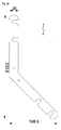
- this further comprises at least one angled connecting element (5).
- the angled connecting element (5) is designed as two-legged or three-legged or four-legged.
- each leg (5a, 5b, 5c, 5d) of the angled connecting element (5) at least one recess (501) is provided whose diameter is greater than the diameter of the bolt (105) and smaller than the head (105c) of the bolt (105 ).
- the angled connecting elements (5) serve to connect two or three or four elements provided with the fitting system (100) according to the invention to each other at fixed or variable angles, i. about their attachment to an upper and / or lower narrow edge of these elements.
- the at least one recess (501) is open towards the edge from the middle of the respective limb (5a, 5b, 5c, 5d).
- the angled connecting element (5) can thus on a fitting (1) according to the invention with screwed bolt (105) are pushed from the side of the fitting (1).
- each leg (5a, 5b, 5c, 5d) which have a center distance which corresponds to the center distance of the first internal thread (101a) and the second internal thread (101b) of the main body (101st ) corresponds.
- two bolts (105) can be screwed into a fitting (1), which increases the stability of the connection.
- other fasteners such as threaded with union nut can be used.
- the recesses (501) in two adjacent legs (5a, 5b, 5c, 5d) are open to opposite sides.
- an angled connecting element (5) can be easily attached to initially provisionally erected elements, which are provided with the fitting system (100) according to the invention by being rotated about its center and thus pushed onto the bolts (105) or alternative fastening means .
- the recesses (501) in the legs (5a, 5b, 5c, 5d) are not aligned at right angles to the outer edge of the legs (5a, 5b, 5c, 5d), but on an imaginary circular path the rotation are to facilitate the postponement.
- An angled connecting element (5) with two legs (5a, 5b) can span an angle between 5 ° and 180 °, with fixed angles of 45 ° or 60 ° or 90 ° or 135 ° have proven to be practically useful.
- An angled connecting element (5) with three legs (5a, 5b, 5c) can each span an angle between 5 ° and 180 ° between two of its legs (5a, 5b, 5c), whereby the sum of the angles must be 360 °.
- Practically useful embodiments have angles of 180 ° / 90 ° / 90 ° and 120 ° / 120 ° / 120 °.
- An angled connecting element (5) with four legs (5a, 5b, 5c, 5d) can each span between two of its legs (5a, 5b, 5c) an angle between 5 ° and 175 °, the sum of the angles must be 360 ° ,
- a practically useful embodiment has angles of 90 ° / 90 ° / 90 °.
- a special embodiment of the angled connecting element (5) relates to a variable division of the angle, or the angle.
- the two or three or four legs (5a, 5b, 5c, 5d) adjustably connected to each other, so that almost any angle can be adjusted depending on the requirements.
- two legs (5a, 5b) may be connected to a releasable threaded screw which may be tightened to set a particular angle.
- the third aspect of the present invention relates to a modular partition system (300) comprising at least two planar elements (7) and at least two inventive hardware systems (100) as described above.
- the at least two planar elements (7) each have recesses (703) for receiving the fitting systems (100) at least in their mutually facing side surfaces (701), wherein a fitting (1) of a fitting system (100) is introduced into each recess (703) is, so that the at least two planar elements (7) by means of the at least two fitting systems (100) are mutually reversibly connectable.
- the modular partition wall system (300) represents a simple and thus cost-effective and very flexible system, with the partition walls depending on the requirements quickly and reversibly, for example, for trade fairs and exhibitions, can be constructed.
- the assembly work and the scope of the required parts and elements and tools is significantly reduced compared to conventional systems, thus reducing the logistical requirements in the construction.
- the Modular Partition System (300) In addition to a use for fairs and exhibitions in which lighter versions of the Modular Partition System (300) can be used, for example, the subdivision of shelters with a more stable version of the modular partition system (300), preferably with sound and / or thermal insulation properties, a In addition, the modular partition wall system (300) for shop fitting, so-called "shop-in-shop” arrangements, the interior design or the variable structure in open-plan offices can be used.
- Sheet-like elements is understood to mean elements whose two-dimensional extent is at least one order of magnitude of the unit of measurement over their thickness.
- sheet-like elements (7) are, above all, wall elements, specifically wall elements which are constructed temporarily.
- the flat elements (7) according to the invention have an inner frame (707), which preferably consists of glued-in solid wood, the corners of which are mitred and correspondingly joined.
- inner frame (707) preferably consists of glued-in solid wood, the corners of which are mitred and correspondingly joined.
- plastic profiles or metal profiles can be used, for example plastic profiles or metal profiles.
- metal profiles for example aluminum profiles, can be provided directly with at least one oblong hole (103l) with a centrally arranged circular opening (103c).
- planar elements (7) according to the invention have the advantage that they are light, thin and quick to assemble and disassemble and require less storage space or storage space when not in use.
- a cover layer is applied on both sides, which may also consist of different materials depending on the purpose.
- high density fibreboard (HDF) or medium density fibreboard (MDF) with colored decoration or natural colors (can be painted over) are preferred.
- high-pressure laminates (HPL "High Pressure Laminate") or acoustic panels, possibly with micro-perforation, can be used as cover layer.
- the space between the cover layers can be filled with different materials depending on the purpose.
- preferred for use in trade fair construction is a filling of a hemp / kenaf laminate in wave form (available from the company Lisocore).
- honeycomb structures made of cardboard or plastic, in particular flame-retardant, foams made of polystyrene or polyurethane or fiber materials such as rock wool or glass wool can be used.
- the side surfaces (701) of the flat elements (7), ie the outer sides of the inner frame (709) are provided with recesses (703) for receiving the fitting systems (100).
- elongated holes (703l) and blind holes (703b) are introduced, which correspond to the outer dimensions of the fittings (1) according to the invention.
- a deeper blind hole (703b) is provided for each fitting (1), which can accommodate the base body (101) of the fitting (1), while a less deep slot (703l) is provided for receiving the striking plate (103).
- bores or grains may be provided at the level of the first connection hole (103g) and / or the second connection hole (103h) in the strike plate (103) in order to screw or connect the fitting (1) to the planar element (7). to facilitate.
- planar elements (7) are rectangular.
- a special embodiment are square flat elements (7).
- flat elements (7) are rectangles, which have two shorter side surfaces (701 k) and two longer side surfaces (701l).
- the planar elements (7) each have two recesses (703) for receiving the fitting systems (100).
- the recesses (703) have a predetermined distance (A) from the corner of the sheet-like element (7).
- the flat elements (7) also each have two recesses (703) for receiving the fitting systems (100), which also have a fixed distance (A) from the corner of the sheet element (7).
- the flat elements (7) at least in their longer side surfaces (701l) in the middle each have an auxiliary recess (705) for receiving the auxiliary bolt (3).
- auxiliary longitudinal holes (705l) and auxiliary blind holes (705b) are provided for this purpose.
- an auxiliary bolt (3) is inserted, which slides for flush alignment and guiding first in the auxiliary long hole (705l) of another flat element (7), before adjusting in the auxiliary blind hole (705b) is recorded.
- fittings (1) of a first sheet-like element (7) is now in each case a screw bolt (105) screwed into an internal thread (101 a, 101 b), in each case in the upper internal thread (101 a).
- a second planar element (7) which is to be attached to the first planar element (7), no bolts (105) are screwed.
- the screw bolts (105) can not be screwed into the first planar element (7) but into the second planar element (7), then in each case in particular into the lower internal thread (10 1 b).
- the heads (105c) of the screw bolts (105) are now inserted into the opposite circular openings (103c) of the striking plate (103) and then the second planar element (7) is displaced in the longitudinal direction against the first planar element (7), in a concrete embodiment from above down, that the two bolts (105) in the slots (1031) to slide until the stop and finally connect the two flat elements (7) firmly, but reversibly.
- first bolt (105) in two adjacent fittings (1) of the two flat elements (7) are screwed in and then an angled connecting element ( 5) with its recess (501) pushed or pushed.
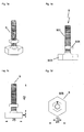
- the modular partition wall system (300) may further comprise one or more foot elements (9) which can be screwed into the at least one first internal thread (101a) of the base body (101) of the fitting (1).
- the modular partition wall system (300) may further comprise one or more brackets, which are screwed into the at least one first internal thread (101a) of the base body (101) of the fitting (1).
- the modular partition system (300) may further include at least one corner member (11) having at least one smooth side surface (1101) and two open side surfaces (1103), each open side surface (1103) having two recesses each with a slot (1103l) and a centrally disposed circular opening (1103c) which correspond to the oblong hole (103l) and the circular opening (103c) of the striking plate (103) of the fitting (1).
- the foot elements (9) preferably consist of a thread (901) matching the internal thread (101a, 101b), in particular an M8 thread, and a base plate (903) attached thereto.
- the foot elements (9) serve to support the individual sheet-like elements (7) on the ground.
- the thread (901) By the thread (901), the foot elements (9) in the internal thread (101 a, 101 b) also adjustable in height, so that the modular partition system (300) can be well aligned even on uneven ground.
- a lock nut (905) is preferably further provided, which is tightened after alignment. By means of the lock nut (905) and the angled connecting elements (5) can be tightened after being pushed.
- the brackets can preferably be screwed into the fittings (1) provided in the upper side surface (701) and, for example, inserted Include lighting system for the flat elements (7) or roof elements.
- Other devices that can be attached to the brackets are guards, picture frame rails, suspensions, construction frames, cable guides, and the like.
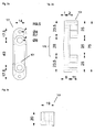
- FIG. 1 a fitting 1 according to the invention is shown schematically and exploded in perspective, from which the arrangement of base 101, strike plate 103 and bolt 105 is clear.
- the internal threads 101a, 101b for receiving, inter alia, the bolt 105 are preferably M8 thread.
- the connection receptacles 101e, 101f, which are preferably designed as internal threads, are in particular M4 threads.
- FIGS. 2a to 2c The dashed lines above and below the circular opening 103c are adjacent to the tapered portion 103j in which the striking plate 103 in this concrete form tapers from 3 mm in thickness to 2 mm in thickness is.
- FIGS. 3a to 3c illustrate a main body 101 schematically in plan view and in sectional views.
- FIG. 4 is a schematic cross-sectional view of a fitting 1 with screwed screw 105. Between body 101 and closing plate 103 two elastic elements 107 are provided.
- a bolt 105 is in the FIGS. 5a to 5d shown schematically,
- FIGS. 6a to 6e exemplify some of these embodiments schematically.
- FIGS. 7a to 7d schematically show a foot member 9 in an embodiment of the invention.
- FIG. 8 A specific embodiment of the planar element 7 is shown in FIG. 8 shown schematically in a plan view.
- auxiliary recesses 705 are provided centrally in all side surfaces 701k, 7011.
- the recess 703 and the auxiliary recess 705 are shown schematically in plan view and in sectional views.
- FIGS. 11a bis11d show a corner element 11 according to an embodiment of the invention, wherein FIG. 11a is a cross-sectional view from above and FIG. 11b a side view and a perspective shows.
- FIG. 11c provide a recess Slot 11031 and circular opening 1103c, which correspond to the slot 103l and the circular opening 103c.
- FIG. 11d schematically shows an auxiliary recess 1103b.
Landscapes
- Engineering & Computer Science (AREA)
- Architecture (AREA)
- Physics & Mathematics (AREA)
- Electromagnetism (AREA)
- Civil Engineering (AREA)
- Structural Engineering (AREA)
- Connection Of Plates (AREA)
- Joining Of Building Structures In Genera (AREA)
Abstract
- einen Grundkörper (101), der eine langlochförmige Vertiefung (101l), zumindest ein erstes Innengewinde (101a) und zumindest eine erste Verbindungsaufnahme (101e) aufweist, und
- ein Schließblech (103), das ein Langloch (103a) mit einer mittig angeordneten kreisförmigen Öffnung (103c) und zumindest eine erste Verbindungsdurchführung (103e) aufweist,
wobei der Grundkörper (101) und das Schließblech (103) durch zumindest ein Verbindungsmittel (109) lösbar miteinander verbunden sind.
Description
- Die vorliegende Erfindung bezieht sich auf einen Beschlag und ein Beschlagsystem zum reversiblen Verbinden von flächigen Elementen sowie ein modulares Stellwandsystem, die unter anderem im Messebau Anwendung finden.
- Beschläge und Beschlagsysteme sowie Stellwandsysteme sind aus dem Stand der Technik an sich bekannt. Beispielsweise beschreibt
DE 299 19 265 U1 eine Stellwandanordnung, die so aufgebaut ist, dass ein Beschlagteil dem einen Stellwandelement zugeordnet wird, während ein anderes Beschlagteil dem anderen Stellwandelement zugeordnet wird. Ein Verbindungsbolzen dient dazu, die beiden Beschlagteile und damit die beiden Stellwandelemente miteinander zu verbinden. Der Bolzen wird mit seinem Kopf in den Schlitz in dem Beschlagteil eingeführt. Durch Verdrehen des Beschlagteils wird wegen der zunehmenden Wandstärke des Beschlagteils ein Zug auf den Kopf und damit auf den Bolzen ausgeübt, was zur Festlegung der beiden Stellwandelemente aneinander führt. - Dieses sowie auch andere bekannte Systeme weisen den Nachteil auf, dass zum Verbinden von Stellwandelementen mehrteilige und teilweise komplexe Beschläge eingesetzt werden müssen, die in der Handhabung bedienungsintensiv sind und spezielle Werkzeuge benötigen. Für viele Systeme sind zudem Rahmenkonstruktionen erforderlich, was nicht nur die Optik beeinträchtigt, sondern auch die Kosten für das einzelne Stellwandelement erhöht.
- Der vorliegenden Erfindung liegt daher die Aufgabe zugrunde, einen Beschlag und ein Beschlagsystem bereitzustellen, welche die Nachteile des Standes der Technik überwinden und eine einfache und robuste Möglichkeit bieten, flächige Elemente reversibel zu verbinden. Gleichzeitig soll ein einfaches und kostengünstiges modulares Stellwandsystem zur Verfügung gestellt werden, das einerseits leicht aber stabil ist und andererseits schnell auf- und abgebaut werden kann.
- Diese Aufgabe wird in einem ersten Aspekt der vorliegenden Erfindung durch einen Beschlag (1) zum reversiblen Verbinden von flächigen Elementen (7) gelöst, umfassend
- einen Grundkörper (101), der eine langlochförmige Vertiefung (1011), zumindest ein erstes Innengewinde (101a) und zumindest eine erste Verbindungsaufnahme (101e) aufweist, und
- ein Schließblech (103), das ein Langloch (103l) mit einer mittig angeordneten kreisförmigen Öffnung (103c) und zumindest eine erste Verbindungsdurchführung (103e) aufweist,
- In einem zweiten Aspekt der vorliegenden Erfindung wird die Aufgabe durch ein Beschlagsystem (100) zum reversiblen Verbinden von flächigen Elementen (7) gelöst, umfassend
- zumindest zwei erfindungsgemäße Beschläge (1) und
- zumindest einen Schraubbolzen (105), der an seinem ersten Ende ein zu dem ersten Innengewinde (101a) des Grundkörpers (101) passendes Außengewinde (105a) und an seinem zweiten Ende einen Kopf (105c) aufweist, dessen Durchmesser kleiner als der Durchmesser der kreisförmigen Öffnung (103c) des Schließblechs (103) und größer als die Breite des Langlochs (103l) in dem Schließblech (103) ist,
- Die Aufgabe wird ferner in einem dritten Aspekt der vorliegenden Erfindung durch ein modulares Stellwandsystem (300) gelöst, umfassend
- zumindest zwei flächige Elemente (7) und
- zumindest zwei erfindungsgemäße Beschlagsysteme (100),
- Im Folgenden wird die Erfindung im Detail beschrieben. Vorteile und Ausführungsformen, die in Bezug auf einen der drei vorstehend genannten Aspekte beschrieben werden, gelten für die beiden anderen vorstehend genannten Aspekte entsprechend.
- Der erste Aspekt der vorliegenden Erfindung bezieht sich auf einen Beschlag (1) zum reversiblen Verbinden von flächigen Elementen (7). Der Beschlag (1) umfasst einen Grundkörper (101), der eine langlochförmige Vertiefung (101l), zumindest ein erstes Innengewinde (101a) und zumindest eine erste Verbindungsaufnahme (101e) aufweist. Der Beschlag (1) umfasst ferner ein Schließblech (103), das ein Langloch (103l) mit einer mittig angeordneten kreisförmigen Öffnung (103c) und zumindest eine erste Verbindungsdurchführung (103e) aufweist. Dabei sind der Grundkörper (101) und das Schließblech (103) durch zumindest ein Verbindungsmittel (109) lösbar miteinander verbunden.
- Der Grundkörper (101) ist bevorzugt länglich ausgebildet und weist vorzugsweise neben dem ersten Innengewinde (101a) ein zweites Innengewinde (101b) auf. Die Innengewinde (101a, 101b) sind vorzugsweise M8-Gewinde. Der Grundkörper (101) ist insbesondere über die Mitte seiner Längsachse und über die Mitte seiner Querachse jeweils spiegelsymmetrisch ausgebildet. Ferner weist der Grundkörper (101) neben der ersten Verbindungsaufnahme (101e) vorzugsweise eine weitere zweite Verbindungsaufnahme (101f) auf. Die erste und zweite Verbindungsaufnahme (101e, 101f) sind in Längsrichtung außen neben dem ersten Innengewinde (101a) und dem zweiten Innengewinde (101b) angeordnet. Die langlochförmige Vertiefung (101l) ist breiter als das Langloch (103l) des Schließblechs (103) und breiter als der Kopf (105c) eines Schraubbolzens (105).
- Das Schließblech (103) ist bevorzugt ebenfalls länglich ausgebildet und ist insbesondere über die Mitte seiner Längsachse und über die Mitte seiner Querachse jeweils spiegelsymmetrisch ausgebildet. Es hat vorzugsweise die gleiche Breite wie der Grundkörper (101), jedoch eine größere Länge als der Grundkörper (101). Das Langloch (103l) ist in dem Schließblech (103) in Längsrichtung angeordnet. Mittig in dem Langloch (103l) ist eine kreisförmige Öffnung (103c) vorgesehen, deren Durchmesser größer ist als die Breite des Langlochs (103l). Der Durchmesser der kreisförmigen Öffnung (103c) entspricht der Breite der langlochförmigen Vertiefung (101l). Das Schließblech (103) weist ferner zumindest eine erste Verbindungsdurchführung (103e), und bevorzugt eine zweite Verbindungsdurchführung (103f), auf. Vorzugsweise sind in Längsrichtung im Bereich der Enden, die über den Grundkörper (101) hinausstehen, zwei Verbindungslöcher (103g, 103h) vorgesehen.
- Um den Grundkörper (101) und das Schließblech (103) miteinander zu verbinden, werden diese so aufeinander gelegt, dass das Langloch (1031) an einem Ende zumindest das erste Innengewinde (101a) und vorzugsweise an seinem anderen Ende das zweite Innengewinde (101b) freilässt. Zudem fluchten das Langloch (103l) und die langlochförmige Vertiefung (1011) miteinander, Ferner werden zumindest die erste Verbindungsaufnahme (101e) des Grundkörpers (101) und die erste Verbindungsdurchführung (103e) des Schließblechs (103) zur Deckung gebracht - vorzugsweise auch die zweite Verbindungsaufnahme (101e) und die zweite Verbindungsdurchführung (103e). Durch das Verbindungsmittel (109), bevorzugt zwei, werden der Grundkörper (101) und das Schließblech (103) miteinander verbunden. In einer konkreten Ausführungsform der Erfindung ist das Verbindungsmittel (109) eine Gewindeschraube, insbesondere mit M4-Gewinde, die durch die erste Verbindungsdurchführung (103e) in die als Innengewinde, insbesondere als M4-Gewinde, ausgestaltete erste Verbindungsaufnahme (101e) geschraubt wird. Gleiches gilt für das Durchführen eines Verbindungsmittels (109) durch die zweite Verbindungsdurchführung (103e) und das Einschrauben in die zweite Verbindungsaufnahme (101e).
- Der Grundkörper (101) und das Schließblech (103) bilden im Bereich von langlochförmiger Vertiefung (101l) und Langloch (103l) einen Hinterschnitt, in den der Kopf (105c) eines Schraubbolzens (105), der nachstehend noch beschrieben wird, eingreifen kann.
- Der Beschlag (1) ist dazu ausgelegt, in eine entsprechend vorbereitete Aussparung (701 a) des flächigen Elements (7) eingebracht zu werden, so dass dieser grundsätzlich in Bezug auf die Vorderseite bzw. Rückseite des flächigen Elements (7) verdeckt ist. Zum Befestigen des Beschlags (1) an dem flächigen Element (7) sind die vorstehend erwähnten Verbindungslöcher (103g, 103h) vorgesehen, durch welche Befestigungsmittel, beispielsweise Schrauben, geführt und in dem flächigen Element (7) befestigt, beispielsweise verschraubt, werden können.
- Bevorzugte Maße des Beschlags (1) und seiner Einzelteile werden in den Figuren als bevorzugte Ausführungsformen definiert, ohne die Erfindung jedoch auf diese Maße einzuschränken.
- Der erfindungsgemäße Beschlag (1) ist in vorteilhafter Weise einfach und damit kostengünstig aufgebaut und lässt sich in großer Stückzahl günstig produzieren. Anders als im Stand der Technik sind durch den erfindungsgemäßen Beschlag (1) keine zueinander komplementären Beschlagteile, d.h. Positiv- und Negativteile, erforderlich. Er ist ferner sehr einfach an einem flächigen Element (7) zu befestigen. Nach dem Befestigen stehen keine Teile über die Ränder des flächigen Elements (7) hinaus, so dass die Verletzungsgefahr für Personen deutlich verringert wird. Zudem ist der Beschlag (1) auch als Verbindungsbeschlag im Rahmenbau einsetzbar, wo wieder lösbare Verbindungen benötigt werden.
- In einer bevorzugten Ausführungsform der Erfindung umfasst der Beschlag (1) ferner einen Schraubbolzen (105), der an seinem ersten Ende ein zu dem ersten Innengewinde (101a) des Grundkörpers (101) passendes Außengewinde (105a), insbesondere ein M8-Gewinde, und an seinem zweiten Ende einen Kopf (105c) aufweist, dessen Durchmesser kleiner als der Durchmesser der kreisförmigen Öffnung (103c) des Schließblechs (103) und größer als die Breite des Langlochs (103l) in dem Schließblech (103) ist.
- Das Außengewinde (105a) ist in einer Ausführungsform über den größten Teil der Länge des Schraubbolzens (105) ausgebildet. So ist es möglich, durch gezieltes Ein- und Ausdrehen des Schraubbolzens (105) abweichende Materialdicken, beispielsweise durch Verschleiß, oder materialbedingtes Schwundverhalten auszugleichen. Ferner weist der Schraubbolzen (105) zwischen dem Kopf (105c) und dem Außengewinde (105a) einen glatten Bereich (105l) auf, der das Gleiten des Schraubbolzens (105) in dem Langloch (1031) des Schließblechs (103) erleichtert.
- Andererseits kann das Außengewinde (105a) nicht über die gesamte Länge des Schraubbolzens (105) ausgebildet sein und insbesondere am Übergang vom Außengewinde (105a) zum glatten Bereich (1051) einen Anschlag aufweisen, der ein weiteres Eindrehen in das erste Innengewinde (101a) des Grundkörpers (101) verhindert.
- Der Kopf (105c) kann eine Werkzeugaufnahme (105w) aufweisen, beispielsweise einen Schlitz, einen Kreuzschlitz, einen Innensechskant (sog. "Inbus"), einen Außensechskant, ein Schrauben-Mitnahmeprofil in Vielrundform (sog. "Torx") oder dergleichen.
- Durch das Einschrauben des Schraubbolzens (105) in einen Beschlag (1) wird eine einfache und robuste Möglichkeit geschaffen, diesen Beschlag (1) mit einem weiteren Beschlag (1) ohne eingeschraubten Schraubbolzen (105) zu verbinden.
- Dabei wird der Kopf (105c) des Schraubbolzens (105), der in den einen Beschlag (1) eingeschraubt ist, in die kreisförmige Öffnung (103c) des Schließblechs (103) des anderen Beschlags eingeführt und beide Beschläge (1) in Längsrichtung gegeneinander verschoben, so dass der Schraubbolzen (105) in einen Teil des Langlochs (1031) gleitet und an dessen Ende anschlägt. Durch den gegenüber der Breite des Langlochs (103l) größeren Durchmesser des Kopfs (105c) werden beide Beschläge (1) aneinander gehalten.
- Auf diese Weise kann das nachstehend noch im Detail beschriebene Beschlagsystem (100) erhalten werden.
- Es ist in einer Weiterbildung der Erfindung bevorzugt, wenn das Schließblech (103) des Beschlags (1) zu der kreisförmigen Öffnung (103c) hin einen verjüngten Bereich (103j) aufweist. Das bedeutet, dass die Dicke des Schließblechs (103) in Längsrichtung in dem verjüngten Bereich (103j) an der kreisförmigen Öffnung (103c) geringer ist als an den Enden, wobei die Dicke kontinuierlich zunimmt, bzw. abnimmt. Die Verringerung der Dicke des Schließblechs (103) in dem verjüngten Bereich (103j) beträgt 20 % bis 50 %, bevorzugt 30 % bis 35 %. Der verjüngte Bereich (103j) ist nur auf der dem Grundkörper (101) zugewandten Seite des Schließblechs (103) vorhanden. Zudem kann der Grundkörper (101) komplementär zu dem verjüngten Bereich (103j) einen ausgebauchten Bereich (101j) aufweisen.
- Durch diese Weiterbildung ist es möglich, beim Verbinden eines Beschlags (1) mit eingeschraubtem Schraubbolzen (105) und eines Beschlags (1) ohne eingeschraubten Schraubbolzen (105) zunächst das Einführen des Kopfs (105c) des Schraubbolzens (105) in die kreisförmige Öffnung (103c) des Schließblechs (103) zu erleichtern und dann beim Einschieben des Schraubbolzens (105) in das Langloch (103l) des Schließblechs (103) beide Beschläge fest aneinander zu ziehen.
- Es ist ferner bevorzugt, wenn in einer anderen Weiterbildung zwischen dem Grundkörper (101) und dem Schließblech (103) zumindest ein elastisches Element (107) angeordnet ist. Dabei ist das elastische Element (107) insbesondere im Bereich der ersten Verbindungsaufnahme (101e) des Grundkörpers (101) und der ersten Verbindungsdurchführung (103e) des Schließblechs (103) vorgesehen - insbesondere auch im Bereich zweite Verbindungsaufnahme (101f) / zweite Verbindungsdurchführung (103f). In einer konkreten Ausführungsform ist das elastische Element (107) ein Gummiring.
- Abhängig von der Dicke des elastischen Elements (107) ergibt sich bei dem vorstehend beschriebenen Aneinanderziehen zweier Beschläge (1) ein elastisch bedingtes Spiel von 0,5 mm bis 2,0 mm, welches das feste Aneinanderziehen weiter unterstützt.
- In dem zweiten Aspekt betrifft die vorliegende Erfindung ein Beschlagsystem (100) zum reversiblen Verbinden von flächigen Elementen (7). Das Beschlagsystem (100) umfasst zumindest zwei erfindungsgemäße Beschläge (1), wie sie vorstehend beschrieben wurden, und zumindest einen Schraubbolzen (105).
- Wie vorstehend schon ausgeführt, weist der Schraubbolzen (105) an seinem ersten Ende ein zu dem ersten Innengewinde (101a) des Grundkörpers (101) passendes Außengewinde (105a) und an seinem zweiten Ende einen Kopf (105c) auf, dessen Durchmesser kleiner als der Durchmesser der kreisförmigen Öffnung (103c) des Schließblechs (103) und größer als die Breite des Langlochs (103l) in dem Schließblech (103) ist.
- Für das Beschlagsystem (100) ist der Schraubbolzen (105) in einen der zumindest zwei Beschläge (1) eingeschraubt.
- Es wurde vorstehend schon ausgeführt, dass beim Verbinden von zwei erfindungsgemäßen Beschlägen (1) der Kopf (105c) des Schraubbolzens (105), der in den einen Beschlag (1) eingeschraubt ist, in die kreisförmige Öffnung (103c) des Schließblechs (103) des anderen Beschlags (1) ohne eingeschraubten Schraubbolzen (105) eingeführt wird und dann beide Beschläge (1) in Längsrichtung gegeneinander verschoben werden. Folglich gleitet der Schraubbolzen (105) in einen Teil des Langlochs (1031) und schlägt an dessen Ende an, wodurch die endgültige Verbindungsposition der beiden Beschläge (1) erreicht wird. Durch den gegenüber der Breite des Langlochs (1031) größeren Durchmesser des Kopfs (105c) werden beide Beschläge (1) aneinander gehalten.
- Es ergibt sich der Vorteil, dass das Beschlagsystem (100) eine einfache und robuste Möglichkeit darstellt, zwei erfindungsgemäße Beschläge (1) miteinander zu verbinden und damit auch zwei Elemente, in denen die erfindungsgemäßen Beschläge (1) aufgenommen sind, reversibel, d.h. wieder lösbar, zu verbinden. Aus Gründen der Stabilität werden zum Verbinden von zwei Elementen vorzugsweise zwei erfindungsgemäße Beschlagsysteme (100), d.h. vier erfindungsgemäße Beschläge (1) mit zwei Schraubbolzen (105) eingesetzt.
- Ein weiterer Vorteil des Beschlagsystems (100) ist, dass nur eine Art von Beschlag (1) vorgesehen ist und nicht wie im Stand der Technik mindestens zwei sich ergänzende Beschläge. Lediglich durch Einschrauben des Schraubbolzens (105) wird einer der Beschläge (1) zur Positiv- (oder Negativ-) Form. Die Anzahl der herzustellenden und einzusetzenden Teile verringert sich daher deutlich, was die Kosten senkt. Gleichzeitig wird die Variabilität des Beschlagsystems (100) gegenüber dem Stand der Technik erhöht.
- Die durch das erfindungsgemäße Beschlagsystem (100) zu verbindenden Elemente sind vielfältig und schließen insbesondere flächige Elemente (7) wie Stellwände und dergleichen ein. Es können aber mit dem erfindungsgemäßen Beschlagsystem (100) auch Elemente im Rahmenbau, ggf. mit Stoff bespannt, Bodenplatten, Deckenplatten, Akustikpaneele oder feste Wände für Notunterkünfte (mit Dämmeigenschaften) reversibel miteinander verbunden werden.
- In einer vorteilhaften Ausführungsform umfasst das Beschlagsystem (100) ferner zumindest einen Hilfsbolzen (3), der dazu ausgelegt Ist, in ein Hilfssackloch (705b) einer Hilfsaussparung (705) aufgenommen zu werden, wobei der Durchmesser des Hilfsbolzens (3) dem Durchmesser des Hilfssacklochs (705b) entspricht.
- Das Vorsehen des Hilfsbolzens (3) dient in vorteilhafter Weise dazu, beim Verbinden von größeren Elementen, d.h. Elementen mit längeren Kanten, mittels des erfindungsgemäßen Beschlagsystems (100) das bündige Ausrichten, das Führen und das Justieren dieser größeren Elemente zu erleichtern, ohne andererseits ein weiteres. Beschlagsysteme (100) vorsehen zu müssen. Es wird eine einfache, aber wirkungsvolle Führung geschaffen, die das Verbinden der erfindungsgemäßen Beschläge (1) erleichtert. In Verbindung mit dem dritten Aspekt sowie in den Ausführungsbeispielen wird hierauf noch im Detail eingegangen.
- In einer Weiterbildung des erfindungsgemäßen Beschlagsystems (100) umfasst dieses ferner zumindest ein winkliges Verbindungselement (5). Das winklige Verbindungselement (5) ist zweischenklig oder dreischenklig oder vierschenklig ausgestaltet. In jedem Schenkel (5a, 5b, 5c, 5d) des winkligen Verbindungselements (5) ist zumindest eine Aussparung (501) vorgesehen, deren Durchmesser größer als der Durchmesser des Schraubbolzens (105) und kleiner als der Kopf (105c) des Schraubbolzens (105) ist.
- Die winkligen Verbindungselemente (5) dienen dazu, zwei oder drei oder vier mit dem erfindungsgemäßen Beschlagsystem (100) versehene Elemente miteinander in festgelegten oder variablen Winkeln zueinander zu verbinden, d.h. über deren Befestigung an einer oberen und/oder unteren Schmalkante dieser Elemente.
- Die zumindest eine Aussparung (501) ist von der Mitte des jeweiligen Schenkels (5a, 5b, 5c, 5d) her zum Rand hin offen. Das winklige Verbindungselement (5) kann somit auf einen erfindungsgemäßen Beschlag (1) mit eingeschraubtem Schraubbolzen (105) von der Seite des Beschlags (1) aufgeschoben werden.
- Es ist bevorzugt, wenn zwei Aussparungen (501) in jedem Schenkel (5a, 5b, 5c, 5d) vorgesehen sind, die einen Mittenabstand aufweisen, welcher dem Mittenabstand von erstem Innengewinde (101 a) und zweitem Innengewinde (101b) des Grundkörpers (101) entspricht. Für diesen Fall können beispielsweise zwei Schraubbolzen (105) in einen Beschlag (1) eingeschraubt werden, was die Stabilität der Verbindung erhöht. Alternativ können andere Befestigungsmittel wie Gewinde mit Überwurfmutter verwendet werden.
- Vorzugsweise sind die Aussparungen (501) in zwei benachbarten Schenkeln (5a, 5b, 5c, 5d) zu entgegengesetzten Seiten hin geöffnet. Auf diese Weise kann ein winkliges Verbindungselement (5) problemlos an zunächst provisorisch aufgestellte Elemente, welche mit dem erfindungsgemäßen Beschlagsystem (100) versehen sind, angebracht werden, indem es über seine Mitte gedreht und damit auf die Schraubbolzen (105) oder alternative Befestigungsmittel aufgeschoben wird. Hierzu hat es sich ferner als vorteilhaft herausgestellt, wenn die Aussparungen (501) in den Schenkeln (5a, 5b, 5c, 5d) nicht rechtwinklig zur Außenkante der Schenkel (5a, 5b, 5c, 5d) ausgerichtet sind, sondern auf einer gedachten Kreisbahn der Drehung liegen, um das Aufschieben zu erleichtern.
- Ein winkliges Verbindungselement (5) mit zwei Schenkeln (5a, 5b) kann einen Winkel zwischen 5° und 180° aufspannen, wobei sich feste Winkel von 45° oder 60° oder 90° oder 135° als praktisch sinnvoll herausgestellt haben.
- Ein winkliges Verbindungselement (5) mit drei Schenkeln (5a, 5b, 5c) kann zwischen zwei seiner Schenkel (5a, 5b, 5c) jeweils einen Winkel zwischen 5° und 180° aufspannen wobei die Summe der Winkel 360° ergeben muss. Praktisch sinnvolle Ausgestaltungen weisen Winkel von 180°/90°/90° und 120°/120°/120° auf.
- Ein winkliges Verbindungselement (5) mit vier Schenkeln (5a, 5b, 5c, 5d) kann zwischen zwei seiner Schenkel (5a, 5b, 5c) jeweils einen Winkel zwischen 5° und 175° aufspannen, wobei die Summe der Winkel 360° ergeben muss. Eine praktisch sinnvolle Ausgestaltung weist Winkel von 90°/90°/90°/90° auf.
- Eine spezielle Ausgestaltung des winkligen Verbindungselements (5) betrifft eine variable Einteilung des Winkels, bzw. der Winkel. In dieser Ausgestaltung sind die zwei oder drei oder vier Schenkel (5a, 5b, 5c, 5d) verstellbar miteinander verbunden, so dass abhängig von den Erfordernissen nahezu beliebige Winkel eingestellt werden können. Beispielsweise können zwei Schenkel (5a, 5b) mit einer lösbaren Gewindeschraube verbunden sein, die zum Einstellen eines bestimmten Winkels festgezogen werden kann.
- Der dritte Aspekt der vorliegenden Erfindung betrifft ein modulares Stellwandsystem (300), das zumindest zwei flächige Elemente (7) und zumindest zwei erfindungsgemäße Beschlagsysteme (100), wie sie vorstehend beschrieben wurden, umfasst. Die zumindest zwei flächigen Elemente (7) weisen zumindest in ihren zueinander gewandten Seitenflächen (701) jeweils Aussparungen (703) zur Aufnahme der Beschlagsysteme (100) auf, wobei in jede Aussparung (703) ein Beschlag (1) eines Beschlagsystems (100) eingebracht ist, so dass die zumindest zwei flächigen Elemente (7) mittels der zumindest zwei Beschlagsysteme (100) untereinander reversibel verbindbar sind.
- Das modulare Stellwandsystem (300) gemäß der vorliegenden Erfindung stellt ein einfaches und damit kostengünstiges sowie sehr flexibles System dar, mit dem in Abhängigkeit von den Erfordernissen schnell und reversibel Stellwände, beispielsweise für Messen und Ausstellungen, aufgebaut werden können. Der Montageaufwand und der Umfang der benötigten Einzelteile und Elemente sowie Werkzeuge ist gegenüber herkömmlichen Systemen deutlich reduziert und verringert so die logistischen Anforderungen beim Aufbau.
- Neben einem Einsatz für Messen und Ausstellungen, bei denen leichtere Ausführungen des modularen Stellwandsystems (300) verwendet werden können, stellt beispielsweise die Unterteilung von Notunterkünften mit einer stabileren Version des modularen Stellwandsystems (300), vorzugsweise mit Schall- und oder Wärmedämm-Eigenschaften, ein weiteres Anwendungsgebiet dar. Zudem kann das modulare Stellwandsystems (300) für den Ladenbau, sog. "Shop-in-Shop"-Anordnungen, den Innenausbau oder die variable Gliederung in Großraumbüros eingesetzt werden.
- Unter "flächigen Elementen" werden Elemente verstanden, deren zweidimensionale Ausdehnung mindestens eine Größenordnung der Maßeinheit über deren Dicke liegt. Erfindungsgemäß sind flächige Elemente (7) vor allem Wandelemente, konkret Stellwandelemente, die temporär aufgebaut werden.
- Die erfindungsgemäßen flächigen Elemente (7) weisen einen innenliegenden Rahmen (707) auf, der vorzugsweise aus eingeleimtem Vollholz besteht, dessen Ecken auf Gehrung gesägt und entsprechend gefügt sind. Für den innenliegenden Rahmen (707) können aber abhängig vom Einsatzzweck andere Materialien Anwendung finden, beispielsweise Kunststoffprofile oder Metallprofile. Hier sind beispielsweise Aluminiumprofile mit Kederschiene zum Arretieren von Stoffbespannungen ein Einsatzgebiet. Femer können Metallprofile, bspw. Aluminiumprofile, direkt mit zumindest einem Langloch (103l) mit einer mittig angeordneten kreisförmigen Öffnung (103c) versehen werden.
- Die erfindungsgemäßen flächigen Elemente (7) weisen den Vorteil auf, dass sie leicht, dünn und schnell auf- und abbaubar sind und weniger Stauraum bzw. Lagerfläche benötigen, wenn sie nicht gebraucht werden.
- Auf den innenliegenden Rahmen (707) wird beidseitig eine Deckschicht aufgebracht, die ebenfalls abhängig vom Einsatzzweck aus unterschiedlichen Materialien bestehen kann. Erfindungsgemäß bevorzugt sind hochdichte Faserplatten (HDF) oder mitteldichte Faserplatten (MDF) mit farbigem Dekor oder naturfarben (überstreichbar). Ferner sind Hochdrucklaminate (HPL "High Pressure Laminate") oder Akustikpaneele, ggf. mit Mikroperforierung, als Deckschicht einsetzbar.
- Der Raum zwischen den Deckschichten kann je nach Einsatzzweck mit unterschiedlichen Materialien gefüllt sein. Erfindungsgemäß bevorzugt für die Anwendung im Messebau ist eine Füllig aus einem Hanf/Kenaf-Laminat in Wellenform (erhältlich von der Firma Lisocore). Ferner können Wabenstrukturen aus Pappe oder Kunststoff, insbesondere schwer entflammbare, Schaumstoffe aus Polystyrol oder Polyurethan oder Fasermaterialien wie Steinwolle oder Glaswolle verwendet werden.
- Die Seitenflächen (701) der flächigen Elemente (7), d.h. die Außenseiten des innenliegenden Rahmens (709), sind mit Aussparungen (703) zur Aufnahme der Beschlagsysteme (100) versehen. Im Fall des erfindungsgemäßen konkreten Ausführungsbeispiels sind Langlöcher (703l) und Sacklöcher (703b) eingebracht, welche den Außenabmessungen der erfindungsgemäßen Beschläge (1) entsprechen. Konkret wird für jeden Beschlag (1) ein tieferes Sackloch (703b) vorgesehen, welches den Grundkörper (101) des Beschlags (1) aufnehmen kann, während für die Aufnahme des Schließblechs (103) ein weniger tiefes Langloch (703l) vorgesehen wird. Darüber hinaus können Bohrungen oder Körnungen auf der Höhe des ersten Verbindungslochs (103g) und/oder des zweiten Verbindungslochs (103h) im Schließblech (103) vorgesehen werden, um das Verschrauben bzw. Verbinden des Beschlags (1) mit dem flächigen Element (7) zu erleichtern.
- In einer Weiterbildung des modularen Stellwandsystems (300) sind die flächigen Elemente (7) rechteckig ausgebildet. Eine spezielle Ausführungsform sind quadratische flächige Elemente (7). Erfindungsgemäß hauptsächlich vorgesehene flächige Elemente (7) sind Rechtecke, die zwei kürzere Seitenflächen (701 k) und zwei längere Seitenflächen (701l) aufweisen.
- In ihren kürzeren Seitenflächen (701k) weisen die flächigen Elemente (7) jeweils zwei Aussparungen (703) zur Aufnahme der Beschlagsysteme (100) auf. Die Aussparungen (703) haben einen festgelegten Abstand (A) von der Ecke des flächigen Elements (7).
- In ihren längeren Seitenflächen (7011) weisen die flächigen Elemente (7) ebenfalls jeweils zwei Aussparungen (703) zur Aufnahme der Beschlagsysteme (100) auf, die ebenfalls einen festgelegten Abstand (A) von der Ecke des flächigen Elements (7) haben.
- Zudem weisen die flächigen Elemente (7) zumindest in ihren längeren Seitenflächen (701l) mittig jeweils eine Hilfsaussparung (705) zur Aufnahme des Hilfsbolzens (3) auf. Im Fall des erfindungsgemäßen konkreten Ausführungsbeispiels sind hierfür Hilfslanglöcher (705l) und Hilfssacklöcher (705b) vorgesehen. In das Hilfssackloch (705b) eines flächigen Elements (7) wird ein Hilfsbolzen (3) eingesetzt, der zum bündigen Ausrichten und zum Führen zunächst in dem Hilfslangloch (705l) eines anderen flächigen Elements (7) gleitet, bevor er zum Justieren in dessen Hilfssackloch (705b) aufgenommen wird.
- Zum Aufbau des modularen Stellwandsystems (300) werden zunächst die flächigen Elemente (7) mit bereits eingebrachten Beschlägen (1) in der späteren Reihenfolge bereitgestellt. In die beiden in einer Seitenfläche (701) vorhandenen Beschläge (1) eines ersten flächigen Elements (7) wird nun jeweils ein Schraubbolzen (105) in ein Innengewinde (101 a, 101b) eingeschraubt, konkret jeweils in das obere Innengewinde (101a). In ein zweites flächiges Element (7), das an das erste flächige Element (7) angesetzt werden soll, werden keine Schraubbolzen (105) eingeschraubt. Alternativ können die Schraubbolzen (105) nicht in das erste flächige Element (7), sondern in das zweite flächige Element (7) eingeschraubt werden, dann konkret jeweils in das untere Innengewinde (10 1 b).
- Zum Verbinden werden nun die Köpfe (105c) der Schraubbolzen (105) in die gegenüberliegenden kreisförmigen Öffnungen (103c) des Schließblechs (103) eingeführt und dann das zweite flächige Element (7) in Längsrichtung so gegen das erste flächige Element (7) verschoben, in einer konkreten Ausführungsform von oben nach unten, dass die beiden Schraubbolzen (105) in den Langlöchern (1031) bis zum Anschlag gleiten und die beiden flächigen Elemente (7) schließlich fest, aber reversibel verbinden.
- Für den Fall, dass zwei flächige Elemente (7) nicht eben, sondern in einem Winkel zueinander verbunden werden sollen, werden zunächst Schraubbolzen (105) in zwei benachbarte Beschläge (1) der beiden flächigen Elemente (7) eingeschraubt und anschließend ein winkliges Verbindungselement (5) mit seiner Aussparung (501) aufgeschoben, bzw. eingeschoben.
- In einer weiteren Ausführungsform kann das modulare Stellwandsystems (300) ferner ein oder mehrere Fußelemente (9) umfassen, die in das zumindest eine erste Innengewinde (101a) des Grundkörpers (101) des Beschlags (1) einschraubbar sind.
- In einer anderen Ausführungsform kann das modulare Stellwandsystem (300) ferner ein oder mehrere Halterungen umfassen, die in das zumindest eine erste Innengewinde (101a) des Grundkörpers (101) des Beschlags (1) einschraubbar sind.
- In einer weiteren Ausführungsform kann das modulare Stellwandsystem (300) ferner zumindest ein Eckelement (11) umfassen, das zumindest eine glatte Seitenfläche (1101) und zwei durchbrochene Seitenflächen (1103) aufweist, wobei jede durchbrochene Seitenfläche (1103) zwei Aussparungen jeweils mit einem Langloch (1103l) und einer mittig angeordneten kreisförmigen Öffnung (1103c) aufweist, welche dem Langloch (103l) und der kreisförmigen Öffnung (103c) des Schließblechs (103) des Beschlags (1) entsprechen.
- Die Fußelemente (9) bestehen vorzugsweise aus einem zu dem Innengewinde (101a, 101b) passenden Gewinde (901), insbesondere ein M8-Gewinde, und einer daran angebrachten Standplatte (903). Die Fußelemente (9) dienen dazu, die einzelnen flächigen Elemente (7) auf dem Untergrund abzustützen. Durch das Gewinde (901) sind die Fußelemente (9) in dem Innengewinde (101a, 101 b) zudem höhenverstellbar, so dass das modulare Stellwandsystem (300) auch bei unebenen Untergründen gut ausgerichtet werden kann. Um die Fußelemente (9) arretieren zu können, ist vorzugsweise ferner eine Kontermutter (905) vorgesehen, die nach dem Ausrichten festgezogen wird. Mittels der Kontermutter (905) können auch die winkligen Verbindungselemente (5) nach ihrem Aufschieben festgezogen werden.
- Die Halterungen können vorzugsweise in die in der oberen Seitenfläche (701) vorgesehenen Beschläge (1) eingeschraubt werden und beispielsweise ein Beleuchtungssystem für die flächigen Elemente (7) oder Dachelemente aufnehmen. Weitere Vorrichtungen, die an den Halterungen befestigt werden können, sind Abspannungen, Bilderrahmenschienen, Abhängungen, Konstruktionsrahmen, Kabelführungen und dergleichen.
- Weitere Ziele, Merkmale, Vorteile und Anwendungsmöglichkeiten ergeben sich aus der nachfolgenden Beschreibung von die Erfindung nicht einschränkenden Ausführungsbeispielen anhand der Figuren. Dabei bilden alle beschriebenen und/oder bildlich dargestellten Merkmale für sich oder in beliebiger Kombination den Gegenstand der Erfindung, auch unabhängig von ihrer Zusammenfassung in den Ansprüchen oder deren Rückbeziehung. Es zeigen:
- Fig. 1
- eine schematische perspektivische Explosionsdarstellung eines Beschlags 1 in einer Ausführungsform der Erfindung,
- Fig. 2a - c
- schematische Darstellungen eines Schließblechs 103,
- Fig. 3a - c
- schematische Darstellungen eines Grundkörpers 101,
- Fig. 4
- eine schematische Darstellung eines Beschlags 1 im Querschnitt in einer Ausführungsform der Erfindung mit eingeschraubtem Schraubbolzen 105,
- Fig. 5a - d
- schematische Darstellungen eines Schraubbolzens 105,
- Fig. 6a - e
- schematische Darstellungen von winkligen Verbindungselementen 5 nach verschiedenen Ausführungsformen der Erfindung,
- Fig. 7a - d
- schematische Darstellungen eines Fußelements 9 in einer Ausführungsform der Erfindung
- Fig.8
- eine schematische Darstellung eines flächigen Elements 7 in einer Ausführungsform der Erfindung,
- Fig. 9a + b
- schematische Darstellungen einer Aussparung 703 in einer Ausführungsform der Erfindung,
- Fig. 10a + b
- schematische Darstellungen einer Hilfsaussparung 705 in einer Ausführungsform der Erfindung und
- Fig. 11a - d
- schematische Darstellungen eines Eckelements 11.
- In den Figuren werden gleiche Teile mit den gleichen Bezugszeichen versehen und zur besseren Übersichtlichkeit in einigen Figuren nicht alle Bezugszeichen angegeben. Die Figuren sind ferner Prinzipdarstellungen, in denen die angegebenen Maße (in Millimetern) konkrete bevorzugte Ausführungsformen darstellen, welche die Erfindung nicht einschränken.
- In
Figur 1 ist ein erfindungsgemäßer Beschlag 1 schematisch und perspektivisch explosionsartig dargestellt, woraus die Anordnung von Grundkörper 101, Schließblech 103 und Schraubbolzen 105 deutlich wird. Die Innengewinde 101a, 101b zur Aufnahme u.a. des Schraubbolzens 105 sind vorzugsweise M8-Gewinde. Die vorzugsweise als Innengewinde ausgelegten Verbindungsaufnahmen 101e, 101f sind insbesondere M4-Gewinde. -
Figuren 2a bis 2c stellen ein Schließblech 103 schematisch in der Draufsicht und in Schnittansichten dar. Die gestrichelten Linien oberhalb und unterhalb der kreisförmigen Öffnung (103c) grenzen den verjüngten Bereich 103j ein, in welchem das Schließblech 103 in dieser konkreten Form von 3 mm Dicke auf 2 mm Dicke verjüngt ist. -
Figuren 3a bis 3c stellen einen Grundkörper 101 schematisch in der Draufsicht und in Schnittansichten dar. -
Figur 4 ist eine schematische Querschnittsansicht eines Beschlags 1 mit eingeschraubtem Schraubbolzen 105. Zwischen Grundkörper 101 und Schließblech 103 sind zwei elastische Elemente 107 vorgesehen. - Ein Schraubbolzen 105 wird in den
Figuren 5a bis 5d schematisch dargestellt, - Vorstehend wurden verschiedene Ausführungsformen von winkligen Verbindungselementen 5 bereits beschrieben.
Figuren 6a bis 6e stellen beispielhaft einige dieser Ausführungsformen schematisch dar. -
Figuren 7a bis 7d zeigen schematisch ein Fußelement 9 in einer Ausführungsform der Erfindung. - Eine spezielle Ausführungsform des flächigen Elements 7 wird in
Figur 8 in einer Draufsicht schematisch dargestellt. In dieser Ausführungsform sind Hilfsaussparungen 705 mittig in allen Seitenflächen 701k, 7011 vorgesehen. - In den
Figuren 8 und9 werden erfindungsgemäße Ausführungsformen der Aussparung 703 und der Hilfsaussparung 705 schematisch in der Draufsicht und in Schnittansichten dargestellt. -
Figuren 11a bis11d zeigen ein Eckelement 11 nach einer Ausführungsform der Erfindung, wobeiFigur 11a eine Querschnittsansicht von oben ist undFigur 11b eine Seitenansicht und eine Perspektive zeigt.Figur 11c stellen eine Aussparung mit Langloch 11031 und kreisförmiger Öffnung 1103c dar, welche dem Langloch 103l und der kreisförmigen Öffnung 103c entsprechen.Figur 11d zeigt schematisch eine Hilfsaussparung 1103b. -
- 1
- Beschlag
- 3
- Hilfsbolzen
- 5
- winkliges Verbindungselement
- 5a
- Schenkel des winkligen Verbindungselements 5
- 5b
- Schenkel des winkligen Verbindungselements 5
- 5c,
- Schenkel des winkligen Verbindungselements 5
- 5d
- Schenkel des winkligen Verbindungselements 5
- 7
- flächiges Element
- 9
- Fußelement
- 11
- Eckelement
- 100
- Beschlagsysteme
- 101
- Grundkörper
- 101a
- erstes Innengewinde
- 101b
- zweites Innengewinde
- 101e
- erste Verbindungsaufnahme
- 101f
- zweite Verbindungsaufnahme
- 1011
- langlochförmige Vertiefung
- 103
- Schließblech
- 103c
- kreisförmige Öffnung
- 103e
- erste Verbindungsdurchführung
- 103f
- zweite Verbindungsdurchführung
- 103g
- erstes Verbindungsloch
- 103h
- zweites Verbindungslochs
- 103j
- verjüngter Bereich
- 1031
- Langloch
- 105
- Schraubbolzen
- 105a
- Außengewinde
- 105c
- Kopf
- 105l
- glatter Bereich
- 105w
- Werkzeugaufnahme
- 107
- elastisches Element
- 109
- Verbindungsmittel
- 300
- modulares Stellwandsystem
- 501
- Aussparung
- 701
- Seitenfläche
- 701k
- kürzere Seitenfläche
- 7011
- längere Seitenfläche
- 703
- Aussparungen
- 705
- Hilfsaussparung
- 705b
- Hilfssackloch
- 901
- Gewinde
- 903
- Standplatte
- 905
- Kontermutter
- 1101
- glatte Seitenfläche
- 1103
- durchbrochene Seitenfläche
- 1103c
- kreisförmige Öffnung
- 11031
- Langloch
Claims (12)
- Beschlag (1) zum reversiblen Verbinden von flächigen Elementen (7), umfassend- einen Grundkörper (101), der eine langlochförmige Vertiefung (1011), zumindest ein erstes Innengewinde (101 a) und zumindest eine erste Verbindungsaufnahme (101e) aufweist, und- ein Schließblech (103), das ein Langloch (1031) mit einer mittig angeordneten kreisförmigen Öffnung (103c) und zumindest eine erste Verbindungsdurchführung (103e) aufweist,wobei der Grundkörper (101) und das Schließblech (103) durch zumindest ein Verbindungsmittel (109) lösbar miteinander verbunden sind.
- Beschlag (1) nach Anspruch 1, ferner umfassend einen Schraubbolzen (105), der an seinem ersten Ende ein zu dem ersten Innengewinde (101a) des Grundkörpers (101) passendes Außengewinde (105a) und an seinem zweiten Ende einen Kopf (105c) aufweist, dessen Durchmesser kleiner als der Durchmesser der kreisförmigen Öffnung (103c) des Schließblechs (103) und größer als die Breite des Langlochs (103l) in dem Schließblech (103) ist.
- Beschlag (1) nach Anspruch 1 oder 2, wobei das Schließblech (103) zu der kreisförmigen Öffnung (103c) hin einen verjüngten Bereich (103j) aufweist.
- Beschlag (1) nach einem der Ansprüche 1 bis 3, wobei zwischen dem Grundkörper (101) und dem Schließblech (103) zumindest ein elastisches Element (107) angeordnet ist.
- Beschlagsystem (100) zum reversiblen Verbinden von flächigen Elementen (7), umfassend- zumindest zwei Beschläge (1) nach einem der Ansprüche 1 bis 4 und- zumindest einen Schraubbolzen (105), der an seinem ersten Ende ein zu dem ersten Innengewinde (101a) des Grundkörpers (101) passendes Außengewinde (105a) und an seinem zweiten Ende einen Kopf (105c) aufweist, dessen Durchmesser kleiner als der Durchmesser der kreisförmigen Öffnung (103c) des Schließblechs (103) und größer als die Breite des Langlochs (1031) in dem Schließblech (103) ist,wobei der Schraubbolzen (105) in einen der zumindest zwei Beschläge (1) eingeschraubt ist.
- Beschlagsystem (100) nach Anspruch 5, ferner umfassend zumindest einen Hilfsbolzen (3), der dazu ausgelegt ist, in ein Hilfssackloch (705b) einer Hilfsaussparung (705) aufgenommen zu werden, wobei der Durchmesser des Hilfsbolzens (3) dem Durchmesser des Hilfssacklochs (705b) entspricht.
- Beschlagsystem (100) nach Anspruch 5 oder 6, ferner umfassend zumindest ein winkliges Verbindungselement (5), das zweischenklig oder dreischenklig oder vierschenklig ausgestaltet ist, wobei in jedem Schenkel (5a, 5b, 5c, 5d) zumindest eine Aussparung (501) vorgesehen ist, deren Durchmesser größer als der Durchmesser des Schraubbolzens (105) und kleiner als der Kopf (105c) des Schraubbolzens (105) ist.
- Modulares Stellwandsystem (300), umfassend- zumindest zwei flächige Elemente (7) und- zumindest zwei Beschlagsysteme (100) nach einem der Ansprüche 5 bis 7,wobei die zumindest zwei flächigen Elemente (7) zumindest in ihren zueinander gewandten Seitenflächen (701) jeweils Aussparungen (703) zur Aufnahme der Beschlagsysteme (100) aufweisen, wobei in jede Aussparung (703) ein Beschlag (1) eines Beschlagsystems (100) eingebracht ist, so dass die zumindest zwei flächigen Elemente (7) mittels der zumindest zwei Beschlagsysteme (100) untereinander reversibel verbindbar sind.
- Modulares Stellwandsystem (300) nach Anspruch 8, wobei die flächigen Elemente (7) rechteckig ausgebildet sind und- in ihren kürzeren Seitenflächen (701k) jeweils zwei Aussparungen (703) zur Aufnahme der Beschlagsysteme (100) aufweisen und- in ihren längeren Seitenflächen (7011) jeweils zwei Aussparungen (703) zur Aufnahme der Beschlagsysteme (100) aufweisen und- in ihren längeren Seitenflächen (7011) mittig jeweils eine Hilfsaussparung (705) zur Aufnahme des Hilfsbolzens (3) aufweisen.
- Modulares Stellwandsystem (300) nach Anspruch 8 oder 9, ferner umfassend ein oder mehrere Fußelemente (9), die in das zumindest eine erste Innengewinde (101a) des Grundkörpers (101) des Beschlags (1) einschraubbar sind.
- Modulares Stellwandsystem (300) nach einem der Ansprüche 8 bis 10, ferner umfassend ein oder mehrere Halterungen, die in das zumindest eine erste Innengewinde (101a) des Grundkörpers (101) des Beschlags (1) einschraubbar sind.
- Modulares Stellwandsystem (300) nach einem der Ansprüche 8 bis 11, ferner umfassend zumindest ein Eckelement (11), das zumindest eine glatte Seitenfläche (1101) und zwei durchbrochene Seitenflächen (1103) aufweist, wobei jede durchbrochene Seitenfläche (1103) zwei Aussparungen jeweils mit einem Langloch (1103l) und einer mittig angeordneten kreisförmigen Öffnung (1103c) aufweist, welche dem Langloch (1031) und der kreisförmigen Öffnung (103c) des Schließblechs (103) des Beschlags (1) entsprechen.
Applications Claiming Priority (1)
| Application Number | Priority Date | Filing Date | Title |
|---|---|---|---|
| DE102015008521.2A DE102015008521A1 (de) | 2015-07-06 | 2015-07-06 | Beschlag und Beschlagsystem zum reversiblen Verbinden von flächigen Elementen sowie modulares Stellwandsystem |
Publications (2)
| Publication Number | Publication Date |
|---|---|
| EP3115521A1 true EP3115521A1 (de) | 2017-01-11 |
| EP3115521B1 EP3115521B1 (de) | 2018-03-07 |
Family
ID=56567332
Family Applications (1)
| Application Number | Title | Priority Date | Filing Date |
|---|---|---|---|
| EP16001504.6A Active EP3115521B1 (de) | 2015-07-06 | 2016-07-06 | Beschlag und beschlagsystem zum reversiblen verbinden von flächigen elementen sowie modulares stellwandsystem |
Country Status (3)
| Country | Link |
|---|---|
| EP (1) | EP3115521B1 (de) |
| DE (1) | DE102015008521A1 (de) |
| DK (1) | DK3115521T3 (de) |
Cited By (3)
| Publication number | Priority date | Publication date | Assignee | Title |
|---|---|---|---|---|
| WO2020096521A1 (en) | 2018-11-09 | 2020-05-14 | Ikea Supply Ag | Attachment member for attaching two panels of a room divider system and a room divider system comprising said attachment member |
| EP3877602A4 (de) * | 2018-11-09 | 2022-08-31 | IKEA Supply AG | Befestigungselement zur befestigung von zwei platten eines raumteilersystems und raumteilersystem mit besagtem befestigungselement |
| US12031324B2 (en) | 2018-11-09 | 2024-07-09 | Ikea Supply Ag | Room divider system and connector for a room divider system |
Citations (3)
| Publication number | Priority date | Publication date | Assignee | Title |
|---|---|---|---|---|
| DE3330221A1 (de) * | 1983-08-22 | 1985-03-07 | Gerhard 7107 Neckarsulm Kaminski | Verbindungselement |
| DE29919265U1 (de) | 1999-11-03 | 2000-01-05 | Hansgrohe AG, 77761 Schiltach | Stellwandanordnung |
| US20140255093A1 (en) * | 2013-03-06 | 2014-09-11 | Ya Yun Yang | Simple engaging device |
Family Cites Families (6)
| Publication number | Priority date | Publication date | Assignee | Title |
|---|---|---|---|---|
| DE1794936U (de) * | 1959-06-13 | 1959-09-03 | Wilh Mauermann Fa | Anziehender beschlag. |
| US3842555A (en) * | 1973-06-18 | 1974-10-22 | Steelcase Inc | Partition connector system |
| DE8711370U1 (de) * | 1987-08-21 | 1987-10-08 | Gretsch-Unitas GmbH Baubeschläge, 7257 Ditzingen | Schließplatte |
| US6105322A (en) * | 1998-08-06 | 2000-08-22 | Chang; Ching-Chang | Combination partition wall |
| DE10227661B3 (de) * | 2002-06-20 | 2004-01-08 | Friedrich Knapp | Beschlag zum Verbinden von zwei Bauteilen |
| GB0920584D0 (en) * | 2009-11-24 | 2010-01-06 | Madeley James | Display and/or segregation system |
-
2015
- 2015-07-06 DE DE102015008521.2A patent/DE102015008521A1/de not_active Withdrawn
-
2016
- 2016-07-06 DK DK16001504.6T patent/DK3115521T3/en active
- 2016-07-06 EP EP16001504.6A patent/EP3115521B1/de active Active
Patent Citations (3)
| Publication number | Priority date | Publication date | Assignee | Title |
|---|---|---|---|---|
| DE3330221A1 (de) * | 1983-08-22 | 1985-03-07 | Gerhard 7107 Neckarsulm Kaminski | Verbindungselement |
| DE29919265U1 (de) | 1999-11-03 | 2000-01-05 | Hansgrohe AG, 77761 Schiltach | Stellwandanordnung |
| US20140255093A1 (en) * | 2013-03-06 | 2014-09-11 | Ya Yun Yang | Simple engaging device |
Cited By (3)
| Publication number | Priority date | Publication date | Assignee | Title |
|---|---|---|---|---|
| WO2020096521A1 (en) | 2018-11-09 | 2020-05-14 | Ikea Supply Ag | Attachment member for attaching two panels of a room divider system and a room divider system comprising said attachment member |
| EP3877602A4 (de) * | 2018-11-09 | 2022-08-31 | IKEA Supply AG | Befestigungselement zur befestigung von zwei platten eines raumteilersystems und raumteilersystem mit besagtem befestigungselement |
| US12031324B2 (en) | 2018-11-09 | 2024-07-09 | Ikea Supply Ag | Room divider system and connector for a room divider system |
Also Published As
| Publication number | Publication date |
|---|---|
| DE102015008521A1 (de) | 2017-01-12 |
| EP3115521B1 (de) | 2018-03-07 |
| DK3115521T3 (en) | 2018-06-14 |
Similar Documents
| Publication | Publication Date | Title |
|---|---|---|
| EP2184421B1 (de) | Befestigungselement für ein Verlegesystem zu Erstellung eines Wand-, Boden- oder Deckenbelags sowie ein solches Verlegesystem | |
| EP3115521B1 (de) | Beschlag und beschlagsystem zum reversiblen verbinden von flächigen elementen sowie modulares stellwandsystem | |
| DE3603453C2 (de) | ||
| DE102010051388B4 (de) | Verbindungsanordnung | |
| EP1870529A1 (de) | Wand/Schrankanordnung mit einer Rahmenkonstruktion | |
| AT509385A2 (de) | Rahmen für möbel | |
| DE202016005283U1 (de) | Arbeitsplattenverbinder für Leichtbauplatten mit einer Kernschicht aus monodirektional verlaufenden Stegstrukturen | |
| DE202019102277U1 (de) | Neue Möbelkonstruktion, im Besonderen Schubladenkonstruktion | |
| DE3241424C2 (de) | Verbindungseinrichtung | |
| DE102006059750A1 (de) | Möbelverkettungselement, Möbel und Montageverfahren | |
| EP1257185B1 (de) | Verbindungselement für ein möbelstück, insbesondere für einen tisch | |
| DE3123342A1 (de) | "bausatz zur erstellung von flaechigen oder raeumlichen gebilden mit waenden, die aus miteinander verbindbaren teilen zusammensetzbar sind" | |
| DE7010667U (de) | Bauelementensatz zum aufbau von regalen, schrankwaenden und dgl. | |
| EP2508099B1 (de) | Verbindung einer Holzplatte mit einem oder mehreren Holzständern und Gegenstand hergestellt unter Verwendung der Verbindung | |
| DE3600933A1 (de) | Zerlegbare stellwand, insbesondere fuer ausstellungen | |
| AT16045U1 (de) | Flächiger Verbund aus Holzelementen | |
| EP4289310A1 (de) | Einbauelement zur aufbewahrung von gegenständen in einer trockenbauwand und anordnung hiermit | |
| DE102022131160A1 (de) | Einbauelement zur Aufbewahrung von Gegenständen in einer Trockenbauwand und Anordnung hiermit | |
| EP4411085A1 (de) | Anordnung mit in einer trockenbauwand angeordneten einbauelementen und befestigungsverfahren hierfür | |
| DE29719761U1 (de) | Vorrichtung zum lösbaren Verbinden von Wandelementen | |
| DE20215530U1 (de) | Möbelbauelement | |
| EP2486825A1 (de) | Befestigungsanordnung | |
| DE9411446U1 (de) | Steckbares Endprofil für eine Stellwand und damit herstellbare Stellwände und Raumteiler | |
| EP2020513A1 (de) | Beschlag zum Verbinden zweier Möbelplatten | |
| DE29607264U1 (de) | Schrank- und/oder Regalsystem |
Legal Events
| Date | Code | Title | Description |
|---|---|---|---|
| PUAI | Public reference made under article 153(3) epc to a published international application that has entered the european phase |
Free format text: ORIGINAL CODE: 0009012 |
|
| AK | Designated contracting states |
Kind code of ref document: A1 Designated state(s): AL AT BE BG CH CY CZ DE DK EE ES FI FR GB GR HR HU IE IS IT LI LT LU LV MC MK MT NL NO PL PT RO RS SE SI SK SM TR |
|
| AX | Request for extension of the european patent |
Extension state: BA ME |
|
| 17P | Request for examination filed |
Effective date: 20170531 |
|
| RBV | Designated contracting states (corrected) |
Designated state(s): AL AT BE BG CH CY CZ DE DK EE ES FI FR GB GR HR HU IE IS IT LI LT LU LV MC MK MT NL NO PL PT RO RS SE SI SK SM TR |
|
| GRAP | Despatch of communication of intention to grant a patent |
Free format text: ORIGINAL CODE: EPIDOSNIGR1 |
|
| INTG | Intention to grant announced |
Effective date: 20170919 |
|
| GRAJ | Information related to disapproval of communication of intention to grant by the applicant or resumption of examination proceedings by the epo deleted |
Free format text: ORIGINAL CODE: EPIDOSDIGR1 |
|
| GRAJ | Information related to disapproval of communication of intention to grant by the applicant or resumption of examination proceedings by the epo deleted |
Free format text: ORIGINAL CODE: EPIDOSDIGR1 |
|
| GRAP | Despatch of communication of intention to grant a patent |
Free format text: ORIGINAL CODE: EPIDOSNIGR1 |
|
| GRAR | Information related to intention to grant a patent recorded |
Free format text: ORIGINAL CODE: EPIDOSNIGR71 |
|
| GRAS | Grant fee paid |
Free format text: ORIGINAL CODE: EPIDOSNIGR3 |
|
| GRAA | (expected) grant |
Free format text: ORIGINAL CODE: 0009210 |
|
| INTC | Intention to grant announced (deleted) | ||
| INTG | Intention to grant announced |
Effective date: 20180118 |
|
| AK | Designated contracting states |
Kind code of ref document: B1 Designated state(s): AL AT BE BG CH CY CZ DE DK EE ES FI FR GB GR HR HU IE IS IT LI LT LU LV MC MK MT NL NO PL PT RO RS SE SI SK SM TR |
|
| REG | Reference to a national code |
Ref country code: GB Ref legal event code: FG4D Free format text: NOT ENGLISH |
|
| REG | Reference to a national code |
Ref country code: CH Ref legal event code: EP Ref country code: AT Ref legal event code: REF Ref document number: 976714 Country of ref document: AT Kind code of ref document: T Effective date: 20180315 |
|
| REG | Reference to a national code |
Ref country code: IE Ref legal event code: FG4D Free format text: LANGUAGE OF EP DOCUMENT: GERMAN |
|
| REG | Reference to a national code |
Ref country code: DE Ref legal event code: R096 Ref document number: 502016000619 Country of ref document: DE |
|
| REG | Reference to a national code |
Ref country code: DK Ref legal event code: T3 Effective date: 20180608 |
|
| REG | Reference to a national code |
Ref country code: NL Ref legal event code: FP |
|
| REG | Reference to a national code |
Ref country code: DE Ref legal event code: R082 Ref document number: 502016000619 Country of ref document: DE Representative=s name: KNIGGE NOURNEY VOELGER BOEHM RECHTS- UND PATEN, DE Ref country code: DE Ref legal event code: R082 Ref document number: 502016000619 Country of ref document: DE Representative=s name: KNPP KNIGGE NOURNEY VOELGER BOEHM HOFFMANN-VON, DE Ref country code: DE Ref legal event code: R082 Ref document number: 502016000619 Country of ref document: DE Representative=s name: KNIGGE NOURNEY BOEHM RECHTSANWAELTE UND WIRTSC, DE |
|
| REG | Reference to a national code |
Ref country code: FR Ref legal event code: PLFP Year of fee payment: 3 |
|
| REG | Reference to a national code |
Ref country code: LT Ref legal event code: MG4D |
|
| PG25 | Lapsed in a contracting state [announced via postgrant information from national office to epo] |
Ref country code: ES Free format text: LAPSE BECAUSE OF FAILURE TO SUBMIT A TRANSLATION OF THE DESCRIPTION OR TO PAY THE FEE WITHIN THE PRESCRIBED TIME-LIMIT Effective date: 20180307 Ref country code: LT Free format text: LAPSE BECAUSE OF FAILURE TO SUBMIT A TRANSLATION OF THE DESCRIPTION OR TO PAY THE FEE WITHIN THE PRESCRIBED TIME-LIMIT Effective date: 20180307 Ref country code: NO Free format text: LAPSE BECAUSE OF FAILURE TO SUBMIT A TRANSLATION OF THE DESCRIPTION OR TO PAY THE FEE WITHIN THE PRESCRIBED TIME-LIMIT Effective date: 20180607 Ref country code: HR Free format text: LAPSE BECAUSE OF FAILURE TO SUBMIT A TRANSLATION OF THE DESCRIPTION OR TO PAY THE FEE WITHIN THE PRESCRIBED TIME-LIMIT Effective date: 20180307 Ref country code: FI Free format text: LAPSE BECAUSE OF FAILURE TO SUBMIT A TRANSLATION OF THE DESCRIPTION OR TO PAY THE FEE WITHIN THE PRESCRIBED TIME-LIMIT Effective date: 20180307 Ref country code: CY Free format text: LAPSE BECAUSE OF FAILURE TO SUBMIT A TRANSLATION OF THE DESCRIPTION OR TO PAY THE FEE WITHIN THE PRESCRIBED TIME-LIMIT Effective date: 20180307 |
|
| PG25 | Lapsed in a contracting state [announced via postgrant information from national office to epo] |
Ref country code: LV Free format text: LAPSE BECAUSE OF FAILURE TO SUBMIT A TRANSLATION OF THE DESCRIPTION OR TO PAY THE FEE WITHIN THE PRESCRIBED TIME-LIMIT Effective date: 20180307 Ref country code: SE Free format text: LAPSE BECAUSE OF FAILURE TO SUBMIT A TRANSLATION OF THE DESCRIPTION OR TO PAY THE FEE WITHIN THE PRESCRIBED TIME-LIMIT Effective date: 20180307 Ref country code: GR Free format text: LAPSE BECAUSE OF FAILURE TO SUBMIT A TRANSLATION OF THE DESCRIPTION OR TO PAY THE FEE WITHIN THE PRESCRIBED TIME-LIMIT Effective date: 20180608 Ref country code: BG Free format text: LAPSE BECAUSE OF FAILURE TO SUBMIT A TRANSLATION OF THE DESCRIPTION OR TO PAY THE FEE WITHIN THE PRESCRIBED TIME-LIMIT Effective date: 20180607 Ref country code: RS Free format text: LAPSE BECAUSE OF FAILURE TO SUBMIT A TRANSLATION OF THE DESCRIPTION OR TO PAY THE FEE WITHIN THE PRESCRIBED TIME-LIMIT Effective date: 20180307 |
|
| PG25 | Lapsed in a contracting state [announced via postgrant information from national office to epo] |
Ref country code: MT Free format text: LAPSE BECAUSE OF FAILURE TO SUBMIT A TRANSLATION OF THE DESCRIPTION OR TO PAY THE FEE WITHIN THE PRESCRIBED TIME-LIMIT Effective date: 20180307 |
|
| PG25 | Lapsed in a contracting state [announced via postgrant information from national office to epo] |
Ref country code: IT Free format text: LAPSE BECAUSE OF FAILURE TO SUBMIT A TRANSLATION OF THE DESCRIPTION OR TO PAY THE FEE WITHIN THE PRESCRIBED TIME-LIMIT Effective date: 20180307 Ref country code: AL Free format text: LAPSE BECAUSE OF FAILURE TO SUBMIT A TRANSLATION OF THE DESCRIPTION OR TO PAY THE FEE WITHIN THE PRESCRIBED TIME-LIMIT Effective date: 20180307 Ref country code: PL Free format text: LAPSE BECAUSE OF FAILURE TO SUBMIT A TRANSLATION OF THE DESCRIPTION OR TO PAY THE FEE WITHIN THE PRESCRIBED TIME-LIMIT Effective date: 20180307 Ref country code: EE Free format text: LAPSE BECAUSE OF FAILURE TO SUBMIT A TRANSLATION OF THE DESCRIPTION OR TO PAY THE FEE WITHIN THE PRESCRIBED TIME-LIMIT Effective date: 20180307 Ref country code: RO Free format text: LAPSE BECAUSE OF FAILURE TO SUBMIT A TRANSLATION OF THE DESCRIPTION OR TO PAY THE FEE WITHIN THE PRESCRIBED TIME-LIMIT Effective date: 20180307 |
|
| PG25 | Lapsed in a contracting state [announced via postgrant information from national office to epo] |
Ref country code: SM Free format text: LAPSE BECAUSE OF FAILURE TO SUBMIT A TRANSLATION OF THE DESCRIPTION OR TO PAY THE FEE WITHIN THE PRESCRIBED TIME-LIMIT Effective date: 20180307 Ref country code: CZ Free format text: LAPSE BECAUSE OF FAILURE TO SUBMIT A TRANSLATION OF THE DESCRIPTION OR TO PAY THE FEE WITHIN THE PRESCRIBED TIME-LIMIT Effective date: 20180307 Ref country code: SK Free format text: LAPSE BECAUSE OF FAILURE TO SUBMIT A TRANSLATION OF THE DESCRIPTION OR TO PAY THE FEE WITHIN THE PRESCRIBED TIME-LIMIT Effective date: 20180307 |
|
| REG | Reference to a national code |
Ref country code: DE Ref legal event code: R097 Ref document number: 502016000619 Country of ref document: DE |
|
| PG25 | Lapsed in a contracting state [announced via postgrant information from national office to epo] |
Ref country code: PT Free format text: LAPSE BECAUSE OF FAILURE TO SUBMIT A TRANSLATION OF THE DESCRIPTION OR TO PAY THE FEE WITHIN THE PRESCRIBED TIME-LIMIT Effective date: 20180709 |
|
| PLBE | No opposition filed within time limit |
Free format text: ORIGINAL CODE: 0009261 |
|
| STAA | Information on the status of an ep patent application or granted ep patent |
Free format text: STATUS: NO OPPOSITION FILED WITHIN TIME LIMIT |
|
| 26N | No opposition filed |
Effective date: 20181210 |
|
| PG25 | Lapsed in a contracting state [announced via postgrant information from national office to epo] |
Ref country code: SI Free format text: LAPSE BECAUSE OF FAILURE TO SUBMIT A TRANSLATION OF THE DESCRIPTION OR TO PAY THE FEE WITHIN THE PRESCRIBED TIME-LIMIT Effective date: 20180307 |
|
| PG25 | Lapsed in a contracting state [announced via postgrant information from national office to epo] |
Ref country code: MC Free format text: LAPSE BECAUSE OF FAILURE TO SUBMIT A TRANSLATION OF THE DESCRIPTION OR TO PAY THE FEE WITHIN THE PRESCRIBED TIME-LIMIT Effective date: 20180307 |
|
| REG | Reference to a national code |
Ref country code: IE Ref legal event code: MM4A |
|
| PG25 | Lapsed in a contracting state [announced via postgrant information from national office to epo] |
Ref country code: IE Free format text: LAPSE BECAUSE OF NON-PAYMENT OF DUE FEES Effective date: 20180706 |
|
| PG25 | Lapsed in a contracting state [announced via postgrant information from national office to epo] |
Ref country code: TR Free format text: LAPSE BECAUSE OF FAILURE TO SUBMIT A TRANSLATION OF THE DESCRIPTION OR TO PAY THE FEE WITHIN THE PRESCRIBED TIME-LIMIT Effective date: 20180307 |
|
| PG25 | Lapsed in a contracting state [announced via postgrant information from national office to epo] |
Ref country code: HU Free format text: LAPSE BECAUSE OF FAILURE TO SUBMIT A TRANSLATION OF THE DESCRIPTION OR TO PAY THE FEE WITHIN THE PRESCRIBED TIME-LIMIT; INVALID AB INITIO Effective date: 20160706 Ref country code: MK Free format text: LAPSE BECAUSE OF NON-PAYMENT OF DUE FEES Effective date: 20180307 |
|
| PG25 | Lapsed in a contracting state [announced via postgrant information from national office to epo] |
Ref country code: IS Free format text: LAPSE BECAUSE OF FAILURE TO SUBMIT A TRANSLATION OF THE DESCRIPTION OR TO PAY THE FEE WITHIN THE PRESCRIBED TIME-LIMIT Effective date: 20180707 |
|
| PGFP | Annual fee paid to national office [announced via postgrant information from national office to epo] |
Ref country code: GB Payment date: 20210916 Year of fee payment: 6 |
|
| GBPC | Gb: european patent ceased through non-payment of renewal fee |
Effective date: 20220706 |
|
| PG25 | Lapsed in a contracting state [announced via postgrant information from national office to epo] |
Ref country code: GB Free format text: LAPSE BECAUSE OF NON-PAYMENT OF DUE FEES Effective date: 20220706 |
|
| PGFP | Annual fee paid to national office [announced via postgrant information from national office to epo] |
Ref country code: CH Payment date: 20230801 Year of fee payment: 8 Ref country code: AT Payment date: 20230718 Year of fee payment: 8 |
|
| PGFP | Annual fee paid to national office [announced via postgrant information from national office to epo] |
Ref country code: FR Payment date: 20230724 Year of fee payment: 8 Ref country code: DK Payment date: 20230724 Year of fee payment: 8 Ref country code: DE Payment date: 20230720 Year of fee payment: 8 Ref country code: BE Payment date: 20230719 Year of fee payment: 8 |
|
| PGFP | Annual fee paid to national office [announced via postgrant information from national office to epo] |
Ref country code: LU Payment date: 20240722 Year of fee payment: 9 |
|
| PGFP | Annual fee paid to national office [announced via postgrant information from national office to epo] |
Ref country code: NL Payment date: 20240722 Year of fee payment: 9 |