EP3114028B1 - Marineschiff mit deckseitigen abdeckungen zur reduzierung von radarsignaturen - Google Patents
Marineschiff mit deckseitigen abdeckungen zur reduzierung von radarsignaturen Download PDFInfo
- Publication number
- EP3114028B1 EP3114028B1 EP15708193.6A EP15708193A EP3114028B1 EP 3114028 B1 EP3114028 B1 EP 3114028B1 EP 15708193 A EP15708193 A EP 15708193A EP 3114028 B1 EP3114028 B1 EP 3114028B1
- Authority
- EP
- European Patent Office
- Prior art keywords
- layer
- sheeting
- naval ship
- film
- ship according
- Prior art date
- Legal status (The legal status is an assumption and is not a legal conclusion. Google has not performed a legal analysis and makes no representation as to the accuracy of the status listed.)
- Active
Links
Images



Classifications
-
- F—MECHANICAL ENGINEERING; LIGHTING; HEATING; WEAPONS; BLASTING
- F41—WEAPONS
- F41H—ARMOUR; ARMOURED TURRETS; ARMOURED OR ARMED VEHICLES; MEANS OF ATTACK OR DEFENCE, e.g. CAMOUFLAGE, IN GENERAL
- F41H3/00—Camouflage, i.e. means or methods for concealment or disguise
- F41H3/02—Flexible, e.g. fabric covers, e.g. screens, nets characterised by their material or structure
-
- B—PERFORMING OPERATIONS; TRANSPORTING
- B63—SHIPS OR OTHER WATERBORNE VESSELS; RELATED EQUIPMENT
- B63G—OFFENSIVE OR DEFENSIVE ARRANGEMENTS ON VESSELS; MINE-LAYING; MINE-SWEEPING; SUBMARINES; AIRCRAFT CARRIERS
- B63G13/00—Other offensive or defensive arrangements on vessels; Vessels characterised thereby
- B63G13/02—Camouflage
-
- H—ELECTRICITY
- H01—ELECTRIC ELEMENTS
- H01Q—ANTENNAS, i.e. RADIO AERIALS
- H01Q17/00—Devices for absorbing waves radiated from an antenna; Combinations of such devices with active antenna elements or systems
Definitions
- the invention relates to a naval ship with covers on the deck for access openings to reduce the radar signature (RCS, radar cross section, radar cross section) in the form of foils, the foils being formed by a material made of a radar beam reflecting material.
- RCS radar signature
- radar cross section radar cross section
- the US 4,495,239 a camouflage film is known.
- the DE 88 13 680 U1 and the DE 10 2004 025 647 A1 further camouflage devices are known.
- the JP 2002 068 082 A a film can be seen which has pockets for radar absorbing materials. However, it has proven to be more efficient not to absorb radar radiation, but rather to reflect it in a direction that points away from the direction of radiation. In addition, the use of pockets has proven to be time-consuming and the embodiment shown has areas between the individual pockets that are permeable to radar beams.
- the object of the invention is to provide a design for a cover-side cover for reducing the radar signature on naval ships, which is light in weight and easy to use and ensures high flexibility for covering, while ensuring a similarly high mechanical protective function against sea blows and wind pressure exercises as required by fixed superstructures on seagoing ships.
- the film is constructed in multiple layers and is formed at least by an outer cover layer for color matching, as a radar reflecting surface and a multi-layer laminate as a protective layer against wind and sea impact and in that the multi-layer film is held in a holder Shielding position can be clamped.
- This film is used for access openings to reduce radar signatures on a naval ship.
- the film is multi-layered and is formed at least by an outer cover layer for color matching, a metal layer as a radar reflecting surface and a multi-layer laminate as a protective layer against wind and sea impact.
- the multilayer film can be clamped in a shielding position by means of holders, the winding device having a supporting rope or a wire, the film being wound onto a hollow profile enclosing the rope or the wire.
- a metal layer is understood to mean any electrically conductive layer. Materials with a conductivity of at least 10 -3 S / m are understood to be conductive.
- a metal layer comprises a flat metal layer, a fabric, a grid or a braid made of conductive fibers, a statistical distribution of conductive fibers, the fibers having conductive connections.
- the metal layer comprises a metal mesh, a carbon layer and a layer containing carbon nanotubes.
- the film is a laminate of a base material, a metal film and an outer cover layer, for example a UV protective film, an outer cover layer, for example the UV protective film, preferably being color-matched to the ship.
- the lamination into a film creates a particularly intimate connection between the Components created by which the stability required for use at sea is achieved.
- the base material is a film with synthetic fiber reinforcement, particularly preferably a ThinPreg 120EP from North Thin Ply Technology S ⁇ RL.
- the film is a laminate of a base film, several load-bearing films with fiber reinforcement, a metal fabric and a UV protective film, the color of the UV protective film preferably being adapted to the ship.
- a metal mesh is the good and stable connection of the base material with the UV protective film. Metal regularly forms a separating layer in a laminate, which can be avoided by the gaps present in a fabric.
- the version with a metal mesh as prepreg is particularly preferred, as is offered, for example, by Mitsubishi Rayon as PYROFIL.
- An adhesive can be used between the foils to produce the laminate.
- the use of an adhesive is particularly preferred when using a metal mesh, since the adhesive can penetrate the metal mesh particularly well in liquid form and the temperatures and times required in the production of the laminate can thus be reduced.
- the base material and the UV protective film are containing a metal Laminated adhesive.
- the metal-containing adhesive can preferably be applied to the base material and / or the UV protective film using printing technology.
- the metal-containing adhesive preferably has at least 60% by weight of metal.
- commercially available silver conductive adhesives based on epoxy can be used. In this form, silver also has extremely high conductivity and thus good reflection properties.
- the lamination is preferably carried out at 60 ° C. to 250 ° C., more preferably at 80 ° C. to 210 ° C., particularly preferably at 140 ° C. to 180 ° C., for example at 160 ° C.
- the lamination is particularly preferably carried out under vacuum.
- Extremely thin and light fiber reinforcements are preferably used for the laminate of the load-bearing layers.
- Unidirectional fiber reinforcements with a layer thickness of less than 50 ⁇ m and a weight per unit area of less than 100 g / m 2 are particularly preferably used. These are particularly preferably arranged on the film in accordance with the loads, so that the fiber direction is arranged in the direction of the forces to be expected.
- the multilayer film be arranged at least on one side via a winding device and be held in the shielding position so that it can be positioned by guide elements.
- the use of a laminate is very preferred, since this is due to the intimate connection of the components is very easy to roll. Also, by avoiding further work steps, for example that it would be necessary to insert radar absorbing or reflecting materials after rolling out, the time for opening and closing is significantly reduced.
- the winding device has a load-bearing rope or a wire, the film being wound onto a hollow profile enclosing the rope or the wire.
- the film forms a roller door with the winding device.
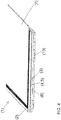
- the inner side of the multilayer film additionally has a layer as a flexible inflatable air chamber, which can be inflated via compressed air in a set shielding position.
- the inflatable air chambers can be self-inflating or inflatable using compressed air.
- the inflation takes place by means of Compressed air.
- the air When rolling up, the air preferably escapes automatically, so that no further steps need to be taken. This allows the film to be wound up and unwound quickly.
- a shaping material is arranged in the interior of the air chambers, which material keeps the air chambers in the filled position in the unwound state.
- the air chambers are used for thermal insulation.
- the film can preferably be clamped pneumatically or hydraulically.
- One advantage is that these systems are regularly available on a ship.
- the film which is under tension due to such a system, can absorb pressure surges which occur, for example, from gusts or water hammer.
- the film can yield under a load that is above the force of the clamping and thus avoid the enormous loads.
- the multilayer film can be stretched in the area in the x and y directions.
- Sufficient stability for the film can be achieved by bracing in the x and y directions, that is to say in the horizontal and vertical directions. This is particularly important if, for example, the film can be exposed to the force of waves during high seas.
- the film is in an orientation that deviates from the vertical tense.
- the film preferably has the same orientation that deviates from the vertical as the surrounding ship wall.
- Ship walls are usually inclined at an angle of 10 ° to 25 °, for example 15 °, in order to reflect radar beams away from the transmitter and thus reduce the radar cross section (RCS).
- the multilayer film 1 shown consists of an outer layer 7, which is designed according to a color specification of the ship and serves as UV protection. This is followed by a layer 2 reflecting radar beams. These layers 7, 2 are on a multilayer laminate with its Layers 3 to 6 are attached and are similar to the construction of a modern, laminated, high-performance sail to meet the requirements of wind and sea blows.
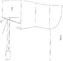
- the multilayer film 1 is according to Fig. 3 arranged on the ship deck between a container 12 and the ship structure.
- fastening rails for example, are arranged on the container 12, into which a piping 9 on the top of the film 1 can be inserted.
- Fig. 2 The film 1 has an inserted stabilizing rail 10 and reinforced open sides 11.
- attachment points 8 are arranged which can be connected to the ship on the deck side in order to set a smooth and stable surface of the surface of the film 1.
- the inside of the film 1 is also provided to provide a layer 13 as an inflatable air chamber. This makes an integrated insulating layer possible.
- the film 1 When using film 1 as a roller door, it is advisable to carry out guidance on all sides.
- the film 1 is connected in the upper region by an unwinding device 15 provided with a drive 14 and the film 1 is guided by lateral guide rails 16 and fixed in the closed position via a lower rail 17.
- a moveable guide rail 16 enables the film to be tightened in the x direction.
- a fixation of the lower rail 17, coupled with an opposite movement of the roller device, enables the film to be tightened in the y direction. Both movements reduce a curvature of the film under load, which would have a negative effect on the reduction of the radar reflection.
- the air When using a film 1 with a layer 13 as an inflatable air chamber, the air is only filled in in the closed position and removed again for opening.
Landscapes
- Engineering & Computer Science (AREA)
- Aviation & Aerospace Engineering (AREA)
- General Engineering & Computer Science (AREA)
- Laminated Bodies (AREA)
- Details Of Aerials (AREA)
Description
- Die Erfindung bezieht sich auf ein Marineschiff mit deckseitigen Abdeckungen für Zugangsöffnungen zur Reduktion der Radarsignatur (RCS, Radar-Cross-Section, Radarquerschnitt) in Form von Folien, wobei die Folien durch einen Werkstoff aus Radarstrahlen refektierendem Materialgebildet sind.
- Für die Reduktion der Radarsignatur von Marineschiffen ist ein erheblicher Aufwand erforderlich. Hierzu werden Flächen des Rumpfes und der Aufbauten oberhalb der Wasserlinie geneigt und rechte Winkel sowie Rundungen vermieden. Es werden daher Ausrüstungsgegenstände unter Deck verlegt. Bei einigen Geräten, Systemen oder Missionsmodulen ist eine derartige Änderung der äußeren Geometrie nicht möglich. Auch eine zunehmende Verwendung von Containern an Deck für verschiedene Aufgaben eines Marineschiffes erhöhen die RCS-Werte eines Schiffes erheblich und heben den Effekt einer optimierten Schiffsstruktur teilweise wieder auf.
- Es ist bereits nach der
DE 102 56 984 B4 eine Anordnung über eine Abdeckeinrichtung bekannt, eine negativ auswirkende Erhöhung einer Radarsignatur zu verhindern. Ferner ist nachDE 10 2005 004 682 A1 eine Tarneinrichtung für Schiffe zur Vermeidung einer Radarrückstrahlung bekannt geworden. Auch nach derDE 10 2006 060 468 B3 ist ein deckseitig angeordneter Behälter bekannt geworden, der geneigte Außenwände zur Vermeidung einer Radarreflexion aufweist. - Der
US 4,495,239 ist eine Tarnfolie bekannt. Ebenso aus derDE 1 227 090 A , derDE 88 13 680 U1 und derDE 10 2004 025 647 A1 sind weitere Tarnvorrichtungen bekannt. DerJP 2002 068 082 A - Aus der
US 33 49 397 A ist ein flexibler Radarabschwächer mit einer flexiblen leitfähigen Schicht bekannt. - Aus der
US 6 444 595 B1 ist eine Beschichtung zur Verhinderung von Korrosion von metallischen Objekten bekannt. Aus derUS 2003/220041 A1 ist ein schützender Überzug bekannt. - Aus der
US 3 047 860 A ist ein Reflektor für elektromagnetische Strahlung bekannt. - Aus der
US 5 077 556 A Abdeckhaube zur Verschleierung von Objekten bekannt. - Aus der
US 5 164 242 A ist eine elektromagnetische Wellen abschwächende Struktur bekannt. - Aus der
WO 2007/142125 A1 ist eine Plane zur Abschirmung von Radiowellen bekannt. - Aus der
US 2012/0147582 A1 ist eine aufrollbare Abschirmvorrichtung bekannt. - Aus der
US 5,436,630 A ist ein Radarschild bekannt. - Aus der
DE 89 10 698 U1 ist eine Abdeckvorrichtung für eine Öffnung mit einem elektrischen Abschirmmaterial bekannt. - Aus der
US 2014/008118 A1 ist eine Abschirmvorrichtung bekannt. - Die Aufgabe der Erfindung ist es, eine Ausbildung für eine deckseitige Abdeckung zur Reduktion der Radarsignatur auf Marineschiffen zu schaffen, die ein geringes Gewicht aufweist sowie eine leichte Handhabung ermöglicht und eine hohe Flexibilität zum Abdecken gewährleistet sowie dabei eine ähnlich hohe mechanische Schutzfunktion gegen Seeschlag und Winddruck ausübt, wie sie von festen Aufbauten auf Seeschiffen gefordert wird.
- Die Lösung dieser Aufgabe erfolgt erfindungsgemäß dadurch, dass die Folie mehrlagig ausgebildet ist und mindestens durch eine außenliegende Decklage zur farblichen Anpassung, als Radar reflektierenden Fläche sowie ein mehrlagiges Laminat als Schutzlage vor Wind und Seeschlag gebildet ist und dass die mehrlagige Folie über Halterungen in einer Abschirmposition einspannbar ist. Diese Folie dient für Zugangsöffnungen zur Reduktion von Radarsignaturen auf einem Marineschiff. Die Folie ist mehrlagig ausgebildet und ist mindestens durch eine außenliegende Decklage zur farblichen Anpassung, eine Metalllage als Radar reflektierende Fläche sowie ein mehrlagiges Laminat als Schutzlage vor Wind und Seeschlag gebildet. Die mehrlagige Folie ist über Halterungen in einer Abschirmposition einspannbar, wobei die Aufwickelvorrichtung ein tragendes Seil oder einen Draht aufweist, wobei die Folie auf ein das Seil oder den Draht umschließendes Hohlprofil aufgewickelt wird.
- Unter einer Metalllage wird im Sinne der Erfindung jede elektrisch leitfähige Lage verstanden. Als leitfähig werden insbesondere Materialien mit einer Leitfähigkeit von wenigstens 10-3 S/m verstanden. Insbesondere umfasst eine Metalllage eine flächige Metallschicht, ein Gewebe, ein Gitter oder ein Geflecht aus leitfähigen Fasern, eine statistische Verteilung von leitfähigen Fasern, wobei die Fasern leitfähige Verbindungen aufweisen. Insbesondere umfasst die Metallschicht ein Metallmesh, eine Carbonschicht und eine Schicht Kohlenstoffnanoröhren enthaltend.
- Hierdurch ist es möglich, auf einfache Weise eine funktionsfähige handhabende Ausbildung zum Abdecken bzw. Verschließen von deckseitigen Anordnungen durchzuführen.
- In einer bevorzugten Ausführungsform der Erfindung handelt es sich bei Folie um ein Laminat aus einem Basismaterial, einer Metallfolie und einer außenliegenden Decklage, beispielsweise einer UV-Schutzfolie, wobei eine außenliegende Decklage, beispielswiese die UV-Schutzfolie, vorzugsweise farblich an das Schiff angepasst ist. Durch die Lamination zu einer Folie wird eine besonders innige Verbindung zwischen den Komponenten geschaffen, wodurch die für die Anwendung auf See notwendige Stabilität erreicht wird.
- In einer besonders bevorzugten Ausführungsform handelt es sich bei dem Basismaterial um eine Folie mit Kunstfaserverstärkung, besonders bevorzugt um eine ThinPreg 120EP der Firma North Thin Ply Technology SÄRL.
- In einer weiteren Ausführungsform handelt es sich bei der Folie um ein Laminat aus einer Basisfolie, mehreren lastaufnehmenden Folien mit Faserverstärkung, einem Metallgewebe und einer UV-Schutzfolie, wobei die UV-Schutzfolie vorzugsweise farblich an das Schiff angepasst ist. Vorteil der Verwendung eines Metallgewebes ist die gute und stabile Verbindung des Basismaterials mit der UV-Schutzfolie. Metall stellt regelmäßig in einem Laminat eine Trennschicht dar, was durch die in einem Gewebe vorhandenen Zwischenräume vermieden werden kann. Besonders bevorzugt ist die Ausführung mit einem Metallgewebe als Prepreg, wie sie beispielsweise von Mitsubishi Rayon als PYROFIL angeboten wird.
- Zur Herstellung des Laminats kann zwischen den Folien ein Kleber verwendet werden. Besonders bevorzugt ist die Verwendung eines Klebers bei der Verwendung eines Metallgewebes, da der Kleber das Metallgewebe in flüssiger Form besonders gut durchdringen kann und so die notwendigen Temperaturen und Zeiten bei der Herstellung des Laminats verringert werden können.
- In einer weiteren Ausführungsform werden das Basismaterial und die UV-Schutzfolie mit Hilfe eines Metall enthaltenden Klebers laminiert. Der metallhaltige Kleber kann vorzugsweise drucktechnisch auf das Basismaterial und/oder die UV-Schutzfolie aufgebracht werden. Vorzugsweise weist der Metall enthaltende Kleber wenigstens 60 Gew.-% Metall auf. Beispielsweise können handelsübliche Silberleitkleber auf Epoxyd-Basis verwendet werden. Silber weist auch in dieser Form eine extrem hohe Leitfähigkeit und somit gute Reflexionseigenschaften auf.
- Vorzugsweise erfolgt die Lamination bei 60 °C bis 250 °C, weiter bevorzugt bei 80 °C bis 210 °C, besonders bevorzugt bei 140 °C bis 180 °C, beispielsweise bei 160 °C. Besonders bevorzugt erfolgt die Lamination unter Vakuum.
- Bevorzugt werden für das Laminat der lasttragenden Lagen extrem dünne und leichte Faserverstärkungen verwendet. Besonders bevorzugt werden unidirektionale Faserverstärkungen mit einer Schichtdicke von unter 50 µm und einem Flächengewicht von unter 100 g/m2 verwendet. Diese werden besonders bevorzugt entsprechend der Lasten auf der Folie angeordnet werden, sodass die Faserrichtung in Richtung der zu erwartenden auftretenden Kräfte angeordnet sind.
- Um eine Verspannung der Folie in der Abschirmposition und zur Isolierung, insbesondere von Zugangsöffnungen zu schaffen, wird vorgeschlagen, dass die mehrlagige Folie mindestens einseitig über eine Aufwickelvorrichtung angeordnet und über Führungselemente positionierbar in der Abschirmposition gehalten ist.
- Für eine Verwendung in einer Aufwickelvorrichtung ist die Verwendung eines Laminats sehr bevorzugt, da dieses durch die innige Verbindung der Komponenten sehr leicht rollbar ist. Auch wird durch das Vermeiden von weiteren Arbeitsschritten, beispielsweise des nach dem Ausrollen ein Einfügen von Radarabsorbierenden oder reflektierenden Materialien notwendig wäre, die Zeit zum Öffnen und Schließen deutlich verkürzt.
- Erfindungsgemäß weist die Aufwickelvorrichtung ein tragendes Seil oder einen Draht auf, wobei die Folie auf ein das Seil oder den Draht umschließendes Hohlprofil aufgewickelt wird. Vorteil dieser Ausführungsform ist es, dass das vergleichsweise hohe Gewicht eines Rohres vermieden werden kann. Hinzu kommt, dass bei Verwendung eines Rohres als tragendes Element dieses nur schwer gegen die auftretenden hohen Beschleunigungen (Schock) geschützt werden kann. Ein unter Zug stehendes Seil ist hingegen gegen Schockeinwirkung schützbar. Hinzu kommt die massive Gewichtsersparnis, welche sich bei der Verwendung eines Seils oder eines Drahtes gegenüber einem Rohr ergibt. Ein weiterer Vorteil ist die mögliche Verwendung einer Spannvorrichtung, welche eine Durchbiegung der Rolleinrichtung zuverlässig verhindert.
- Erfindungsgemäß bildet die Folie mit der Aufwickelvorrichtung ein Rolltor.
- Ferner wird vorgeschlagen, dass die innenliegende Seite der mehrlagigen Folie zusätzlich eine Lage als flexible aufblasbare Luftkammer aufweist, die über Druckluft in einer eingestellten Abschirmposition aufblasbar ist.
- Die aufblasbaren Luftkammern können selbstaufblasend oder mittels Druckluft aufblasbar ausgeführt sein. In einer bevorzugten Ausführungsform erfolgt das Aufblasen mittels Druckluft. Das bedeutet, dass die Luftkammern eine Verbindung zu einem druckluftbetriebenen System aufweisen. Beim Aufrollen entweicht die Luft vorzugsweise automatisch, sodass keine weiteren Schritte vorzunehmen sind. Dadurch kann die Folie schnell auf- und abgewickelt werden. In der selbstaufblasenden Ausführungsform ist im Inneren der Luftammern ein formgebendes Material angeordnet, welches im abgewickelten Zustand die Luftkammern in der gefüllten Position hält.
- Die Luftkammern dienen der thermischen Isolation.
- Die Einspannung der Folie kann vorzugsweise pneumatisch oder hydraulisch erfolgen. Vorteil ist zum einen, dass diese Systeme auf einem Schiff regelmäßig zur Verfügung stehen. Zum anderen kann die Folie, welche durch ein solches System unter Spannung steht, bei Druckstöße, welche beispielsweise durch Böen oder Wasserschlag auftreten, abfedern. Die Folie kann bei einer Belastung, welche oberhalb der Kraft der Einspannung liegt, nachgeben und so den enormen Belastungen ausweichen.
- In einer weiteren Ausführungsform der Erfindung ist die mehrlagige Folie in x- sowie y-Richtung in der Fläche spannbar. Durch eine Verspannung in x- sowie y-Richtung, also in horizontaler und vertikaler Richtung, kann eine ausreichende Stabilität für die Folie erreicht werden. Dieses ist insbesondere wichtig, wenn die Folie beispielsweise der Kraft von Wellen bei hohem Seegang ausgesetzt sein kann.
- In einer weiteren Ausführungsform der Erfindung ist die Folie in einer von der Senkrechten abweichenden Orientierung verspannt. Vorzugsweise weist die Folie die gleiche von der Senkrechten abweichenden Orientierung wie die umgebende Schiffswand auf. Schiffwände sind üblicherweise in einem Winkel von 10 ° bis 25 °, beispielsweise 15 ° geneigt, um Radarstrahlen vom Sender weg zu reflektieren und so den Radarquerschnitt (RCS) zu verringern.
- In der Zeichnung sind Ausführungsbeispiele der Erfindung schematisch dargestellt.
- Es zeigen:
- Fig. 1
- eine Darstellung eine mehrlagige Folie,
- Fig. 2
- eine Draufsicht auf eine Folie,
- Fig. 3
- eine Seitenansicht einer an einem Container angeordneten Folie,
- Fig. 4
- eine Darstellung einer mehrlagigen Folie mit einer zusätzlichen Lage als flexible aufblasbare Luftkammer und
- Fig. 5
- eine positionierte Folie als Rolltor mit einer Aufwickelvorrichtung und Halterung über Führungselemente.
- Die dargestellte mehrlagige Folie 1 besteht aus einer äußeren Lage 7, die entsprechend einer farblichen Vorgabe des Schiffes ausgebildet wird und als UV-Schutz dient. Anschließend folgt eine Radarstrahlen reflektierende Lage 2. Diese Lagen 7, 2 sind auf ein mehrlagiges Laminat mit seinen Schichten 3 bis 6 angebracht und ähneln dem Aufbau eines modernen laminierten Hochleistungssegels , um den Anforderungen von Wind- und Seeschlag zu erfüllen.
- Die mehrlagige Folie 1 ist dabei gemäß
Fig. 3 auf dem Schiffsdeck zwischen einem Container 12 und der Schiffsstruktur angeordnet. Hierzu sind beispielsweise Befestigungsschienen am Container 12 angeordnet, in die ein Keder 9 an der Oberseite der Folie 1 einsetzbar ist. GemäßFig. 2 besitzt die Folie 1 eine eingesetzte Stabilisierungsschiene 10 und verstärkte offene Seiten 11. Im unteren Bereich der Fläche 1 sind Anschlagspunkte 8 angeordnet, die deckseitig mit dem Schiff verbindbar sind, um eine glatte und stabile Fläche der Oberfläche der Folie 1 einzustellen. - Zur Anpassung für die Radar reflektierende Lage 2 sind unterschiedliche Materialien vorgesehen, die die Charakteristik der Radarrückstrahlung des jeweiligen Schiffbaumaterials - Stahl, Aluminium, Karbon, Kunststoff - nachbilden. Mögliche Materialien für die Radar reflektierende Lage 2 sind:
- Aluminiumfolie (bei Stahl- oder Aluminiumaufbauten)
- Aluminium Gaze (bei Stahl- oder Aluminiumaufbauten)
- Nirofolie (bei Stahl- oder Aluminiumaufbauten)
- Niro Gaze (bei Stahl- oder Aluminiumaufbauten)
- Kohlefaser (bei Kohlefaseraufbauten)
- Dyneema ® oder ähnliche Kunstfaser (bei Kunststoffaufbauten)
- Bei einer Verwendung der mehrlagigen Folie 1 für ein Rolltor ist vorgesehen, die Innenseite der Folie 1 zusätzlich mit einer Lage 13 als aufblasbare Luftkammer zu versehen. Hierdurch ist eine integrierte Isolierschicht möglich.
- Bei Verwendung der Folie 1 als Rolltor ist es zweckdienlich, eine Führung an allen Seiten vorzunehmen. Hierzu wird die Folie 1 durch eine mit einem Antrieb 14 versehenen Abwickelvorrichtung 15 im oberen Bereich verbunden und die Folie 1 durch seitliche Führungsschiene 16 geführt und in der Schließposition über eine untere Schiene 17 festgelegt. Durch eine bewegliche Führungsschiene 16 wird eine Straffung der Folie in x-Richtung ermöglicht. Eine Fixierung der unteren Schiene 17, gekoppelt mit einer gegenläufigen Bewegung der Rolleinrichtung, ermöglicht eine Straffung der Folie in y-Richtung. Beide Bewegungen vermindern eine Wölbung der Folie unter Last welche sich negativ auf die Reduktion der Radarrückstrahlung auswirken würde. Bei Verwendung einer Folie 1 mit einer Lage 13 als aufblasbare Luftkammer wird die Luft erst in der Schließposition eingefüllt und zum Öffnen wieder entfernt.
Claims (9)
- Marineschiff mit deckseitigen Abdeckungen für Zugangsöffnungen zur Reduktion von Radarsignaturen in Form von Folien, wobei das Marineschiff ein Rolltor aufweist, wobei das Rolltor eine Folie (1) und eine Aufwickelvorrichtung (14, 15) aufweist, wobei die Folien durch einen Werkstoff aus RCS-Material (Radar-Cross-Section) gebildet sind, wobei die Folie (1) mehrlagig ausgebildet ist und mindestens durch eine außenliegende Decklage (7) zur farblichen Anpassung, eine Metalllage (2) als Radar reflektierende Fläche sowie ein mehrlagiges Laminat (3-6) als Schutzlage vor Wind und Seeschlag gebildet ist und dass die mehrlagige Folie (1) über Halterungen (8, 9) in einer Abschirmposition einspannbar ist, wobei die Aufwickelvorrichtung ein tragendes Seil oder einen Draht aufweist, wobei die Folie auf ein das Seil oder den Draht umschließendes Hohlprofil aufgewickelt wird.
- Marineschiff nach Anspruch 1, dadurch gekennzeichnet, dass die Folie in einer von der Senkrechten abweichenden Orientierung verspannt ist.
- Marineschiff nach Anspruch 2, dadurch gekennzeichnet, dass die Folie die gleiche von der Senkrechten abweichenden Orientierung wie die umgebende Schiffswand aufweist.
- Marineschiff nach einem der vorangegangenen Ansprüche, dadurch gekennzeichnet, dass die mehrlagige Folie in x-sowie y-Richtung in der Fläche spannbar ist.
- Marineschiff nach einem der vorangegangenen Ansprüche, dadurch gekennzeichnet, dass es sich bei der Folie um ein Laminat aus einer Basisfolie, mehreren lastaufnehmenden Folien mit Faserverstärkung, einem Metallgewebe und einer UV-Schutzfolie handelt.
- Marineschiff nach einem der vorangegangenen Ansprüche, dadurch gekennzeichnet, dass die mehrlagige Folie mindestens einseitig über eine Aufwickelvorrichtung (14, 15) angeordnet, über Führungselemente (16, 17) positionierbar in der Abschirmposition gehalten ist.
- Marineschiff nach einem der vorangegangenen Ansprüche, dadurch gekennzeichnet, dass die mehrlagige Folie in x-sowie y-Richtung in der Fläche spannbar ist.
- Marineschiff nach einem der vorangegangenen Ansprüche, dadurch gekennzeichnet, dass die innenliegende Seite der mehrlagigen Folie (1) zusätzlich eine Lage als flexible aufblasbare Luftkammer (13) aufweist, die über Druckluft in einer eingestellten Abschirmposition als thermische Isolation aufblasbar ist.
- Marineschiff nach einem der vorangegangenen Ansprüche, dadurch gekennzeichnet, dass die Folie in einer von der Senkrechten abweichenden Orientierung verspannt ist.
Applications Claiming Priority (2)
| Application Number | Priority Date | Filing Date | Title |
|---|---|---|---|
| DE102014003129.2A DE102014003129A1 (de) | 2014-03-04 | 2014-03-04 | Marineschiff mit deckseitigen Abdeckungen zur Reduzierung von Radarsignaturen |
| PCT/EP2015/054512 WO2015132301A1 (de) | 2014-03-04 | 2015-03-04 | Marineschiff mit deckseitigen abdeckungen zur reduzierung von radarsignaturen |
Publications (2)
| Publication Number | Publication Date |
|---|---|
| EP3114028A1 EP3114028A1 (de) | 2017-01-11 |
| EP3114028B1 true EP3114028B1 (de) | 2020-04-29 |
Family
ID=52629568
Family Applications (1)
| Application Number | Title | Priority Date | Filing Date |
|---|---|---|---|
| EP15708193.6A Active EP3114028B1 (de) | 2014-03-04 | 2015-03-04 | Marineschiff mit deckseitigen abdeckungen zur reduzierung von radarsignaturen |
Country Status (4)
| Country | Link |
|---|---|
| EP (1) | EP3114028B1 (de) |
| DE (1) | DE102014003129A1 (de) |
| ES (1) | ES2791880T3 (de) |
| WO (1) | WO2015132301A1 (de) |
Families Citing this family (3)
| Publication number | Priority date | Publication date | Assignee | Title |
|---|---|---|---|---|
| CA3039666C (en) | 2016-10-28 | 2022-08-23 | Ppg Industries Ohio, Inc. | Coatings for increasing near-infrared detection distances |
| ES3026908T3 (en) | 2018-11-13 | 2025-06-12 | Ppg Ind Ohio Inc | Method of detecting a concealed pattern |
| US11561329B2 (en) | 2019-01-07 | 2023-01-24 | Ppg Industries Ohio, Inc. | Near infrared control coating, articles formed therefrom, and methods of making the same |
Citations (5)
| Publication number | Priority date | Publication date | Assignee | Title |
|---|---|---|---|---|
| DE8910698U1 (de) * | 1988-09-17 | 1990-01-11 | Kitagawa Industries Co., Ltd., Nagoya, Aichi | Abdeckvorrichtung für eine Öffnung zum Abschirmen von elektromagnetischer Strahlung |
| US5436630A (en) * | 1989-05-25 | 1995-07-25 | British Aerospace Plc | Radar shields |
| WO2007142125A1 (ja) * | 2006-06-02 | 2007-12-13 | Mitsubishi Cable Industries, Ltd. | 電波遮蔽性仕切面材およびその製造方法 |
| US20120147582A1 (en) * | 2010-12-09 | 2012-06-14 | Hon Hai Precision Industry Co., Ltd. | Emi shield apparatus and electronic device with same |
| US20140008118A1 (en) * | 2012-07-06 | 2014-01-09 | Hon Hai Precision Industry Co., Ltd. | Shielding apparatus and cabinet with same |
Family Cites Families (13)
| Publication number | Priority date | Publication date | Assignee | Title |
|---|---|---|---|---|
| US3047860A (en) * | 1957-11-27 | 1962-07-31 | Austin B Swallow | Two ply electromagnetic energy reflecting fabric |
| DE1227090B (de) * | 1964-06-01 | 1966-10-20 | Klaus Krasselt | Anordnung zum Unerfassbarmachen von Gegenstaenden fuer Radarstrahlen |
| US3349397A (en) * | 1966-02-03 | 1967-10-24 | North American Aviation Inc | Flexible radiation attenuator |
| DE2750919C1 (de) * | 1977-11-15 | 1984-03-01 | Pusch, Günter, Dr.-Ing., 6903 Neckargemünd | Breitbandige Tarnung militaerischer Ziele |
| DE8813680U1 (de) * | 1988-11-02 | 1989-05-03 | Spinnerei und Webereien Zell-Schönau AG, 7863 Zell | Plane zur Abschirmung von Objekten |
| DE69024796T2 (de) * | 1990-02-06 | 1996-05-30 | Bell Helicopter Textron Inc | Struktur für elektromagnetische wellenverminderung und enteisung |
| US6794317B2 (en) * | 2000-04-26 | 2004-09-21 | Creare Inc. | Protective cover system including a corrosion inhibitor |
| US6444595B1 (en) * | 2000-04-26 | 2002-09-03 | Creare Inc. | Flexible corrosion-inhibiting cover for a metallic object |
| JP2002068082A (ja) * | 2000-08-30 | 2002-03-08 | Kayaba Ind Co Ltd | ステルスカーテン |
| DE10256984B4 (de) | 2002-12-05 | 2005-08-11 | Buck Neue Technologien Gmbh | Radar-getarnter Werfer |
| DE102004025647B4 (de) * | 2004-05-26 | 2008-03-27 | Eads Deutschland Gmbh | Einrichtung zum Tarnen spekular reflektierender Oberflächen |
| DE102005004682A1 (de) | 2005-02-02 | 2006-08-17 | Blohm + Voss Gmbh | Schiff mit Tarneinrichtung |
| DE102006060468C5 (de) | 2006-12-19 | 2010-05-27 | Kaefer Isoliertechnik Gmbh & Co. Kg | Behälter auf militärischen Schiffen |
-
2014
- 2014-03-04 DE DE102014003129.2A patent/DE102014003129A1/de not_active Withdrawn
-
2015
- 2015-03-04 EP EP15708193.6A patent/EP3114028B1/de active Active
- 2015-03-04 ES ES15708193T patent/ES2791880T3/es active Active
- 2015-03-04 WO PCT/EP2015/054512 patent/WO2015132301A1/de not_active Ceased
Patent Citations (5)
| Publication number | Priority date | Publication date | Assignee | Title |
|---|---|---|---|---|
| DE8910698U1 (de) * | 1988-09-17 | 1990-01-11 | Kitagawa Industries Co., Ltd., Nagoya, Aichi | Abdeckvorrichtung für eine Öffnung zum Abschirmen von elektromagnetischer Strahlung |
| US5436630A (en) * | 1989-05-25 | 1995-07-25 | British Aerospace Plc | Radar shields |
| WO2007142125A1 (ja) * | 2006-06-02 | 2007-12-13 | Mitsubishi Cable Industries, Ltd. | 電波遮蔽性仕切面材およびその製造方法 |
| US20120147582A1 (en) * | 2010-12-09 | 2012-06-14 | Hon Hai Precision Industry Co., Ltd. | Emi shield apparatus and electronic device with same |
| US20140008118A1 (en) * | 2012-07-06 | 2014-01-09 | Hon Hai Precision Industry Co., Ltd. | Shielding apparatus and cabinet with same |
Also Published As
| Publication number | Publication date |
|---|---|
| EP3114028A1 (de) | 2017-01-11 |
| DE102014003129A1 (de) | 2015-09-10 |
| WO2015132301A1 (de) | 2015-09-11 |
| ES2791880T3 (es) | 2020-11-06 |
Similar Documents
| Publication | Publication Date | Title |
|---|---|---|
| EP2445788B1 (de) | Hubschrauber mit einer Lasthebevorrichtung | |
| DE102010052671B4 (de) | Isolierungsanordnung mit Ventilationsöffnungen für Luftfahrzeuge | |
| EP2386691A1 (de) | Vorrichtung und Verfahren für den Kolkschutz von Offshore- Bauwerken | |
| DE102012202132B4 (de) | Verfahren und Vorrichtung zum Schallschutz | |
| DE1299404B (de) | Vorrichtung zum Schutz vor Stosswellen | |
| DE69402328T2 (de) | Drahtschneidegerät mit aerodynamischer und energieabsorbierender bugverkleidung | |
| WO2012113885A1 (de) | Allseits verschliessbarer seecontainer | |
| WO2015132301A1 (de) | Marineschiff mit deckseitigen abdeckungen zur reduzierung von radarsignaturen | |
| DE102010046608B4 (de) | Vorrichtung zum Verschließen einer seitlichen Öffnung in der Außenhaut oder Wandung eines Boots | |
| DE202019103668U1 (de) | Schallabschirmungsmatte, Schallabschirmungssystem und Gleisoberbaumaschine | |
| DE102021106321A1 (de) | Antennenverkleidung für Flugzeuge | |
| DE102009046257A1 (de) | Plattenförmige Isolationslage für eine Wand, Verfahren zu deren Herstellung sowie plattenförmiges Wandelement | |
| DE202021101912U1 (de) | Mobile Schutzvorrichtung zum Abdichten von Gebäuden gegen Hochwasser | |
| DE102012209082A1 (de) | Ausfahrgerät für ein Unterseeboot | |
| WO2024250061A1 (en) | A method for enhancing the physical properties of objects or devices | |
| EP1783047B1 (de) | Unterseeboot mit einer Schleppleine | |
| EP3492145A1 (de) | Personenrettungssystem und verfahren zur evakuierung von personen aus einem bauwerk | |
| WO2004076853A1 (de) | Offshore-windenergieanlage | |
| DE202009011263U1 (de) | Vorrichtung zum Schutz eines Schiffsrumpfes gegen Einflüsse von Schockwellen | |
| DE102016008025A1 (de) | Schutzhelm mit Versteifungsvorrichtung | |
| DE69927984T2 (de) | Notsauerstoffversorgungsanlage für flugzeugpassagiere | |
| EP3725663A1 (de) | Lukendeckel und verfahren zur konfiguration eines lukendeckels | |
| DE202009010591U1 (de) | Thermisch wirksames Fassadenelement für Gebäudewände sowie System zur thermischen Isolierung einer Gebäudewand | |
| EP3477019A1 (de) | In der dachkonstruktion wärmebrückenfrei fixierter pfosten für absturzsicherungen oder absturzsicherungssysteme | |
| EP1099623B1 (de) | Aufblasbare Trennwand zur Reduzierung freier Oberflächen |
Legal Events
| Date | Code | Title | Description |
|---|---|---|---|
| STAA | Information on the status of an ep patent application or granted ep patent |
Free format text: STATUS: THE INTERNATIONAL PUBLICATION HAS BEEN MADE |
|
| PUAI | Public reference made under article 153(3) epc to a published international application that has entered the european phase |
Free format text: ORIGINAL CODE: 0009012 |
|
| STAA | Information on the status of an ep patent application or granted ep patent |
Free format text: STATUS: REQUEST FOR EXAMINATION WAS MADE |
|
| 17P | Request for examination filed |
Effective date: 20160819 |
|
| AK | Designated contracting states |
Kind code of ref document: A1 Designated state(s): AL AT BE BG CH CY CZ DE DK EE ES FI FR GB GR HR HU IE IS IT LI LT LU LV MC MK MT NL NO PL PT RO RS SE SI SK SM TR |
|
| AX | Request for extension of the european patent |
Extension state: BA ME |
|
| DAV | Request for validation of the european patent (deleted) | ||
| DAX | Request for extension of the european patent (deleted) | ||
| STAA | Information on the status of an ep patent application or granted ep patent |
Free format text: STATUS: EXAMINATION IS IN PROGRESS |
|
| 17Q | First examination report despatched |
Effective date: 20180416 |
|
| RAP1 | Party data changed (applicant data changed or rights of an application transferred) |
Owner name: THYSSENKRUPP MARINE SYSTEMS GMBH |
|
| GRAP | Despatch of communication of intention to grant a patent |
Free format text: ORIGINAL CODE: EPIDOSNIGR1 |
|
| STAA | Information on the status of an ep patent application or granted ep patent |
Free format text: STATUS: GRANT OF PATENT IS INTENDED |
|
| INTG | Intention to grant announced |
Effective date: 20191209 |
|
| GRAS | Grant fee paid |
Free format text: ORIGINAL CODE: EPIDOSNIGR3 |
|
| GRAA | (expected) grant |
Free format text: ORIGINAL CODE: 0009210 |
|
| STAA | Information on the status of an ep patent application or granted ep patent |
Free format text: STATUS: THE PATENT HAS BEEN GRANTED |
|
| AK | Designated contracting states |
Kind code of ref document: B1 Designated state(s): AL AT BE BG CH CY CZ DE DK EE ES FI FR GB GR HR HU IE IS IT LI LT LU LV MC MK MT NL NO PL PT RO RS SE SI SK SM TR |
|
| REG | Reference to a national code |
Ref country code: GB Ref legal event code: FG4D Free format text: NOT ENGLISH |
|
| REG | Reference to a national code |
Ref country code: CH Ref legal event code: EP |
|
| REG | Reference to a national code |
Ref country code: DE Ref legal event code: R084 Ref document number: 502015012422 Country of ref document: DE |
|
| REG | Reference to a national code |
Ref country code: AT Ref legal event code: REF Ref document number: 1262925 Country of ref document: AT Kind code of ref document: T Effective date: 20200515 |
|
| REG | Reference to a national code |
Ref country code: DE Ref legal event code: R096 Ref document number: 502015012422 Country of ref document: DE |
|
| REG | Reference to a national code |
Ref country code: IE Ref legal event code: FG4D Free format text: LANGUAGE OF EP DOCUMENT: GERMAN |
|
| REG | Reference to a national code |
Ref country code: NL Ref legal event code: FP |
|
| REG | Reference to a national code |
Ref country code: LT Ref legal event code: MG4D |
|
| PG25 | Lapsed in a contracting state [announced via postgrant information from national office to epo] |
Ref country code: SE Free format text: LAPSE BECAUSE OF FAILURE TO SUBMIT A TRANSLATION OF THE DESCRIPTION OR TO PAY THE FEE WITHIN THE PRESCRIBED TIME-LIMIT Effective date: 20200429 Ref country code: LT Free format text: LAPSE BECAUSE OF FAILURE TO SUBMIT A TRANSLATION OF THE DESCRIPTION OR TO PAY THE FEE WITHIN THE PRESCRIBED TIME-LIMIT Effective date: 20200429 Ref country code: FI Free format text: LAPSE BECAUSE OF FAILURE TO SUBMIT A TRANSLATION OF THE DESCRIPTION OR TO PAY THE FEE WITHIN THE PRESCRIBED TIME-LIMIT Effective date: 20200429 Ref country code: NO Free format text: LAPSE BECAUSE OF FAILURE TO SUBMIT A TRANSLATION OF THE DESCRIPTION OR TO PAY THE FEE WITHIN THE PRESCRIBED TIME-LIMIT Effective date: 20200729 Ref country code: PT Free format text: LAPSE BECAUSE OF FAILURE TO SUBMIT A TRANSLATION OF THE DESCRIPTION OR TO PAY THE FEE WITHIN THE PRESCRIBED TIME-LIMIT Effective date: 20200831 Ref country code: IS Free format text: LAPSE BECAUSE OF FAILURE TO SUBMIT A TRANSLATION OF THE DESCRIPTION OR TO PAY THE FEE WITHIN THE PRESCRIBED TIME-LIMIT Effective date: 20200829 Ref country code: GR Free format text: LAPSE BECAUSE OF FAILURE TO SUBMIT A TRANSLATION OF THE DESCRIPTION OR TO PAY THE FEE WITHIN THE PRESCRIBED TIME-LIMIT Effective date: 20200730 |
|
| REG | Reference to a national code |
Ref country code: ES Ref legal event code: FG2A Ref document number: 2791880 Country of ref document: ES Kind code of ref document: T3 Effective date: 20201106 |
|
| PG25 | Lapsed in a contracting state [announced via postgrant information from national office to epo] |
Ref country code: LV Free format text: LAPSE BECAUSE OF FAILURE TO SUBMIT A TRANSLATION OF THE DESCRIPTION OR TO PAY THE FEE WITHIN THE PRESCRIBED TIME-LIMIT Effective date: 20200429 Ref country code: HR Free format text: LAPSE BECAUSE OF FAILURE TO SUBMIT A TRANSLATION OF THE DESCRIPTION OR TO PAY THE FEE WITHIN THE PRESCRIBED TIME-LIMIT Effective date: 20200429 Ref country code: RS Free format text: LAPSE BECAUSE OF FAILURE TO SUBMIT A TRANSLATION OF THE DESCRIPTION OR TO PAY THE FEE WITHIN THE PRESCRIBED TIME-LIMIT Effective date: 20200429 Ref country code: BG Free format text: LAPSE BECAUSE OF FAILURE TO SUBMIT A TRANSLATION OF THE DESCRIPTION OR TO PAY THE FEE WITHIN THE PRESCRIBED TIME-LIMIT Effective date: 20200729 |
|
| PG25 | Lapsed in a contracting state [announced via postgrant information from national office to epo] |
Ref country code: AL Free format text: LAPSE BECAUSE OF FAILURE TO SUBMIT A TRANSLATION OF THE DESCRIPTION OR TO PAY THE FEE WITHIN THE PRESCRIBED TIME-LIMIT Effective date: 20200429 |
|
| PG25 | Lapsed in a contracting state [announced via postgrant information from national office to epo] |
Ref country code: CZ Free format text: LAPSE BECAUSE OF FAILURE TO SUBMIT A TRANSLATION OF THE DESCRIPTION OR TO PAY THE FEE WITHIN THE PRESCRIBED TIME-LIMIT Effective date: 20200429 Ref country code: RO Free format text: LAPSE BECAUSE OF FAILURE TO SUBMIT A TRANSLATION OF THE DESCRIPTION OR TO PAY THE FEE WITHIN THE PRESCRIBED TIME-LIMIT Effective date: 20200429 Ref country code: EE Free format text: LAPSE BECAUSE OF FAILURE TO SUBMIT A TRANSLATION OF THE DESCRIPTION OR TO PAY THE FEE WITHIN THE PRESCRIBED TIME-LIMIT Effective date: 20200429 Ref country code: DK Free format text: LAPSE BECAUSE OF FAILURE TO SUBMIT A TRANSLATION OF THE DESCRIPTION OR TO PAY THE FEE WITHIN THE PRESCRIBED TIME-LIMIT Effective date: 20200429 Ref country code: SM Free format text: LAPSE BECAUSE OF FAILURE TO SUBMIT A TRANSLATION OF THE DESCRIPTION OR TO PAY THE FEE WITHIN THE PRESCRIBED TIME-LIMIT Effective date: 20200429 |
|
| REG | Reference to a national code |
Ref country code: DE Ref legal event code: R097 Ref document number: 502015012422 Country of ref document: DE |
|
| PG25 | Lapsed in a contracting state [announced via postgrant information from national office to epo] |
Ref country code: SK Free format text: LAPSE BECAUSE OF FAILURE TO SUBMIT A TRANSLATION OF THE DESCRIPTION OR TO PAY THE FEE WITHIN THE PRESCRIBED TIME-LIMIT Effective date: 20200429 Ref country code: PL Free format text: LAPSE BECAUSE OF FAILURE TO SUBMIT A TRANSLATION OF THE DESCRIPTION OR TO PAY THE FEE WITHIN THE PRESCRIBED TIME-LIMIT Effective date: 20200429 |
|
| PLBE | No opposition filed within time limit |
Free format text: ORIGINAL CODE: 0009261 |
|
| STAA | Information on the status of an ep patent application or granted ep patent |
Free format text: STATUS: NO OPPOSITION FILED WITHIN TIME LIMIT |
|
| 26N | No opposition filed |
Effective date: 20210201 |
|
| PG25 | Lapsed in a contracting state [announced via postgrant information from national office to epo] |
Ref country code: SI Free format text: LAPSE BECAUSE OF FAILURE TO SUBMIT A TRANSLATION OF THE DESCRIPTION OR TO PAY THE FEE WITHIN THE PRESCRIBED TIME-LIMIT Effective date: 20200429 |
|
| PG25 | Lapsed in a contracting state [announced via postgrant information from national office to epo] |
Ref country code: MC Free format text: LAPSE BECAUSE OF FAILURE TO SUBMIT A TRANSLATION OF THE DESCRIPTION OR TO PAY THE FEE WITHIN THE PRESCRIBED TIME-LIMIT Effective date: 20200429 |
|
| REG | Reference to a national code |
Ref country code: CH Ref legal event code: PL |
|
| REG | Reference to a national code |
Ref country code: BE Ref legal event code: MM Effective date: 20210331 |
|
| PG25 | Lapsed in a contracting state [announced via postgrant information from national office to epo] |
Ref country code: LI Free format text: LAPSE BECAUSE OF NON-PAYMENT OF DUE FEES Effective date: 20210331 Ref country code: LU Free format text: LAPSE BECAUSE OF NON-PAYMENT OF DUE FEES Effective date: 20210304 Ref country code: CH Free format text: LAPSE BECAUSE OF NON-PAYMENT OF DUE FEES Effective date: 20210331 Ref country code: IE Free format text: LAPSE BECAUSE OF NON-PAYMENT OF DUE FEES Effective date: 20210304 |
|
| REG | Reference to a national code |
Ref country code: AT Ref legal event code: MM01 Ref document number: 1262925 Country of ref document: AT Kind code of ref document: T Effective date: 20210304 |
|
| PG25 | Lapsed in a contracting state [announced via postgrant information from national office to epo] |
Ref country code: BE Free format text: LAPSE BECAUSE OF NON-PAYMENT OF DUE FEES Effective date: 20210331 |
|
| PG25 | Lapsed in a contracting state [announced via postgrant information from national office to epo] |
Ref country code: AT Free format text: LAPSE BECAUSE OF NON-PAYMENT OF DUE FEES Effective date: 20210304 |
|
| PG25 | Lapsed in a contracting state [announced via postgrant information from national office to epo] |
Ref country code: HU Free format text: LAPSE BECAUSE OF FAILURE TO SUBMIT A TRANSLATION OF THE DESCRIPTION OR TO PAY THE FEE WITHIN THE PRESCRIBED TIME-LIMIT; INVALID AB INITIO Effective date: 20150304 |
|
| PG25 | Lapsed in a contracting state [announced via postgrant information from national office to epo] |
Ref country code: CY Free format text: LAPSE BECAUSE OF FAILURE TO SUBMIT A TRANSLATION OF THE DESCRIPTION OR TO PAY THE FEE WITHIN THE PRESCRIBED TIME-LIMIT Effective date: 20200429 |
|
| PG25 | Lapsed in a contracting state [announced via postgrant information from national office to epo] |
Ref country code: MK Free format text: LAPSE BECAUSE OF FAILURE TO SUBMIT A TRANSLATION OF THE DESCRIPTION OR TO PAY THE FEE WITHIN THE PRESCRIBED TIME-LIMIT Effective date: 20200429 |
|
| PG25 | Lapsed in a contracting state [announced via postgrant information from national office to epo] |
Ref country code: MT Free format text: LAPSE BECAUSE OF FAILURE TO SUBMIT A TRANSLATION OF THE DESCRIPTION OR TO PAY THE FEE WITHIN THE PRESCRIBED TIME-LIMIT Effective date: 20200429 |
|
| PGFP | Annual fee paid to national office [announced via postgrant information from national office to epo] |
Ref country code: ES Payment date: 20250429 Year of fee payment: 11 |
|
| REG | Reference to a national code |
Ref country code: DE Ref legal event code: R081 Ref document number: 502015012422 Country of ref document: DE Owner name: TKMS GMBH, DE Free format text: FORMER OWNER: THYSSENKRUPP MARINE SYSTEMS GMBH, 24143 KIEL, DE |
|
| PG25 | Lapsed in a contracting state [announced via postgrant information from national office to epo] |
Ref country code: TR Free format text: LAPSE BECAUSE OF FAILURE TO SUBMIT A TRANSLATION OF THE DESCRIPTION OR TO PAY THE FEE WITHIN THE PRESCRIBED TIME-LIMIT Effective date: 20200429 |
|
| PGFP | Annual fee paid to national office [announced via postgrant information from national office to epo] |
Ref country code: GB Payment date: 20260324 Year of fee payment: 12 |
|
| PGFP | Annual fee paid to national office [announced via postgrant information from national office to epo] |
Ref country code: DE Payment date: 20260319 Year of fee payment: 12 |
|
| PGFP | Annual fee paid to national office [announced via postgrant information from national office to epo] |
Ref country code: IT Payment date: 20260324 Year of fee payment: 12 |
|
| PGFP | Annual fee paid to national office [announced via postgrant information from national office to epo] |
Ref country code: NL Payment date: 20260319 Year of fee payment: 12 |
|
| PGFP | Annual fee paid to national office [announced via postgrant information from national office to epo] |
Ref country code: FR Payment date: 20260320 Year of fee payment: 12 |