EP3113946B1 - Decorative coatings for plastic substrates - Google Patents
Decorative coatings for plastic substrates Download PDFInfo
- Publication number
- EP3113946B1 EP3113946B1 EP15759201.5A EP15759201A EP3113946B1 EP 3113946 B1 EP3113946 B1 EP 3113946B1 EP 15759201 A EP15759201 A EP 15759201A EP 3113946 B1 EP3113946 B1 EP 3113946B1
- Authority
- EP
- European Patent Office
- Prior art keywords
- stress
- controlling system
- layer
- decorative coating
- spectrally
- Prior art date
- Legal status (The legal status is an assumption and is not a legal conclusion. Google has not performed a legal analysis and makes no representation as to the accuracy of the status listed.)
- Active
Links
Images


Classifications
-
- B—PERFORMING OPERATIONS; TRANSPORTING
- B32—LAYERED PRODUCTS
- B32B—LAYERED PRODUCTS, i.e. PRODUCTS BUILT-UP OF STRATA OF FLAT OR NON-FLAT, e.g. CELLULAR OR HONEYCOMB, FORM
- B32B15/00—Layered products comprising a layer of metal
- B32B15/04—Layered products comprising a layer of metal comprising metal as the main or only constituent of a layer, which is next to another layer of the same or of a different material
- B32B15/08—Layered products comprising a layer of metal comprising metal as the main or only constituent of a layer, which is next to another layer of the same or of a different material of synthetic resin
-
- C—CHEMISTRY; METALLURGY
- C08—ORGANIC MACROMOLECULAR COMPOUNDS; THEIR PREPARATION OR CHEMICAL WORKING-UP; COMPOSITIONS BASED THEREON
- C08J—WORKING-UP; GENERAL PROCESSES OF COMPOUNDING; AFTER-TREATMENT NOT COVERED BY SUBCLASSES C08B, C08C, C08F, C08G or C08H
- C08J7/00—Chemical treatment or coating of shaped articles made of macromolecular substances
- C08J7/04—Coating
- C08J7/046—Forming abrasion-resistant coatings; Forming surface-hardening coatings
-
- B—PERFORMING OPERATIONS; TRANSPORTING
- B05—SPRAYING OR ATOMISING IN GENERAL; APPLYING FLUENT MATERIALS TO SURFACES, IN GENERAL
- B05D—PROCESSES FOR APPLYING FLUENT MATERIALS TO SURFACES, IN GENERAL
- B05D1/00—Processes for applying liquids or other fluent materials
- B05D1/02—Processes for applying liquids or other fluent materials performed by spraying
-
- B—PERFORMING OPERATIONS; TRANSPORTING
- B05—SPRAYING OR ATOMISING IN GENERAL; APPLYING FLUENT MATERIALS TO SURFACES, IN GENERAL
- B05D—PROCESSES FOR APPLYING FLUENT MATERIALS TO SURFACES, IN GENERAL
- B05D1/00—Processes for applying liquids or other fluent materials
- B05D1/18—Processes for applying liquids or other fluent materials performed by dipping
-
- B—PERFORMING OPERATIONS; TRANSPORTING
- B05—SPRAYING OR ATOMISING IN GENERAL; APPLYING FLUENT MATERIALS TO SURFACES, IN GENERAL
- B05D—PROCESSES FOR APPLYING FLUENT MATERIALS TO SURFACES, IN GENERAL
- B05D1/00—Processes for applying liquids or other fluent materials
- B05D1/30—Processes for applying liquids or other fluent materials performed by gravity only, i.e. flow coating
-
- C—CHEMISTRY; METALLURGY
- C08—ORGANIC MACROMOLECULAR COMPOUNDS; THEIR PREPARATION OR CHEMICAL WORKING-UP; COMPOSITIONS BASED THEREON
- C08J—WORKING-UP; GENERAL PROCESSES OF COMPOUNDING; AFTER-TREATMENT NOT COVERED BY SUBCLASSES C08B, C08C, C08F, C08G or C08H
- C08J7/00—Chemical treatment or coating of shaped articles made of macromolecular substances
- C08J7/04—Coating
- C08J7/042—Coating with two or more layers, where at least one layer of a composition contains a polymer binder
- C08J7/0423—Coating with two or more layers, where at least one layer of a composition contains a polymer binder with at least one layer of inorganic material and at least one layer of a composition containing a polymer binder
-
- C—CHEMISTRY; METALLURGY
- C08—ORGANIC MACROMOLECULAR COMPOUNDS; THEIR PREPARATION OR CHEMICAL WORKING-UP; COMPOSITIONS BASED THEREON
- C08J—WORKING-UP; GENERAL PROCESSES OF COMPOUNDING; AFTER-TREATMENT NOT COVERED BY SUBCLASSES C08B, C08C, C08F, C08G or C08H
- C08J7/00—Chemical treatment or coating of shaped articles made of macromolecular substances
- C08J7/04—Coating
- C08J7/043—Improving the adhesiveness of the coatings per se, e.g. forming primers
-
- C—CHEMISTRY; METALLURGY
- C08—ORGANIC MACROMOLECULAR COMPOUNDS; THEIR PREPARATION OR CHEMICAL WORKING-UP; COMPOSITIONS BASED THEREON
- C08J—WORKING-UP; GENERAL PROCESSES OF COMPOUNDING; AFTER-TREATMENT NOT COVERED BY SUBCLASSES C08B, C08C, C08F, C08G or C08H
- C08J7/00—Chemical treatment or coating of shaped articles made of macromolecular substances
- C08J7/04—Coating
- C08J7/06—Coating with compositions not containing macromolecular substances
-
- C—CHEMISTRY; METALLURGY
- C09—DYES; PAINTS; POLISHES; NATURAL RESINS; ADHESIVES; COMPOSITIONS NOT OTHERWISE PROVIDED FOR; APPLICATIONS OF MATERIALS NOT OTHERWISE PROVIDED FOR
- C09D—COATING COMPOSITIONS, e.g. PAINTS, VARNISHES OR LACQUERS; FILLING PASTES; CHEMICAL PAINT OR INK REMOVERS; INKS; CORRECTING FLUIDS; WOODSTAINS; PASTES OR SOLIDS FOR COLOURING OR PRINTING; USE OF MATERIALS THEREFOR
- C09D1/00—Coating compositions, e.g. paints, varnishes or lacquers, based on inorganic substances
-
- C—CHEMISTRY; METALLURGY
- C09—DYES; PAINTS; POLISHES; NATURAL RESINS; ADHESIVES; COMPOSITIONS NOT OTHERWISE PROVIDED FOR; APPLICATIONS OF MATERIALS NOT OTHERWISE PROVIDED FOR
- C09D—COATING COMPOSITIONS, e.g. PAINTS, VARNISHES OR LACQUERS; FILLING PASTES; CHEMICAL PAINT OR INK REMOVERS; INKS; CORRECTING FLUIDS; WOODSTAINS; PASTES OR SOLIDS FOR COLOURING OR PRINTING; USE OF MATERIALS THEREFOR
- C09D5/00—Coating compositions, e.g. paints, varnishes or lacquers, characterised by their physical nature or the effects produced; Filling pastes
-
- C—CHEMISTRY; METALLURGY
- C23—COATING METALLIC MATERIAL; COATING MATERIAL WITH METALLIC MATERIAL; CHEMICAL SURFACE TREATMENT; DIFFUSION TREATMENT OF METALLIC MATERIAL; COATING BY VACUUM EVAPORATION, BY SPUTTERING, BY ION IMPLANTATION OR BY CHEMICAL VAPOUR DEPOSITION, IN GENERAL; INHIBITING CORROSION OF METALLIC MATERIAL OR INCRUSTATION IN GENERAL
- C23C—COATING METALLIC MATERIAL; COATING MATERIAL WITH METALLIC MATERIAL; SURFACE TREATMENT OF METALLIC MATERIAL BY DIFFUSION INTO THE SURFACE, BY CHEMICAL CONVERSION OR SUBSTITUTION; COATING BY VACUUM EVAPORATION, BY SPUTTERING, BY ION IMPLANTATION OR BY CHEMICAL VAPOUR DEPOSITION, IN GENERAL
- C23C14/00—Coating by vacuum evaporation, by sputtering or by ion implantation of the coating forming material
- C23C14/0015—Coating by vacuum evaporation, by sputtering or by ion implantation of the coating forming material characterized by the colour of the layer
-
- C—CHEMISTRY; METALLURGY
- C23—COATING METALLIC MATERIAL; COATING MATERIAL WITH METALLIC MATERIAL; CHEMICAL SURFACE TREATMENT; DIFFUSION TREATMENT OF METALLIC MATERIAL; COATING BY VACUUM EVAPORATION, BY SPUTTERING, BY ION IMPLANTATION OR BY CHEMICAL VAPOUR DEPOSITION, IN GENERAL; INHIBITING CORROSION OF METALLIC MATERIAL OR INCRUSTATION IN GENERAL
- C23C—COATING METALLIC MATERIAL; COATING MATERIAL WITH METALLIC MATERIAL; SURFACE TREATMENT OF METALLIC MATERIAL BY DIFFUSION INTO THE SURFACE, BY CHEMICAL CONVERSION OR SUBSTITUTION; COATING BY VACUUM EVAPORATION, BY SPUTTERING, BY ION IMPLANTATION OR BY CHEMICAL VAPOUR DEPOSITION, IN GENERAL
- C23C14/00—Coating by vacuum evaporation, by sputtering or by ion implantation of the coating forming material
- C23C14/06—Coating by vacuum evaporation, by sputtering or by ion implantation of the coating forming material characterised by the coating material
- C23C14/10—Glass or silica
-
- C—CHEMISTRY; METALLURGY
- C23—COATING METALLIC MATERIAL; COATING MATERIAL WITH METALLIC MATERIAL; CHEMICAL SURFACE TREATMENT; DIFFUSION TREATMENT OF METALLIC MATERIAL; COATING BY VACUUM EVAPORATION, BY SPUTTERING, BY ION IMPLANTATION OR BY CHEMICAL VAPOUR DEPOSITION, IN GENERAL; INHIBITING CORROSION OF METALLIC MATERIAL OR INCRUSTATION IN GENERAL
- C23C—COATING METALLIC MATERIAL; COATING MATERIAL WITH METALLIC MATERIAL; SURFACE TREATMENT OF METALLIC MATERIAL BY DIFFUSION INTO THE SURFACE, BY CHEMICAL CONVERSION OR SUBSTITUTION; COATING BY VACUUM EVAPORATION, BY SPUTTERING, BY ION IMPLANTATION OR BY CHEMICAL VAPOUR DEPOSITION, IN GENERAL
- C23C14/00—Coating by vacuum evaporation, by sputtering or by ion implantation of the coating forming material
- C23C14/06—Coating by vacuum evaporation, by sputtering or by ion implantation of the coating forming material characterised by the coating material
- C23C14/14—Metallic material, boron or silicon
- C23C14/20—Metallic material, boron or silicon on organic substrates
- C23C14/205—Metallic material, boron or silicon on organic substrates by cathodic sputtering
-
- B—PERFORMING OPERATIONS; TRANSPORTING
- B05—SPRAYING OR ATOMISING IN GENERAL; APPLYING FLUENT MATERIALS TO SURFACES, IN GENERAL
- B05D—PROCESSES FOR APPLYING FLUENT MATERIALS TO SURFACES, IN GENERAL
- B05D5/00—Processes for applying liquids or other fluent materials to surfaces to obtain special surface effects, finishes or structures
- B05D5/06—Processes for applying liquids or other fluent materials to surfaces to obtain special surface effects, finishes or structures to obtain multicolour or other optical effects
-
- B—PERFORMING OPERATIONS; TRANSPORTING
- B05—SPRAYING OR ATOMISING IN GENERAL; APPLYING FLUENT MATERIALS TO SURFACES, IN GENERAL
- B05D—PROCESSES FOR APPLYING FLUENT MATERIALS TO SURFACES, IN GENERAL
- B05D7/00—Processes, other than flocking, specially adapted for applying liquids or other fluent materials to particular surfaces or for applying particular liquids or other fluent materials
- B05D7/02—Processes, other than flocking, specially adapted for applying liquids or other fluent materials to particular surfaces or for applying particular liquids or other fluent materials to macromolecular substances, e.g. rubber
-
- B—PERFORMING OPERATIONS; TRANSPORTING
- B32—LAYERED PRODUCTS
- B32B—LAYERED PRODUCTS, i.e. PRODUCTS BUILT-UP OF STRATA OF FLAT OR NON-FLAT, e.g. CELLULAR OR HONEYCOMB, FORM
- B32B2307/00—Properties of the layers or laminate
- B32B2307/40—Properties of the layers or laminate having particular optical properties
- B32B2307/402—Coloured
-
- C—CHEMISTRY; METALLURGY
- C08—ORGANIC MACROMOLECULAR COMPOUNDS; THEIR PREPARATION OR CHEMICAL WORKING-UP; COMPOSITIONS BASED THEREON
- C08J—WORKING-UP; GENERAL PROCESSES OF COMPOUNDING; AFTER-TREATMENT NOT COVERED BY SUBCLASSES C08B, C08C, C08F, C08G or C08H
- C08J2369/00—Characterised by the use of polycarbonates; Derivatives of polycarbonates
-
- C—CHEMISTRY; METALLURGY
- C08—ORGANIC MACROMOLECULAR COMPOUNDS; THEIR PREPARATION OR CHEMICAL WORKING-UP; COMPOSITIONS BASED THEREON
- C08J—WORKING-UP; GENERAL PROCESSES OF COMPOUNDING; AFTER-TREATMENT NOT COVERED BY SUBCLASSES C08B, C08C, C08F, C08G or C08H
- C08J2483/00—Characterised by the use of macromolecular compounds obtained by reactions forming in the main chain of the macromolecule a linkage containing silicon with or without sulfur, nitrogen, oxygen, or carbon only; Derivatives of such polymers
- C08J2483/04—Polysiloxanes
Definitions
- the present invention relates to decorative coatings for plastic substrates, the decorative coatings ideally being stable and durable coatings that are spectrally tuneable to permit the selection of a variety of appearances, including chrome tints, from a gun-metal grey to a piano black, or a brushed-metal look, ideally to provide a decorative metal finish. While the primary use for the coatings of the present invention will generally be as decorative metal finishes in the areas of automotive trim (interior and exterior), consumer goods (such as whitegoods) and various electrical products (such as switch housings), it will be appreciated that the invention is not to be limited to only those uses.
- Decorative coatings are becoming increasingly desirable as designer surfaces on a variety of consumer goods including premium automotive interior and exterior trim components, consumer and household goods, as well as fashionable household electronic products, and either as partial or full surfaces for those goods.
- chrome finishes with custom colours and tints are becoming increasing desirable.
- Such coatings include tinted and deep dark chromes, as well as satin finishes.
- bulk metal can be used for such applications, it is not only heavy and cumbersome to work with, but also difficult and expensive to machine and polish into the complex shapes that are common across these types of components.
- bulk metal does not support ⁇ surprise and delight' hidden lighting, or back lighting in general, nor does it lend itself to the formation of a surface where a part of the surface has a different appearance to another part of the surface. Thus, it tends to be more desirable to utilise plastic substrates in such cases.
- metal-look paints, film laminates and metallic inks offer options to create chrome-look surfaces on plastic substrates, they lack the authentic metal appearance that is required with these types of finishes and often show poor durability.
- Electroplating of plastics is a common process in depositing metals such as copper, nickel and chrome onto plastic surfaces to create high quality finishes. While these coatings offer high durability, they tend to be susceptible to issues with corrosion (Na, Mg or Ca salts) and electroplating itself utilises hazardous substances (such as Cr 6+ ) that are not environmentally sustainable. Furthermore, they lack the flexibility to cover all areas of the colour spectrum to offer wide customisation of colour tunability and depth of black on chrome. For example, electroplaters offer tinted chromes that not only offer limited durability and colour fastness but are limited to specific areas of the colour spectrum, typically in the positive a* and b* colour space (in the CIELAB system) which is yellow in appearance.
- electroplating is completely opaque and does not support ⁇ surprise and delight' hidden lighting, or back lighting in general.
- back lighting is becoming a unique branding method for designers to create new functionality with surfaces, increasing the value of their product and further differentiating them from their competitors. Examples of branded back lighting include hidden icons or displays behind tinted plastic or film, and backlighting of fabrics and graphics to create a "surprise and delight' for the consumer.
- PVD Physical vapour deposition
- the present invention provides a plastic substrate coated with a decorative coating, the decorative coating including a spectrally controlling system and a stress controlling system, the spectrally controlling system being multiple layers and optionally including a protective layer, and the stress controlling system being at least a single layer between the spectrally controlling system and the substrate,
- the desired optical effect will be a desired appearance for a surface, or a part of a surface, of a product (when viewed from the front) that includes a coated substrate in accordance with the present invention.
- the desired optical effect will be made up of a combination of a desired transmitted colour, a desired specular reflected colour, and a desired diffuse reflected colour, taking account of the combined influence of the decorative coating, the plastic substrate and the presence or not of backlighting.
- the plastic substrate needs to be taken into account as the substrate may itself be tinted or clear, or may include embedded particles to provide the uncoated substrate with a hazy appearance, or may have one or both of its (uncoated) surfaces bearing a texture such as might be adopted to provide a "brushed-metal" appearance. While all of these attributes will contribute to the overall appearance of the final product, it should be appreciated that it is the decorative coating, and specifically the spectrally controlling system, that is tunable in the present invention to permit the achievement of the desired optical effect.
- a desired transmitted colour a desired specular reflected colour
- a desired diffuse reflected colour reference throughout this specification to a "colour” is reference to a colour that is defined by measured L*, a* and b* values in accordance with the 1976 CIE L*a*b* Space (or CIELAB) colour model, which is an approximately uniform colour scale organised in cube form.
- CIELAB CIELAB
- positive a* values are red
- negative a* values are green
- positive b* values are yellow
- negative b* values are blue
- the vertical scale for lightness (or greyscale) L* runs from 0 (black) to 100 (white), allowing the positioning of a total colour E in three points.
- the Chroma (C*) of the colour is defined as ⁇ (a* 2 + b* 2 ), and is used to quantify the magnitude of the colour independent of its lightness
- transmitted colour and reflected colour are references to the colour of light after having been transmitted through an object ("transmitted colour”) or after having been reflected by the surface of an object (“reflected colour”).
- speular reflection is a reference to the mirror-like reflection of light from the surface of an object, in which light from a single incoming direction is reflected into a single outgoing direction, whereas “diffuse reflection” is of course a reference to incoming light being reflected in a broad range of directions.
- the spectrally controlling system is thus ideally used to modify spectral reflection and transmission, so that the desired optical effect is achieved for the coated substrate.
- the optical thickness of the spectrally controlling system is selected such that the decorative coating achieves the desired optical effect.
- the magnitude of the spectral transmission is primarily controlled by the total optical thickness of the absorbing layers within the spectrally controlling system.
- both reflected and transmitted colour is controlled by an interference effect between the absorbing and transparent layers within the spectrally controlling system.
- the optical thicknesses are selected firstly to achieve the desired transmission, which is controlled by the combined optical thicknesses of the absorbing layers. Having established this target, the optical thickness of the transparent layers, and the ratio of the thickness of the individual absorbing layers, are further refined through the use of thin film modelling software (such as Tfcalc TM ) to achieve a desired reflective colour through an interference effect.
- thin film modelling software such as Tfcalc TM
- a combined thickness of absorbing layers to achieve a %T of -14% might be ⁇ 16.4 nm.
- a four layer stack could be used such that the combined thickness of the absorbing layers was split into two layers, 9.7 nm and 6.7 nm, the thicker layer deposited first.
- An SiO 2 transparent layer can then be used to split the two absorbing layers, and a final SiO 2 layer deposited on top of that.
- a spectrally controlling system comprising of CrZr / SiO 2 / CrZr / SiO 2 is utilised, where the thickness of the SiO 2 layers in combination with the CrZr layers is then optimised through a thin film modelling program to achieve the desired reflected colour.
- optical thickness is a dimensionless measure of how much a given material retards the passage of light therethrough, derived from the multiplication of the complex refractive index and the distance travelled through the material by a light beam. It is also known as the optical path length.
- the complex refractive index is a number made up of a real part (defined as refractive index) and an imaginary part (defined as the extinction coefficient). It then will be appreciated that for any given layer of a material, the optical thickness (t) is defined as the material's refractive index (n) multiplied by the layer's physical thickness (d), normalised at the handled wavelength, for a refractive index at this wavelength.
- optical thickness can thus be calculated using a refractive index at a wavelength of 550nm.
- absorbing layer is a reference to a layer comprising a material, or a blend of materials, having a measured optical extinction coefficient greater than 1 in the spectral range of 400 to 1000 nm.
- transparent layer throughout this specification is a reference to a layer comprising a material, or a blend of materials, having a measured optical extinction coefficient of less than 1 in the spectral range of 400 to 1000 nm.
- a protective layer would be applied on top of the spectrally controlling system (and thus be an outermost layer) to provide enhanced abrasion resistance, fingerprint resistance and ⁇ easy clean' functionality.
- Suitable materials for such a protective layer could be plasma polymerised hexamethyldisiloxane (HMDSO), fluoro polymer based coatings deposited via evaporation or liquid transfer techniques, or a liquid hardcoat applied via spin, dip, spray or flow coating techniques, with or without particulate additives for haze control (matt additive).
- a protective layer it forms part of the spectrally controlling system (and thus part of the decorative coating) and as such its influence on the desired optical effect also needs to be accommodated, in the same manner as outlined above. Indeed, in the form of the invention where a protective layer is adopted, it would thus be the combined optical thickness of the protective layer plus the absorbing and transparent layers that would be selected such that the decorative coating achieved the desired optical effect.
- These materials are metals, metalloids, metal alloys or a mixture thereof that have a refractive index such that the sum of the refractive index and the extinction coefficient is greater than 2, while maintaining the extinction coefficient greater than 1.
- these materials are metals, metalloids, metal alloys (or a mixture thereof) that have a refractive index such that the sum of the refractive index and the extinction coefficient is less than 3, while maintaining the extinction coefficient less than 1.
- the spectrally controlling system is an interference system made up of alternating layers of materials of different refractive indices, ideally with a relatively high refractive index contrast between adjacent layers.
- a refractive index contrast can be achieved by the selection of transparent layers of a material with a suitably low refractive index and absorbing layers of a material with a suitably high refractive index.
- the difference in refractive index should be as high as possible to reduce overall film thicknesses required to produce the desired reflected colour. It is desirable to have the low refractive index material of the lowest possible of practical materials.
- suitable materials for the absorbing layers may be selected from the group of metals, metalloids and metal alloys including: chromium, aluminium, titanium, nickel, molybdenum, zirconium, tungsten, silicon, niobium, tantalum, vanadium, cobalt, manganese, silver, zinc, indium, germanium, tin and mixtures thereof; and an oxide, nitride, boride, fluoride or carbide thereof, and mixtures thereof.
- at least one layer is chromium, or a chromium mixture, such as Cr-Zr, Cr-Ni or Cr-Mo, or carbides or nitrides thereof, such as Cr-N.
- Suitable materials for the transparent layers may be selected from the group of metals, metalloids and metal alloys including: boron, silicon, germanium, antimony, tellurium, polonium, niobium, zirconium, magnesium, tin, tantalum, aluminium, chromium, titanium and mixtures thereof; and an oxide, nitride, boride, fluoride or carbide thereof, and mixtures thereof. Most preferably, at least one layer is formed from an oxide such as SiO 2 .
- Preferred deposition methods that may be adopted for applying the multiple layers of the spectrally controlling system to the stress controlling system can also be chosen from any suitable vacuum vapour deposition systems, such as thermal evaporation, electron beam evaporation (with or without ion beam assistance) or sputter deposition. Sputter deposition is the preferred method.
- the surface of the plastic substrate may first be subjected to a surface treatment to improve adhesion between the stress controlling system and the spectrally controlling system.
- the surface treatment may be selected from any of plasma discharge, corona discharge, glow discharge and UV radiation.
- each individual layer of the spectrally controlling system will of course depend on the desired optical effect. Therefore, for each different product, the expectation is that there will be a different set of "preferred optical thicknesses".
- the first CrZr layer might have a preferred physical thickness in a range between 2 and 40 nm.
- the second layer might have a physical preferred thickness in a range between 20 and 200 nm.
- the second layer might have a more preferred physical thickness in the range between 48 and 101 nm.
- the third layer might have a preferred physical thickness in a range between 2 and 40 nm.
- the third layer might have a more preferred physical thickness in a range between 6.7 and 25 nm.
- the fourth layer might have a preferred physical thickness in a range between 15 and 200 nm.
- the forth layer might have a more preferred physical thickness in a range between 15 and 40 nm.
- the stress controlling system ideally consists of one or more layers of a material that can ensure that the overall residual stress of the decorative coating will be compressive (when measured in the absence of an optional protective layer) but also that will be compatible with the plastic substrate.
- a "compatible" layer will be one that displays good adhesion to the plastic substrate.
- the desired stress window is less than -6MPa, or less than -63 MPa, or less than -76 MPa, or less than -100 MPa, or less than -110 MPa, or less than -112, or less than 160MPa.
- the lower bounds of the stress window may be -360MPa or greater, -359MPa or greater, -300 MPa or greater, -250 MPa or greater, or -200 MPa or greater.
- the stress window may be between 0MPa to -300MPa; -63 MPa to -300 MPa, -75 MPa to -300 MPa, -110 MPa to -300 MPa or 0MPa to -250 MPa etc.
- the stress controlling system is ideally used to balance the overall residual stress of the decorative coating, such that the overall residual stress is maintained in the desired stress window.
- the stress controlling system needs to include a layer of a compressive stress of a suitable amount so as to maintain the overall residual stress of the decorative coating in the desired stress window.
- Preferred deposition methods that may be adopted for applying the one or more layers of the stress controlling system to the plastic substrate can be chosen from any vacuum vapour deposition system, such as thermal evaporation, electron beam evaporation (with or without ion beam assistance) or sputter deposition. Sputter deposition is the preferred method. Additionally the surface of the substrate may first be subjected to a surface treatment to improve adhesion between the stress controlling system and the substrate.
- the surface treatment may be selected from any of plasma discharge, corona discharge, glow discharge and UV radiation.
- the stress controlling system can be tuned to achieve the desired stress window by optimising the deposition parameters of one or more of its layers. These parameters include sputter power, gas pressure, nitrogen gas doping and coating thickness. Stress can also be tuned to be more compressive (or less tensile) by introducing a thermal stress component by way of substrate heating, or by conducting a pretreatment process directly before the deposition of the stress controlling system.
- the interaction of the stress controlling system with the spectrally controlling system is complex and the tuning of the overall residual stress is ideally conducted with reference to the entire decorative coating being a complete coating 'stack'.
- the overall residual stress is the measured stress profile of the stress controlling system and spectrally controlling system (without the protective layer, even when such a protective layer will be utilised) as a complete stack deposited on a glass microscope cover slide.
- the stress measurement is obtained by placing the glass slide into a stress measurement device (such as a Sigma Physik SIG-500SP) before and after coating deposition.
- the stress controlling system that is tuned to bring the overall residual stress of the decorative coating into the desired stress window. If, for example, the spectrally controlling system is highly tensile, the stress controlling system will need to be compressive in stress and of a higher magnitude to achieve the desired stress window.
- the stress controlling system will preferably be a single layer of a material which, when deposited, produces a high level of compressive stress.
- Materials known for their compressive stress are SiO x , SiO x N y , CrN x , NbO x , TaO x , and ZrO x , where x and y are both preferably between 0.1 and 2.0.
- the stress controlling system may be a multilayer system, which may be required when the preferred stress controlling layer is not compatible (displays poor adhesion) with the substrate. In this case, a compressive or slightly tensile compatible layer would be deposited on the substrate and then a highly compressive layer would be deposited on top. Examples of a multilayer system could be CrN/Nb 2 O 5 . It is envisaged that such a multilayer stress controlling system would obtain a highly compressive stress which is compatible with the substrate.
- the present invention thus also provides a method for applying a decorative coating to a plastic substrate, the decorative coating providing the coated substrate with a desired optical effect, the decorative coating including a spectrally controlling system and a stress controlling system, the spectrally controlling system being multiple layers and optionally including a protective layer, and the stress controlling system being at least a single layer between the spectrally coating system and the substrate, wherein the multiple layers of the spectrally controlling system are absorbing layers alternating with transparent layers, the method including:
- the plastic substrate of the present invention may be formed from any suitable plastic material.
- a plastic substrate may be formed from a material selected from the group including polyacrylate, polyester, polystyrene, polyethylene, polypropylene, polyamides, polyamides, polycarbonate, epoxy, phenolic, acrylonitrile-butadiene-styrene, acrylonitrile-styrene-acrylates, acetal and blends of these.
- Preferred plastic substrate materials include polycarbonate, poly (2,2'-dihydroxyphenylpropane) carbonate, polydiethyleneglycol bis(allyl carbonate), polymethylmethacrylate and polystyrene, or blends thereof.
- the substrate will typically have a physical thickness in the range of 0.1mm to 20mm, more preferably in the range of 1mm to 5mm, and most preferably in the range of 2mm to 3mm.
- a product bearing the decorative coating of the present invention may also include other coatings either between the decorative coating and the substrate, within the decorative coating, such as the protective layer mentioned above that can optionally be a part of the spectrally controlling system of the decorative coating, or be upon the decorative coating.
- the protective layer mentioned above that can optionally be a part of the spectrally controlling system of the decorative coating, or be upon the decorative coating.
- the hardcoating is a protective layer which does not contribute to the overall desired optical effect, while in other embodiments an external protective layer upon the decorative coating will itself be a hardcoating.
- a coating that is said to be a "hardcoating” is a coating that is harder and stiffer than the substrate, whereby it increases the abrasion resistance of that substrate.
- Such an abrasion resistant hard coating is one that reduces damage due to impacts and scratching.
- Abrasion resistance can be measured through tests such as ASTM F735 "Standard Test Method for Abrasion Resistance of Transparent Plastics and Coatings Using the Oscillating Sand Method", ASTM D4060 “Standard Test Method for Abrasion Resistance of Organic Coatings", by the Taber Abrader, or by using the well-known Steelwool Test.
- plastic substrates can be damaged by certain solvents; for example, polycarbonate is damaged by acetone.
- solvents for example, diesel fuel, petroleum, battery acid, brake fluid, antifreeze, acetone, alcohol, automatic transmission fluid, hydraulic oil and ammonia based window cleaners.
- a hardcoating ideally provides a product bearing the decorative coating of the present invention with such chemical resistance.
- a hardcoating is preferably formed from one or more abrasion resistant layers, and may include a primer layer that bonds well to a plastic substrate and forms a preferable material for subsequent abrasion resistant layers.
- the primer layer may be provided by any suitable material and may for example be an organic resin such as an acrylic polymer, a copolymer of acrylic monomer and methacryloxysilane, or a copolymer of a methacrylic monomer and an acrylic monomer having a benzotriazole group or benzophenone group. These organic resins may be used alone or in combinations of two or more.
- the abrasion resistant layers are preferably formed from one or more materials selected from the group consisting of an organo-silicon, an acrylic, a urethane, a melamine or an amorphous SiO x C y H z .
- the abrasion resistant layer is an organo-silicon layer, due to its superior abrasion resistance and compatibility with physical vapour deposited films.
- an abrasion resistant layer comprising an organo-silicon polymer can be formed by forming a layer of a compound selected from the following compounds by a method such as dip coating or the like and then curing the layer: trialkoxysilanes or triacyloxysilanes such as methyltrimethoxysilane, methyltriethoxysilane, methyltrimethoxyethoxysilane, methyltriacetoxysilane, methyltripropoxysilane, methyltributoxysilane, ethyltrimethoxysilane, ethyltriethoxysilane, vinyltrimethoxysilane, vinyltriethoxysilane, vinyltracetoxysilane, vinyltrimethoxyethoxysilane, phenyltrimethoxysilane, phenyltriethoxysilane, phenyltriacetoxysilane, gamma-chloropropyltrimethoxysilane,
- the abrasion resistant layers may be coated onto a plastic substrate by dip coating in liquid followed by solvent evaporation, or by plasma enhanced chemical vapour deposition (PECVD) via a suitable monomer. Alternative deposition techniques such as flow coating and spray coating are also suitable.
- PECVD plasma enhanced chemical vapour deposition
- subsequent coatings of the abrasion resistant layer may be added, preferably within a 48 hour period te as to avoid aging and contamination of the earlier coatings.
- the thickness of an abrasion resistant layer is preferably selected to assist in providing adequate abrasion resistance.
- adequate abrasion resistance is regarded herein as being a Bayer abrasion ratio of 5 with respect to an uncoated plastic substrate (such as a polycarbonate), or alternatively by a Taber abrasion test with delta haze less than 15% after testing with a 500g load and CS10F wheel at 500 cycles, (% haze being measured as per ASTM D1003).
- the thickness of the hardcoating is preferably in the range of from about 1 to about 15 microns, and is most preferably between 3 and 7 microns.
- a refinement to the visual appearance can be achieved by patterning the substrate. For example, through the use of a patterned injection mould, a pattern can be formed on the front surface of a substrate.
- An example of a desirable optical effect is to replicate brushed stainless steel, and it has been found that parallel lines of random length (between 1 and 5 cm) positioned closely adjacent each other can achieve this appearance when subsequently coated with the present invention.
- a further refinement to improve the visual comparison to brushed stainless steel is the incorporation of a matting additive to a hardcoating protective layer which is applied to a patterned substrate.
- a matting additive to a hardcoating protective layer which is applied to a patterned substrate.
- a matt effect is achieved due to the uneven surface produced by the small (usually ⁇ 5 ⁇ m) particles of a matt additive.
- a "satin" appearance can also be achieved. This is characterised by a significant diffuse reflected component (Diffuse Reflection -between 10% and 30%, preferably 16% and a Specular Reflection of -8%).
- the decorative coating may be overcoated with a protective layer to further enhance the abrasion resistance or to assist with the cleanability of the coated product.
- a protective layer may be formed from a material exhibiting the following characteristics, including hydrophobic, hydrophilic, lipophobic, lipophilic and oleophobic characteristics or combinations thereof, and may include a hardcoating (with or without a matting additive (particles)) such as that mentioned above.
- a decoratively coated plastic substrate in accordance with the present invention can be used as designer surfaces on a variety of consumer goods including premium automotive interior and exterior trim components, consumer and household goods, as well as fashionable household electronic products, and either as partial or full surfaces for those goods.
- the coated plastic substrates are able to provide illuminated patterns for products, sometimes referred to as "hidden 'til lit", and back lighting in general, in suitable situations.
- a desired optical effect can be achieved by selecting the correct %R and %T such that a light can be shone through a coating to produce an illuminated pattern.
- the visual appearance of the product is such that it appears uniform, such that there is no visible pattern present.
- the term “differential stress” is to be taken as meaning the difference in stress between the stress controlling system and the spectrally controlling system, which is representative of the interfacial strain experienced at the interface between them.
- all residual stress is to be taken as meaning the combined stress of the stress controlling system and the spectrally controlling system, which might thus be regarded as the resultant or absolute stress, as measured in the absence of the optional protective layer.
- the overall residual stress of the decorative coating (that is the combined stress of the stress controlling system and the spectrally controlling system) is preferably controlled such that it falls within the desired stress window.
- the stress ranges of the individual layers it is helpful for the stress ranges of the individual layers to be known, so that when they are combined into a decorative coating they result in the desired overall residual stress.
- An injection moulded polycarbonate substrate is first cleaned through a commercial ultrasonic cleaning system with detergent. A final rinse in distilled water is required in a clean (dust free) environment.
- the substrate is then dip coated in a Momentive PHC-587B at a withdrawal rate of 10mm/s. A flash-off time of 10 minutes allows solvents to slowly evaporate and the part to be largely tack free.
- the substrate is then moved to a curing oven for 45 minutes at 130°C. Subsequent coatings are performed within a 48 hour period so as to avoid aging/contamination of the hardcoating.
- the substrate is loaded into a batch type vacuum sputter coater, (PylonMET VXL) which consists of a single coating chamber in which the samples are placed, evacuated and coated. Within this chamber the samples were evacuated to a pressure below 8 ⁇ 10-5mbar.
- a batch type vacuum sputter coater (PylonMET VXL) which consists of a single coating chamber in which the samples are placed, evacuated and coated. Within this chamber the samples were evacuated to a pressure below 8 ⁇ 10-5mbar.
- Example 1 A process generally as described in Example 1 is employed, with the following alterations.
- Table 4 Measured stress of the layers Layer Stress Stress controlling system -260 MPa Total residual stress -160 MPa
- Example 2 A process generally as described in Example 1 is employed, with the following alterations. However, it should also be noted that the sample is 'vented' between application of the stress controlling system and the spectrally controlling system for metal ablation/removal to enable the illuminated pattern (also referred to as "hidden ⁇ til lit") functionality.
- a schematic representation of a coated substrate in accordance with this embodiment is illustrated in Figure 2 .
- Example 1 A process generally as described in Example 1 is employed, with the following alterations.
- This product has a similar appearance from the front as in Example 3, however light can be more readily transmitted through it to achieve an added desired optical effect, which might be to cover a display screen or 'hidden' lighting.
- This example provides a patterned substrate, together with a hardcoat as a protective layer, with the hardcoat including a matt additive.
- a patterned injection mould tool is used to injection mould a patterned polycarbonate substrate.
- the substrate is spray coated in a Momentive PHC-587B with Exxene S-44HRD additive at a 9% wt/vol concentration, which was further diluted by IPA at 30% vol.
- the thickness was between 0.5 and 4 ⁇ m as measured in the valleys and peaks respectively of the matt hardcoat by profilometry.
- Example 1 A process generally as described in Example 1 is employed, with the following alterations. Additionally, a matt additive is included in a hardcoat as a protective layer to achieve a desired diffuse reflection.
- Example 1 A process generally as described in Example 1 is employed, with the following alterations.
- the samples were loaded into a custom built coating chamber, which consisted of three sputter targets where two of the targets were arranged to achieve co-sputtering.
- Example 1 A process generally as described in Example 1 is employed, with the following alterations.
- a 'tinted' polycarbonate is achieved by mixing clear Lexan LS2 with a prescribed amount of black Lexan 141 to achieve 49% optical transmission prior to injection moulding of the substrate.
- Example 1 A process generally as described in Example 1 is employed, with the following alterations.
- Example 10 Bright chrome (substrate with complex geometry - planetary pylon)
- a substrate will be classified as having a complex geometry if it contains multiple surfaces to be coated and wherein the face of at least two of the surfaces are inflected at angle of greater than 45 degrees relative to each other.
- the faces of at least two surfaces to be coated may be inflected at an angle of at least 45 degreed past a straight angle to form a face-to-face reflex angle equal to or greater than 225 degrees.
- the faces of at least two surfaces to be coated may be inflected at least 45 degrees toward each other to form an obtuse or acute face-to-face angle of 135 degrees or less.
- the substrate is loaded into a batch type vacuum sputter coater.
- the substrate is then rotated about 2 axes in the sputter coater during deposition of the coating.
- the two axis are parallel with primary axis is at the centre of the chamber and the secondary axis is located between the primary axis and the circumference of the coating drum, generally closer to the circumference than the central axis.
- the substrate is mounted such that it rotates on the secondary axis and simultaneously the secondary axis rotates around the primary axis. In this manner the rotation of the substrate is much like the rotation of a planet around the sun, hence this technique is also called "planetary motion".
- this co-rotation ensures the substrate having a complex geometry does not self-shadow.
- the deposition parameters are set out below: Stress Controlling System Stress Controlling Layer 1 Dual rotatable Silicon Target 99.90% Power 33kW @ 27kHz Total Gas flow Argon 180 sccm Oxygen 336 sccm RPM 9 Number of rounds 72 Base Pressure (mbar) 5e-5 Run Pressure (mbar) 2e-3 Thickness (nm) 250 Spectrally Controlling System Spectrally Controlling System Layer 1 Spectrally Controlling System Layer 2 Material CrZr SiO2 Chrome Zirconium Target 98.5% / 1.5% Power 55 kW - Silicon Target 99.9% - Power 21kW Total Gas flow Argon 160 to 145 sccm (45 sec ramp) Argon 96 sccm Oxygen 202 sccm Nitrogen 90 to 20 sccm (45 sec ramp) RPM 10.8 10.5 Number of rounds 6 4 Base Pressure (mbar) 5e-5 5e-5 Run Pressure (mbar) 2e-3 2e-3 Thickness (nm) 28 15 Protective Layer Protective
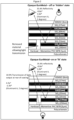
- Example 11 Bright chrome (Zero optical transmission - for illuminated patterns)
- This technique is used to provide a coating which has zero optical transmission through the coating. Portions of the coating can then be ablated through the full depth of the coating, via techniques such as laser etching, thereby forming patterns which can be illuminated by rear lighting. The zero photopic transmission of the coating prevents light bleed-through of the rear illumination source.
- a schematic representation of a coated substrate in accordance with this embodiment is illustrated in Figure 3 .
- this embodiment of the invention may take is the form of a decorative badge for an automobile.
- a decorative badge for an automobile comprises a plastic substrate formed in the desired shape of the badge with a zero optical transmission decorative coating in accordance with the present invention.
- Portions of the decorative coating are then laser etched or removed to introduce lettering and graphics into the coating which can be emphasized by underlying coloured material.
- individual highlights can be introduced into the coating in the form of portions of the coating that are completely removed from the substrate via laser ablation, or other acceptable means, to permit controlled light transmission through the coating.
- the badge can then be backlit to emphasize the highlights and to create a desired visual appeal.
- the coating system of the present invention enables such a decorative article.
- Example 1 A process as described in Example 1 is employed. With the following alterations.
- Example 13 Bright chrome (Zero optical transmission - low residual stress - Tensile).
Landscapes
- Chemical & Material Sciences (AREA)
- Organic Chemistry (AREA)
- Chemical Kinetics & Catalysis (AREA)
- Engineering & Computer Science (AREA)
- Materials Engineering (AREA)
- Health & Medical Sciences (AREA)
- Medicinal Chemistry (AREA)
- Polymers & Plastics (AREA)
- Metallurgy (AREA)
- Mechanical Engineering (AREA)
- Life Sciences & Earth Sciences (AREA)
- Wood Science & Technology (AREA)
- Inorganic Chemistry (AREA)
- Laminated Bodies (AREA)
- Physical Vapour Deposition (AREA)
Applications Claiming Priority (2)
| Application Number | Priority Date | Filing Date | Title |
|---|---|---|---|
| AU2014900781A AU2014900781A0 (en) | 2014-03-07 | Decorative Coatings for Plastic Substrates | |
| PCT/AU2015/000093 WO2015131223A1 (en) | 2014-03-07 | 2015-02-20 | Decorative coatings for plastic substrates |
Publications (3)
| Publication Number | Publication Date |
|---|---|
| EP3113946A1 EP3113946A1 (en) | 2017-01-11 |
| EP3113946A4 EP3113946A4 (en) | 2017-12-13 |
| EP3113946B1 true EP3113946B1 (en) | 2023-05-10 |
Family
ID=54054253
Family Applications (1)
| Application Number | Title | Priority Date | Filing Date |
|---|---|---|---|
| EP15759201.5A Active EP3113946B1 (en) | 2014-03-07 | 2015-02-20 | Decorative coatings for plastic substrates |
Country Status (7)
Families Citing this family (34)
| Publication number | Priority date | Publication date | Assignee | Title |
|---|---|---|---|---|
| US10703299B2 (en) | 2010-04-19 | 2020-07-07 | SMR Patents S.à.r.l. | Rear view mirror simulation |
| US10800329B2 (en) | 2010-04-19 | 2020-10-13 | SMR Patents S.à.r.l. | Rear view mirror simulation |
| US12090927B2 (en) | 2012-01-24 | 2024-09-17 | Motherson Innovations Company Limited | Light emitting mirror bezel |
| WO2018167096A1 (en) * | 2017-03-13 | 2018-09-20 | Motherson Innovations Company Ltd. | Light emitting mirror bezel |
| DE102017130246B4 (de) | 2017-12-15 | 2024-06-06 | Motherson Innovations Company Limited | Rückblickvorrichtung und Kraftfahrzeug |
| DE102017117024B4 (de) * | 2017-07-27 | 2021-01-21 | SMR Patents S.à.r.l. | Kameraanordnung und Kraftfahrzeug mit Kameraanordnung |
| EP3409537B1 (en) | 2017-05-30 | 2019-07-10 | SMR Patents S.à.r.l. | Head section for a rear view device |
| ES2693388A1 (es) * | 2017-06-09 | 2018-12-11 | Srg Global Liria, S.L | Molduras de apariencia metálica traslúcidas a la luz y enmascaradas para iluminación selectiva |
| WO2019004725A1 (ko) * | 2017-06-27 | 2019-01-03 | 주식회사 엘지화학 | 장식 부재 및 이의 제조방법 |
| KR101925467B1 (ko) | 2017-06-27 | 2018-12-05 | 주식회사 엘지화학 | 장식 부재 및 이의 제조방법 |
| DE102017117032B4 (de) * | 2017-07-27 | 2021-01-28 | SMR Patents S.à.r.l. | Kameraanordnung und Kraftfahrzeug mit Kameraanordnung |
| DE102017119542A1 (de) | 2017-08-25 | 2019-02-28 | SMR Patents S.à.r.l. | Rückblickvorrichtung und Fahrzeug mit einer solchen Rückblickvorrichtung |
| US20190112698A1 (en) * | 2017-10-12 | 2019-04-18 | Srg Global, Inc. | Trim component having textured surface supporting pvd-deposited coating, and/or method of making the same |
| KR102201575B1 (ko) * | 2017-12-15 | 2021-01-12 | 주식회사 엘지화학 | 장식 부재 |
| DE102018121580B4 (de) | 2018-09-04 | 2024-06-06 | Motherson Innovations Company Limited | Beleuchtungsvorrichtung und Rückblickvorrichtung damit |
| KR102594844B1 (ko) | 2018-04-10 | 2023-10-27 | 주식회사 엘지화학 | 장식 부재 |
| CN111683562B (zh) * | 2018-06-15 | 2022-11-15 | 株式会社Lg化学 | 装饰构件 |
| DE102019100669A1 (de) * | 2019-01-11 | 2020-07-16 | Motherson Innovations Company Limited | Elektromagnetischer Störschutz für Radome |
| CN109348660B (zh) * | 2018-11-16 | 2022-08-19 | 昇印光电(昆山)股份有限公司 | 装饰片及消费电子产品盖板 |
| WO2020236463A1 (en) * | 2019-05-22 | 2020-11-26 | Nanogate Technologies, Inc. | Coating process, and associated system and parts |
| WO2020249947A1 (en) * | 2019-06-10 | 2020-12-17 | Kenwood Limited | Kitchen appliance, decorative article therefor, and method of manufacturing a decorative surface |
| CN114270626A (zh) * | 2019-07-29 | 2022-04-01 | 玛泽森创新有限公司 | 第一表面或第二表面装饰性雷达天线罩 |
| WO2021043397A1 (de) * | 2019-09-04 | 2021-03-11 | Zkw Group Gmbh | Verfahren zum herstellen eines semitransparenten kraftfahrzeugdesignelements |
| US12249761B2 (en) | 2019-10-15 | 2025-03-11 | Motherson Innovations Company Limited | First surface decorative element |
| WO2021087511A1 (en) * | 2019-11-01 | 2021-05-06 | Nanogate Technologies, Inc. | Direct-to-substrate coating process, and associated system and parts |
| US12305270B2 (en) | 2019-11-07 | 2025-05-20 | Oerlikon Surface Solutions Ag, Pfäffikon | Method for producing a coating |
| CN111041413B (zh) * | 2019-12-11 | 2022-02-11 | 中国工程物理研究院激光聚变研究中心 | 一种提高大口径反射镜镀膜面形精度的方法 |
| US20210213884A1 (en) * | 2020-01-13 | 2021-07-15 | Ford Global Technologies, Llc | Running board and forming method |
| WO2021204635A1 (en) | 2020-04-08 | 2021-10-14 | Motherson Innovations Company Ltd. | Exterior rear view assembly and vehicle therewith |
| WO2023110058A1 (en) * | 2020-12-11 | 2023-06-22 | Oerlikon Surface Solutions Ag, Pfäffikon | Optically and optionally electromagnetically semi-transparent optimized coated component |
| CN116917530A (zh) * | 2021-01-14 | 2023-10-20 | 玛泽森创新有限公司 | 除基底硬涂层之外的装饰性涂层 |
| DE102022110747B3 (de) | 2022-05-02 | 2023-11-02 | Motherson Innovations Company Limited | Beleuchtungseinheit, fahrzeugkomponente und fahrzeug |
| DE102022113597B4 (de) * | 2022-05-30 | 2023-12-21 | Motherson Innovations Company Limited | Artikel mit einer dekorativen beschichtung und verfahren zu dessen herstellung |
| EP4566882A1 (en) | 2023-12-07 | 2025-06-11 | HELLA Saturnus Slovenija d.o.o. | Illumination device of or for a vehicle, cladding component of or for a vehicle, comprising such an illumination device and vehicle having such an illumination device or such a cladding component |
Family Cites Families (14)
| Publication number | Priority date | Publication date | Assignee | Title |
|---|---|---|---|---|
| EP0028903A1 (en) * | 1979-11-09 | 1981-05-20 | The D.L.Auld Company | Method for making decorative emblems having an ultrathin coating of plastic |
| US5763024A (en) * | 1995-02-28 | 1998-06-09 | Transfer Print Foils, Inc. | Trim component including a metalized polyester film and substrate having curled edges |
| US6231992B1 (en) * | 1998-09-04 | 2001-05-15 | Yazaki Corporation | Partial reflector |
| US6548128B2 (en) * | 2001-03-28 | 2003-04-15 | The Auld Company | Decorative emblems having an embedded image or design with an enhanced depth of vision and method of making same |
| US6558816B2 (en) | 2001-04-05 | 2003-05-06 | Vapor Technologies, Inc. | Coated article with polymeric basecoat having the appearance of stainless steel |
| WO2004026785A1 (de) * | 2002-09-14 | 2004-04-01 | Schott Ag | Beschichteter gegenstand |
| JP2005298833A (ja) * | 2002-10-22 | 2005-10-27 | Asahi Glass Co Ltd | 多層膜付き基板とその製造方法 |
| US7438952B2 (en) * | 2004-06-30 | 2008-10-21 | Ppg Industries Ohio, Inc. | Methods and systems for coating articles having a plastic substrate |
| DE102004032013B4 (de) * | 2004-07-02 | 2007-05-16 | Rehau Ag & Co | Multilagenschichtaufbau für Polymere, Verfahren zu dessen Herstellung und die Verwendung von Kunststoffformteilen mit dem Multilagenschichtaufbau |
| CA2598469C (en) * | 2005-02-12 | 2017-03-21 | Basf Catalysts Llc | Transparent goniochromatic multilayer effect pigment |
| JP5151234B2 (ja) * | 2007-04-26 | 2013-02-27 | 凸版印刷株式会社 | 加飾成形品 |
| JP2010102157A (ja) * | 2008-10-24 | 2010-05-06 | Seiko Epson Corp | 光学物品およびその製造方法 |
| KR101753226B1 (ko) * | 2009-12-24 | 2017-07-04 | 에스엠알 페턴츠 에스.에이.알.엘. | 플라스틱 자동차용 거울 |
| AU2012262012A1 (en) * | 2011-06-03 | 2013-12-12 | Frederick Goldman, Inc. | Coated metallic products and methods for making the same |
-
2015
- 2015-02-20 CN CN201580023757.5A patent/CN106457753B/zh active Active
- 2015-02-20 EP EP15759201.5A patent/EP3113946B1/en active Active
- 2015-02-20 AU AU2015226820A patent/AU2015226820B2/en active Active
- 2015-02-20 WO PCT/AU2015/000093 patent/WO2015131223A1/en active Application Filing
- 2015-02-20 JP JP2016572861A patent/JP6511474B2/ja active Active
- 2015-02-20 KR KR1020167027080A patent/KR101902669B1/ko active Active
- 2015-02-20 US US15/124,310 patent/US10066069B2/en active Active
Also Published As
| Publication number | Publication date |
|---|---|
| KR20170003529A (ko) | 2017-01-09 |
| EP3113946A4 (en) | 2017-12-13 |
| US20170015802A1 (en) | 2017-01-19 |
| WO2015131223A1 (en) | 2015-09-11 |
| JP2017508648A (ja) | 2017-03-30 |
| EP3113946A1 (en) | 2017-01-11 |
| AU2015226820A1 (en) | 2016-10-27 |
| AU2015226820B2 (en) | 2018-02-15 |
| CN106457753B (zh) | 2019-05-10 |
| JP6511474B2 (ja) | 2019-05-15 |
| KR101902669B1 (ko) | 2018-11-07 |
| US10066069B2 (en) | 2018-09-04 |
| CN106457753A (zh) | 2017-02-22 |
Similar Documents
| Publication | Publication Date | Title |
|---|---|---|
| EP3113946B1 (en) | Decorative coatings for plastic substrates | |
| EP2517055B1 (en) | Plastic automotive mirrors | |
| CN101784915B (zh) | 涂覆有包括部分在离子辅助下形成的子层的抗反射涂层的光学物品及其制造方法 | |
| CN107111000B (zh) | 包括在紫外区域具有高反射率的干涉涂层的光学物品 | |
| CN101617248A (zh) | 制造涂覆有具有改进的粘附性和耐磨性的抗反射涂层或反光涂层的光学制品的方法 | |
| CN106674566A (zh) | 涂布的聚合物衬底 | |
| Schulz et al. | Vacuum coating of plastic optics | |
| CN107085251A (zh) | 包括在可见光区具有非常低的反射的薄的减反射涂层的眼科镜片 | |
| CN120178390A (zh) | 具有低折射率层与高折射率层的厚度比得到优化的耐磨且耐温干涉涂层的光学制品 | |
| CN106662671A (zh) | 包括在紫外区和可见区内均具有低反射的减反射涂层的光学制品 | |
| FR3055157A1 (fr) | Lentille ophtalmique a revetement multicouche reflechissant et anti-abrasion, et son procede de fabrication. | |
| US20020136877A1 (en) | Reflection reducing coating | |
| WO2021255197A1 (en) | Optical article having a multilayered antireflective coating including an encapsulated metal film | |
| Zuber et al. | Enhanced abrasion resistance of ultrathin reflective coatings on polymeric substrates: an improvement upon glass substrates | |
| US20250084537A1 (en) | Decorative antique copper coating with htl compatibility and novel inter-layer adhesion mechanism | |
| CN107430211A (zh) | 具有低Rv和低Ruv的减反射溅射叠层 | |
| EP3165631B1 (en) | Coated polymeric substrates | |
| WO2010032783A1 (ja) | 光学干渉薄膜 | |
| US20240102149A1 (en) | Decorative coating excluding a base hard-coat |
Legal Events
| Date | Code | Title | Description |
|---|---|---|---|
| PUAI | Public reference made under article 153(3) epc to a published international application that has entered the european phase |
Free format text: ORIGINAL CODE: 0009012 |
|
| STAA | Information on the status of an ep patent application or granted ep patent |
Free format text: STATUS: REQUEST FOR EXAMINATION WAS MADE |
|
| 17P | Request for examination filed |
Effective date: 20160907 |
|
| AK | Designated contracting states |
Kind code of ref document: A1 Designated state(s): AL AT BE BG CH CY CZ DE DK EE ES FI FR GB GR HR HU IE IS IT LI LT LU LV MC MK MT NL NO PL PT RO RS SE SI SK SM TR |
|
| AX | Request for extension of the european patent |
Extension state: BA ME |
|
| DAX | Request for extension of the european patent (deleted) | ||
| A4 | Supplementary search report drawn up and despatched |
Effective date: 20171109 |
|
| RIC1 | Information provided on ipc code assigned before grant |
Ipc: B32B 15/00 20060101ALI20171103BHEP Ipc: B32B 7/00 20060101AFI20171103BHEP |
|
| RAP1 | Party data changed (applicant data changed or rights of an application transferred) |
Owner name: SMR PATENTS S.A.R.L. Owner name: UNIVERSITY OF SOUTH AUSTRALIA |
|
| STAA | Information on the status of an ep patent application or granted ep patent |
Free format text: STATUS: EXAMINATION IS IN PROGRESS |
|
| 17Q | First examination report despatched |
Effective date: 20210409 |
|
| STAA | Information on the status of an ep patent application or granted ep patent |
Free format text: STATUS: EXAMINATION IS IN PROGRESS |
|
| GRAP | Despatch of communication of intention to grant a patent |
Free format text: ORIGINAL CODE: EPIDOSNIGR1 |
|
| STAA | Information on the status of an ep patent application or granted ep patent |
Free format text: STATUS: GRANT OF PATENT IS INTENDED |
|
| INTG | Intention to grant announced |
Effective date: 20220926 |
|
| GRAJ | Information related to disapproval of communication of intention to grant by the applicant or resumption of examination proceedings by the epo deleted |
Free format text: ORIGINAL CODE: EPIDOSDIGR1 |
|
| STAA | Information on the status of an ep patent application or granted ep patent |
Free format text: STATUS: EXAMINATION IS IN PROGRESS |
|
| INTC | Intention to grant announced (deleted) | ||
| GRAS | Grant fee paid |
Free format text: ORIGINAL CODE: EPIDOSNIGR3 |
|
| STAA | Information on the status of an ep patent application or granted ep patent |
Free format text: STATUS: GRANT OF PATENT IS INTENDED |
|
| GRAP | Despatch of communication of intention to grant a patent |
Free format text: ORIGINAL CODE: EPIDOSNIGR1 |
|
| GRAA | (expected) grant |
Free format text: ORIGINAL CODE: 0009210 |
|
| STAA | Information on the status of an ep patent application or granted ep patent |
Free format text: STATUS: THE PATENT HAS BEEN GRANTED |
|
| INTG | Intention to grant announced |
Effective date: 20230321 |
|
| RIN1 | Information on inventor provided before grant (corrected) |
Inventor name: CARUSO, DEAN Inventor name: FIELD, SIMON DAVID Inventor name: EVANS, DREW RAYMOND Inventor name: HALL, COLIN JAMES |
|
| AK | Designated contracting states |
Kind code of ref document: B1 Designated state(s): AL AT BE BG CH CY CZ DE DK EE ES FI FR GB GR HR HU IE IS IT LI LT LU LV MC MK MT NL NO PL PT RO RS SE SI SK SM TR |
|
| REG | Reference to a national code |
Ref country code: GB Ref legal event code: FG4D |
|
| REG | Reference to a national code |
Ref country code: AT Ref legal event code: REF Ref document number: 1566299 Country of ref document: AT Kind code of ref document: T Effective date: 20230515 Ref country code: CH Ref legal event code: EP |
|
| REG | Reference to a national code |
Ref country code: DE Ref legal event code: R096 Ref document number: 602015083522 Country of ref document: DE |
|
| REG | Reference to a national code |
Ref country code: IE Ref legal event code: FG4D |
|
| P01 | Opt-out of the competence of the unified patent court (upc) registered |
Effective date: 20230616 |
|
| REG | Reference to a national code |
Ref country code: LT Ref legal event code: MG9D |
|
| REG | Reference to a national code |
Ref country code: NL Ref legal event code: MP Effective date: 20230510 |
|
| REG | Reference to a national code |
Ref country code: AT Ref legal event code: MK05 Ref document number: 1566299 Country of ref document: AT Kind code of ref document: T Effective date: 20230510 |
|
| PG25 | Lapsed in a contracting state [announced via postgrant information from national office to epo] |
Ref country code: SE Free format text: LAPSE BECAUSE OF FAILURE TO SUBMIT A TRANSLATION OF THE DESCRIPTION OR TO PAY THE FEE WITHIN THE PRESCRIBED TIME-LIMIT Effective date: 20230510 Ref country code: PT Free format text: LAPSE BECAUSE OF FAILURE TO SUBMIT A TRANSLATION OF THE DESCRIPTION OR TO PAY THE FEE WITHIN THE PRESCRIBED TIME-LIMIT Effective date: 20230911 Ref country code: NO Free format text: LAPSE BECAUSE OF FAILURE TO SUBMIT A TRANSLATION OF THE DESCRIPTION OR TO PAY THE FEE WITHIN THE PRESCRIBED TIME-LIMIT Effective date: 20230810 Ref country code: NL Free format text: LAPSE BECAUSE OF FAILURE TO SUBMIT A TRANSLATION OF THE DESCRIPTION OR TO PAY THE FEE WITHIN THE PRESCRIBED TIME-LIMIT Effective date: 20230510 Ref country code: ES Free format text: LAPSE BECAUSE OF FAILURE TO SUBMIT A TRANSLATION OF THE DESCRIPTION OR TO PAY THE FEE WITHIN THE PRESCRIBED TIME-LIMIT Effective date: 20230510 Ref country code: AT Free format text: LAPSE BECAUSE OF FAILURE TO SUBMIT A TRANSLATION OF THE DESCRIPTION OR TO PAY THE FEE WITHIN THE PRESCRIBED TIME-LIMIT Effective date: 20230510 |
|
| PG25 | Lapsed in a contracting state [announced via postgrant information from national office to epo] |
Ref country code: RS Free format text: LAPSE BECAUSE OF FAILURE TO SUBMIT A TRANSLATION OF THE DESCRIPTION OR TO PAY THE FEE WITHIN THE PRESCRIBED TIME-LIMIT Effective date: 20230510 Ref country code: PL Free format text: LAPSE BECAUSE OF FAILURE TO SUBMIT A TRANSLATION OF THE DESCRIPTION OR TO PAY THE FEE WITHIN THE PRESCRIBED TIME-LIMIT Effective date: 20230510 Ref country code: LV Free format text: LAPSE BECAUSE OF FAILURE TO SUBMIT A TRANSLATION OF THE DESCRIPTION OR TO PAY THE FEE WITHIN THE PRESCRIBED TIME-LIMIT Effective date: 20230510 Ref country code: LT Free format text: LAPSE BECAUSE OF FAILURE TO SUBMIT A TRANSLATION OF THE DESCRIPTION OR TO PAY THE FEE WITHIN THE PRESCRIBED TIME-LIMIT Effective date: 20230510 Ref country code: IS Free format text: LAPSE BECAUSE OF FAILURE TO SUBMIT A TRANSLATION OF THE DESCRIPTION OR TO PAY THE FEE WITHIN THE PRESCRIBED TIME-LIMIT Effective date: 20230910 Ref country code: HR Free format text: LAPSE BECAUSE OF FAILURE TO SUBMIT A TRANSLATION OF THE DESCRIPTION OR TO PAY THE FEE WITHIN THE PRESCRIBED TIME-LIMIT Effective date: 20230510 Ref country code: GR Free format text: LAPSE BECAUSE OF FAILURE TO SUBMIT A TRANSLATION OF THE DESCRIPTION OR TO PAY THE FEE WITHIN THE PRESCRIBED TIME-LIMIT Effective date: 20230811 |
|
| PG25 | Lapsed in a contracting state [announced via postgrant information from national office to epo] |
Ref country code: FI Free format text: LAPSE BECAUSE OF FAILURE TO SUBMIT A TRANSLATION OF THE DESCRIPTION OR TO PAY THE FEE WITHIN THE PRESCRIBED TIME-LIMIT Effective date: 20230510 |
|
| PG25 | Lapsed in a contracting state [announced via postgrant information from national office to epo] |
Ref country code: SK Free format text: LAPSE BECAUSE OF FAILURE TO SUBMIT A TRANSLATION OF THE DESCRIPTION OR TO PAY THE FEE WITHIN THE PRESCRIBED TIME-LIMIT Effective date: 20230510 |
|
| PG25 | Lapsed in a contracting state [announced via postgrant information from national office to epo] |
Ref country code: SM Free format text: LAPSE BECAUSE OF FAILURE TO SUBMIT A TRANSLATION OF THE DESCRIPTION OR TO PAY THE FEE WITHIN THE PRESCRIBED TIME-LIMIT Effective date: 20230510 Ref country code: SK Free format text: LAPSE BECAUSE OF FAILURE TO SUBMIT A TRANSLATION OF THE DESCRIPTION OR TO PAY THE FEE WITHIN THE PRESCRIBED TIME-LIMIT Effective date: 20230510 Ref country code: RO Free format text: LAPSE BECAUSE OF FAILURE TO SUBMIT A TRANSLATION OF THE DESCRIPTION OR TO PAY THE FEE WITHIN THE PRESCRIBED TIME-LIMIT Effective date: 20230510 Ref country code: EE Free format text: LAPSE BECAUSE OF FAILURE TO SUBMIT A TRANSLATION OF THE DESCRIPTION OR TO PAY THE FEE WITHIN THE PRESCRIBED TIME-LIMIT Effective date: 20230510 Ref country code: DK Free format text: LAPSE BECAUSE OF FAILURE TO SUBMIT A TRANSLATION OF THE DESCRIPTION OR TO PAY THE FEE WITHIN THE PRESCRIBED TIME-LIMIT Effective date: 20230510 Ref country code: CZ Free format text: LAPSE BECAUSE OF FAILURE TO SUBMIT A TRANSLATION OF THE DESCRIPTION OR TO PAY THE FEE WITHIN THE PRESCRIBED TIME-LIMIT Effective date: 20230510 |
|
| REG | Reference to a national code |
Ref country code: DE Ref legal event code: R097 Ref document number: 602015083522 Country of ref document: DE |
|
| PLBE | No opposition filed within time limit |
Free format text: ORIGINAL CODE: 0009261 |
|
| STAA | Information on the status of an ep patent application or granted ep patent |
Free format text: STATUS: NO OPPOSITION FILED WITHIN TIME LIMIT |
|
| 26N | No opposition filed |
Effective date: 20240213 |
|
| PG25 | Lapsed in a contracting state [announced via postgrant information from national office to epo] |
Ref country code: SI Free format text: LAPSE BECAUSE OF FAILURE TO SUBMIT A TRANSLATION OF THE DESCRIPTION OR TO PAY THE FEE WITHIN THE PRESCRIBED TIME-LIMIT Effective date: 20230510 |
|
| PG25 | Lapsed in a contracting state [announced via postgrant information from national office to epo] |
Ref country code: SI Free format text: LAPSE BECAUSE OF FAILURE TO SUBMIT A TRANSLATION OF THE DESCRIPTION OR TO PAY THE FEE WITHIN THE PRESCRIBED TIME-LIMIT Effective date: 20230510 Ref country code: IT Free format text: LAPSE BECAUSE OF FAILURE TO SUBMIT A TRANSLATION OF THE DESCRIPTION OR TO PAY THE FEE WITHIN THE PRESCRIBED TIME-LIMIT Effective date: 20230510 |
|
| PG25 | Lapsed in a contracting state [announced via postgrant information from national office to epo] |
Ref country code: MC Free format text: LAPSE BECAUSE OF FAILURE TO SUBMIT A TRANSLATION OF THE DESCRIPTION OR TO PAY THE FEE WITHIN THE PRESCRIBED TIME-LIMIT Effective date: 20230510 |
|
| REG | Reference to a national code |
Ref country code: CH Ref legal event code: PL |
|
| PG25 | Lapsed in a contracting state [announced via postgrant information from national office to epo] |
Ref country code: LU Free format text: LAPSE BECAUSE OF NON-PAYMENT OF DUE FEES Effective date: 20240220 |
|
| PG25 | Lapsed in a contracting state [announced via postgrant information from national office to epo] |
Ref country code: CH Free format text: LAPSE BECAUSE OF NON-PAYMENT OF DUE FEES Effective date: 20240229 |
|
| PG25 | Lapsed in a contracting state [announced via postgrant information from national office to epo] |
Ref country code: LU Free format text: LAPSE BECAUSE OF NON-PAYMENT OF DUE FEES Effective date: 20240220 Ref country code: CH Free format text: LAPSE BECAUSE OF NON-PAYMENT OF DUE FEES Effective date: 20240229 |
|
| PG25 | Lapsed in a contracting state [announced via postgrant information from national office to epo] |
Ref country code: BG Free format text: LAPSE BECAUSE OF FAILURE TO SUBMIT A TRANSLATION OF THE DESCRIPTION OR TO PAY THE FEE WITHIN THE PRESCRIBED TIME-LIMIT Effective date: 20230510 |
|
| PG25 | Lapsed in a contracting state [announced via postgrant information from national office to epo] |
Ref country code: BG Free format text: LAPSE BECAUSE OF FAILURE TO SUBMIT A TRANSLATION OF THE DESCRIPTION OR TO PAY THE FEE WITHIN THE PRESCRIBED TIME-LIMIT Effective date: 20230510 |
|
| REG | Reference to a national code |
Ref country code: BE Ref legal event code: MM Effective date: 20240229 |
|
| PG25 | Lapsed in a contracting state [announced via postgrant information from national office to epo] |
Ref country code: BE Free format text: LAPSE BECAUSE OF NON-PAYMENT OF DUE FEES Effective date: 20240229 |
|
| PG25 | Lapsed in a contracting state [announced via postgrant information from national office to epo] |
Ref country code: IE Free format text: LAPSE BECAUSE OF NON-PAYMENT OF DUE FEES Effective date: 20240220 |
|
| PG25 | Lapsed in a contracting state [announced via postgrant information from national office to epo] |
Ref country code: IE Free format text: LAPSE BECAUSE OF NON-PAYMENT OF DUE FEES Effective date: 20240220 Ref country code: BE Free format text: LAPSE BECAUSE OF NON-PAYMENT OF DUE FEES Effective date: 20240229 |
|
| PGFP | Annual fee paid to national office [announced via postgrant information from national office to epo] |
Ref country code: DE Payment date: 20250218 Year of fee payment: 11 |
|
| PGFP | Annual fee paid to national office [announced via postgrant information from national office to epo] |
Ref country code: FR Payment date: 20250220 Year of fee payment: 11 |
|
| PGFP | Annual fee paid to national office [announced via postgrant information from national office to epo] |
Ref country code: GB Payment date: 20250220 Year of fee payment: 11 |
|
| PG25 | Lapsed in a contracting state [announced via postgrant information from national office to epo] |
Ref country code: CY Free format text: LAPSE BECAUSE OF FAILURE TO SUBMIT A TRANSLATION OF THE DESCRIPTION OR TO PAY THE FEE WITHIN THE PRESCRIBED TIME-LIMIT; INVALID AB INITIO Effective date: 20150220 |
|
| PG25 | Lapsed in a contracting state [announced via postgrant information from national office to epo] |
Ref country code: HU Free format text: LAPSE BECAUSE OF FAILURE TO SUBMIT A TRANSLATION OF THE DESCRIPTION OR TO PAY THE FEE WITHIN THE PRESCRIBED TIME-LIMIT; INVALID AB INITIO Effective date: 20150220 |