EP3111725B1 - Beleuchtungssystem und beleuchtungsverfahren - Google Patents
Beleuchtungssystem und beleuchtungsverfahren Download PDFInfo
- Publication number
- EP3111725B1 EP3111725B1 EP15704536.0A EP15704536A EP3111725B1 EP 3111725 B1 EP3111725 B1 EP 3111725B1 EP 15704536 A EP15704536 A EP 15704536A EP 3111725 B1 EP3111725 B1 EP 3111725B1
- Authority
- EP
- European Patent Office
- Prior art keywords
- lighting
- intensity
- general
- color
- lighting unit
- Prior art date
- Legal status (The legal status is an assumption and is not a legal conclusion. Google has not performed a legal analysis and makes no representation as to the accuracy of the status listed.)
- Active
Links
- 238000000034 method Methods 0.000 title claims description 9
- 238000013507 mapping Methods 0.000 claims description 16
- 230000002301 combined effect Effects 0.000 claims description 4
- 230000001419 dependent effect Effects 0.000 claims 1
- 238000005286 illumination Methods 0.000 description 16
- 238000013459 approach Methods 0.000 description 10
- 230000004044 response Effects 0.000 description 5
- 230000008859 change Effects 0.000 description 4
- 238000001514 detection method Methods 0.000 description 2
- 230000004907 flux Effects 0.000 description 2
- 238000005259 measurement Methods 0.000 description 2
- 230000005457 Black-body radiation Effects 0.000 description 1
- 238000004378 air conditioning Methods 0.000 description 1
- 238000003491 array Methods 0.000 description 1
- 230000008901 benefit Effects 0.000 description 1
- OIQPTROHQCGFEF-UHFFFAOYSA-L chembl1371409 Chemical compound [Na+].[Na+].OC1=CC=C2C=C(S([O-])(=O)=O)C=CC2=C1N=NC1=CC=C(S([O-])(=O)=O)C=C1 OIQPTROHQCGFEF-UHFFFAOYSA-L 0.000 description 1
- 238000011161 development Methods 0.000 description 1
- 238000010586 diagram Methods 0.000 description 1
- 230000000694 effects Effects 0.000 description 1
- 238000003306 harvesting Methods 0.000 description 1
- 230000010354 integration Effects 0.000 description 1
- 230000002093 peripheral effect Effects 0.000 description 1
- 230000008569 process Effects 0.000 description 1
- 230000000007 visual effect Effects 0.000 description 1
Images


Classifications
-
- H—ELECTRICITY
- H05—ELECTRIC TECHNIQUES NOT OTHERWISE PROVIDED FOR
- H05B—ELECTRIC HEATING; ELECTRIC LIGHT SOURCES NOT OTHERWISE PROVIDED FOR; CIRCUIT ARRANGEMENTS FOR ELECTRIC LIGHT SOURCES, IN GENERAL
- H05B45/00—Circuit arrangements for operating light-emitting diodes [LED]
- H05B45/20—Controlling the colour of the light
- H05B45/22—Controlling the colour of the light using optical feedback
-
- H—ELECTRICITY
- H05—ELECTRIC TECHNIQUES NOT OTHERWISE PROVIDED FOR
- H05B—ELECTRIC HEATING; ELECTRIC LIGHT SOURCES NOT OTHERWISE PROVIDED FOR; CIRCUIT ARRANGEMENTS FOR ELECTRIC LIGHT SOURCES, IN GENERAL
- H05B47/00—Circuit arrangements for operating light sources in general, i.e. where the type of light source is not relevant
- H05B47/10—Controlling the light source
- H05B47/105—Controlling the light source in response to determined parameters
- H05B47/11—Controlling the light source in response to determined parameters by determining the brightness or colour temperature of ambient light
-
- Y—GENERAL TAGGING OF NEW TECHNOLOGICAL DEVELOPMENTS; GENERAL TAGGING OF CROSS-SECTIONAL TECHNOLOGIES SPANNING OVER SEVERAL SECTIONS OF THE IPC; TECHNICAL SUBJECTS COVERED BY FORMER USPC CROSS-REFERENCE ART COLLECTIONS [XRACs] AND DIGESTS
- Y02—TECHNOLOGIES OR APPLICATIONS FOR MITIGATION OR ADAPTATION AGAINST CLIMATE CHANGE
- Y02B—CLIMATE CHANGE MITIGATION TECHNOLOGIES RELATED TO BUILDINGS, e.g. HOUSING, HOUSE APPLIANCES OR RELATED END-USER APPLICATIONS
- Y02B20/00—Energy efficient lighting technologies, e.g. halogen lamps or gas discharge lamps
- Y02B20/40—Control techniques providing energy savings, e.g. smart controller or presence detection
Definitions
- the invention relates to a lighting system having general lighting and directed (accented) lighting.
- the accented lighting may be task light for illuminating a work station in a home or office or it can be directed lighting for illuminating an object on display in applications such as retail outlets or museum spaces.
- the invention relates to lighting systems which enable control of the color temperature of the light output, and which also takes account of the daylight level.
- day light harvesting There is a general desire to use more daylight lighting in indoor spaces this to save energy on artificial lighting and to provide more natural lighting scenes. This development is called day light harvesting.
- Shop owners for example are interested to allow more daylight into their sales spaces, for example to save energy and to establish a green image for their brand.
- the problem however is that day light is dynamic and changes. The color temperature changes over day due to the position of the sun (more blue in morning and more warm in the evening time) and also the light level will vary over the course of a day in relation to the time of the day, the season and the weather conditions outside. Shop owners want to control their lighting conditions.
- light is formed by a combination of incident daylight and added artificial light.
- the daylight cannot be influenced, or only to a limited extent, by the user, for example by opening or closing a blind. This makes control of the artificial light all the more important.
- a lighting system which takes account of the daylight level, notably for the artificial lighting of office buildings.
- a light sensor is provided for measuring the daylight level, and a control signal is derived from the daylight level.
- a control unit is then arranged to switch on the artificial light when the measured daylight level drops below a predetermined minimum or, conversely, to switch off the artificial light when the measured daylight level exceeds a predetermined maximum.
- the control unit adjusts the intensity of the artificial light mainly inversely proportionally to the level of the daylight.
- the sensors can be installed on the most important planes in the space to be illuminated. In a supermarket for example they can be installed on racks in the corridors. In a hospital, the sensing can be for the horizontal level of the patient's bed. By measuring the lighting level it is possible to control the general lighting level by dimming or increasing the artificial general lighting, to maintain an overall minimal lighting level.
- WO 96/28956 discloses a system which enables the color point of (fluorescent) lighting to be controlled in dependence on the ambient light level.
- JP-2006/210045 discloses a method for operating a lighting system.
- the method comprises a step of regularly referring to a database control logic, a step of controlling a color temperature of ambient lighting to meet a predetermined color temperature corresponding to a time zone, a step of obtaining integration values of outdoor light and indoor light, respectively, and a step of controlling the slant angle of an electric blind and the illuminance intensity of ambient lighting as to make an outdoor-light-to-indoorlight ratio meet to a target ratio of the database control logic.
- Actual entry light into a room through a window is adjusted to meet a predetermined ratio of outdoor light by the electric blind even if outdoor light strongly enters at a low angle.
- the illuminance intensity of ambient lighting is adjusted, so that outdoor light and indoor light can be dynamically mixed in a balanced manner, and so that indoor lighting taking outdoor light into account is appropriately performed.
- JP-HI 1-162216 discloses a method wherein a work area and a periphery area on a top face of a plurality of work desks are illuminated by work area illuminating light source luminaires and peripheral area illuminating light sources, and a general area in a room other than top face of the desk is illuminated by a general area illuminating light source.
- JP-2010/212095 discloses a task lighting system that includes a task light emitting unit, a control unit that changes a color temperature of light emitted from the task light emitting unit along a black body radiation locus, and a task light emitting unit.
- the task light emitting unit includes a color temperature detection unit that detects the color temperature of light received from other than the task light emitting unit and a storage unit. When the color temperature detected by the color temperature detection unit is higher than a predetermined reference value, the control unit emits light having a color temperature higher than the reference color temperature stored in the storage unit.
- the task light emitting unit is controlled to irradiate, and when the detected color temperature is lower than the reference value, control is performed to irradiate light having a color temperature lower than the reference color temperature. Thereby, the color temperature of the light emitted by the task light emitting unit is controlled in accordance with the change in the color temperature of the light due to ambient illumination and external light.
- This invention relates in particular to lighting systems which includes general lighting units and accent lighting (by which is meant a more directed and generally higher intensity lighting).
- general lighting units by which is meant a more directed and generally higher intensity lighting.
- accent lighting by which is meant a more directed and generally higher intensity lighting.
- a problem arises that as the general lighting is changed, for example in response to the ambient light conditions, the effectiveness of the accent lighting alters. This can reduce the benefit of the accented lighting, either to provide a brighter workspace or to illuminate objects on show.
- the invention is as defined in system claim 1 and method claim 6
- the invention is based on the recognition that directed (accent) lighting can look inconsistent when the general lighting level is changed in response to daylight conditions.
- the directed lighting is thus controlled together with the general lighting to maintain a desired effect or appearance of the directed lighting.
- the invention is of particular interest for lighting of spaces where both general atmosphere and localized presentation are important, such as shops, museums, restaurants, bars, hospitals, offices, education centers, etc.
- the characteristics of light detected by the sensor are intensity, color and color temperature.
- the sensor arrangement is for detecting a general lighting intensity in the first area, and the predetermined relationship is a ratio between the general lighting intensity and the intensity of the second lighting unit output.
- the directed lighting can be maintained at a brighter level than the general lighting. It can always be a fixed factor higher in brightness, or a more complicated relationship between the two brightness levels can be established. If directed lighting is for example used to place emphasis on a product, this emphasis can be maintained even as the general illumination level changes.
- the ratio can be maintained while the intensity of the second lighting unit output does not exceed a maximum intensity. When this maximum intensity is reached it may be kept constant at this level or turned off because the general illumination is already so bright.
- the sensor arrangement is also for detecting a general lighting color in the first area, and the predetermined relationship is a mapping between a color characteristic of the general lighting and a color characteristic of the light output from the second lighting unit. As the general lighting changes color (for example because there is a component derived from ambient daylight which changes color with the time of day, weather or season), a contrast in color can be maintained between the general lighting and the accent lighting.
- the word mapping can be understood to follow the meaning as understood by those skilled in the art, that is to say; an operation that associates each element of a given set with one or more elements of a second set.
- the mapping can comprise mapping a high color temperature general lighting to a lower color temperature directed lighting output and mapping a low color temperature general lighting to a higher color temperature directed lighting output. In this way, the color temperatures of the two types of light (general and accent) are kept different to maintain a color contrast.
- the system is able to create a controlled contrast in dynamic general lighting spaces by changing the maximum intensity of a secondary light source as well as creating a difference in color temperature to create a preferred lighting of specific areas within the general space.
- a difference in light intensity between an object and the surroundings intensity contrast
- the system is able to increase the attention given to a special area or object on display. By selecting different shades of white lighting for example (i.e. different color temperatures) more depth can be created in a particular space or to a particular presentation area.
- the sensor arrangement can comprise a sensor for detecting the outdoor daylight intensity and/or color.
- a knowledge of how much natural light enters the first area can then be used to determine the required output from the first lighting unit. In turn, this enables the general lighting intensity and/or color in the first area to be derived.
- the desired output of the second lighting unit can then be derived.
- the sensor arrangement of the invention comprises a sensor for detecting the general light intensity and color in the first area. This sensor then measures the combined effect of any natural daylight which has entered the area and the first lighting unit. This enables a feedback control of the first lighting unit. The desired output of the second lighting unit can then be derived again from the general lighting in the first area.
- the sensor for measuring the general lighting is away from the output of the second lighting unit.
- the second lighting unit can for example comprise:
- These objects can be items for sale, or items being displayed such as art objects.
- the first and second lighting units can each comprise LED arrangements with controllable intensity and color temperature.
- the invention provides a lighting system having a first lighting unit for providing general lighting and a second lighting unit for providing directed lighting.
- the lighting units are controlled based on sensed light conditions, in order to maintain an intensity and/or color contrast between the general lighting and the directed lighting.
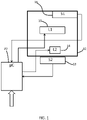
- FIG. 1 shows a general block diagram of a lighting system in accordance with the invention.
- the lighting system comprises at least a first light source 10 (L1) for providing general artificial illumination to an indoor space 12, and a second light source 14 (L2) for providing directed lighting.
- the directed lighting is typically higher intensity light and it provides direct illumination to a smaller area than the general lighting of the first light source 10.
- the area illuminated by the second light source 14 is however also illuminated by the first light source.
- the indoor space is also able to receive daylight, through a window, skylight or other opening.
- At least the second light source 14 has an adjustable intensity and color temperature.
- the first light source has at least an adjustable intensity, and it may also have an adjustable color temperature.
- a light source having an adjustable color temperature can be formed, for example by combining at least two dimmable light sources, each of which has a fixed, different color temperature.
- the light sources can be fluorescent lamps or LEDs or indeed any other type of lamps.
- the color temperature can be adjusted through a very wide range when a lamp having a fixed low color temperature for example of 2700 K is combined with a lamp having a high fixed color temperature for example of 6500 K.
- the color temperature can be adjusted by changing the flux ratio of the lamps, and this is possible with the total flux being maintained.
- the concept is to control the light sources 10,14 to maintain the effectiveness of the directed lighting.
- This directed lighting is often referred to as accent lighting.
- the effectiveness of the accent lighting is influenced by the general lighting, and this in turn is influenced by the ambient daylight which enters the space.
- FIG. 1 shows a first sensor 16 (S1) in the indoor space for sensing the general lighting level. This sensor will sense the combined lighting created by the first light source 10 and the ambient daylight.
- a second sensor 18 (S2) is shown outside indoor space for sensing the daylight level. This sensor will sense only the ambient daylight. It can instead be arranged inside the indoor space, facing a window for example so that its output is dominated by the ambient daylight.
- Ambient light sensors can be provided both inside and outside the indoor space if desired.
- the orientation of the light sensors can be selected.
- a sensor can be oriented in the horizontal plane to detect incident light from above, or in a vertical plane to detect horizontal incident light.
- the light sensing for detecting the general lighting level can combine multiple sensors in with different orientations to derive the desired measurement.
- the ambient light measurement will be selected so that it best represents the base lighting level as perceived by the user of the system when viewing the object for which there is accented lighting.
- the system can thus be implemented with a single sensor or a combination of sensors, and each sensor can comprise a single sensing element or multiple sensing elements with different orientations.
- control can be based on intensity control, or color temperature control or a combination of these.
- intensity control only, the sensors may only need to detect intensity levels, whereas for color temperature control, color sensing is needed.
- a controller 20 provides control of the first and second light sources 10,14, in particular to apply a predetermined relationship between the general lighting and the accent lighting to maintain an intensity and/or color contrast between them.
- a first approach is to control the intensity of the second light source (the accent/task lighting) in dependence on the general illumination level in the space. For example the same accent factor can be maintained, where the accent factor is defined as the ratio of the intensity of the accent lighting to the intensity of the background lighting. With increasing daylight lighting levels, more daylight enters the indoor space, so the accent lighting intensity should then be increased to keep the same accent factor, which means a specific level of contrast is maintained.
- the relationship which is maintained is a ratio between the general lighting intensity and the intensity of the second lighting unit output.
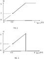
- Figure 2 shows one possible relationship between the intensity of the general illumination as detected by the first sensor 16 and the intensity 12 of the directed light as provided under the control of the controller.
- the general illumination intensity is normalized to values between 0 and 1, and it represents the combined effect of the artificial light provided by the first light source 10 and the ambient light entering the indoor space.
- the general illumination level is maintained above 0.4. This is achieved by control of the first light source 10 in known manner. For this reason the graph starts at 0.4 on the x-axis.
- the intensity 12 of the second light source 14 is shown to be adjustable between 0 and 5.
- the example shows a lowest level of 2 applied to give a desired contrast, and this increases as the intensity increases in a linear manner, to implement a ratio between the two intensities.
- the general illumination intensity may be kept to 0.4. This level increases if there is a significant amount of daylight entering.
- the ratio is maintained while the intensity of the second lighting unit output does not exceed a maximum intensity.
- the intensity when the second light source is at full output (shown as intensity 5), the intensity then becomes constant.
- the ratio between intensities is thus implemented for a range of driving conditions of the second light source. Within this driving range, the accent factor can be constant.
- the accent lighting can be automatically switched off to save energy.
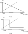
- the intensity of the first light source 10 is controlled to reduce the intensity when the daylight can provide a contribution to the general illumination. This is a known automatic dimming solution, and for completeness an example of the implemented control is shown in Figure 4 .
- Figure 4 shows how the general lighting intensity II provided by first light source 10 varies as a function of the daylight intensity level as detected by the sensor 18 (S2).
- the first light source 10 provides the illumination, but the intensity I1 can be dropped when the daylight provides a contribution.
- a second approach is to control the color temperature intensity of the second light source (the accent lighting) in dependence on the color temperature in the interior space.
- a sensor can measure the color temperature of the daylight entering the space, or a sensor can measure the color temperature in the space, or both.
- a color contrast will be made at the area illuminated by the second light source, such as warm spot lighting on a cool illuminated background.
- the color contrast can create extra attention value which is important for example in retail environments.
- Figure 5 shows a possible relationship between the color temperature T2 output by the second light source and the color temperature of general lighting (Tgeneral) as detected by sensor 16 (S1). There is an inverse relationship as shown to create the contrast explained above.
- Figure 6 shows an approach in which the second light source only has two color temperature settings - the high color temperature setting is used for low temperature general lighting, and the low color temperature setting is used for high temperature general lighting.
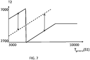
- Figure 7 shows a third approach in which a minimum difference in color temperature is maintained (as shown by the arrows).
- the color temperature provided by the second light source ramps linearly with the color temperature of the general lighting until a maximum is reached, at which point it switches to the lowest color temperature setting.
- hysteresis can be built into the algorithm, so that the color temperature T2 remains stable until there has been a sufficient change in the general lighting temperature T1.
- the general lighting color temperature can be measured by the internal sensor 16. However, it can also be derived from the measured daylight sensor 18 by taking into account the known additional lighting provided by the first light source 10. Thus, in the same way as the intensity control approach, the color temperature control approach can be implemented with a single sensor, and multiple sensors as shown in Figure 1 are not essential.
- FIGS 8 to 11 show a possible use of the system.
- the indoor space is for example a supermarket with shelves 30 having dedicated lighting 32, which corresponds to the second light source described above.
- the main lighting is shown as light source 34.
- Natural daylight can enter the room through the roof window 36.
- the sun has just risen on a clear day, and thus has a warm light color (low color temperature) and high intensity.
- the general lighting has intensity I1 and color temperature T1. This can be low intensity lighting (so that the color temperature of the ambient light dominates the color temperature of the general lighting in the room).
- the extra directed lighting has a higher intensity 12 and/or a different color temperature T2, such as cool (high color temperature) lighting. This provided both intensity and color contrast, although only one of these may suffice.
- FIG 9 a cloudy day is shown, and thus there is lower intensity cooler outdoor light.
- the general lighting needs a higher intensity I1 and again has a color temperature T1. Because the general lighting is predominantly artificial, there is more possibility to control the color temperature prevailing in the space.
- the directed lighting has a higher intensity 12 and/or a different color temperature T2 to the prevailing general lighting.
- Figures 10 and 11 show that the lighting control can change during the course of the day.
- Figure 10 corresponds to Figure 8 with a yellow sun at the start of the day, and Figure 11 shows the end of the same day.
- the ambient light becomes redder and has a different intensity at sunset so the settings I1, T and 12, T2 are adapted over the course of the day.
- the system described enables preferred lighting scenes to be defined in relation to the various possible daylight circumstances.
- the desired relationships can be provided as pre-set parameter combinations in a database. In this way, it is possible to obtain the right general and accent lighting setting to be combined with the prevailing daylight situation.
- the database can be tailored to the wishes of the user of the space. Each individual user can set a preferred balance between the color temperature of the general lighting and the accent lighting.
- the database with preferred settings can be used in various locations. For example this can ensure that the image of a shop chain will be the same in each individual shop. This is especially important for shop chains which want to give the same national or worldwide image.
- Known light sensors can be used, such as photosensitive resistors and photosensitive diodes are known examples of light sensors.
- the controller for implementing the desired control can be implemented in numerous ways, with software and/or hardware, to perform the various functions required.
- a processor is only one example of a controller which employs one or more microprocessors that may be programmed using software (e.g., microcode) to perform the required functions.
- a controller may however be implemented with or without employing a processor, and also may be implemented as a combination of dedicated hardware to perform some functions and a processor (e.g., one or more programmed microprocessors and associated circuitry) to perform other functions.
- controller components that may be employed in various embodiments of the present disclosure include, but are not limited to, conventional microprocessors, application specific integrated circuits (ASICs), and field-programmable gate arrays (FPGAs).
- ASICs application specific integrated circuits
- FPGAs field-programmable gate arrays
- a processor or controller may be associated with one or more storage media such as volatile and non-volatile computer memory such as RAM, PROM, EPROM, and EEPROM, for example to store a database which implements desired functional mappings.
- the storage media may be encoded with one or more programs that, when executed on one or more processors and/or controllers, perform at the required functions.
- Various storage media may be fixed within a processor or controller or may be transportable, such that the one or more programs stored thereon can be loaded into a processor or controller.
- a system can of course have many different accent lighting units for different areas.
Claims (8)
- Beleuchtungssystem, umfassend:eine erste Beleuchtungseinheit (10) zum Versorgen eines ersten Bereichs innerhalb eines Innenraums (12) mit künstlicher Beleuchtung;eine zweite Beleuchtungseinheit (14) zum Versorgen eines zweiten Bereichs innerhalb des ersten Bereichs mit einer gerichteten Beleuchtung;eine Sensoranordnung (18), umfassend einen ersten Sensor (16) zum Erfassen einer allgemeinen Beleuchtungsintensität und -farbe in dem ersten Bereich, wobei die allgemeine Beleuchtungsintensität und -farbe die kombinierte Wirkung von künstlicher Beleuchtung, die von der ersten Beleuchtungseinheit (10) bereitgestellt wird, und Tageslicht, das in den Innenraum (12) eintritt, abbildet; undeine Steuerung (20) zum Steuern der ersten Beleuchtungseinheit (10) und der zweiten Beleuchtungseinheit (14) in Abhängigkeit von einem Sensoranordnungsausgang der Sensoranordnung (18),dadurch gekennzeichnet, dass die Steuerung (20) angepasst ist, um die erste Beleuchtungseinheit (10) und die zweite Beleuchtungseinheit (14) in Abhängigkeit von einer vorbestimmten Beziehung zwischen der allgemeinen Beleuchtung in dem ersten Bereich und der gerichteten Beleuchtung in dem zweiten Bereich zu steuern, um einen Lichtintensitätskontrast zwischen der allgemeinen Beleuchtung und der gerichteten Beleuchtung beizubehalten und um einen Farbunterschied zwischen der allgemeinen Beleuchtung und der gerichteten Beleuchtung beizubehalten,wobei die vorbestimmte Beziehung ein Verhältnis zwischen der allgemeinen Beleuchtungsintensität und einer Intensität einer Lichtabgabe von der zweiten Beleuchtungseinheit und eine Abbildung zwischen einer Farbeigenschaft der allgemeinen Beleuchtung und einer Farbeigenschaft der Lichtabgabe von der zweiten Beleuchtungseinheit ist.
- Beleuchtungssystem nach Anspruch 1, wobei die Steuerung (20) so ausgelegt ist, dass sie das Verhältnis und/oder die Zuordnung zwischen der allgemeinen Beleuchtungsintensität und der allgemeinen Beleuchtungsfarbcharakteristik und der Intensität und Farbcharakteristik des von der zweiten Beleuchtungseinheit abgegebenen Lichts beibehält, während sie gleichzeitig sicherstellt, dass die Intensität und/oder Farbcharakteristik des von der zweiten Beleuchtungseinheit abgegebenen Lichts eine maximale Intensität und/oder Farbcharakteristik nicht überschreitet.
- Beleuchtungssystem nach Anspruch 1, wobei das Abbilden ein Abbilden einer allgemeinen Beleuchtung mit hoher Farbtemperatur auf eine gerichtete Beleuchtungsausgabe mit niedrigerer Farbtemperatur und ein Abbilden einer allgemeinen Beleuchtung mit niedriger Farbtemperatur auf eine gerichtete Beleuchtungsausgabe mit höherer Farbtemperatur umfasst, und wobei das Verhältnis beibehalten wird, bis die maximale Intensität der Ausgabe der zweiten Beleuchtungseinheit erreicht ist und dann die zweite Beleuchtungseinheit (14) ausgeschaltet wird.
- Beleuchtungssystem nach einem der vorstehenden Ansprüche, wobei die Sensoranordnung (18) ferner einen zweiten Sensor (16) zur Erfassung einer Tageslichtintensität im Freien und einer Farbcharakteristik des Tageslichts im Freien umfasst.
- Beleuchtungssystem nach einem der vorstehenden Ansprüche, wobei die erste Beleuchtungseinheit (10) und die zweite Beleuchtungseinheit (14) jeweils LED-Anordnungen mit steuerbarer Intensität und Farbtemperatur umfassen.
- Beleuchtungsverfahren, umfassend:Versorgen eines ersten Bereichs innerhalb eines Innenraums (12) mit künstlicher Beleuchtung über eine erste Beleuchtungseinheit (10);Versorgen eines kleineren zweiten Bereichs innerhalb des ersten Bereichs mit gerichteter Beleuchtung über eine zweite Beleuchtungseinheit (14);Erfassen einer allgemeinen Beleuchtungsintensität und -farbe in dem ersten Bereich über einen ersten Sensor (16) einer Sensoranordnung (18), wobei die allgemeine Beleuchtungsintensität und -farbe die kombinierte Wirkung von künstlicher Beleuchtung, die von der ersten Beleuchtungseinheit (10) bereitgestellt wird, und Tageslicht, das in den Innenraum (12) eintritt, darstellt; undSteuern der ersten Beleuchtungseinheit (10) und der zweiten Beleuchtungseinheit (14) in Abhängigkeit von einem Sensoranordnungsausgang der Sensoranordnung (18),dadurch gekennzeichnet, dass die Steuerung der ersten Beleuchtungseinheit (10) und der zweiten Beleuchtungseinheit (14) von einer vorbestimmten Beziehung zwischen der allgemeinen Beleuchtung in dem ersten Bereich und der gerichteten Beleuchtung in dem zweiten Bereich abhängt, um einen Lichtintensitätskontrast zwischen der allgemeinen Beleuchtung und der gerichteten Beleuchtung beizubehalten und um einen Farbunterschied zwischen der allgemeinen Beleuchtung und der gerichteten Beleuchtung beizubehalten,wobei die vorbestimmte Beziehung ein Verhältnis zwischen der allgemeinen Beleuchtungsintensität und einer Intensität einer Lichtabgabe von der zweiten Beleuchtungseinheit und eine Abbildung zwischen der allgemeinen Beleuchtungsfarbeigenschaft und einer Farbeigenschaft der Lichtabgabe von der zweiten Beleuchtungseinheit ist.
- Verfahren nach Anspruch 6, umfassend das Erfassen einer Intensität des Tageslichts im Freien und einer Farbcharakteristik des Tageslichts im Freien und das Steuern der ersten Beleuchtungseinheit (10) und der zweiten Beleuchtungseinheit (14) derart, dass das Verhältnis zwischen der allgemeinen Beleuchtungsintensität und der Intensität des von der zweiten Beleuchtungseinheit abgegebenen Lichts und die Abbildung zwischen der Farbcharakteristik der allgemeinen Beleuchtung und der Farbcharakteristik des von der zweiten Beleuchtungseinheit abgegebenen Lichts beibehalten wird, während sichergestellt wird, dass die Intensität und/oder Farbcharakteristik des von der zweiten Beleuchtungseinheit abgegebenen Lichts eine maximale Intensität und/oder Farbcharakteristik nicht überschreitet.
- Verfahren nach Anspruch 7, wobei das Abbilden ein Abbilden einer allgemeinen Beleuchtung mit hoher Farbtemperatur auf eine gerichtete Lichtabgabe mit niedrigerer Farbtemperatur und ein Abbilden einer allgemeinen Beleuchtung mit niedriger Farbtemperatur auf eine gerichtete Lichtabgabe mit höherer Farbtemperatur umfasst.
Applications Claiming Priority (2)
| Application Number | Priority Date | Filing Date | Title |
|---|---|---|---|
| EP14157039 | 2014-02-27 | ||
| PCT/EP2015/053068 WO2015128205A1 (en) | 2014-02-27 | 2015-02-13 | Lighting system, controller and lighting method |
Publications (2)
| Publication Number | Publication Date |
|---|---|
| EP3111725A1 EP3111725A1 (de) | 2017-01-04 |
| EP3111725B1 true EP3111725B1 (de) | 2022-08-17 |
Family
ID=50159164
Family Applications (1)
| Application Number | Title | Priority Date | Filing Date |
|---|---|---|---|
| EP15704536.0A Active EP3111725B1 (de) | 2014-02-27 | 2015-02-13 | Beleuchtungssystem und beleuchtungsverfahren |
Country Status (5)
| Country | Link |
|---|---|
| US (1) | US9788394B2 (de) |
| EP (1) | EP3111725B1 (de) |
| JP (1) | JP6703487B2 (de) |
| CN (1) | CN106165537B (de) |
| WO (1) | WO2015128205A1 (de) |
Families Citing this family (12)
| Publication number | Priority date | Publication date | Assignee | Title |
|---|---|---|---|---|
| WO2017100723A1 (en) | 2015-12-11 | 2017-06-15 | Lutron Electronics Co., Inc. | Load control system having a visible light sensor |
| JP2017118254A (ja) * | 2015-12-22 | 2017-06-29 | オリンパス株式会社 | 画像処理装置、画像処理プログラム、画像処理方法 |
| ES2777663T3 (es) | 2016-02-23 | 2020-08-05 | Signify Holding Bv | Luminaria de luz solar artificial |
| WO2018019561A1 (en) * | 2016-07-28 | 2018-02-01 | Philips Lighting Holding B.V. | Method for calibration of lighting system sensors. |
| WO2018107182A2 (en) | 2016-12-09 | 2018-06-14 | Lutron Electronics Co., Inc. | Load control system having a visible light sensor |
| EP3563085B1 (de) | 2017-01-02 | 2020-08-12 | Signify Holding B.V. | Innenbeleuchtungssystem |
| JP6960613B2 (ja) * | 2017-03-29 | 2021-11-05 | パナソニックIpマネジメント株式会社 | 光環境演出システム、光環境演出方法及びプログラム |
| JP6469904B1 (ja) * | 2018-01-24 | 2019-02-13 | 村上 治 | Led輝度調節色温度調節を遠隔制御する電気回路及びその制御方法 |
| CN112997584B (zh) * | 2018-10-29 | 2024-03-29 | 昕诺飞控股有限公司 | 具有所连接光源的照明系统 |
| US11100623B2 (en) | 2019-05-02 | 2021-08-24 | International Business Machines Corporation | Real time estimation of indoor lighting conditions |
| CN113179570B (zh) * | 2021-05-12 | 2022-07-01 | 清华大学 | 照度控制方法及装置、电子设备和存储介质 |
| EP4101369A1 (de) * | 2021-06-09 | 2022-12-14 | Koninklijke Philips N.V. | Systeme und verfahren zur beleuchtung von gewebe |
Citations (3)
| Publication number | Priority date | Publication date | Assignee | Title |
|---|---|---|---|---|
| JPH11162216A (ja) * | 1997-11-28 | 1999-06-18 | Toshiba Lighting & Technology Corp | 照明装置 |
| JP2006210045A (ja) * | 2005-01-26 | 2006-08-10 | Matsushita Electric Works Ltd | 照明システム |
| JP2010212095A (ja) * | 2009-03-10 | 2010-09-24 | Panasonic Electric Works Co Ltd | タスク用照明システム |
Family Cites Families (28)
| Publication number | Priority date | Publication date | Assignee | Title |
|---|---|---|---|---|
| US4631675A (en) | 1984-07-20 | 1986-12-23 | Honeywell Inc. | Automatic light-intensity control |
| US5081569A (en) | 1989-09-05 | 1992-01-14 | Spaulding Lighting, Inc. | Luminaire with changeable accent lighting |
| DE4112110A1 (de) * | 1991-04-10 | 1992-10-15 | Prc Krochmann Gmbh | Beleuchtungsvorrichtung |
| EP0652690B1 (de) * | 1993-11-09 | 2000-05-10 | Koninklijke Philips Electronics N.V. | Einrichtung zur automatischen Steuerung einer Beleuchtung |
| JPH10500534A (ja) * | 1995-03-10 | 1998-01-13 | フィリップス エレクトロニクス ネムローゼ フェンノートシャップ | 昼光レベルの影響下での人工光の色温度制御用照明装置 |
| US8100552B2 (en) | 2002-07-12 | 2012-01-24 | Yechezkal Evan Spero | Multiple light-source illuminating system |
| DE102004030048B4 (de) * | 2004-06-22 | 2014-12-11 | Zumtobel Ag | Verfahren und System zum Regeln der Helligkeit in einem mit Innenlicht und Außenlicht beleuchteten Raum |
| US7741786B2 (en) | 2005-12-30 | 2010-06-22 | Illumination Dynamics LLC | Lighting control with season detect |
| US20130307419A1 (en) | 2012-05-18 | 2013-11-21 | Dmitri Simonian | Lighting system with sensor feedback |
| KR20110053453A (ko) * | 2008-08-15 | 2011-05-23 | 코닌클리즈케 필립스 일렉트로닉스 엔.브이. | 상이한 영역들로부터 오는 광의 모니터링 |
| CN102144430B (zh) * | 2008-09-08 | 2016-09-07 | 皇家飞利浦电子股份有限公司 | 用于控制和测量时变组合光的各方面的方法和装置 |
| JP2010238407A (ja) * | 2009-03-30 | 2010-10-21 | Sharp Corp | 照明装置及び照明システム |
| CN201715281U (zh) * | 2010-01-01 | 2011-01-19 | 康佳集团股份有限公司 | Led照明设备 |
| CN101742779A (zh) | 2010-01-22 | 2010-06-16 | 上海恩济节能科技有限公司 | 一种昼间人工照明的控制方法 |
| JP5579473B2 (ja) * | 2010-03-24 | 2014-08-27 | パナソニック株式会社 | 電源ユニット及びそれを用いた照明器具 |
| CN201661916U (zh) | 2010-04-07 | 2010-12-01 | 苏州东大光普科技有限公司 | 自动调光的照明装置 |
| JP5881220B2 (ja) * | 2010-07-06 | 2016-03-09 | コーニンクレッカ フィリップス エヌ ヴェKoninklijke Philips N.V. | 照明方法及び照明装置 |
| CN102972098B (zh) * | 2010-07-06 | 2016-01-20 | 皇家飞利浦电子股份有限公司 | 用于照明的方法和装置 |
| US8415897B2 (en) * | 2010-07-09 | 2013-04-09 | Daintree Networks, Pty. Ltd. | Ambient and task level load control |
| US8760370B2 (en) * | 2011-05-15 | 2014-06-24 | Lighting Science Group Corporation | System for generating non-homogenous light and associated methods |
| DE202012100632U1 (de) * | 2012-02-24 | 2012-03-22 | BÄ*RO GmbH & Co. KG | Intelligente LED |
| CN103327672A (zh) | 2012-03-21 | 2013-09-25 | 黄焕珠 | 一种自动调压(光)的led日光灯 |
| US9572226B2 (en) * | 2012-07-01 | 2017-02-14 | Cree, Inc. | Master/slave arrangement for lighting fixture modules |
| CN104737627B (zh) * | 2012-10-26 | 2018-01-12 | 飞利浦灯具控股公司 | 用于向安置在彼此附近的用户提供个性化照明的照明方法 |
| KR102223034B1 (ko) * | 2013-11-14 | 2021-03-04 | 삼성전자주식회사 | 조명 시스템 및 그를 위한 신호 변환 장치 |
| US9681510B2 (en) * | 2015-03-26 | 2017-06-13 | Cree, Inc. | Lighting device with operation responsive to geospatial position |
| US9456482B1 (en) * | 2015-04-08 | 2016-09-27 | Cree, Inc. | Daylighting for different groups of lighting fixtures |
| US9900957B2 (en) * | 2015-06-11 | 2018-02-20 | Cree, Inc. | Lighting device including solid state emitters with adjustable control |
-
2015
- 2015-02-13 WO PCT/EP2015/053068 patent/WO2015128205A1/en active Application Filing
- 2015-02-13 CN CN201580010960.9A patent/CN106165537B/zh active Active
- 2015-02-13 EP EP15704536.0A patent/EP3111725B1/de active Active
- 2015-02-13 JP JP2016553842A patent/JP6703487B2/ja active Active
- 2015-02-13 US US15/122,201 patent/US9788394B2/en active Active
Patent Citations (3)
| Publication number | Priority date | Publication date | Assignee | Title |
|---|---|---|---|---|
| JPH11162216A (ja) * | 1997-11-28 | 1999-06-18 | Toshiba Lighting & Technology Corp | 照明装置 |
| JP2006210045A (ja) * | 2005-01-26 | 2006-08-10 | Matsushita Electric Works Ltd | 照明システム |
| JP2010212095A (ja) * | 2009-03-10 | 2010-09-24 | Panasonic Electric Works Co Ltd | タスク用照明システム |
Also Published As
| Publication number | Publication date |
|---|---|
| US20160374176A1 (en) | 2016-12-22 |
| WO2015128205A1 (en) | 2015-09-03 |
| CN106165537B (zh) | 2019-01-01 |
| EP3111725A1 (de) | 2017-01-04 |
| US9788394B2 (en) | 2017-10-10 |
| CN106165537A (zh) | 2016-11-23 |
| JP2017506804A (ja) | 2017-03-09 |
| JP6703487B2 (ja) | 2020-06-03 |
Similar Documents
| Publication | Publication Date | Title |
|---|---|---|
| EP3111725B1 (de) | Beleuchtungssystem und beleuchtungsverfahren | |
| US11252798B2 (en) | Systems and methods for controlling color temperature | |
| US11832365B2 (en) | Load control system having a visible light sensor | |
| US9668315B2 (en) | Systems and methods for controlling color temperature | |
| US9185778B2 (en) | Dynamic lighting arrangement for product presentation | |
| EP3261415B1 (de) | System mit automatischer messung und steuerungsverfahren der automatischen messung für led-beleuchtung | |
| JP2015536540A (ja) | 互いに近くに位置するユーザに個別照明を与える照明方法 | |
| US11441749B2 (en) | Lighting assembly for electrically adjustable light distributions | |
| US20190159319A1 (en) | Method and system for controlling a lighting device |
Legal Events
| Date | Code | Title | Description |
|---|---|---|---|
| PUAI | Public reference made under article 153(3) epc to a published international application that has entered the european phase |
Free format text: ORIGINAL CODE: 0009012 |
|
| STAA | Information on the status of an ep patent application or granted ep patent |
Free format text: STATUS: REQUEST FOR EXAMINATION WAS MADE |
|
| 17P | Request for examination filed |
Effective date: 20160927 |
|
| AK | Designated contracting states |
Kind code of ref document: A1 Designated state(s): AL AT BE BG CH CY CZ DE DK EE ES FI FR GB GR HR HU IE IS IT LI LT LU LV MC MK MT NL NO PL PT RO RS SE SI SK SM TR |
|
| AX | Request for extension of the european patent |
Extension state: BA ME |
|
| DAX | Request for extension of the european patent (deleted) | ||
| RIN1 | Information on inventor provided before grant (corrected) |
Inventor name: VAN DER POEL, LUCAS LEO DESIRE |
|
| RAP1 | Party data changed (applicant data changed or rights of an application transferred) |
Owner name: PHILIPS LIGHTING HOLDING B.V. |
|
| RAP1 | Party data changed (applicant data changed or rights of an application transferred) |
Owner name: SIGNIFY HOLDING B.V. |
|
| STAA | Information on the status of an ep patent application or granted ep patent |
Free format text: STATUS: EXAMINATION IS IN PROGRESS |
|
| 17Q | First examination report despatched |
Effective date: 20191212 |
|
| STAA | Information on the status of an ep patent application or granted ep patent |
Free format text: STATUS: EXAMINATION IS IN PROGRESS |
|
| STAA | Information on the status of an ep patent application or granted ep patent |
Free format text: STATUS: EXAMINATION IS IN PROGRESS |
|
| REG | Reference to a national code |
Ref country code: DE Ref legal event code: R079 Ref document number: 602015080358 Country of ref document: DE Free format text: PREVIOUS MAIN CLASS: H05B0033080000 Ipc: H05B0045200000 |
|
| GRAP | Despatch of communication of intention to grant a patent |
Free format text: ORIGINAL CODE: EPIDOSNIGR1 |
|
| STAA | Information on the status of an ep patent application or granted ep patent |
Free format text: STATUS: GRANT OF PATENT IS INTENDED |
|
| RIC1 | Information provided on ipc code assigned before grant |
Ipc: H05B 45/20 20200101AFI20220222BHEP |
|
| INTG | Intention to grant announced |
Effective date: 20220314 |
|
| GRAS | Grant fee paid |
Free format text: ORIGINAL CODE: EPIDOSNIGR3 |
|
| GRAA | (expected) grant |
Free format text: ORIGINAL CODE: 0009210 |
|
| STAA | Information on the status of an ep patent application or granted ep patent |
Free format text: STATUS: THE PATENT HAS BEEN GRANTED |
|
| AK | Designated contracting states |
Kind code of ref document: B1 Designated state(s): AL AT BE BG CH CY CZ DE DK EE ES FI FR GB GR HR HU IE IS IT LI LT LU LV MC MK MT NL NO PL PT RO RS SE SI SK SM TR |
|
| REG | Reference to a national code |
Ref country code: CH Ref legal event code: EP |
|
| REG | Reference to a national code |
Ref country code: DE Ref legal event code: R096 Ref document number: 602015080358 Country of ref document: DE |
|
| REG | Reference to a national code |
Ref country code: IE Ref legal event code: FG4D |
|
| REG | Reference to a national code |
Ref country code: AT Ref legal event code: REF Ref document number: 1513008 Country of ref document: AT Kind code of ref document: T Effective date: 20220915 |
|
| REG | Reference to a national code |
Ref country code: NL Ref legal event code: MP Effective date: 20220817 |
|
| REG | Reference to a national code |
Ref country code: LT Ref legal event code: MG9D |
|
| PG25 | Lapsed in a contracting state [announced via postgrant information from national office to epo] |
Ref country code: SE Free format text: LAPSE BECAUSE OF FAILURE TO SUBMIT A TRANSLATION OF THE DESCRIPTION OR TO PAY THE FEE WITHIN THE PRESCRIBED TIME-LIMIT Effective date: 20220817 Ref country code: RS Free format text: LAPSE BECAUSE OF FAILURE TO SUBMIT A TRANSLATION OF THE DESCRIPTION OR TO PAY THE FEE WITHIN THE PRESCRIBED TIME-LIMIT Effective date: 20220817 Ref country code: PT Free format text: LAPSE BECAUSE OF FAILURE TO SUBMIT A TRANSLATION OF THE DESCRIPTION OR TO PAY THE FEE WITHIN THE PRESCRIBED TIME-LIMIT Effective date: 20221219 Ref country code: NO Free format text: LAPSE BECAUSE OF FAILURE TO SUBMIT A TRANSLATION OF THE DESCRIPTION OR TO PAY THE FEE WITHIN THE PRESCRIBED TIME-LIMIT Effective date: 20221117 Ref country code: NL Free format text: LAPSE BECAUSE OF FAILURE TO SUBMIT A TRANSLATION OF THE DESCRIPTION OR TO PAY THE FEE WITHIN THE PRESCRIBED TIME-LIMIT Effective date: 20220817 Ref country code: LV Free format text: LAPSE BECAUSE OF FAILURE TO SUBMIT A TRANSLATION OF THE DESCRIPTION OR TO PAY THE FEE WITHIN THE PRESCRIBED TIME-LIMIT Effective date: 20220817 Ref country code: LT Free format text: LAPSE BECAUSE OF FAILURE TO SUBMIT A TRANSLATION OF THE DESCRIPTION OR TO PAY THE FEE WITHIN THE PRESCRIBED TIME-LIMIT Effective date: 20220817 Ref country code: FI Free format text: LAPSE BECAUSE OF FAILURE TO SUBMIT A TRANSLATION OF THE DESCRIPTION OR TO PAY THE FEE WITHIN THE PRESCRIBED TIME-LIMIT Effective date: 20220817 Ref country code: ES Free format text: LAPSE BECAUSE OF FAILURE TO SUBMIT A TRANSLATION OF THE DESCRIPTION OR TO PAY THE FEE WITHIN THE PRESCRIBED TIME-LIMIT Effective date: 20220817 |
|
| REG | Reference to a national code |
Ref country code: AT Ref legal event code: MK05 Ref document number: 1513008 Country of ref document: AT Kind code of ref document: T Effective date: 20220817 |
|
| PG25 | Lapsed in a contracting state [announced via postgrant information from national office to epo] |
Ref country code: PL Free format text: LAPSE BECAUSE OF FAILURE TO SUBMIT A TRANSLATION OF THE DESCRIPTION OR TO PAY THE FEE WITHIN THE PRESCRIBED TIME-LIMIT Effective date: 20220817 Ref country code: IS Free format text: LAPSE BECAUSE OF FAILURE TO SUBMIT A TRANSLATION OF THE DESCRIPTION OR TO PAY THE FEE WITHIN THE PRESCRIBED TIME-LIMIT Effective date: 20221217 Ref country code: HR Free format text: LAPSE BECAUSE OF FAILURE TO SUBMIT A TRANSLATION OF THE DESCRIPTION OR TO PAY THE FEE WITHIN THE PRESCRIBED TIME-LIMIT Effective date: 20220817 Ref country code: GR Free format text: LAPSE BECAUSE OF FAILURE TO SUBMIT A TRANSLATION OF THE DESCRIPTION OR TO PAY THE FEE WITHIN THE PRESCRIBED TIME-LIMIT Effective date: 20221118 |
|
| PG25 | Lapsed in a contracting state [announced via postgrant information from national office to epo] |
Ref country code: SM Free format text: LAPSE BECAUSE OF FAILURE TO SUBMIT A TRANSLATION OF THE DESCRIPTION OR TO PAY THE FEE WITHIN THE PRESCRIBED TIME-LIMIT Effective date: 20220817 Ref country code: RO Free format text: LAPSE BECAUSE OF FAILURE TO SUBMIT A TRANSLATION OF THE DESCRIPTION OR TO PAY THE FEE WITHIN THE PRESCRIBED TIME-LIMIT Effective date: 20220817 Ref country code: DK Free format text: LAPSE BECAUSE OF FAILURE TO SUBMIT A TRANSLATION OF THE DESCRIPTION OR TO PAY THE FEE WITHIN THE PRESCRIBED TIME-LIMIT Effective date: 20220817 Ref country code: CZ Free format text: LAPSE BECAUSE OF FAILURE TO SUBMIT A TRANSLATION OF THE DESCRIPTION OR TO PAY THE FEE WITHIN THE PRESCRIBED TIME-LIMIT Effective date: 20220817 Ref country code: AT Free format text: LAPSE BECAUSE OF FAILURE TO SUBMIT A TRANSLATION OF THE DESCRIPTION OR TO PAY THE FEE WITHIN THE PRESCRIBED TIME-LIMIT Effective date: 20220817 |
|
| PGFP | Annual fee paid to national office [announced via postgrant information from national office to epo] |
Ref country code: FR Payment date: 20230223 Year of fee payment: 9 |
|
| REG | Reference to a national code |
Ref country code: DE Ref legal event code: R097 Ref document number: 602015080358 Country of ref document: DE |
|
| PG25 | Lapsed in a contracting state [announced via postgrant information from national office to epo] |
Ref country code: SK Free format text: LAPSE BECAUSE OF FAILURE TO SUBMIT A TRANSLATION OF THE DESCRIPTION OR TO PAY THE FEE WITHIN THE PRESCRIBED TIME-LIMIT Effective date: 20220817 Ref country code: EE Free format text: LAPSE BECAUSE OF FAILURE TO SUBMIT A TRANSLATION OF THE DESCRIPTION OR TO PAY THE FEE WITHIN THE PRESCRIBED TIME-LIMIT Effective date: 20220817 |
|
| P01 | Opt-out of the competence of the unified patent court (upc) registered |
Effective date: 20230421 |
|
| PLBE | No opposition filed within time limit |
Free format text: ORIGINAL CODE: 0009261 |
|
| STAA | Information on the status of an ep patent application or granted ep patent |
Free format text: STATUS: NO OPPOSITION FILED WITHIN TIME LIMIT |
|
| PG25 | Lapsed in a contracting state [announced via postgrant information from national office to epo] |
Ref country code: AL Free format text: LAPSE BECAUSE OF FAILURE TO SUBMIT A TRANSLATION OF THE DESCRIPTION OR TO PAY THE FEE WITHIN THE PRESCRIBED TIME-LIMIT Effective date: 20220817 |
|
| 26N | No opposition filed |
Effective date: 20230519 |
|
| PGFP | Annual fee paid to national office [announced via postgrant information from national office to epo] |
Ref country code: DE Payment date: 20230427 Year of fee payment: 9 |
|
| PG25 | Lapsed in a contracting state [announced via postgrant information from national office to epo] |
Ref country code: SI Free format text: LAPSE BECAUSE OF FAILURE TO SUBMIT A TRANSLATION OF THE DESCRIPTION OR TO PAY THE FEE WITHIN THE PRESCRIBED TIME-LIMIT Effective date: 20220817 |
|
| PG25 | Lapsed in a contracting state [announced via postgrant information from national office to epo] |
Ref country code: MC Free format text: LAPSE BECAUSE OF FAILURE TO SUBMIT A TRANSLATION OF THE DESCRIPTION OR TO PAY THE FEE WITHIN THE PRESCRIBED TIME-LIMIT Effective date: 20220817 |
|
| REG | Reference to a national code |
Ref country code: CH Ref legal event code: PL |
|
| REG | Reference to a national code |
Ref country code: BE Ref legal event code: MM Effective date: 20230228 |
|
| PG25 | Lapsed in a contracting state [announced via postgrant information from national office to epo] |
Ref country code: LU Free format text: LAPSE BECAUSE OF NON-PAYMENT OF DUE FEES Effective date: 20230213 Ref country code: LI Free format text: LAPSE BECAUSE OF NON-PAYMENT OF DUE FEES Effective date: 20230228 Ref country code: CH Free format text: LAPSE BECAUSE OF NON-PAYMENT OF DUE FEES Effective date: 20230228 |
|
| REG | Reference to a national code |
Ref country code: IE Ref legal event code: MM4A |
|
| PG25 | Lapsed in a contracting state [announced via postgrant information from national office to epo] |
Ref country code: IE Free format text: LAPSE BECAUSE OF NON-PAYMENT OF DUE FEES Effective date: 20230213 |
|
| PG25 | Lapsed in a contracting state [announced via postgrant information from national office to epo] |
Ref country code: BE Free format text: LAPSE BECAUSE OF NON-PAYMENT OF DUE FEES Effective date: 20230228 |
|
| PGFP | Annual fee paid to national office [announced via postgrant information from national office to epo] |
Ref country code: GB Payment date: 20240220 Year of fee payment: 10 |