EP3108545B1 - Steckverbindung - Google Patents
Steckverbindung Download PDFInfo
- Publication number
- EP3108545B1 EP3108545B1 EP15700030.8A EP15700030A EP3108545B1 EP 3108545 B1 EP3108545 B1 EP 3108545B1 EP 15700030 A EP15700030 A EP 15700030A EP 3108545 B1 EP3108545 B1 EP 3108545B1
- Authority
- EP
- European Patent Office
- Prior art keywords
- contact
- connector
- contact part
- housing
- plug
- Prior art date
- Legal status (The legal status is an assumption and is not a legal conclusion. Google has not performed a legal analysis and makes no representation as to the accuracy of the status listed.)
- Active
Links
- 230000013011 mating Effects 0.000 description 5
- 239000004020 conductor Substances 0.000 description 3
- 230000005540 biological transmission Effects 0.000 description 2
- 238000005476 soldering Methods 0.000 description 2
- 238000004026 adhesive bonding Methods 0.000 description 1
- 230000001419 dependent effect Effects 0.000 description 1
- 238000003780 insertion Methods 0.000 description 1
- 230000037431 insertion Effects 0.000 description 1
- 238000004519 manufacturing process Methods 0.000 description 1
- 238000003825 pressing Methods 0.000 description 1
- 238000003860 storage Methods 0.000 description 1
- 238000004804 winding Methods 0.000 description 1
Images


Classifications
-
- H—ELECTRICITY
- H01—ELECTRIC ELEMENTS
- H01R—ELECTRICALLY-CONDUCTIVE CONNECTIONS; STRUCTURAL ASSOCIATIONS OF A PLURALITY OF MUTUALLY-INSULATED ELECTRICAL CONNECTING ELEMENTS; COUPLING DEVICES; CURRENT COLLECTORS
- H01R13/00—Details of coupling devices of the kinds covered by groups H01R12/70 or H01R24/00 - H01R33/00
- H01R13/02—Contact members
- H01R13/15—Pins, blades or sockets having separate spring member for producing or increasing contact pressure
- H01R13/187—Pins, blades or sockets having separate spring member for producing or increasing contact pressure with spring member in the socket
-
- H—ELECTRICITY
- H01—ELECTRIC ELEMENTS
- H01R—ELECTRICALLY-CONDUCTIVE CONNECTIONS; STRUCTURAL ASSOCIATIONS OF A PLURALITY OF MUTUALLY-INSULATED ELECTRICAL CONNECTING ELEMENTS; COUPLING DEVICES; CURRENT COLLECTORS
- H01R13/00—Details of coupling devices of the kinds covered by groups H01R12/70 or H01R24/00 - H01R33/00
- H01R13/02—Contact members
- H01R13/22—Contacts for co-operating by abutting
- H01R13/24—Contacts for co-operating by abutting resilient; resiliently-mounted
- H01R13/2407—Contacts for co-operating by abutting resilient; resiliently-mounted characterized by the resilient means
- H01R13/2421—Contacts for co-operating by abutting resilient; resiliently-mounted characterized by the resilient means using coil springs
-
- H—ELECTRICITY
- H01—ELECTRIC ELEMENTS
- H01R—ELECTRICALLY-CONDUCTIVE CONNECTIONS; STRUCTURAL ASSOCIATIONS OF A PLURALITY OF MUTUALLY-INSULATED ELECTRICAL CONNECTING ELEMENTS; COUPLING DEVICES; CURRENT COLLECTORS
- H01R13/00—Details of coupling devices of the kinds covered by groups H01R12/70 or H01R24/00 - H01R33/00
- H01R13/02—Contact members
- H01R13/22—Contacts for co-operating by abutting
- H01R13/24—Contacts for co-operating by abutting resilient; resiliently-mounted
- H01R13/2464—Contacts for co-operating by abutting resilient; resiliently-mounted characterized by the contact point
-
- H—ELECTRICITY
- H01—ELECTRIC ELEMENTS
- H01R—ELECTRICALLY-CONDUCTIVE CONNECTIONS; STRUCTURAL ASSOCIATIONS OF A PLURALITY OF MUTUALLY-INSULATED ELECTRICAL CONNECTING ELEMENTS; COUPLING DEVICES; CURRENT COLLECTORS
- H01R13/00—Details of coupling devices of the kinds covered by groups H01R12/70 or H01R24/00 - H01R33/00
- H01R13/46—Bases; Cases
- H01R13/53—Bases or cases for heavy duty; Bases or cases for high voltage with means for preventing corona or arcing
-
- H—ELECTRICITY
- H01—ELECTRIC ELEMENTS
- H01R—ELECTRICALLY-CONDUCTIVE CONNECTIONS; STRUCTURAL ASSOCIATIONS OF A PLURALITY OF MUTUALLY-INSULATED ELECTRICAL CONNECTING ELEMENTS; COUPLING DEVICES; CURRENT COLLECTORS
- H01R2201/00—Connectors or connections adapted for particular applications
- H01R2201/26—Connectors or connections adapted for particular applications for vehicles
Definitions
- the invention relates to a connector and in particular a connector for connecting high-current lines, such as those used in or for motor vehicles with electric traction drives, having a first contact part having a first connector and a second contact part having second connector, wherein the contact parts in the assembled state the spring-loaded connector contact axially, wherein the first contact part has a three-dimensionally curved end face and the second contact part has a widening recess in its end face, so that there is an annular contact area between the contact parts, according to the preamble of claim 1.
- the backup circuit is integrated into a control system for the high voltage source, the control system, the high voltage source is activated only when the backup circuit is closed due to a contacting of the contact elements of the connector.
- the connectors are designed such that when plugging the connector first contact the contact parts connected to the high current lines and then only the contact elements for the backup circuit.
- the contact elements of the backup circuit are first solved, whereby - if not already done - a Hochnapssbeaufschlagung the high current lines is interrupted. Only then are the contact parts connected to the high current lines out of contact.
- a corresponding connector is for example from the DE 20 2011 107 900 U1 known.
- the contact parts are designed as simple contact pins and contact sockets, which are plugged into each other when mating the connector.
- Such an embodiment of the contact elements of the fuse circuit requires a mating of the connector in an exact alignment with each other, whereby the handling is difficult.
- a generic connector is from the EP 0 836 245 A2 known which has an electrical connector with a plug receptacle and a in Cross-section round connector pin covered.
- the plug receptacle on a receiving chamber, wherein in the receiving chamber a compressible in the axial direction, individual turns having coil spring is arranged, wherein the turns predominantly have a same major diameter.
- the main diameter of the coil spring is greater than an outer diameter of the connector pin and that one or a few contact windings a relative to the main diameter of the coil spring have smaller contact diameter, which is also smaller than the outer diameter of the connector pin.
- the present invention seeks to improve a particular intended for high voltage applications in or for motor vehicles connector.
- the connector should be characterized by easy handling when mating, secure contact and / or low manufacturing costs.
- the depression widens in a trumpet shape in the direction of the plug-side end of the second contact part.
- the first and / or second contact part has a radial mobility at least in the area of the end face serving as a contact surface for example, by a corresponding storage in a housing of the associated connector can be realized.
- the radial mobility can also be achieved by pivoting about an axis perpendicular to the longitudinal axis of the corresponding contact part.
- the resulting possibly resulting coaxiality or parallelism of the longitudinal axes of the two contacting contact parts does not present a relevant problem for the contact reliability because of the particular configuration of the contacting end faces.
- a further advantage of the plug connection according to the invention can result from the fact that no filigree components are provided in the contact area are. At least from the point of view of component protection, therefore, it may be possible to dispense with an interlock fuse circuit and design the plug-in connection in the case of the preferably provided high-current applications as so-called hot-pluggable.
- the end face of the first contact part can be part-spherical (that is, part-spherical).
- Such an embodiment of the end face of the first contact part in particular in conjunction with a likewise preferred trumpet-shaped embodiment of the recess of the second contact part, can be characterized by a good Aerozentri mecanicsfunktion gleich and a particularly good insensitivity to Brockkoaxiali decisiv or non-parallelism of the longitudinal axes of the contact parts.
- each of the plug connectors has a housing receiving the associated contact part.
- at least one of the contact parts is spring-loaded axially displaceably mounted in the associated housing. This can represent a structurally simple realization of the axial spring load of the contact area formed between the contact parts.
- the spring load of the contact region can then be realized preferably by means of a coil spring surrounding the axially displaceable contact part, which extends between a section, for example an outer circumferential part Bearing of the contact part and a portion, for example, an inner circumferential collar of the housing is supported.
- a coil spring surrounding the axially displaceable contact part, which extends between a section, for example an outer circumferential part Bearing of the contact part and a portion, for example, an inner circumferential collar of the housing is supported.
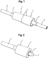
- the in the Fig. 1 shown connector comprises a first connector 1 (see. Fig. 2 and 3 ) and a second connector 2 (see. Fig. 4 and 5 ).
- Both Connectors 1, 2 each comprise a housing 3 and an at least partially disposed in the respective housing contact part 4, 5.
- Both contact parts 4, 5 have a plug-side end, which is provided for axial contact with the respective other contact part 4, 5.
- the two contact parts 4, 5, a cable-side end, which is provided in each case for connection to a conductor 6 of a cable, not shown, moreover.
- the cable-side ends of the contact parts 4, 5 are tubular, so that they can receive the conductor 6 of the associated cable end.
- a mechanical connection between the contact parts 4, 5 and the conductors 6 can be done for example by soldering, including soldering holes in the contact parts 4, 5 are provided.
- the contact part 4 of the first connector 1 has on the plug side a part-spherical end face 7. This contacts an end face of the contact part 5 of the second connector 2 in a recess 8, which is formed in a trumpet shape (in the direction of the plug-side end) widening. This results in an annular contact area between the contact parts 4, 5, which is also given when the two connectors 1, 2 or the two contact parts 4, 5 not exactly coaxial (with respect to the longitudinal axes of the circular cross-sections having contact parts 4, 5) aligned with each other.
- the connector is relatively insensitive in terms of contact reliability with respect to positional and form tolerances of the components.
- the contact part 4 of the first connector 1 is axially (ie in the directions defined by the longitudinal axis) movably mounted within the associated housing 3 and biased by a biased coil spring 9 in the direction of the second connector 2 ,
- the coil spring is supported between the circumferential Bund 10 of the contact part 4 and a mounting sleeve 12, which in the assembly of the first connector 1 of the cable-side end is pressed into the receiving opening of the housing 3, thereby ensuring the cohesion of the first connector 1.
- its contact part 5 is likewise inserted from the cable end into a centrally arranged receiving opening of the associated housing 3 and fixed there (for example by force fit by pressing in or materially by gluing).
- the in the Fig. 6 to 8 illustrated second embodiment of a connector according to the invention also has a first connector 1 and a second connector 2.
- the connector shown is the embodiment with a plurality of contact elements. Concretely, three pairs of contacting according to the invention contact elements 4, 5 are provided.
- the individual contact elements 4, 5 are the first, in the Fig. 1 to 5 shown embodiments formed and integrated in a substantially identical manner in the associated housing 3.
- the coil springs 9 acting on the contact elements 4 are not supported on fastening sleeves at the rear, but on an end face of a housing part of the multi-part housing 3.
- the contact elements 4, 5 can be provided for the transmission of high current in a high voltage circuit.
- these can be integrated into the electrical traction network of a (partially) electrified motor vehicle or into a charging system for this purpose.
- high voltage according to the invention is understood to mean an electrical voltage of at least 30 V for alternating current and at least 60 V for direct voltage.
- low voltage is meant correspondingly an electrical voltage which is less than 30 V or 60 V.
- the two connectors 1, 2 further comprise smaller dimensioned contact elements 13, which are part of a low-voltage operated Can be backup circuit, which can serve as a so-called interlock for the contact elements 4, 5 comprehensive high-voltage circuit.
Applications Claiming Priority (2)
| Application Number | Priority Date | Filing Date | Title |
|---|---|---|---|
| DE202014001590.2U DE202014001590U1 (de) | 2014-02-20 | 2014-02-20 | Steckverbindung |
| PCT/EP2015/000021 WO2015124245A1 (de) | 2014-02-20 | 2015-01-08 | Steckverbindung |
Publications (2)
| Publication Number | Publication Date |
|---|---|
| EP3108545A1 EP3108545A1 (de) | 2016-12-28 |
| EP3108545B1 true EP3108545B1 (de) | 2019-04-17 |
Family
ID=50556339
Family Applications (1)
| Application Number | Title | Priority Date | Filing Date |
|---|---|---|---|
| EP15700030.8A Active EP3108545B1 (de) | 2014-02-20 | 2015-01-08 | Steckverbindung |
Country Status (9)
| Country | Link |
|---|---|
| US (1) | US9865954B2 (ja) |
| EP (1) | EP3108545B1 (ja) |
| JP (1) | JP6411532B2 (ja) |
| KR (1) | KR20160124077A (ja) |
| CN (1) | CN106030919B (ja) |
| CA (1) | CA2933388A1 (ja) |
| DE (1) | DE202014001590U1 (ja) |
| TW (1) | TWM509452U (ja) |
| WO (1) | WO2015124245A1 (ja) |
Families Citing this family (2)
| Publication number | Priority date | Publication date | Assignee | Title |
|---|---|---|---|---|
| US11491884B2 (en) * | 2017-01-19 | 2022-11-08 | Curtis Instruments Inc. | Magnetic charger connector for wheelchair |
| CN109941139A (zh) * | 2019-04-22 | 2019-06-28 | 王言河 | 一种新能源汽车充电线 |
Family Cites Families (13)
| Publication number | Priority date | Publication date | Assignee | Title |
|---|---|---|---|---|
| DE1092533B (de) * | 1959-09-04 | 1960-11-10 | Bbc Brown Boveri & Cie | Federdruckkontakt fuer elektrische Kupplungen, insbesondere Vielfachkupplungen |
| JPH02234370A (ja) * | 1989-03-06 | 1990-09-17 | Fujitsu Ltd | 接触子 |
| US5425649A (en) * | 1989-06-13 | 1995-06-20 | General Datacomm, Inc. | Connector system having switching and testing functions using tapered spring contact elements and actuators therefor |
| US5509813A (en) * | 1994-05-20 | 1996-04-23 | Lu; Sheng N. | Joint assembly for electrically engaging a portable computer with a battery |
| DE4441303A1 (de) * | 1994-06-29 | 1996-01-04 | Vorwerk Co Interholding | Elektrische Steckverbindung |
| WO1996000994A1 (de) * | 1994-06-29 | 1996-01-11 | Vorwerk & Co. Interholding Gmbh | Elektrische steckverbindung |
| JPH0817500A (ja) * | 1994-06-30 | 1996-01-19 | Advantest Corp | Bgaic用ソケット及びこれに用いるスプリングピン |
| US6517359B1 (en) * | 1999-05-21 | 2003-02-11 | Agilent Technologies, Inc. | System and method for mating electrical connections |
| DE20002684U1 (de) * | 2000-02-10 | 2000-05-04 | Rappl Peter | Bordnetzsicherheitskupplung |
| JP4939879B2 (ja) * | 2006-09-13 | 2012-05-30 | 株式会社エンプラス | 電気接触子、及び、電気部品用ソケット |
| JP2012022826A (ja) * | 2010-07-13 | 2012-02-02 | Japan Aviation Electronics Industry Ltd | ソケットコンタクト |
| JP5711574B2 (ja) * | 2011-03-04 | 2015-05-07 | 矢崎総業株式会社 | コネクタ |
| DE202011107900U1 (de) | 2011-11-15 | 2011-11-28 | Rosenberger Hochfrequenztechnik Gmbh & Co. Kg | Steckverbinder |
-
2014
- 2014-02-20 DE DE202014001590.2U patent/DE202014001590U1/de not_active Expired - Lifetime
-
2015
- 2015-01-08 JP JP2016552995A patent/JP6411532B2/ja active Active
- 2015-01-08 KR KR1020167017267A patent/KR20160124077A/ko not_active Application Discontinuation
- 2015-01-08 CN CN201580009276.9A patent/CN106030919B/zh active Active
- 2015-01-08 WO PCT/EP2015/000021 patent/WO2015124245A1/de active Application Filing
- 2015-01-08 US US15/119,462 patent/US9865954B2/en active Active
- 2015-01-08 EP EP15700030.8A patent/EP3108545B1/de active Active
- 2015-01-08 CA CA2933388A patent/CA2933388A1/en not_active Abandoned
- 2015-01-16 TW TW104200792U patent/TWM509452U/zh not_active IP Right Cessation
Non-Patent Citations (1)
| Title |
|---|
| None * |
Also Published As
| Publication number | Publication date |
|---|---|
| US9865954B2 (en) | 2018-01-09 |
| DE202014001590U1 (de) | 2014-04-07 |
| CN106030919A (zh) | 2016-10-12 |
| CN106030919B (zh) | 2019-09-03 |
| US20170012380A1 (en) | 2017-01-12 |
| EP3108545A1 (de) | 2016-12-28 |
| JP2017506422A (ja) | 2017-03-02 |
| TWM509452U (zh) | 2015-09-21 |
| JP6411532B2 (ja) | 2018-10-24 |
| KR20160124077A (ko) | 2016-10-26 |
| WO2015124245A1 (de) | 2015-08-27 |
| CA2933388A1 (en) | 2015-08-27 |
Similar Documents
| Publication | Publication Date | Title |
|---|---|---|
| EP2831957B1 (de) | Sicherungssystem für hochstromanwendungen | |
| EP1730815B1 (de) | Koaxialsteckverbindung für leiterplatten mit gefedertem toleranzausgleich | |
| EP2599165B1 (de) | Hochstromsteckverbinder | |
| WO2014023386A1 (de) | Steckverbinder | |
| WO2014023383A1 (de) | Steckverbinder | |
| WO2012000597A1 (de) | STECKVERBINDER MIT AUßENLEITERSCHIRM | |
| DE102015105088B4 (de) | Hochfrequenz-Winkelstecker | |
| DE102014103864A1 (de) | Steckvorrichtungsmontage in Elektrofahrzeugen | |
| EP2973887A1 (de) | Steckverbinder | |
| EP3203591B1 (de) | Steckverbinder | |
| EP3108545B1 (de) | Steckverbindung | |
| WO2012072737A1 (de) | Ladekabelseitiges steckerteil einer elektrischen steckvorrichtung eines fahrzeugs | |
| DE102007042194A1 (de) | Elektrisches Steckverbinderelement | |
| DE10261521B3 (de) | Hochstromführende Kontaktelemente mit Versatzausgleich | |
| EP1091457B1 (de) | Elektrisches Steckverbindungselement und -system | |
| DE102019114262B3 (de) | Steckverbinder mit Verriegelungssystem | |
| DE102013012693B4 (de) | Drehkupplung zur Übertragung von elektrischen Signal- und/oder Leistungsströmen | |
| EP3989368A1 (de) | Elektrischer steckverbinder, verbindungselement und leiterplattenanordnung | |
| EP2697869B1 (de) | Steckverbinder mit einem kontaktelement | |
| WO2016166066A1 (de) | Elektrische steckverbindung und verfahren zum lösen einer elektrischen steckverbindung | |
| EP1720222A2 (de) | Steckverbinder, insbesondere für Airbag-Zündsysteme | |
| EP2192658B1 (de) | Verbindungseinrichtung | |
| DE102009031031A1 (de) | Elektrische Steckverbindungseinrichtung | |
| DE102020204794A1 (de) | elektrische Steckverbindung | |
| AT504142A4 (de) | Elektrisches kabel mit an beiden kabelenden montierten kabelsteckverbindern |
Legal Events
| Date | Code | Title | Description |
|---|---|---|---|
| PUAI | Public reference made under article 153(3) epc to a published international application that has entered the european phase |
Free format text: ORIGINAL CODE: 0009012 |
|
| STAA | Information on the status of an ep patent application or granted ep patent |
Free format text: STATUS: REQUEST FOR EXAMINATION WAS MADE |
|
| 17P | Request for examination filed |
Effective date: 20160609 |
|
| AK | Designated contracting states |
Kind code of ref document: A1 Designated state(s): AL AT BE BG CH CY CZ DE DK EE ES FI FR GB GR HR HU IE IS IT LI LT LU LV MC MK MT NL NO PL PT RO RS SE SI SK SM TR |
|
| AX | Request for extension of the european patent |
Extension state: BA ME |
|
| DAX | Request for extension of the european patent (deleted) | ||
| GRAP | Despatch of communication of intention to grant a patent |
Free format text: ORIGINAL CODE: EPIDOSNIGR1 |
|
| STAA | Information on the status of an ep patent application or granted ep patent |
Free format text: STATUS: GRANT OF PATENT IS INTENDED |
|
| INTG | Intention to grant announced |
Effective date: 20180910 |
|
| GRAS | Grant fee paid |
Free format text: ORIGINAL CODE: EPIDOSNIGR3 |
|
| GRAA | (expected) grant |
Free format text: ORIGINAL CODE: 0009210 |
|
| STAA | Information on the status of an ep patent application or granted ep patent |
Free format text: STATUS: THE PATENT HAS BEEN GRANTED |
|
| AK | Designated contracting states |
Kind code of ref document: B1 Designated state(s): AL AT BE BG CH CY CZ DE DK EE ES FI FR GB GR HR HU IE IS IT LI LT LU LV MC MK MT NL NO PL PT RO RS SE SI SK SM TR |
|
| REG | Reference to a national code |
Ref country code: GB Ref legal event code: FG4D Free format text: NOT ENGLISH |
|
| REG | Reference to a national code |
Ref country code: CH Ref legal event code: EP |
|
| REG | Reference to a national code |
Ref country code: DE Ref legal event code: R096 Ref document number: 502015008721 Country of ref document: DE |
|
| REG | Reference to a national code |
Ref country code: AT Ref legal event code: REF Ref document number: 1122595 Country of ref document: AT Kind code of ref document: T Effective date: 20190515 Ref country code: IE Ref legal event code: FG4D Free format text: LANGUAGE OF EP DOCUMENT: GERMAN |
|
| REG | Reference to a national code |
Ref country code: SE Ref legal event code: TRGR |
|
| REG | Reference to a national code |
Ref country code: NL Ref legal event code: MP Effective date: 20190417 |
|
| REG | Reference to a national code |
Ref country code: LT Ref legal event code: MG4D |
|
| PG25 | Lapsed in a contracting state [announced via postgrant information from national office to epo] |
Ref country code: NL Free format text: LAPSE BECAUSE OF FAILURE TO SUBMIT A TRANSLATION OF THE DESCRIPTION OR TO PAY THE FEE WITHIN THE PRESCRIBED TIME-LIMIT Effective date: 20190417 |
|
| PG25 | Lapsed in a contracting state [announced via postgrant information from national office to epo] |
Ref country code: HR Free format text: LAPSE BECAUSE OF FAILURE TO SUBMIT A TRANSLATION OF THE DESCRIPTION OR TO PAY THE FEE WITHIN THE PRESCRIBED TIME-LIMIT Effective date: 20190417 Ref country code: LT Free format text: LAPSE BECAUSE OF FAILURE TO SUBMIT A TRANSLATION OF THE DESCRIPTION OR TO PAY THE FEE WITHIN THE PRESCRIBED TIME-LIMIT Effective date: 20190417 Ref country code: FI Free format text: LAPSE BECAUSE OF FAILURE TO SUBMIT A TRANSLATION OF THE DESCRIPTION OR TO PAY THE FEE WITHIN THE PRESCRIBED TIME-LIMIT Effective date: 20190417 Ref country code: NO Free format text: LAPSE BECAUSE OF FAILURE TO SUBMIT A TRANSLATION OF THE DESCRIPTION OR TO PAY THE FEE WITHIN THE PRESCRIBED TIME-LIMIT Effective date: 20190717 Ref country code: AL Free format text: LAPSE BECAUSE OF FAILURE TO SUBMIT A TRANSLATION OF THE DESCRIPTION OR TO PAY THE FEE WITHIN THE PRESCRIBED TIME-LIMIT Effective date: 20190417 Ref country code: PT Free format text: LAPSE BECAUSE OF FAILURE TO SUBMIT A TRANSLATION OF THE DESCRIPTION OR TO PAY THE FEE WITHIN THE PRESCRIBED TIME-LIMIT Effective date: 20190817 Ref country code: ES Free format text: LAPSE BECAUSE OF FAILURE TO SUBMIT A TRANSLATION OF THE DESCRIPTION OR TO PAY THE FEE WITHIN THE PRESCRIBED TIME-LIMIT Effective date: 20190417 |
|
| PG25 | Lapsed in a contracting state [announced via postgrant information from national office to epo] |
Ref country code: BG Free format text: LAPSE BECAUSE OF FAILURE TO SUBMIT A TRANSLATION OF THE DESCRIPTION OR TO PAY THE FEE WITHIN THE PRESCRIBED TIME-LIMIT Effective date: 20190717 Ref country code: GR Free format text: LAPSE BECAUSE OF FAILURE TO SUBMIT A TRANSLATION OF THE DESCRIPTION OR TO PAY THE FEE WITHIN THE PRESCRIBED TIME-LIMIT Effective date: 20190718 Ref country code: RS Free format text: LAPSE BECAUSE OF FAILURE TO SUBMIT A TRANSLATION OF THE DESCRIPTION OR TO PAY THE FEE WITHIN THE PRESCRIBED TIME-LIMIT Effective date: 20190417 Ref country code: LV Free format text: LAPSE BECAUSE OF FAILURE TO SUBMIT A TRANSLATION OF THE DESCRIPTION OR TO PAY THE FEE WITHIN THE PRESCRIBED TIME-LIMIT Effective date: 20190417 Ref country code: PL Free format text: LAPSE BECAUSE OF FAILURE TO SUBMIT A TRANSLATION OF THE DESCRIPTION OR TO PAY THE FEE WITHIN THE PRESCRIBED TIME-LIMIT Effective date: 20190417 |
|
| PG25 | Lapsed in a contracting state [announced via postgrant information from national office to epo] |
Ref country code: IS Free format text: LAPSE BECAUSE OF FAILURE TO SUBMIT A TRANSLATION OF THE DESCRIPTION OR TO PAY THE FEE WITHIN THE PRESCRIBED TIME-LIMIT Effective date: 20190817 |
|
| REG | Reference to a national code |
Ref country code: DE Ref legal event code: R097 Ref document number: 502015008721 Country of ref document: DE |
|
| PG25 | Lapsed in a contracting state [announced via postgrant information from national office to epo] |
Ref country code: EE Free format text: LAPSE BECAUSE OF FAILURE TO SUBMIT A TRANSLATION OF THE DESCRIPTION OR TO PAY THE FEE WITHIN THE PRESCRIBED TIME-LIMIT Effective date: 20190417 Ref country code: SK Free format text: LAPSE BECAUSE OF FAILURE TO SUBMIT A TRANSLATION OF THE DESCRIPTION OR TO PAY THE FEE WITHIN THE PRESCRIBED TIME-LIMIT Effective date: 20190417 Ref country code: DK Free format text: LAPSE BECAUSE OF FAILURE TO SUBMIT A TRANSLATION OF THE DESCRIPTION OR TO PAY THE FEE WITHIN THE PRESCRIBED TIME-LIMIT Effective date: 20190417 Ref country code: RO Free format text: LAPSE BECAUSE OF FAILURE TO SUBMIT A TRANSLATION OF THE DESCRIPTION OR TO PAY THE FEE WITHIN THE PRESCRIBED TIME-LIMIT Effective date: 20190417 Ref country code: CZ Free format text: LAPSE BECAUSE OF FAILURE TO SUBMIT A TRANSLATION OF THE DESCRIPTION OR TO PAY THE FEE WITHIN THE PRESCRIBED TIME-LIMIT Effective date: 20190417 |
|
| PLBE | No opposition filed within time limit |
Free format text: ORIGINAL CODE: 0009261 |
|
| STAA | Information on the status of an ep patent application or granted ep patent |
Free format text: STATUS: NO OPPOSITION FILED WITHIN TIME LIMIT |
|
| PG25 | Lapsed in a contracting state [announced via postgrant information from national office to epo] |
Ref country code: SM Free format text: LAPSE BECAUSE OF FAILURE TO SUBMIT A TRANSLATION OF THE DESCRIPTION OR TO PAY THE FEE WITHIN THE PRESCRIBED TIME-LIMIT Effective date: 20190417 |
|
| 26N | No opposition filed |
Effective date: 20200120 |
|
| PG25 | Lapsed in a contracting state [announced via postgrant information from national office to epo] |
Ref country code: TR Free format text: LAPSE BECAUSE OF FAILURE TO SUBMIT A TRANSLATION OF THE DESCRIPTION OR TO PAY THE FEE WITHIN THE PRESCRIBED TIME-LIMIT Effective date: 20190417 |
|
| PG25 | Lapsed in a contracting state [announced via postgrant information from national office to epo] |
Ref country code: SI Free format text: LAPSE BECAUSE OF FAILURE TO SUBMIT A TRANSLATION OF THE DESCRIPTION OR TO PAY THE FEE WITHIN THE PRESCRIBED TIME-LIMIT Effective date: 20190417 |
|
| PG25 | Lapsed in a contracting state [announced via postgrant information from national office to epo] |
Ref country code: MC Free format text: LAPSE BECAUSE OF FAILURE TO SUBMIT A TRANSLATION OF THE DESCRIPTION OR TO PAY THE FEE WITHIN THE PRESCRIBED TIME-LIMIT Effective date: 20190417 |
|
| REG | Reference to a national code |
Ref country code: CH Ref legal event code: PL |
|
| REG | Reference to a national code |
Ref country code: BE Ref legal event code: MM Effective date: 20200131 |
|
| PG25 | Lapsed in a contracting state [announced via postgrant information from national office to epo] |
Ref country code: LU Free format text: LAPSE BECAUSE OF NON-PAYMENT OF DUE FEES Effective date: 20200108 |
|
| PG25 | Lapsed in a contracting state [announced via postgrant information from national office to epo] |
Ref country code: BE Free format text: LAPSE BECAUSE OF NON-PAYMENT OF DUE FEES Effective date: 20200131 Ref country code: LI Free format text: LAPSE BECAUSE OF NON-PAYMENT OF DUE FEES Effective date: 20200131 Ref country code: CH Free format text: LAPSE BECAUSE OF NON-PAYMENT OF DUE FEES Effective date: 20200131 |
|
| PG25 | Lapsed in a contracting state [announced via postgrant information from national office to epo] |
Ref country code: IE Free format text: LAPSE BECAUSE OF NON-PAYMENT OF DUE FEES Effective date: 20200108 |
|
| REG | Reference to a national code |
Ref country code: AT Ref legal event code: MM01 Ref document number: 1122595 Country of ref document: AT Kind code of ref document: T Effective date: 20200108 |
|
| PG25 | Lapsed in a contracting state [announced via postgrant information from national office to epo] |
Ref country code: AT Free format text: LAPSE BECAUSE OF NON-PAYMENT OF DUE FEES Effective date: 20200108 |
|
| PG25 | Lapsed in a contracting state [announced via postgrant information from national office to epo] |
Ref country code: MT Free format text: LAPSE BECAUSE OF FAILURE TO SUBMIT A TRANSLATION OF THE DESCRIPTION OR TO PAY THE FEE WITHIN THE PRESCRIBED TIME-LIMIT Effective date: 20190417 Ref country code: CY Free format text: LAPSE BECAUSE OF FAILURE TO SUBMIT A TRANSLATION OF THE DESCRIPTION OR TO PAY THE FEE WITHIN THE PRESCRIBED TIME-LIMIT Effective date: 20190417 |
|
| PG25 | Lapsed in a contracting state [announced via postgrant information from national office to epo] |
Ref country code: MK Free format text: LAPSE BECAUSE OF FAILURE TO SUBMIT A TRANSLATION OF THE DESCRIPTION OR TO PAY THE FEE WITHIN THE PRESCRIBED TIME-LIMIT Effective date: 20190417 |
|
| PGFP | Annual fee paid to national office [announced via postgrant information from national office to epo] |
Ref country code: FR Payment date: 20230124 Year of fee payment: 9 |
|
| PGFP | Annual fee paid to national office [announced via postgrant information from national office to epo] |
Ref country code: SE Payment date: 20230124 Year of fee payment: 9 Ref country code: IT Payment date: 20230120 Year of fee payment: 9 Ref country code: GB Payment date: 20230124 Year of fee payment: 9 Ref country code: DE Payment date: 20230127 Year of fee payment: 9 |
|
| P01 | Opt-out of the competence of the unified patent court (upc) registered |
Effective date: 20230527 |
|
| REG | Reference to a national code |
Ref country code: DE Ref legal event code: R082 Ref document number: 502015008721 Country of ref document: DE Representative=s name: KANDLBINDER, MARKUS, DIPL.-PHYS., DE |