EP3108545B1 - Plug connection - Google Patents
Plug connection Download PDFInfo
- Publication number
- EP3108545B1 EP3108545B1 EP15700030.8A EP15700030A EP3108545B1 EP 3108545 B1 EP3108545 B1 EP 3108545B1 EP 15700030 A EP15700030 A EP 15700030A EP 3108545 B1 EP3108545 B1 EP 3108545B1
- Authority
- EP
- European Patent Office
- Prior art keywords
- contact
- connector
- contact part
- housing
- plug
- Prior art date
- Legal status (The legal status is an assumption and is not a legal conclusion. Google has not performed a legal analysis and makes no representation as to the accuracy of the status listed.)
- Active
Links
- 230000013011 mating Effects 0.000 description 5
- 239000004020 conductor Substances 0.000 description 3
- 230000005540 biological transmission Effects 0.000 description 2
- 238000005476 soldering Methods 0.000 description 2
- 238000004026 adhesive bonding Methods 0.000 description 1
- 230000001419 dependent effect Effects 0.000 description 1
- 238000003780 insertion Methods 0.000 description 1
- 230000037431 insertion Effects 0.000 description 1
- 238000004519 manufacturing process Methods 0.000 description 1
- 238000003825 pressing Methods 0.000 description 1
- 238000003860 storage Methods 0.000 description 1
- 238000004804 winding Methods 0.000 description 1
Images


Classifications
-
- H—ELECTRICITY
- H01—ELECTRIC ELEMENTS
- H01R—ELECTRICALLY-CONDUCTIVE CONNECTIONS; STRUCTURAL ASSOCIATIONS OF A PLURALITY OF MUTUALLY-INSULATED ELECTRICAL CONNECTING ELEMENTS; COUPLING DEVICES; CURRENT COLLECTORS
- H01R13/00—Details of coupling devices of the kinds covered by groups H01R12/70 or H01R24/00 - H01R33/00
- H01R13/02—Contact members
- H01R13/15—Pins, blades or sockets having separate spring member for producing or increasing contact pressure
- H01R13/187—Pins, blades or sockets having separate spring member for producing or increasing contact pressure with spring member in the socket
-
- H—ELECTRICITY
- H01—ELECTRIC ELEMENTS
- H01R—ELECTRICALLY-CONDUCTIVE CONNECTIONS; STRUCTURAL ASSOCIATIONS OF A PLURALITY OF MUTUALLY-INSULATED ELECTRICAL CONNECTING ELEMENTS; COUPLING DEVICES; CURRENT COLLECTORS
- H01R13/00—Details of coupling devices of the kinds covered by groups H01R12/70 or H01R24/00 - H01R33/00
- H01R13/02—Contact members
- H01R13/22—Contacts for co-operating by abutting
- H01R13/24—Contacts for co-operating by abutting resilient; resiliently-mounted
- H01R13/2407—Contacts for co-operating by abutting resilient; resiliently-mounted characterized by the resilient means
- H01R13/2421—Contacts for co-operating by abutting resilient; resiliently-mounted characterized by the resilient means using coil springs
-
- H—ELECTRICITY
- H01—ELECTRIC ELEMENTS
- H01R—ELECTRICALLY-CONDUCTIVE CONNECTIONS; STRUCTURAL ASSOCIATIONS OF A PLURALITY OF MUTUALLY-INSULATED ELECTRICAL CONNECTING ELEMENTS; COUPLING DEVICES; CURRENT COLLECTORS
- H01R13/00—Details of coupling devices of the kinds covered by groups H01R12/70 or H01R24/00 - H01R33/00
- H01R13/02—Contact members
- H01R13/22—Contacts for co-operating by abutting
- H01R13/24—Contacts for co-operating by abutting resilient; resiliently-mounted
- H01R13/2464—Contacts for co-operating by abutting resilient; resiliently-mounted characterized by the contact point
-
- H—ELECTRICITY
- H01—ELECTRIC ELEMENTS
- H01R—ELECTRICALLY-CONDUCTIVE CONNECTIONS; STRUCTURAL ASSOCIATIONS OF A PLURALITY OF MUTUALLY-INSULATED ELECTRICAL CONNECTING ELEMENTS; COUPLING DEVICES; CURRENT COLLECTORS
- H01R13/00—Details of coupling devices of the kinds covered by groups H01R12/70 or H01R24/00 - H01R33/00
- H01R13/46—Bases; Cases
- H01R13/53—Bases or cases for heavy duty; Bases or cases for high voltage with means for preventing corona or arcing
-
- H—ELECTRICITY
- H01—ELECTRIC ELEMENTS
- H01R—ELECTRICALLY-CONDUCTIVE CONNECTIONS; STRUCTURAL ASSOCIATIONS OF A PLURALITY OF MUTUALLY-INSULATED ELECTRICAL CONNECTING ELEMENTS; COUPLING DEVICES; CURRENT COLLECTORS
- H01R2201/00—Connectors or connections adapted for particular applications
- H01R2201/26—Connectors or connections adapted for particular applications for vehicles
Definitions
- the invention relates to a connector and in particular a connector for connecting high-current lines, such as those used in or for motor vehicles with electric traction drives, having a first contact part having a first connector and a second contact part having second connector, wherein the contact parts in the assembled state the spring-loaded connector contact axially, wherein the first contact part has a three-dimensionally curved end face and the second contact part has a widening recess in its end face, so that there is an annular contact area between the contact parts, according to the preamble of claim 1.
- the backup circuit is integrated into a control system for the high voltage source, the control system, the high voltage source is activated only when the backup circuit is closed due to a contacting of the contact elements of the connector.
- the connectors are designed such that when plugging the connector first contact the contact parts connected to the high current lines and then only the contact elements for the backup circuit.
- the contact elements of the backup circuit are first solved, whereby - if not already done - a Hochnapssbeaufschlagung the high current lines is interrupted. Only then are the contact parts connected to the high current lines out of contact.
- a corresponding connector is for example from the DE 20 2011 107 900 U1 known.
- the contact parts are designed as simple contact pins and contact sockets, which are plugged into each other when mating the connector.
- Such an embodiment of the contact elements of the fuse circuit requires a mating of the connector in an exact alignment with each other, whereby the handling is difficult.
- a generic connector is from the EP 0 836 245 A2 known which has an electrical connector with a plug receptacle and a in Cross-section round connector pin covered.
- the plug receptacle on a receiving chamber, wherein in the receiving chamber a compressible in the axial direction, individual turns having coil spring is arranged, wherein the turns predominantly have a same major diameter.
- the main diameter of the coil spring is greater than an outer diameter of the connector pin and that one or a few contact windings a relative to the main diameter of the coil spring have smaller contact diameter, which is also smaller than the outer diameter of the connector pin.
- the present invention seeks to improve a particular intended for high voltage applications in or for motor vehicles connector.
- the connector should be characterized by easy handling when mating, secure contact and / or low manufacturing costs.
- the depression widens in a trumpet shape in the direction of the plug-side end of the second contact part.
- the first and / or second contact part has a radial mobility at least in the area of the end face serving as a contact surface for example, by a corresponding storage in a housing of the associated connector can be realized.
- the radial mobility can also be achieved by pivoting about an axis perpendicular to the longitudinal axis of the corresponding contact part.
- the resulting possibly resulting coaxiality or parallelism of the longitudinal axes of the two contacting contact parts does not present a relevant problem for the contact reliability because of the particular configuration of the contacting end faces.
- a further advantage of the plug connection according to the invention can result from the fact that no filigree components are provided in the contact area are. At least from the point of view of component protection, therefore, it may be possible to dispense with an interlock fuse circuit and design the plug-in connection in the case of the preferably provided high-current applications as so-called hot-pluggable.
- the end face of the first contact part can be part-spherical (that is, part-spherical).
- Such an embodiment of the end face of the first contact part in particular in conjunction with a likewise preferred trumpet-shaped embodiment of the recess of the second contact part, can be characterized by a good Aerozentri mecanicsfunktion gleich and a particularly good insensitivity to Brockkoaxiali decisiv or non-parallelism of the longitudinal axes of the contact parts.
- each of the plug connectors has a housing receiving the associated contact part.
- at least one of the contact parts is spring-loaded axially displaceably mounted in the associated housing. This can represent a structurally simple realization of the axial spring load of the contact area formed between the contact parts.
- the spring load of the contact region can then be realized preferably by means of a coil spring surrounding the axially displaceable contact part, which extends between a section, for example an outer circumferential part Bearing of the contact part and a portion, for example, an inner circumferential collar of the housing is supported.
- a coil spring surrounding the axially displaceable contact part, which extends between a section, for example an outer circumferential part Bearing of the contact part and a portion, for example, an inner circumferential collar of the housing is supported.
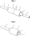
- the in the Fig. 1 shown connector comprises a first connector 1 (see. Fig. 2 and 3 ) and a second connector 2 (see. Fig. 4 and 5 ).
- Both Connectors 1, 2 each comprise a housing 3 and an at least partially disposed in the respective housing contact part 4, 5.
- Both contact parts 4, 5 have a plug-side end, which is provided for axial contact with the respective other contact part 4, 5.
- the two contact parts 4, 5, a cable-side end, which is provided in each case for connection to a conductor 6 of a cable, not shown, moreover.
- the cable-side ends of the contact parts 4, 5 are tubular, so that they can receive the conductor 6 of the associated cable end.
- a mechanical connection between the contact parts 4, 5 and the conductors 6 can be done for example by soldering, including soldering holes in the contact parts 4, 5 are provided.
- the contact part 4 of the first connector 1 has on the plug side a part-spherical end face 7. This contacts an end face of the contact part 5 of the second connector 2 in a recess 8, which is formed in a trumpet shape (in the direction of the plug-side end) widening. This results in an annular contact area between the contact parts 4, 5, which is also given when the two connectors 1, 2 or the two contact parts 4, 5 not exactly coaxial (with respect to the longitudinal axes of the circular cross-sections having contact parts 4, 5) aligned with each other.
- the connector is relatively insensitive in terms of contact reliability with respect to positional and form tolerances of the components.
- the contact part 4 of the first connector 1 is axially (ie in the directions defined by the longitudinal axis) movably mounted within the associated housing 3 and biased by a biased coil spring 9 in the direction of the second connector 2 ,
- the coil spring is supported between the circumferential Bund 10 of the contact part 4 and a mounting sleeve 12, which in the assembly of the first connector 1 of the cable-side end is pressed into the receiving opening of the housing 3, thereby ensuring the cohesion of the first connector 1.
- its contact part 5 is likewise inserted from the cable end into a centrally arranged receiving opening of the associated housing 3 and fixed there (for example by force fit by pressing in or materially by gluing).
- the in the Fig. 6 to 8 illustrated second embodiment of a connector according to the invention also has a first connector 1 and a second connector 2.
- the connector shown is the embodiment with a plurality of contact elements. Concretely, three pairs of contacting according to the invention contact elements 4, 5 are provided.
- the individual contact elements 4, 5 are the first, in the Fig. 1 to 5 shown embodiments formed and integrated in a substantially identical manner in the associated housing 3.
- the coil springs 9 acting on the contact elements 4 are not supported on fastening sleeves at the rear, but on an end face of a housing part of the multi-part housing 3.
- the contact elements 4, 5 can be provided for the transmission of high current in a high voltage circuit.
- these can be integrated into the electrical traction network of a (partially) electrified motor vehicle or into a charging system for this purpose.
- high voltage according to the invention is understood to mean an electrical voltage of at least 30 V for alternating current and at least 60 V for direct voltage.
- low voltage is meant correspondingly an electrical voltage which is less than 30 V or 60 V.
- the two connectors 1, 2 further comprise smaller dimensioned contact elements 13, which are part of a low-voltage operated Can be backup circuit, which can serve as a so-called interlock for the contact elements 4, 5 comprehensive high-voltage circuit.
Landscapes
- Details Of Connecting Devices For Male And Female Coupling (AREA)
Description
Die Erfindung betrifft eine Steckverbindung und insbesondere eine Steckverbindung zur Verbindung von Hochstromleitungen, wie sie beispielsweise in oder für Kraftfahrzeuge mit elektrischen Fahrantrieben eingesetzt werden, mit einem ein erstes Kontaktteil aufweisenden ersten Steckverbinder und einem ein zweites Kontaktteil aufweisenden zweiten Steckverbinder, wobei die Kontaktteile im zusammengesteckten Zustand der Steckverbindung federbelastet axial kontaktieren, wobei das erste Kontaktteil eine dreidimensional gekrümmte Stirnfläche und das zweite Kontaktteil eine sich aufweitende Vertiefung in seiner Stirnfläche aufweist, so dass sich ein ringförmiger Kontaktbereich zwischen den Kontaktteilen ergibt, gemäß dem Oberbegriff von Anspruch 1.The invention relates to a connector and in particular a connector for connecting high-current lines, such as those used in or for motor vehicles with electric traction drives, having a first contact part having a first connector and a second contact part having second connector, wherein the contact parts in the assembled state the spring-loaded connector contact axially, wherein the first contact part has a three-dimensionally curved end face and the second contact part has a widening recess in its end face, so that there is an annular contact area between the contact parts, according to the preamble of
An Steckverbindungen, die zur Verbindung von Hochstromleitungen in beispielsweise Kraftfahrzeugen eingesetzt werden, werden besondere Anforderungen gestellt. Diese sind unter anderem für die Sicherheit des die Steckverbinder zusammensteckenden beziehungsweise lösenden Montagepersonals sowie für den Schutz der im Kraftfahrzeug verbauten elektronischen Komponenten relevant. So ist beispielsweise vorgesehen, neben den für die Übertragung des Hochstroms vorgesehenen, regelmäßig mit großem Querschnitt dimensionierten Kontaktteilen noch zusätzliche Kontaktelemente in die Steckverbinder zu integrieren, die von den Kontaktteilen elektrisch isoliert und Teil eines mit Niederspannung (insbesondere 12 V, 24 V oder 48 V des Bordnetzes des Kraftfahrzeugs) beaufschlagten Sicherungsstromkreises sind. Mittels des Sicherungsstromkreises soll gewährleistet werden, dass die Kontaktteile der Steckverbinder erst dann mit der Hochspannung beaufschlagt werden, wenn diese vollständig kontaktieren. Der Sicherungsstromkreis ist dazu in ein Steuerungssystem für die Hochspannungsquelle integriert, wobei das Steuerungssystem die Hochspannungsquelle erst aktiviert, wenn der Sicherungsstromkreis infolge einer Kontaktierung der Kontaktelemente der Steckverbindung geschlossen ist. Hierzu sind die Steckverbinder derart ausgebildet, dass beim Zusammenstecken der Steckverbinder zunächst die mit den Hochstromleitungen verbundenen Kontaktteile und dann erst die Kontaktelemente für den Sicherungsstromkreis kontaktieren. Beim Lösen werden zunächst die Kontaktelemente des Sicherungsstromkreises gelöst, wodurch - sofern nicht bereits erfolgt - eine Hochspannungsbeaufschlagung der Hochstromleitungen unterbrochen wird. Dann erst werden die mit den Hochstromleitungen verbundenen Kontaktteile außer Kontakt gebracht. Dadurch kann ein Überschlag beim Zusammenstecken bzw. Lösen der Steckverbindung infolge anliegender Hochspannung, der zu einer Verletzung des Montagepersonals und zu einem Verbrennen der Kontaktteile führen könnte, vermieden werden. Eine solche Sicherungsfunktionalität wird vielfach auch mit dem Begriff "Interlock" bezeichnet.At plug connections, which are used for the connection of high-current lines in for example motor vehicles, special requirements are made. These are relevant, inter alia, for the safety of the assembly personnel plugging together or loosening as well as for the protection of the electronic components installed in the motor vehicle. Thus, for example, in addition to the measures provided for the transmission of the high current, regularly dimensioned with a large cross section contact parts nor additional contact elements in the To integrate connectors that are electrically isolated from the contact parts and part of a low voltage (in particular 12 V, 24 V or 48 V of the electrical system of the motor vehicle) acted upon backup circuit. By means of the fuse circuit is to ensure that the contact parts of the connector are only then applied to the high voltage when they contact completely. The backup circuit is integrated into a control system for the high voltage source, the control system, the high voltage source is activated only when the backup circuit is closed due to a contacting of the contact elements of the connector. For this purpose, the connectors are designed such that when plugging the connector first contact the contact parts connected to the high current lines and then only the contact elements for the backup circuit. When releasing the contact elements of the backup circuit are first solved, whereby - if not already done - a Hochspannungsbeaufschlagung the high current lines is interrupted. Only then are the contact parts connected to the high current lines out of contact. As a result, a rollover during mating or loosening of the connector as a result of applied high voltage, which could lead to a violation of the assembly personnel and to a burning of the contact parts, can be avoided. Such a backup functionality is often referred to by the term "interlock".
Eine entsprechende Steckverbindung ist beispielsweise aus der
Eine solche Ausgestaltung der Kontaktelemente des Sicherungsstromkreises erfordert ein Zusammenstecken der Steckverbinder in einer exakten Ausrichtung zueinander, wodurch die Handhabung erschwert wird.Such an embodiment of the contact elements of the fuse circuit requires a mating of the connector in an exact alignment with each other, whereby the handling is difficult.
Eine gattungsgemäße Steckverbindung ist aus der
Ausgehend von diesem Stand der Technik lag der Erfindung die Aufgabe zugrunde, eine insbesondere für Hochspannungsanwendungen in oder für Kraftfahrzeuge vorgesehene Steckverbindung zu verbessern. Insbesondere sollte sich die Steckverbindung durch eine einfache Handhabung beim Zusammenstecken, eine sichere Kontaktierung und/oder geringe Herstellungskosten auszeichnen.Based on this prior art, the present invention seeks to improve a particular intended for high voltage applications in or for motor vehicles connector. In particular, the connector should be characterized by easy handling when mating, secure contact and / or low manufacturing costs.
Diese Aufgabe wird durch eine Steckverbindung der o.g. Art mit den in Anspruch 1 gekennzeichneten Merkmalen gelöst. Vorteilhafte Ausgestaltungen davon sind Gegenstand der abhängigen Ansprüche und ergeben sich aus der nachfolgenden Beschreibung der Erfindung.This task is performed by a plug-in of the o.g. Art solved with the features characterized in
Bei einer Steckverbindung der o.g Art ist es erfindungsgemäß vorgesene, dass die Vertiefung sich trompetenförmig in Richtung zum steckseitigen Ende des zweiten Kontaktteils aufweitet.In a plug connection of the above-mentioned type, it is inventively provided that the depression widens in a trumpet shape in the direction of the plug-side end of the second contact part.
Dies hat den Vorteil, dass die besondere Ausgestaltung der Stirnflächen des ersten und zweiten Kontaktteils für eine Selbstzentrierung der Kontaktteile bezüglich ihrer Längsachsen sorgt.This has the advantage that the special configuration of the end faces of the first and second contact part ensures self-centering of the contact parts with respect to their longitudinal axes.
Um dies zu unterstützen kann in einer bevorzugten Ausgestaltung vorgesehen sein, dass das erste und/oder zweite Kontaktteil zumindest im Bereich der als Kontaktfläche dienenden Stirnfläche eine radiale Beweglichkeit aufweist, die beispielsweise durch eine entsprechende Lagerung in einem Gehäuse des dazugehörigen Steckverbinders realisiert werden kann. Dabei kann die radiale Beweglichkeit auch durch ein Verschwenken um eine zur Längsachse des entsprechenden Kontaktteils senkrechte Achse erzielt werden. Die sich daraus gegebenenfalls ergebende fehlende Koaxialität oder Parallelität der Längsachsen der zwei kontaktierenden Kontaktteile stellt dabei wegen der besonderen Ausgestaltung der kontaktierenden Stirnflächen kein relevantes Problem für die Kontaktsicherheit dar. Ein weiterer Vorteil der erfindungsgemäßen Steckverbindung kann sich daraus ergeben, dass im Kontaktbereich keine filigranen Bauteile vorgesehen sind. Zumindest aus Sicht des Bauteilschutzes kann daher gegebenenfalls auf einen Interlock-Sicherungskreis verzichtet werden und die Steckverbindung bei den bevorzugt vorgesehenen Hochstromanwendungen als sogenannt Hot-Plug-fähig ausgestaltet werden.To support this, it can be provided in a preferred embodiment that the first and / or second contact part has a radial mobility at least in the area of the end face serving as a contact surface for example, by a corresponding storage in a housing of the associated connector can be realized. In this case, the radial mobility can also be achieved by pivoting about an axis perpendicular to the longitudinal axis of the corresponding contact part. The resulting possibly resulting coaxiality or parallelism of the longitudinal axes of the two contacting contact parts does not present a relevant problem for the contact reliability because of the particular configuration of the contacting end faces. A further advantage of the plug connection according to the invention can result from the fact that no filigree components are provided in the contact area are. At least from the point of view of component protection, therefore, it may be possible to dispense with an interlock fuse circuit and design the plug-in connection in the case of the preferably provided high-current applications as so-called hot-pluggable.
In einer bevorzugten Ausgestaltung der erfindungsgemäßen Steckverbindung kann vorgesehen sein, dass die Stirnfläche des ersten Kontaktteils teilsphärisch (d.h. teilkugelförmig) ist. Eine solche Ausgestaltung der Stirnfläche des ersten Kontaktteils, insbesondere in Verbindung mit einer ebenfalls bevorzugten trompetenförmigen Ausgestaltung der Vertiefung des zweiten Kontaktteils, kann sich durch eine gute Selbstzentrierungsfunktionalität sowie eine besonders gute Unempfindlichkeit bezüglich einer Nichtkoaxialiät oder Nichtparallelität der Längsachsen der Kontaktteile auszeichnen.In a preferred embodiment of the plug connection according to the invention, provision can be made for the end face of the first contact part to be part-spherical (that is, part-spherical). Such an embodiment of the end face of the first contact part, in particular in conjunction with a likewise preferred trumpet-shaped embodiment of the recess of the second contact part, can be characterized by a good Selbstzentrierungsfunktionalität and a particularly good insensitivity to Nichtkoaxialiät or non-parallelism of the longitudinal axes of the contact parts.
Vorzugsweise kann vorgesehen sein, dass jeder der Steckverbinder ein das dazugehörige Kontaktteil aufnehmendes Gehäuse aufweist. Vorzugsweise kann dann weiterhin vorgesehen sein, dass zumindest eines der Kontaktteile federbelastet axial verschiebbar in dem dazugehörigen Gehäuse gelagert ist. Dies kann eine konstruktiv einfache Realisierung der axialen Federbelastung des zwischen den Kontaktteilen ausgebildeten Kontaktbereichs darstellen.It can preferably be provided that each of the plug connectors has a housing receiving the associated contact part. Preferably, it can then be further provided that at least one of the contact parts is spring-loaded axially displaceably mounted in the associated housing. This can represent a structurally simple realization of the axial spring load of the contact area formed between the contact parts.
Die Federbelastung des Kontaktbereichs kann dann vorzugsweise mittels einer das axial verschiebbare Kontaktteil umgebenden Schraubenfeder realisiert werden, die sich zwischen einem Abschnitt, beispielsweise einem außenseitig umlaufenden Bund des Kontaktteils und einem Abschnitt, beispielsweise einem innenseitig umlaufenden Bund des Gehäuses abstützt. Für die Federbelastung kann somit auf ein als Zukaufteil kostengünstig erhältliches Bauteil zurückgegriffen werden, wobei die das Kontaktteil umgebende Anordnung der Schraubenfeder sich zudem durch einen geringen Platzbedarf auszeichnet.The spring load of the contact region can then be realized preferably by means of a coil spring surrounding the axially displaceable contact part, which extends between a section, for example an outer circumferential part Bearing of the contact part and a portion, for example, an inner circumferential collar of the housing is supported. For the spring load can thus be used on a cost as an additional purchased component, wherein the contact part surrounding the arrangement of the coil spring is also characterized by a small footprint.
Die Erfindung wird nachfolgend anhand von in den Zeichnungen dargestellten Ausführungsbeispielen näher erläutert. In den Zeichnungen zeigt:
- Fig. 1:
- eine erste Ausführungsform einer erfindungsgemäßen Steckverbindung in einer perspektivischen Ansicht;
- Fig. 2:
- einen ersten Steckverbinder der Steckverbindung gemäß der
Fig. 1 in einer perspektivischen Ansicht; - Fig. 3:
- den Steckverbinder gemäß der
Fig. 2 in einem Längsschnitt; - Fig. 4:
- den zweiten Steckverbinder der Steckverbindung gemäß der
Fig. 1 in einer perspektivischen Ansicht; - Fig. 5:
- den Steckverbinder gemäß der
Fig. 4 in einem Längsschnitt; - Fig. 6:
- eine zweite Ausführungsform einer erfindungsgemäßen Steckverbindung in einer perspektivischen Ansicht;
- Fig. 7:
- einen ersten Steckverbinder der Steckverbindung gemäß der
Fig. 6 in einem perspektivischen Längsschnitt; und - Fig. 8:
- den zweiten Steckverbinder der Steckverbindung gemäß der
Fig. 6 in einem perspektivischen Längsschnitt.
- Fig. 1:
- a first embodiment of a connector according to the invention in a perspective view;
- Fig. 2:
- a first connector of the connector according to the
Fig. 1 in a perspective view; - 3:
- the connector according to
Fig. 2 in a longitudinal section; - 4:
- the second connector of the connector according to the
Fig. 1 in a perspective view; - Fig. 5:
- the connector according to
Fig. 4 in a longitudinal section; - Fig. 6:
- a second embodiment of a connector according to the invention in a perspective view;
- Fig. 7:
- a first connector of the connector according to the
Fig. 6 in a perspective longitudinal section; and - Fig. 8:
- the second connector of the connector according to the
Fig. 6 in a perspective longitudinal section.
Die in der
Das Kontaktteil 4 des ersten Steckverbinders 1 weist steckseitig eine teilsphärische Stirnfläche 7 auf. Diese kontaktiert eine Stirnfläche des Kontaktteils 5 des zweiten Steckverbinders 2 in einer Vertiefung 8, die sich trompetenförmig (in Richtung des steckseitigen Endes) aufweitend ausgebildet ist. Dadurch ergibt sich ein ringförmiger Kontaktbereich zwischen den Kontaktteilen 4, 5, der auch dann gegeben ist, wenn die zwei Steckverbinder 1, 2 bzw. die zwei Kontaktteile 4, 5 nicht exakt koaxial (bezüglich der Längsachsen der kreisförmige Querschnitte aufweisenden Kontaktteile 4, 5) zueinander ausgerichtet sind. Dadurch ist die Steckverbindung hinsichtlich der Kontaktzuverlässigkeit relativ unempfindlich hinsichtlich Lage- und Formtoleranzen der Bauteile.The contact part 4 of the
Um den für die Kontaktzuverlässigkeit ebenfalls erforderlichen axialen Kontaktdruck zu gewährleisten ist das Kontaktteil 4 des ersten Steckverbinders 1 axial (d.h. in den durch die Längsachse definierten Richtungen) beweglich innerhalb des dazugehörigen Gehäuses 3 gelagert und mittels einer vorgespannten Schraubenfeder 9 in Richtung des zweiten Steckverbinders 2 beaufschlagt. Ein Anschlagen eines außenseitig ringförmig umlaufenden Bundes 10 des Kontaktteils 4 an einem Absatz 11, der von einem Durchmessersprung einer zentral in dem Gehäuse 3 ausgebildeten Aufnahmeöffnung ausgebildeten wird, begrenzt die axiale Beweglichkeit des Kontaktteils 4 in dem Gehäuse 3. Die Schraubenfeder stützt sich zwischen dem umlaufenden Bund 10 des Kontaktteils 4 und einer Befestigungshülse 12 ab, die bei der Montage des ersten Steckverbinders 1 von dem kabelseitigen Ende in die Aufnahmeöffnung des Gehäuses 3 eingepresst wird und dadurch den Zusammenhalt des ersten Steckverbinders 1 gewährleistet.In order to ensure the axial contact pressure also required for contact reliability, the contact part 4 of the
Zur Montage des zweiten Steckverbinders 2 wird dessen Kontaktteil 5 ebenfalls von dem kabelseitigen Ende aus in eine zentral angeordnete Aufnahmeöffnung des dazugehörigen Gehäuses 3 einsetzt und dort fixiert (z.B. kraftschlüssig durch Einpressen oder stoffschlüssig durch Verkleben).For mounting the
Die in den
Wesentlicher Unterschied zu der in den
Die Kontaktelemente 4, 5 können zur Übertragung von Hochstrom in einem Hochspannungsstromkreis vorgesehen sein. Beispielsweise können diese in das elektrische Traktionsnetz eines (teil-)elektrifizierten Kraftfahrzeugs oder in ein Ladesystem dafür integriert sein. Dabei wird unter "Hochspannung" erfindungsgemäß eine elektrische Spannung von mindestens 30 V bei Wechselstrom und mindestens 60 V bei Gleichspannung verstanden. Unter "Niederspannung" wird entsprechend eine elektrische Spannung verstanden, die unter 30 V bzw. 60 V liegt.The
Die beiden Steckverbinder 1, 2 umfassen weiterhin kleiner dimensionierte Kontaktelemente 13, die Teil eines mit Niederspannung betriebenen Sicherungsstromkreises sein können, der als sogenannter Interlock für den die Kontaktelemente 4, 5 umfassenden Hochspannungsstromkreis dienen kann.The two
Claims (4)
- Plug connection comprising a first plug connector (1) with a first contact part (4) and a second plug connector (2) with a second contact part (5), wherein, in the plugged-together state of the plug connection, the contact parts (4, 5) make contact with one another axially in a spring-biased manner, wherein the first contact part (1) has a three-dimensionally-curved end face (7) and the second contact part (5) has a depression (8) in its end face, so that an annular contact region between the contact parts (4, 5) is created, characterised in that the depression (8) widens in a trumpet-like form in the direction of the plug-side end of the second contact part (5)
- Plug connection according to claim 1, characterised in that the end face (7) of the first contact part (4) is partially spherical.
- Plug connection according to one of the preceding claims, characterised by a first housing (3) accommodating the first contact part (4) and/or a second housing (3) accommodating the second contact part (5), wherein at least one of the contact parts (4, 5) is mounted in the associated housing (3) such that it can be displaced axially in a spring-biased manner.
- Plug connection according to claim 4, characterised by a helical spring 9 surrounding the axially displaceable spring-biased contact part (4, 5) which is supported between a section of the contact part (4, 5) and a section of the housing (3).
Applications Claiming Priority (2)
| Application Number | Priority Date | Filing Date | Title |
|---|---|---|---|
| DE202014001590.2U DE202014001590U1 (en) | 2014-02-20 | 2014-02-20 | connector |
| PCT/EP2015/000021 WO2015124245A1 (en) | 2014-02-20 | 2015-01-08 | Plug connection |
Publications (2)
| Publication Number | Publication Date |
|---|---|
| EP3108545A1 EP3108545A1 (en) | 2016-12-28 |
| EP3108545B1 true EP3108545B1 (en) | 2019-04-17 |
Family
ID=50556339
Family Applications (1)
| Application Number | Title | Priority Date | Filing Date |
|---|---|---|---|
| EP15700030.8A Active EP3108545B1 (en) | 2014-02-20 | 2015-01-08 | Plug connection |
Country Status (9)
| Country | Link |
|---|---|
| US (1) | US9865954B2 (en) |
| EP (1) | EP3108545B1 (en) |
| JP (1) | JP6411532B2 (en) |
| KR (1) | KR20160124077A (en) |
| CN (1) | CN106030919B (en) |
| CA (1) | CA2933388A1 (en) |
| DE (1) | DE202014001590U1 (en) |
| TW (1) | TWM509452U (en) |
| WO (1) | WO2015124245A1 (en) |
Families Citing this family (2)
| Publication number | Priority date | Publication date | Assignee | Title |
|---|---|---|---|---|
| US11491884B2 (en) * | 2017-01-19 | 2022-11-08 | Curtis Instruments Inc. | Magnetic charger connector for wheelchair |
| CN109941139A (en) * | 2019-04-22 | 2019-06-28 | 王言河 | A kind of new-energy automobile charging cable |
Family Cites Families (13)
| Publication number | Priority date | Publication date | Assignee | Title |
|---|---|---|---|---|
| DE1092533B (en) * | 1959-09-04 | 1960-11-10 | Bbc Brown Boveri & Cie | Spring pressure contact for electrical clutches, especially multiple clutches |
| JPH02234370A (en) * | 1989-03-06 | 1990-09-17 | Fujitsu Ltd | Contact shoe |
| US5425649A (en) * | 1989-06-13 | 1995-06-20 | General Datacomm, Inc. | Connector system having switching and testing functions using tapered spring contact elements and actuators therefor |
| US5509813A (en) * | 1994-05-20 | 1996-04-23 | Lu; Sheng N. | Joint assembly for electrically engaging a portable computer with a battery |
| ATE233964T1 (en) * | 1994-06-29 | 2003-03-15 | Vorwerk Co Interholding | ELECTRICAL CONNECTION |
| DE4441303A1 (en) * | 1994-06-29 | 1996-01-04 | Vorwerk Co Interholding | Electrical connector |
| JPH0817500A (en) * | 1994-06-30 | 1996-01-19 | Advantest Corp | Socket for bgaic and spring pin for use in the same |
| US6517359B1 (en) | 1999-05-21 | 2003-02-11 | Agilent Technologies, Inc. | System and method for mating electrical connections |
| DE20002684U1 (en) | 2000-02-10 | 2000-05-04 | Rappl, Peter, 68309 Mannheim | On-board electrical system safety coupling |
| JP4939879B2 (en) | 2006-09-13 | 2012-05-30 | 株式会社エンプラス | Electrical contact and socket for electrical parts |
| JP2012022826A (en) * | 2010-07-13 | 2012-02-02 | Japan Aviation Electronics Industry Ltd | Socket contact |
| JP5711574B2 (en) | 2011-03-04 | 2015-05-07 | 矢崎総業株式会社 | connector |
| DE202011107900U1 (en) | 2011-11-15 | 2011-11-28 | Rosenberger Hochfrequenztechnik Gmbh & Co. Kg | Connectors |
-
2014
- 2014-02-20 DE DE202014001590.2U patent/DE202014001590U1/en not_active Expired - Lifetime
-
2015
- 2015-01-08 JP JP2016552995A patent/JP6411532B2/en active Active
- 2015-01-08 US US15/119,462 patent/US9865954B2/en active Active
- 2015-01-08 KR KR1020167017267A patent/KR20160124077A/en not_active Application Discontinuation
- 2015-01-08 CN CN201580009276.9A patent/CN106030919B/en active Active
- 2015-01-08 WO PCT/EP2015/000021 patent/WO2015124245A1/en active Application Filing
- 2015-01-08 CA CA2933388A patent/CA2933388A1/en not_active Abandoned
- 2015-01-08 EP EP15700030.8A patent/EP3108545B1/en active Active
- 2015-01-16 TW TW104200792U patent/TWM509452U/en not_active IP Right Cessation
Non-Patent Citations (1)
| Title |
|---|
| None * |
Also Published As
| Publication number | Publication date |
|---|---|
| EP3108545A1 (en) | 2016-12-28 |
| WO2015124245A1 (en) | 2015-08-27 |
| KR20160124077A (en) | 2016-10-26 |
| US20170012380A1 (en) | 2017-01-12 |
| JP2017506422A (en) | 2017-03-02 |
| TWM509452U (en) | 2015-09-21 |
| CA2933388A1 (en) | 2015-08-27 |
| DE202014001590U1 (en) | 2014-04-07 |
| JP6411532B2 (en) | 2018-10-24 |
| CN106030919A (en) | 2016-10-12 |
| CN106030919B (en) | 2019-09-03 |
| US9865954B2 (en) | 2018-01-09 |
Similar Documents
| Publication | Publication Date | Title |
|---|---|---|
| EP2831957B1 (en) | Safety system for high current applications | |
| EP1730815B1 (en) | Coaxial plug-in connection for printed boards, featuring spring-loaded tolerance compensation | |
| EP2599165B1 (en) | Highvoltageconnector | |
| EP2883285A1 (en) | Connector | |
| DE102015105088B4 (en) | High-frequency angle plug | |
| EP2883287A1 (en) | Connector | |
| DE102014103864A1 (en) | Connector assembly in electric vehicles | |
| EP3203591B1 (en) | Connector | |
| AT504850A1 (en) | ELECTRICAL CABLE WITH BOTH CABLE CONNECTED CABLE PLUG CONNECTORS | |
| WO2014139622A1 (en) | Plug-type connector | |
| EP3108545B1 (en) | Plug connection | |
| WO2012072737A1 (en) | Charging cable-side connector part of an electrical plug-in device of a vehicle | |
| DE102007042194A1 (en) | Electrical connector element | |
| WO2016166066A1 (en) | Electrical plug-type connection and method for releasing an electrical plug-type connection | |
| DE102019114262B3 (en) | Connector with locking system | |
| DE10261521B3 (en) | High-current contact elements with offset compensation | |
| EP1091457B1 (en) | Electrical connector element and system | |
| EP3989368A1 (en) | Electrical connector, connector element and circuit board assembly | |
| EP2697869B1 (en) | Plug-type connector comprising a contact element | |
| DE102009031031A1 (en) | Electrical plug-in connection device for connecting fixed and movable body parts of motor vehicle, has rough locating pin inserted into rough guide bush for positioning plug roughly relative to socket, before plug is inserted into socket | |
| EP1720222A2 (en) | Electrical connector, particularly for airbag ignition systems | |
| EP2192658B1 (en) | Connection device | |
| DE102020204794A1 (en) | electrical plug connection | |
| AT504142A4 (en) | ELECTRICAL CABLE WITH BOTH CABLE CONNECTED CABLE PLUG CONNECTORS | |
| EP4070413A1 (en) | Plug connection for transmitting electrical energy |
Legal Events
| Date | Code | Title | Description |
|---|---|---|---|
| PUAI | Public reference made under article 153(3) epc to a published international application that has entered the european phase |
Free format text: ORIGINAL CODE: 0009012 |
|
| STAA | Information on the status of an ep patent application or granted ep patent |
Free format text: STATUS: REQUEST FOR EXAMINATION WAS MADE |
|
| 17P | Request for examination filed |
Effective date: 20160609 |
|
| AK | Designated contracting states |
Kind code of ref document: A1 Designated state(s): AL AT BE BG CH CY CZ DE DK EE ES FI FR GB GR HR HU IE IS IT LI LT LU LV MC MK MT NL NO PL PT RO RS SE SI SK SM TR |
|
| AX | Request for extension of the european patent |
Extension state: BA ME |
|
| DAX | Request for extension of the european patent (deleted) | ||
| GRAP | Despatch of communication of intention to grant a patent |
Free format text: ORIGINAL CODE: EPIDOSNIGR1 |
|
| STAA | Information on the status of an ep patent application or granted ep patent |
Free format text: STATUS: GRANT OF PATENT IS INTENDED |
|
| INTG | Intention to grant announced |
Effective date: 20180910 |
|
| GRAS | Grant fee paid |
Free format text: ORIGINAL CODE: EPIDOSNIGR3 |
|
| GRAA | (expected) grant |
Free format text: ORIGINAL CODE: 0009210 |
|
| STAA | Information on the status of an ep patent application or granted ep patent |
Free format text: STATUS: THE PATENT HAS BEEN GRANTED |
|
| AK | Designated contracting states |
Kind code of ref document: B1 Designated state(s): AL AT BE BG CH CY CZ DE DK EE ES FI FR GB GR HR HU IE IS IT LI LT LU LV MC MK MT NL NO PL PT RO RS SE SI SK SM TR |
|
| REG | Reference to a national code |
Ref country code: GB Ref legal event code: FG4D Free format text: NOT ENGLISH |
|
| REG | Reference to a national code |
Ref country code: CH Ref legal event code: EP |
|
| REG | Reference to a national code |
Ref country code: DE Ref legal event code: R096 Ref document number: 502015008721 Country of ref document: DE |
|
| REG | Reference to a national code |
Ref country code: AT Ref legal event code: REF Ref document number: 1122595 Country of ref document: AT Kind code of ref document: T Effective date: 20190515 Ref country code: IE Ref legal event code: FG4D Free format text: LANGUAGE OF EP DOCUMENT: GERMAN |
|
| REG | Reference to a national code |
Ref country code: SE Ref legal event code: TRGR |
|
| REG | Reference to a national code |
Ref country code: NL Ref legal event code: MP Effective date: 20190417 |
|
| REG | Reference to a national code |
Ref country code: LT Ref legal event code: MG4D |
|
| PG25 | Lapsed in a contracting state [announced via postgrant information from national office to epo] |
Ref country code: NL Free format text: LAPSE BECAUSE OF FAILURE TO SUBMIT A TRANSLATION OF THE DESCRIPTION OR TO PAY THE FEE WITHIN THE PRESCRIBED TIME-LIMIT Effective date: 20190417 |
|
| PG25 | Lapsed in a contracting state [announced via postgrant information from national office to epo] |
Ref country code: HR Free format text: LAPSE BECAUSE OF FAILURE TO SUBMIT A TRANSLATION OF THE DESCRIPTION OR TO PAY THE FEE WITHIN THE PRESCRIBED TIME-LIMIT Effective date: 20190417 Ref country code: LT Free format text: LAPSE BECAUSE OF FAILURE TO SUBMIT A TRANSLATION OF THE DESCRIPTION OR TO PAY THE FEE WITHIN THE PRESCRIBED TIME-LIMIT Effective date: 20190417 Ref country code: FI Free format text: LAPSE BECAUSE OF FAILURE TO SUBMIT A TRANSLATION OF THE DESCRIPTION OR TO PAY THE FEE WITHIN THE PRESCRIBED TIME-LIMIT Effective date: 20190417 Ref country code: NO Free format text: LAPSE BECAUSE OF FAILURE TO SUBMIT A TRANSLATION OF THE DESCRIPTION OR TO PAY THE FEE WITHIN THE PRESCRIBED TIME-LIMIT Effective date: 20190717 Ref country code: AL Free format text: LAPSE BECAUSE OF FAILURE TO SUBMIT A TRANSLATION OF THE DESCRIPTION OR TO PAY THE FEE WITHIN THE PRESCRIBED TIME-LIMIT Effective date: 20190417 Ref country code: PT Free format text: LAPSE BECAUSE OF FAILURE TO SUBMIT A TRANSLATION OF THE DESCRIPTION OR TO PAY THE FEE WITHIN THE PRESCRIBED TIME-LIMIT Effective date: 20190817 Ref country code: ES Free format text: LAPSE BECAUSE OF FAILURE TO SUBMIT A TRANSLATION OF THE DESCRIPTION OR TO PAY THE FEE WITHIN THE PRESCRIBED TIME-LIMIT Effective date: 20190417 |
|
| PG25 | Lapsed in a contracting state [announced via postgrant information from national office to epo] |
Ref country code: BG Free format text: LAPSE BECAUSE OF FAILURE TO SUBMIT A TRANSLATION OF THE DESCRIPTION OR TO PAY THE FEE WITHIN THE PRESCRIBED TIME-LIMIT Effective date: 20190717 Ref country code: GR Free format text: LAPSE BECAUSE OF FAILURE TO SUBMIT A TRANSLATION OF THE DESCRIPTION OR TO PAY THE FEE WITHIN THE PRESCRIBED TIME-LIMIT Effective date: 20190718 Ref country code: RS Free format text: LAPSE BECAUSE OF FAILURE TO SUBMIT A TRANSLATION OF THE DESCRIPTION OR TO PAY THE FEE WITHIN THE PRESCRIBED TIME-LIMIT Effective date: 20190417 Ref country code: LV Free format text: LAPSE BECAUSE OF FAILURE TO SUBMIT A TRANSLATION OF THE DESCRIPTION OR TO PAY THE FEE WITHIN THE PRESCRIBED TIME-LIMIT Effective date: 20190417 Ref country code: PL Free format text: LAPSE BECAUSE OF FAILURE TO SUBMIT A TRANSLATION OF THE DESCRIPTION OR TO PAY THE FEE WITHIN THE PRESCRIBED TIME-LIMIT Effective date: 20190417 |
|
| PG25 | Lapsed in a contracting state [announced via postgrant information from national office to epo] |
Ref country code: IS Free format text: LAPSE BECAUSE OF FAILURE TO SUBMIT A TRANSLATION OF THE DESCRIPTION OR TO PAY THE FEE WITHIN THE PRESCRIBED TIME-LIMIT Effective date: 20190817 |
|
| REG | Reference to a national code |
Ref country code: DE Ref legal event code: R097 Ref document number: 502015008721 Country of ref document: DE |
|
| PG25 | Lapsed in a contracting state [announced via postgrant information from national office to epo] |
Ref country code: EE Free format text: LAPSE BECAUSE OF FAILURE TO SUBMIT A TRANSLATION OF THE DESCRIPTION OR TO PAY THE FEE WITHIN THE PRESCRIBED TIME-LIMIT Effective date: 20190417 Ref country code: SK Free format text: LAPSE BECAUSE OF FAILURE TO SUBMIT A TRANSLATION OF THE DESCRIPTION OR TO PAY THE FEE WITHIN THE PRESCRIBED TIME-LIMIT Effective date: 20190417 Ref country code: DK Free format text: LAPSE BECAUSE OF FAILURE TO SUBMIT A TRANSLATION OF THE DESCRIPTION OR TO PAY THE FEE WITHIN THE PRESCRIBED TIME-LIMIT Effective date: 20190417 Ref country code: RO Free format text: LAPSE BECAUSE OF FAILURE TO SUBMIT A TRANSLATION OF THE DESCRIPTION OR TO PAY THE FEE WITHIN THE PRESCRIBED TIME-LIMIT Effective date: 20190417 Ref country code: CZ Free format text: LAPSE BECAUSE OF FAILURE TO SUBMIT A TRANSLATION OF THE DESCRIPTION OR TO PAY THE FEE WITHIN THE PRESCRIBED TIME-LIMIT Effective date: 20190417 |
|
| PLBE | No opposition filed within time limit |
Free format text: ORIGINAL CODE: 0009261 |
|
| STAA | Information on the status of an ep patent application or granted ep patent |
Free format text: STATUS: NO OPPOSITION FILED WITHIN TIME LIMIT |
|
| PG25 | Lapsed in a contracting state [announced via postgrant information from national office to epo] |
Ref country code: SM Free format text: LAPSE BECAUSE OF FAILURE TO SUBMIT A TRANSLATION OF THE DESCRIPTION OR TO PAY THE FEE WITHIN THE PRESCRIBED TIME-LIMIT Effective date: 20190417 |
|
| 26N | No opposition filed |
Effective date: 20200120 |
|
| PG25 | Lapsed in a contracting state [announced via postgrant information from national office to epo] |
Ref country code: TR Free format text: LAPSE BECAUSE OF FAILURE TO SUBMIT A TRANSLATION OF THE DESCRIPTION OR TO PAY THE FEE WITHIN THE PRESCRIBED TIME-LIMIT Effective date: 20190417 |
|
| PG25 | Lapsed in a contracting state [announced via postgrant information from national office to epo] |
Ref country code: SI Free format text: LAPSE BECAUSE OF FAILURE TO SUBMIT A TRANSLATION OF THE DESCRIPTION OR TO PAY THE FEE WITHIN THE PRESCRIBED TIME-LIMIT Effective date: 20190417 |
|
| PG25 | Lapsed in a contracting state [announced via postgrant information from national office to epo] |
Ref country code: MC Free format text: LAPSE BECAUSE OF FAILURE TO SUBMIT A TRANSLATION OF THE DESCRIPTION OR TO PAY THE FEE WITHIN THE PRESCRIBED TIME-LIMIT Effective date: 20190417 |
|
| REG | Reference to a national code |
Ref country code: CH Ref legal event code: PL |
|
| REG | Reference to a national code |
Ref country code: BE Ref legal event code: MM Effective date: 20200131 |
|
| PG25 | Lapsed in a contracting state [announced via postgrant information from national office to epo] |
Ref country code: LU Free format text: LAPSE BECAUSE OF NON-PAYMENT OF DUE FEES Effective date: 20200108 |
|
| PG25 | Lapsed in a contracting state [announced via postgrant information from national office to epo] |
Ref country code: BE Free format text: LAPSE BECAUSE OF NON-PAYMENT OF DUE FEES Effective date: 20200131 Ref country code: LI Free format text: LAPSE BECAUSE OF NON-PAYMENT OF DUE FEES Effective date: 20200131 Ref country code: CH Free format text: LAPSE BECAUSE OF NON-PAYMENT OF DUE FEES Effective date: 20200131 |
|
| PG25 | Lapsed in a contracting state [announced via postgrant information from national office to epo] |
Ref country code: IE Free format text: LAPSE BECAUSE OF NON-PAYMENT OF DUE FEES Effective date: 20200108 |
|
| REG | Reference to a national code |
Ref country code: AT Ref legal event code: MM01 Ref document number: 1122595 Country of ref document: AT Kind code of ref document: T Effective date: 20200108 |
|
| PG25 | Lapsed in a contracting state [announced via postgrant information from national office to epo] |
Ref country code: AT Free format text: LAPSE BECAUSE OF NON-PAYMENT OF DUE FEES Effective date: 20200108 |
|
| PG25 | Lapsed in a contracting state [announced via postgrant information from national office to epo] |
Ref country code: MT Free format text: LAPSE BECAUSE OF FAILURE TO SUBMIT A TRANSLATION OF THE DESCRIPTION OR TO PAY THE FEE WITHIN THE PRESCRIBED TIME-LIMIT Effective date: 20190417 Ref country code: CY Free format text: LAPSE BECAUSE OF FAILURE TO SUBMIT A TRANSLATION OF THE DESCRIPTION OR TO PAY THE FEE WITHIN THE PRESCRIBED TIME-LIMIT Effective date: 20190417 |
|
| PG25 | Lapsed in a contracting state [announced via postgrant information from national office to epo] |
Ref country code: MK Free format text: LAPSE BECAUSE OF FAILURE TO SUBMIT A TRANSLATION OF THE DESCRIPTION OR TO PAY THE FEE WITHIN THE PRESCRIBED TIME-LIMIT Effective date: 20190417 |
|
| P01 | Opt-out of the competence of the unified patent court (upc) registered |
Effective date: 20230527 |
|
| REG | Reference to a national code |
Ref country code: DE Ref legal event code: R082 Ref document number: 502015008721 Country of ref document: DE Representative=s name: KANDLBINDER, MARKUS, DIPL.-PHYS., DE |
|
| PGFP | Annual fee paid to national office [announced via postgrant information from national office to epo] |
Ref country code: DE Payment date: 20240129 Year of fee payment: 10 Ref country code: GB Payment date: 20240123 Year of fee payment: 10 |
|
| PGFP | Annual fee paid to national office [announced via postgrant information from national office to epo] |
Ref country code: SE Payment date: 20240125 Year of fee payment: 10 Ref country code: IT Payment date: 20240123 Year of fee payment: 10 Ref country code: FR Payment date: 20240125 Year of fee payment: 10 |