EP3107684B1 - Fils en alliage de brasage et methode de brassage - Google Patents
Fils en alliage de brasage et methode de brassage Download PDFInfo
- Publication number
- EP3107684B1 EP3107684B1 EP15705027.9A EP15705027A EP3107684B1 EP 3107684 B1 EP3107684 B1 EP 3107684B1 EP 15705027 A EP15705027 A EP 15705027A EP 3107684 B1 EP3107684 B1 EP 3107684B1
- Authority
- EP
- European Patent Office
- Prior art keywords
- particles
- sheath
- less
- wire
- brazing
- Prior art date
- Legal status (The legal status is an assumption and is not a legal conclusion. Google has not performed a legal analysis and makes no representation as to the accuracy of the status listed.)
- Active
Links
- 239000000956 alloy Substances 0.000 title claims description 129
- 229910045601 alloy Inorganic materials 0.000 title claims description 128
- 238000005219 brazing Methods 0.000 title claims description 66
- 238000000034 method Methods 0.000 title claims description 53
- 239000000203 mixture Substances 0.000 claims description 80
- 239000002245 particle Substances 0.000 claims description 63
- PXHVJJICTQNCMI-UHFFFAOYSA-N Nickel Chemical compound [Ni] PXHVJJICTQNCMI-UHFFFAOYSA-N 0.000 claims description 51
- KDLHZDBZIXYQEI-UHFFFAOYSA-N Palladium Chemical compound [Pd] KDLHZDBZIXYQEI-UHFFFAOYSA-N 0.000 claims description 40
- 239000010931 gold Substances 0.000 claims description 38
- 239000010949 copper Substances 0.000 claims description 25
- 239000000463 material Substances 0.000 claims description 25
- 230000009467 reduction Effects 0.000 claims description 25
- 229910052751 metal Inorganic materials 0.000 claims description 23
- 239000002184 metal Substances 0.000 claims description 23
- 238000000137 annealing Methods 0.000 claims description 21
- 229910052737 gold Inorganic materials 0.000 claims description 21
- 239000002131 composite material Substances 0.000 claims description 19
- 229910052759 nickel Inorganic materials 0.000 claims description 19
- 230000008018 melting Effects 0.000 claims description 17
- 238000002844 melting Methods 0.000 claims description 17
- 229910052802 copper Inorganic materials 0.000 claims description 15
- 229910052763 palladium Inorganic materials 0.000 claims description 15
- PCHJSUWPFVWCPO-UHFFFAOYSA-N gold Chemical compound [Au] PCHJSUWPFVWCPO-UHFFFAOYSA-N 0.000 claims description 14
- 238000009826 distribution Methods 0.000 claims description 10
- 239000011777 magnesium Substances 0.000 claims description 9
- 229910052709 silver Inorganic materials 0.000 claims description 9
- 229910052782 aluminium Inorganic materials 0.000 claims description 7
- 229910052749 magnesium Inorganic materials 0.000 claims description 7
- FYYHWMGAXLPEAU-UHFFFAOYSA-N Magnesium Chemical compound [Mg] FYYHWMGAXLPEAU-UHFFFAOYSA-N 0.000 claims description 5
- XAGFODPZIPBFFR-UHFFFAOYSA-N aluminium Chemical compound [Al] XAGFODPZIPBFFR-UHFFFAOYSA-N 0.000 claims description 5
- RYGMFSIKBFXOCR-UHFFFAOYSA-N Copper Chemical compound [Cu] RYGMFSIKBFXOCR-UHFFFAOYSA-N 0.000 claims description 4
- 229910000531 Co alloy Inorganic materials 0.000 claims description 3
- BQCADISMDOOEFD-UHFFFAOYSA-N Silver Chemical compound [Ag] BQCADISMDOOEFD-UHFFFAOYSA-N 0.000 claims description 3
- 239000004332 silver Substances 0.000 claims description 3
- 239000000843 powder Substances 0.000 description 53
- 239000011651 chromium Substances 0.000 description 31
- 230000008569 process Effects 0.000 description 26
- 229910052796 boron Inorganic materials 0.000 description 17
- 229910052804 chromium Inorganic materials 0.000 description 15
- 229910052710 silicon Inorganic materials 0.000 description 15
- XEEYBQQBJWHFJM-UHFFFAOYSA-N Iron Chemical compound [Fe] XEEYBQQBJWHFJM-UHFFFAOYSA-N 0.000 description 14
- 239000012535 impurity Substances 0.000 description 14
- 239000000945 filler Substances 0.000 description 11
- 239000007789 gas Substances 0.000 description 10
- VYZAMTAEIAYCRO-UHFFFAOYSA-N Chromium Chemical compound [Cr] VYZAMTAEIAYCRO-UHFFFAOYSA-N 0.000 description 9
- 239000000470 constituent Substances 0.000 description 9
- 238000007872 degassing Methods 0.000 description 9
- 229910052718 tin Inorganic materials 0.000 description 9
- 238000005491 wire drawing Methods 0.000 description 9
- 229910019918 CrB2 Inorganic materials 0.000 description 8
- 229910052742 iron Inorganic materials 0.000 description 8
- 229910052748 manganese Inorganic materials 0.000 description 8
- 239000000126 substance Substances 0.000 description 8
- 238000004519 manufacturing process Methods 0.000 description 7
- 150000002739 metals Chemical class 0.000 description 7
- 238000003466 welding Methods 0.000 description 7
- 238000012856 packing Methods 0.000 description 6
- 229910015363 Au—Sn Inorganic materials 0.000 description 5
- 230000015572 biosynthetic process Effects 0.000 description 5
- 238000005245 sintering Methods 0.000 description 5
- 238000005482 strain hardening Methods 0.000 description 5
- ZOXJGFHDIHLPTG-UHFFFAOYSA-N Boron Chemical compound [B] ZOXJGFHDIHLPTG-UHFFFAOYSA-N 0.000 description 4
- 101100179824 Caenorhabditis elegans ins-17 gene Proteins 0.000 description 4
- 101150089655 Ins2 gene Proteins 0.000 description 4
- MCMNRKCIXSYSNV-UHFFFAOYSA-N Zirconium dioxide Chemical compound O=[Zr]=O MCMNRKCIXSYSNV-UHFFFAOYSA-N 0.000 description 4
- 238000004364 calculation method Methods 0.000 description 4
- 230000007797 corrosion Effects 0.000 description 4
- 238000005260 corrosion Methods 0.000 description 4
- 230000007246 mechanism Effects 0.000 description 4
- 229910052750 molybdenum Inorganic materials 0.000 description 4
- 229910052758 niobium Inorganic materials 0.000 description 4
- 239000010970 precious metal Substances 0.000 description 4
- 238000011084 recovery Methods 0.000 description 4
- 229910052721 tungsten Inorganic materials 0.000 description 4
- 229910052725 zinc Inorganic materials 0.000 description 4
- 229910017052 cobalt Inorganic materials 0.000 description 3
- 239000010941 cobalt Substances 0.000 description 3
- GUTLYIVDDKVIGB-UHFFFAOYSA-N cobalt atom Chemical compound [Co] GUTLYIVDDKVIGB-UHFFFAOYSA-N 0.000 description 3
- 150000001875 compounds Chemical class 0.000 description 3
- 238000013461 design Methods 0.000 description 3
- 238000010438 heat treatment Methods 0.000 description 3
- 229910000765 intermetallic Inorganic materials 0.000 description 3
- 238000005476 soldering Methods 0.000 description 3
- 229910000838 Al alloy Inorganic materials 0.000 description 2
- 229910021359 Chromium(II) silicide Inorganic materials 0.000 description 2
- 229910000881 Cu alloy Inorganic materials 0.000 description 2
- 229910000861 Mg alloy Inorganic materials 0.000 description 2
- 229910000990 Ni alloy Inorganic materials 0.000 description 2
- 230000009471 action Effects 0.000 description 2
- 230000003466 anti-cipated effect Effects 0.000 description 2
- 238000013459 approach Methods 0.000 description 2
- UHPOHYZTPBGPKO-UHFFFAOYSA-N bis(boranylidyne)chromium Chemical compound B#[Cr]#B UHPOHYZTPBGPKO-UHFFFAOYSA-N 0.000 description 2
- 229910052793 cadmium Inorganic materials 0.000 description 2
- 238000007906 compression Methods 0.000 description 2
- 230000006835 compression Effects 0.000 description 2
- 238000007796 conventional method Methods 0.000 description 2
- 238000003795 desorption Methods 0.000 description 2
- 238000009792 diffusion process Methods 0.000 description 2
- 238000005553 drilling Methods 0.000 description 2
- 230000005496 eutectics Effects 0.000 description 2
- 238000011049 filling Methods 0.000 description 2
- 229910052732 germanium Inorganic materials 0.000 description 2
- 229910052738 indium Inorganic materials 0.000 description 2
- 230000006698 induction Effects 0.000 description 2
- 238000007689 inspection Methods 0.000 description 2
- 238000005304 joining Methods 0.000 description 2
- 238000007750 plasma spraying Methods 0.000 description 2
- 238000012545 processing Methods 0.000 description 2
- 238000005549 size reduction Methods 0.000 description 2
- 239000006104 solid solution Substances 0.000 description 2
- 238000007711 solidification Methods 0.000 description 2
- 230000008023 solidification Effects 0.000 description 2
- 230000000007 visual effect Effects 0.000 description 2
- 206010067484 Adverse reaction Diseases 0.000 description 1
- 229910001020 Au alloy Inorganic materials 0.000 description 1
- OKTJSMMVPCPJKN-UHFFFAOYSA-N Carbon Chemical compound [C] OKTJSMMVPCPJKN-UHFFFAOYSA-N 0.000 description 1
- 229910001018 Cast iron Inorganic materials 0.000 description 1
- 229910000640 Fe alloy Inorganic materials 0.000 description 1
- CWYNVVGOOAEACU-UHFFFAOYSA-N Fe2+ Chemical compound [Fe+2] CWYNVVGOOAEACU-UHFFFAOYSA-N 0.000 description 1
- 206010067482 No adverse event Diseases 0.000 description 1
- 229910000979 O alloy Inorganic materials 0.000 description 1
- 229910001128 Sn alloy Inorganic materials 0.000 description 1
- 229910000831 Steel Inorganic materials 0.000 description 1
- 230000002411 adverse Effects 0.000 description 1
- 230000006838 adverse reaction Effects 0.000 description 1
- 238000005054 agglomeration Methods 0.000 description 1
- 230000004931 aggregating effect Effects 0.000 description 1
- 230000002776 aggregation Effects 0.000 description 1
- PNEYBMLMFCGWSK-UHFFFAOYSA-N aluminium oxide Inorganic materials [O-2].[O-2].[O-2].[Al+3].[Al+3] PNEYBMLMFCGWSK-UHFFFAOYSA-N 0.000 description 1
- 238000004458 analytical method Methods 0.000 description 1
- 238000000889 atomisation Methods 0.000 description 1
- 229910052797 bismuth Inorganic materials 0.000 description 1
- 244000309464 bull Species 0.000 description 1
- 239000002775 capsule Substances 0.000 description 1
- 229910052799 carbon Inorganic materials 0.000 description 1
- 238000005266 casting Methods 0.000 description 1
- 229910021358 chromium disilicide Inorganic materials 0.000 description 1
- 239000011248 coating agent Substances 0.000 description 1
- 238000000576 coating method Methods 0.000 description 1
- 238000010276 construction Methods 0.000 description 1
- 238000001816 cooling Methods 0.000 description 1
- 238000005336 cracking Methods 0.000 description 1
- 239000013078 crystal Substances 0.000 description 1
- 238000002425 crystallisation Methods 0.000 description 1
- 230000008025 crystallization Effects 0.000 description 1
- 238000000354 decomposition reaction Methods 0.000 description 1
- 230000003247 decreasing effect Effects 0.000 description 1
- 238000010891 electric arc Methods 0.000 description 1
- 238000005538 encapsulation Methods 0.000 description 1
- 239000010685 fatty oil Substances 0.000 description 1
- 239000010419 fine particle Substances 0.000 description 1
- 239000011888 foil Substances 0.000 description 1
- 238000009472 formulation Methods 0.000 description 1
- 239000000446 fuel Substances 0.000 description 1
- 238000009689 gas atomisation Methods 0.000 description 1
- 239000003353 gold alloy Substances 0.000 description 1
- JVPLOXQKFGYFMN-UHFFFAOYSA-N gold tin Chemical compound [Sn].[Au] JVPLOXQKFGYFMN-UHFFFAOYSA-N 0.000 description 1
- 230000005484 gravity Effects 0.000 description 1
- 235000015220 hamburgers Nutrition 0.000 description 1
- 239000011261 inert gas Substances 0.000 description 1
- 239000000314 lubricant Substances 0.000 description 1
- 238000005461 lubrication Methods 0.000 description 1
- 238000003754 machining Methods 0.000 description 1
- 239000000155 melt Substances 0.000 description 1
- 229910052752 metalloid Inorganic materials 0.000 description 1
- 150000002738 metalloids Chemical class 0.000 description 1
- 238000009659 non-destructive testing Methods 0.000 description 1
- 229910021652 non-ferrous alloy Inorganic materials 0.000 description 1
- 238000009828 non-uniform distribution Methods 0.000 description 1
- 238000013021 overheating Methods 0.000 description 1
- 239000008188 pellet Substances 0.000 description 1
- 230000002028 premature Effects 0.000 description 1
- 238000001953 recrystallisation Methods 0.000 description 1
- 239000011819 refractory material Substances 0.000 description 1
- 238000005096 rolling process Methods 0.000 description 1
- 239000010703 silicon Substances 0.000 description 1
- 229910052708 sodium Inorganic materials 0.000 description 1
- 239000011734 sodium Substances 0.000 description 1
- -1 sodium sulfonates Chemical class 0.000 description 1
- 239000000243 solution Substances 0.000 description 1
- 238000001179 sorption measurement Methods 0.000 description 1
- 241000894007 species Species 0.000 description 1
- 238000005507 spraying Methods 0.000 description 1
- 230000000087 stabilizing effect Effects 0.000 description 1
- 239000010935 stainless steel Substances 0.000 description 1
- 229910001256 stainless steel alloy Inorganic materials 0.000 description 1
- 239000010959 steel Substances 0.000 description 1
- 239000013598 vector Substances 0.000 description 1
- XLYOFNOQVPJJNP-UHFFFAOYSA-N water Substances O XLYOFNOQVPJJNP-UHFFFAOYSA-N 0.000 description 1
- 229910052727 yttrium Inorganic materials 0.000 description 1
Images


Classifications
-
- B—PERFORMING OPERATIONS; TRANSPORTING
- B23—MACHINE TOOLS; METAL-WORKING NOT OTHERWISE PROVIDED FOR
- B23K—SOLDERING OR UNSOLDERING; WELDING; CLADDING OR PLATING BY SOLDERING OR WELDING; CUTTING BY APPLYING HEAT LOCALLY, e.g. FLAME CUTTING; WORKING BY LASER BEAM
- B23K35/00—Rods, electrodes, materials, or media, for use in soldering, welding, or cutting
- B23K35/02—Rods, electrodes, materials, or media, for use in soldering, welding, or cutting characterised by mechanical features, e.g. shape
- B23K35/0222—Rods, electrodes, materials, or media, for use in soldering, welding, or cutting characterised by mechanical features, e.g. shape for use in soldering, brazing
- B23K35/0227—Rods, wires
-
- B—PERFORMING OPERATIONS; TRANSPORTING
- B21—MECHANICAL METAL-WORKING WITHOUT ESSENTIALLY REMOVING MATERIAL; PUNCHING METAL
- B21C—MANUFACTURE OF METAL SHEETS, WIRE, RODS, TUBES OR PROFILES, OTHERWISE THAN BY ROLLING; AUXILIARY OPERATIONS USED IN CONNECTION WITH METAL-WORKING WITHOUT ESSENTIALLY REMOVING MATERIAL
- B21C1/00—Manufacture of metal sheets, metal wire, metal rods, metal tubes by drawing
- B21C1/02—Drawing metal wire or like flexible metallic material by drawing machines or apparatus in which the drawing action is effected by drums
-
- B—PERFORMING OPERATIONS; TRANSPORTING
- B22—CASTING; POWDER METALLURGY
- B22F—WORKING METALLIC POWDER; MANUFACTURE OF ARTICLES FROM METALLIC POWDER; MAKING METALLIC POWDER; APPARATUS OR DEVICES SPECIALLY ADAPTED FOR METALLIC POWDER
- B22F3/00—Manufacture of workpieces or articles from metallic powder characterised by the manner of compacting or sintering; Apparatus specially adapted therefor ; Presses and furnaces
- B22F3/17—Manufacture of workpieces or articles from metallic powder characterised by the manner of compacting or sintering; Apparatus specially adapted therefor ; Presses and furnaces by forging
-
- B—PERFORMING OPERATIONS; TRANSPORTING
- B22—CASTING; POWDER METALLURGY
- B22F—WORKING METALLIC POWDER; MANUFACTURE OF ARTICLES FROM METALLIC POWDER; MAKING METALLIC POWDER; APPARATUS OR DEVICES SPECIALLY ADAPTED FOR METALLIC POWDER
- B22F5/00—Manufacture of workpieces or articles from metallic powder characterised by the special shape of the product
- B22F5/12—Manufacture of workpieces or articles from metallic powder characterised by the special shape of the product of wires
-
- B—PERFORMING OPERATIONS; TRANSPORTING
- B22—CASTING; POWDER METALLURGY
- B22F—WORKING METALLIC POWDER; MANUFACTURE OF ARTICLES FROM METALLIC POWDER; MAKING METALLIC POWDER; APPARATUS OR DEVICES SPECIALLY ADAPTED FOR METALLIC POWDER
- B22F7/00—Manufacture of composite layers, workpieces, or articles, comprising metallic powder, by sintering the powder, with or without compacting wherein at least one part is obtained by sintering or compression
- B22F7/06—Manufacture of composite layers, workpieces, or articles, comprising metallic powder, by sintering the powder, with or without compacting wherein at least one part is obtained by sintering or compression of composite workpieces or articles from parts, e.g. to form tipped tools
- B22F7/08—Manufacture of composite layers, workpieces, or articles, comprising metallic powder, by sintering the powder, with or without compacting wherein at least one part is obtained by sintering or compression of composite workpieces or articles from parts, e.g. to form tipped tools with one or more parts not made from powder
-
- B—PERFORMING OPERATIONS; TRANSPORTING
- B23—MACHINE TOOLS; METAL-WORKING NOT OTHERWISE PROVIDED FOR
- B23K—SOLDERING OR UNSOLDERING; WELDING; CLADDING OR PLATING BY SOLDERING OR WELDING; CUTTING BY APPLYING HEAT LOCALLY, e.g. FLAME CUTTING; WORKING BY LASER BEAM
- B23K35/00—Rods, electrodes, materials, or media, for use in soldering, welding, or cutting
- B23K35/02—Rods, electrodes, materials, or media, for use in soldering, welding, or cutting characterised by mechanical features, e.g. shape
- B23K35/0222—Rods, electrodes, materials, or media, for use in soldering, welding, or cutting characterised by mechanical features, e.g. shape for use in soldering, brazing
- B23K35/0244—Powders, particles or spheres; Preforms made therefrom
-
- B—PERFORMING OPERATIONS; TRANSPORTING
- B23—MACHINE TOOLS; METAL-WORKING NOT OTHERWISE PROVIDED FOR
- B23K—SOLDERING OR UNSOLDERING; WELDING; CLADDING OR PLATING BY SOLDERING OR WELDING; CUTTING BY APPLYING HEAT LOCALLY, e.g. FLAME CUTTING; WORKING BY LASER BEAM
- B23K35/00—Rods, electrodes, materials, or media, for use in soldering, welding, or cutting
- B23K35/02—Rods, electrodes, materials, or media, for use in soldering, welding, or cutting characterised by mechanical features, e.g. shape
- B23K35/0255—Rods, electrodes, materials, or media, for use in soldering, welding, or cutting characterised by mechanical features, e.g. shape for use in welding
- B23K35/0261—Rods, electrodes, wires
- B23K35/0266—Rods, electrodes, wires flux-cored
-
- B—PERFORMING OPERATIONS; TRANSPORTING
- B23—MACHINE TOOLS; METAL-WORKING NOT OTHERWISE PROVIDED FOR
- B23K—SOLDERING OR UNSOLDERING; WELDING; CLADDING OR PLATING BY SOLDERING OR WELDING; CUTTING BY APPLYING HEAT LOCALLY, e.g. FLAME CUTTING; WORKING BY LASER BEAM
- B23K35/00—Rods, electrodes, materials, or media, for use in soldering, welding, or cutting
- B23K35/22—Rods, electrodes, materials, or media, for use in soldering, welding, or cutting characterised by the composition or nature of the material
- B23K35/24—Selection of soldering or welding materials proper
- B23K35/30—Selection of soldering or welding materials proper with the principal constituent melting at less than 1550 degrees C
- B23K35/3013—Au as the principal constituent
-
- B—PERFORMING OPERATIONS; TRANSPORTING
- B23—MACHINE TOOLS; METAL-WORKING NOT OTHERWISE PROVIDED FOR
- B23K—SOLDERING OR UNSOLDERING; WELDING; CLADDING OR PLATING BY SOLDERING OR WELDING; CUTTING BY APPLYING HEAT LOCALLY, e.g. FLAME CUTTING; WORKING BY LASER BEAM
- B23K35/00—Rods, electrodes, materials, or media, for use in soldering, welding, or cutting
- B23K35/22—Rods, electrodes, materials, or media, for use in soldering, welding, or cutting characterised by the composition or nature of the material
- B23K35/24—Selection of soldering or welding materials proper
- B23K35/30—Selection of soldering or welding materials proper with the principal constituent melting at less than 1550 degrees C
- B23K35/3033—Ni as the principal constituent
- B23K35/304—Ni as the principal constituent with Cr as the next major constituent
-
- B—PERFORMING OPERATIONS; TRANSPORTING
- B23—MACHINE TOOLS; METAL-WORKING NOT OTHERWISE PROVIDED FOR
- B23K—SOLDERING OR UNSOLDERING; WELDING; CLADDING OR PLATING BY SOLDERING OR WELDING; CUTTING BY APPLYING HEAT LOCALLY, e.g. FLAME CUTTING; WORKING BY LASER BEAM
- B23K35/00—Rods, electrodes, materials, or media, for use in soldering, welding, or cutting
- B23K35/40—Making wire or rods for soldering or welding
- B23K35/406—Filled tubular wire or rods
-
- C—CHEMISTRY; METALLURGY
- C21—METALLURGY OF IRON
- C21D—MODIFYING THE PHYSICAL STRUCTURE OF FERROUS METALS; GENERAL DEVICES FOR HEAT TREATMENT OF FERROUS OR NON-FERROUS METALS OR ALLOYS; MAKING METAL MALLEABLE, e.g. BY DECARBURISATION OR TEMPERING
- C21D7/00—Modifying the physical properties of iron or steel by deformation
- C21D7/02—Modifying the physical properties of iron or steel by deformation by cold working
- C21D7/10—Modifying the physical properties of iron or steel by deformation by cold working of the whole cross-section, e.g. of concrete reinforcing bars
-
- C—CHEMISTRY; METALLURGY
- C22—METALLURGY; FERROUS OR NON-FERROUS ALLOYS; TREATMENT OF ALLOYS OR NON-FERROUS METALS
- C22C—ALLOYS
- C22C19/00—Alloys based on nickel or cobalt
- C22C19/03—Alloys based on nickel or cobalt based on nickel
- C22C19/05—Alloys based on nickel or cobalt based on nickel with chromium
- C22C19/058—Alloys based on nickel or cobalt based on nickel with chromium without Mo and W
-
- C—CHEMISTRY; METALLURGY
- C22—METALLURGY; FERROUS OR NON-FERROUS ALLOYS; TREATMENT OF ALLOYS OR NON-FERROUS METALS
- C22C—ALLOYS
- C22C30/00—Alloys containing less than 50% by weight of each constituent
-
- C—CHEMISTRY; METALLURGY
- C22—METALLURGY; FERROUS OR NON-FERROUS ALLOYS; TREATMENT OF ALLOYS OR NON-FERROUS METALS
- C22C—ALLOYS
- C22C5/00—Alloys based on noble metals
- C22C5/02—Alloys based on gold
-
- C—CHEMISTRY; METALLURGY
- C22—METALLURGY; FERROUS OR NON-FERROUS ALLOYS; TREATMENT OF ALLOYS OR NON-FERROUS METALS
- C22F—CHANGING THE PHYSICAL STRUCTURE OF NON-FERROUS METALS AND NON-FERROUS ALLOYS
- C22F1/00—Changing the physical structure of non-ferrous metals or alloys by heat treatment or by hot or cold working
- C22F1/10—Changing the physical structure of non-ferrous metals or alloys by heat treatment or by hot or cold working of nickel or cobalt or alloys based thereon
-
- C—CHEMISTRY; METALLURGY
- C22—METALLURGY; FERROUS OR NON-FERROUS ALLOYS; TREATMENT OF ALLOYS OR NON-FERROUS METALS
- C22F—CHANGING THE PHYSICAL STRUCTURE OF NON-FERROUS METALS AND NON-FERROUS ALLOYS
- C22F1/00—Changing the physical structure of non-ferrous metals or alloys by heat treatment or by hot or cold working
- C22F1/14—Changing the physical structure of non-ferrous metals or alloys by heat treatment or by hot or cold working of noble metals or alloys based thereon
-
- B—PERFORMING OPERATIONS; TRANSPORTING
- B22—CASTING; POWDER METALLURGY
- B22F—WORKING METALLIC POWDER; MANUFACTURE OF ARTICLES FROM METALLIC POWDER; MAKING METALLIC POWDER; APPARATUS OR DEVICES SPECIALLY ADAPTED FOR METALLIC POWDER
- B22F1/00—Metallic powder; Treatment of metallic powder, e.g. to facilitate working or to improve properties
- B22F1/05—Metallic powder characterised by the size or surface area of the particles
-
- B—PERFORMING OPERATIONS; TRANSPORTING
- B22—CASTING; POWDER METALLURGY
- B22F—WORKING METALLIC POWDER; MANUFACTURE OF ARTICLES FROM METALLIC POWDER; MAKING METALLIC POWDER; APPARATUS OR DEVICES SPECIALLY ADAPTED FOR METALLIC POWDER
- B22F2998/00—Supplementary information concerning processes or compositions relating to powder metallurgy
- B22F2998/10—Processes characterised by the sequence of their steps
Definitions
- This invention relates to wires and shapes of brazing and soldering alloys and to methods of brazing.
- Brazing is a joining process in which a filler metal is heated above its melting point and distributed between two or more close-fitting parts by capillary action without melting the parts.
- the chemical composition of the filler metal is chosen to reduce any adverse reaction with the parts to be joined.
- - Brazing as defined by the American Welding Society (AWS) as a process occurring above 450oC with soldering at ⁇ 450oC.
- AWS American Welding Society
- the present invention encompasses both brazing and soldering applications but for economy of language the term brazing is used for both processes in the following.
- Brazing is performed in several different ways, for example:
- filler metals are required that are ductile and resistant to high temperatures and to corrosion. [Ductility is the ability of a material to deform without breaking under tensile stress].
- Wires are typically made by drawing or rolling processes both of which can result in work hardening of the alloy.
- Thermal annealing steps may be used to eliminate such hardening which is responsible for loss of ductility and rupture.
- this is not always practicable in view of the chemical nature of the wire.
- copper can be drawn through several steps at a given reduction ratio to virtually any wire size without any annealing.
- cast iron even in its annealed condition allows no practical reduction prior to rupture.
- a tube 1 is set into a flange 2.
- the tube 1 has a groove 3 machined to accept a braze ring 4.
- the braze ring typically needs sufficient flex and memory to snap into the groove.
- Fig. 2 shows such a construction where the references have like meaning as in Fig. 1 .
- a brittle braze ring 4 would cause problems in engagement with the groove 3, and would be liable to breakage. It is desirable that the material of the braze ring show sufficient resilience to be put in place without breakage, and such resilience is provided by ductile brazing alloys.
- brazed joints utilize rings, wires or wire shapes in a similar manner.
- Gold containing alloys are typically used in nozzle manufacture because they possess the appropriate ductility, and resistance to high temperature and corrosion; and additionally have high density which allows for X-ray non-destructive testing.
- alloys having high levels of precious metals such as gold or gold and palladium [e.g. Au70 / Ni22 / Pd 8 - where the numbers indicate weight percent].
- the low ductility is due at least in part to the formation of intermetallic compounds formed from alloy constituents.
- brittleness can arise depending upon the nature of the other element present. For instance, a Au-Sn alloy will potentially become brittle with a 1% addition of Sn due to the formation of a gold rich intermetallic (Au 10 Sn) phase which consumes a large fraction of the gold (the ductile phase) to form a brittle intermetallic phase.
- Au 10 Sn gold rich intermetallic
- a paste comprising a powdered brazing alloy is one current option for using such low ductility "brittle" alloys; but is not preferred because the paste can be difficult to apply to the parts to be brazed, and because of inspection requirements for the final brazed product.
- Gold alloys are not the only alloys used in furnace brazing. There are other applications where the optimum chemical composition for the filler metal does not have the desired ductility for the application in question.
- Other brazing alloy compositions where this may apply include:-
- aluminum alloys In this specification, reference to “aluminum alloys”; “magnesium alloys” etcetera is meant that the named component [aluminum and magnesium respectively] is present in the alloy in the greatest proportion by weight.
- brazing rings of particular low ductility alloys include:-
- the problem with the first approach is that the boron rich surface of the alloy may flake off when the ring is bent during application.
- the problem with the second process is that the ring is brittle in its sintered form, and can break during application.
- MIG brazing metal inert gas
- MIG brazing is a process in which an electric arc is formed under an inert atmosphere between a consumable wire electrode and parts to be joined, melting the electrode but not the parts.
- the reasons given in these documents for using a cored wire include reducing the risk of burn through of the braze and stabilizing the arc.
- WO2008/079974 discloses a wire-like product for use in welding and thermal spray coating and nowhere mentions brazing.
- the product is formed by filling a metal tubular segment with powder and repeatedly reducing the tubular segment in cross section and annealing to partially sinter the powder.
- brazing with a brazing alloy wire having a low ductility alloy composition is facilitated if the brazing alloy wire is formed from a composite comprising at least one ductile first phase and at least one other phase, the overall composition of the composite being equivalent to the low ductility alloy composition.
- a problem with producing wires from all such materials is that the wire drawing process is aggressive, and the sheath has a tendency to split. Accordingly it is difficult to provide wires with diameters less than about 1mm.
- the core comprises free flowing particles that are discrete and that can flow during the drawing process rather than aggregating to form "lumps" that can impose excessive stress to the wire sheath during the forming process.
- One mechanism by which particles may aggregate is by sintering at the temperatures experienced in the wire drawing/annealing process. Sintering may be impeded by providing powders that have a high melting point relative to an annealing temperature of the sheath, for example temperatures of 20%, 30%, 40% or more above the annealing temperature in degrees K of the sheath.
- annealing temperature of the sheath is meant a temperature that within a reasonable time, for example less than six hours, preferably three hours or less, will restore ductility to the sheath after work hardening has occurred.
- a typical temperature-time regime, for annealing non-heat treatable nickel based alloys, is between about 538-815oC (1000 to 1500oF) for 0.5 hour up to 3 hrs.
- a typical temperature-time window for fully restoring ductility is about 704-788oC (1300-1450°F) for 2-3 hrs.
- Annealing temperature is generally defined as the temperature that enables dislocations generated by cold working to annihilate by opposite Burgers vectors cancelling, or merging into grain boundaries or crystal surface.
- Sintering may also be impeded by providing powders that have a low proportion of "fines", since fine material sinters more easily than coarse material.
- powders may aggregate is by compression of powders comprising ductile phases such that the ductile phases are deformed to cause cold welding of the particles. Deformation may be impeded by providing low ductility powders, particularly powders that have a low free metal content such as less than 15%, or less than 10%, or less than 5% or less than 2% or less than 1% or less than 0.5% by volume
- Yet another mechanism by which powders may aggregate is by interlocking to form a mechanical bond. Interlocking may be impeded by providing powders that approximate spherical in form, having a low aspect ratio such as less than 4:1, or less than 2:1, or less than 3:2.
- Interlocking may also be impeded by providing powders that have a relatively smooth surface, for example such as having a convexity of greater than 0.7, preferably greater than 0.8, more preferably greater than 0.9.
- the present invention provides brazing alloy wire, the brazing alloy wire being formed from a composite comprising a sheath of at least one ductile first phase and a core comprising particles of a different composition to the sheath, in which:-
- ductile first phase is meant a phase of sufficient ductility to permit drawing as a wire to reduction in diameter of 5% or more using conventional wire drawing apparatus. Such a reduction is sufficient to permit at least one practical reduction and following with further reductions by sequentially annealing the material at each reduction step.
- a typical conventional drawing process comprises initial reductions of a large [e.g. 25mm (1.0") diameter rod workpiece on large drawing mills or swaging machines down to a diameter of about 5mm (0.2"). Further drawing into thinner wire is typically carried out on drawbench, Bull block or stepped-cone multiple-pass type-wiredrawing equipment.
- low ductility alloy composition is meant a phase of insufficient ductility to permit drawing as a wire to reduction in diameter of 1% or more using such conventional wire drawing apparatus.
- the present invention encompasses:-
- the particles of a different composition to the sheath may comprise a brittle alloy, element, or compound and may comprise one or more intermetallic compounds.
- the brazing alloy wire may be provided in the form of a ring or shape adapted to fit in a groove in one or more of pieces to be brazed.
- the furnace brazing may be vacuum brazing.
- typical wire diameters are 0.010 to 0.040 inch [0.25 - 1 mm] but sizes outside this range are usable.
- the low ductility alloy compositions may be low ductility alloys comprising one or more of the following compositions, which are based on compositions shown as brazing allows in the AWS Brazing Handbook as being brazing filler metals, but restricted to those alloys that are of low ductility.
- the present invention is not restricted to these alloys [which are for example only] and the present invention is predicted to make new alloy compositions feasible.
- Nickel based alloys
- a Au-Sn alloy will potentially become brittle with a 1% addition of Sn due to the formation of a gold rich intermetallic (Au10Sn) phase which consumes a large fraction of the gold (the ductile phase) to form the brittle intermetallic phase.
- Au10Sn gold rich intermetallic
- a typical gold-tin alloy might have a composition of 85wt%Au 15wt.%Sn and would not be ductile enough to be formed into a wire.
- an intermetallic powder may be produced [for example an AuSn 2 intermetallic] and combined with a gold rich ductile material to produce a composite of the intermetallic and the ductile phase.
- the AuSn 2 intermetallic is encapsulated into an Au sheath in proportions to produce a composite having the overall 85wt%Au 15wt.%Sn composition.
- This composite may then be drawn using any conventional method and apparatus to produce 85wt%Au 15wt.%Sn wires.
- the Au will be the predominant phase and hence maintain sufficient ductility for the forming process.
- the solidified as-cast alloy will consist of a solid solution of Sn in Au ( ⁇ ) containing about 2 wt. % Sn and an intermetallic compound AusSn ( ⁇ ').
- a possible solution for obtaining a ductile material would be designing a cored structure in which a Sn powder is cored into an Au sheath for subsequent wire drawing operations. It is anticipated that such structures will produce a workable product, but perhaps one with a non-uniform distribution of Sn given the low volume fraction of Sn (see 3 rd line of Table 1).
- a cored structure consisting of a soft Au sheath and an equiatomic compound of Au and Sn such as the intermetallic AuSn ( ⁇ ) is anticipated to produce a relatively ductile feedstock for subsequent drawing operation with a substantially improved distribution of Sn based on the relative volume fraction of the two compounds (see 4 th line of Table 1)
- Table 1 Volume fractions of material structure constituents Structure f v u f v ⁇ ′ f v Sn f v Au f v ⁇ As-cast ( ⁇ / ⁇ ') 29% 71% / / / Structured (Au/Sn) / / 12% 88% / Structured (Au/ ⁇ ) / / / 69% 31%
- the ductile component Au predominates.
- Composite products of such composition should be sufficiently ductile to be worked into a wire.
- the present invention would allow low gold, or even no gold, low ductility alloys to be used, for example Ni57.1/Pd30/Cr10.5/B2.4.
- Such an alloy could, for example, be produced as a composite of a Pd/Ni rich phase for ductility with the Cr and B in a low ductility phase.
- different mixtures of low ductility and ductile phases may be used , as has been demonstrated above for Au-Sn alloys.
- a Pd/Cr rich phase could form the ductile phase, with a NiB brittle intermetallic phase forming the low ductility phase.
- the present invention is not restricted to the above alloys, which are merely representative of the sort of low ductility composition to which this invention may be applied.
- a cored wire of up to 0.063" diameter can be produced by the means of roll forming equipment or the same. This equipment folds at room temperature a strip of ductile alloy component to form a sheath that encapsulates the brittle powder component or a ductile powder component that has a high propensity to react with the other component (such as in the case of Au-Sn) to form a brittle alloy.
- the core powder constituent can be encapsulated in a container (which may be cylindrical) consisting of the drawable ductile material, evacuated at room temperature and sealed to provide a larger feedstock workpiece for swaging or drawing mill operations and further wire drawing processing.
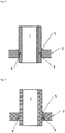
- a starting preform 6 comprising a ductile sheath 7 may consist of a tube open at one end and filled with a core powder material 8 constituent of the brazing alloy. Complete encapsulation of the powder is accomplished with a plug 9 comprising an exit stem tube 10 joined with the sheath by means of a weld or a brazed joint to form a vacuum tight seal 11.
- the alloy composition and wall thickness of the sheath component are determined by the composition and the packing density of the core powder component as exemplified below.
- the sheath can be made by any suitable method.
- a wrought cast bar may be prepared by vacuum induction melting of a charge of alloy elements weighed to meet the nominal composition of the sheath.
- a Ni-Pd-Cr melt charge may comprise electrolytic nickel pieces, palladium shots and chromium flake of 99.95% purity or higher. Melting may be performed in a zirconia or alumina crucible, although zirconia is a preferred (but not essential) refractory material for melting chromium containing alloys.
- the sheath inner channel may be formed by gun drilling or alternatively by sink electric discharge machining (EDM); however the first method is preferable for higher recovery of precious metal containing chips.
- EDM sink electric discharge machining
- Fig. 4 shows an apparatus for degassing the core powder component in the sheath. Without degassing, adsorbed gases on powder particles surface may evolve upon processing into blisters that could adversely affect the integrity of the consolidated powder body. Degassing while the powder is in the sheath reduces the risk of re-adsorption of gases onto the powder. Degassing comprises heating the powder while under an appropriate vacuum.
- the starting preform 6 is connected via the exit stem tube 10 to a vacuum apparatus 12.
- the vacuum apparatus 12 may comprise a mechanical pump 13, diffusion pump 14, and with appropriate valves [roughing valve 15, backing valve 16, and high vacuum valve 17] to permit control of the vacuum. Both a mechanical pump and diffusion pump are shown, but for some materials a mechanical pump alone may provide sufficient vacuum.
- the preform 6 is housed in a heater 19, which may be of any type appropriate to provide the desired degassing temperature.
- the application of heat to the capsule is aimed at accelerating the degassing operation and forcing desorption of gas species.
- heating to 300-600°C range is desirable to thermally activate the desorption process.
- evacuation of the encapsulated powder is carried out until a suitable vacuum is reached [e.g. 1.3Pa (about 0.01 torr) at a leak rate of no more than 13Pa (about 0.1 torr) per minute].
- a suitable vacuum e.g. 1.3Pa (about 0.01 torr) at a leak rate of no more than 13Pa (about 0.1 torr) per minute.
- the degassing process is typically complete and the stem tube may be crimped to keep the encapsulated powder under vacuum. [A like degassing procedure can be applied to manufacture of composite wires as described above].
- Figure 5 shows schematically the steps of a wire forming process that may be used to reduce the sealed preform 6 into a wire of less than 1 mm diameter size.
- First reductions of the preform by 22% of area size are accomplished by swaging 20.
- the radial compression associated with swaging process helps in preventing damage to the vacuum seal 11 and promotes optimal packing and homogeneous distribution of the powder component within the sheath 7. Swaging dies of incrementally decreasing sizes are used for each reduction at a given die size.
- Annealing 21 can be either performed after completion of the forming process step or at any given stage during forming depending on the rate of strain hardening of the sheath material. Excessive strain hardening reduces formability of the material and may cause premature rupture of the sheath 7. Annealing is preferably conducted for sufficient time at a temperature at which full recovery from imparted cold work in the sheath material is achieved.
- roll drawing 22 Further reduction steps may be accomplished by roll drawing 22.
- the wire is drawn between two rolls within a groove of the desired size.
- the forming stress is predominantly compressive with a minor tensile component. This stress condition prevents tearing of wall of the sheath 7 and promotes homogeneous flow of the powder which in turn prevents necking of the wire. This step may account for a 40% area reduction.
- a further area reduction may be carried out on a deep drawing bench 23.
- the deformation mechanism in deep drawing proceeds essentially by axial tension, care needs to be exercised not to stretch the sheath 7 beyond its rupture strength. In general it is recommended to proceed with small deformations and die size reduction increments while performing stress relieving anneals more often. Due to the higher risk of wire rupture encountered in deep drawing, this process is usually performed with sufficient lubrication with commercially available lubricants, for example those consisting of water soluble sodium sulfonates mixed with fatty oils.
- the invention is not limited to the specific steps and specific order shown schematically in Fig. 5 but encompasses any method of reducing a preform down to the brazing alloy wire of the present invention. Like steps may be performed on homogeneous composite wires as on cored wires.
- Example 3 Ni57.1-Pd30.0-Cr10.5-B2.4
- wt.% can be produced as a 1mm (0.04") or less cored wire by the above described methods.
- the powder component used would be CrB 2 , chromium diboride, which is readily available and can be found in purities of 99.9% or higher.
- the particles of commercially available CrB 2 tend to be rough and jagged in form, resulting in particle agglomeration during the drawing process leading to rupture of the sheath.
- the CrB 2 may be spheroidized, for example spheroidized by plasma spraying either as particles or agglomerates of particles, to form more rounded particles.
- the particles should be selected to have a size distribution in which 25% by weight or less comprise particles less than 25 ⁇ m in size. Preferably less than 5% by weight comprises particles less than 20 ⁇ m in size.
- Spheroidization by plasma spraying is a process in which the particles are injected into a plasma and undergo in-flight heating and melting [in whole or in part] followed by cooling and solidification.
- the particles produced by this process tend to be spherical or rounded in form.
- An appropriate alloy composition for the sheath was calculated as Ni62.18-Pd32.67-Cr5.15 wt.%.
- a measured packing density for CrB 2 powder was 2.76 g/cm 3 , which yielded a wall thickness of 7.34mm (0.289") for a sheath external diameter of 28.58mm (1.125").
- Fig. 6 shows a section of a cylindrical tubular preform comprising a sheath having an inside radius r ins and outside radius r out .
- an alloy comprising (Ni50.0-Pd36.0-Cr10.5-B3.0-Si0.5) wt.% may be produced as a 1mm (0.04") or less cored wire by the above described methods.
- the powder component used in this example would be a blend of 91.4wt% CrB 2 chromium diboride and 8.6wt% CrSi 2 chromium disilicide, both readily available and which can be found in purities of 99.9% or higher.
- the particles of the powder should be selected to have a size distribution in which 25% by weight or less comprise particles less than 25 ⁇ m in size, preferably comprising less than 5% by weight of particles less than 20 ⁇ m in size, and may be spheroidized if too jagged in form.
- the calculated alloy composition for the sheath was determined to be Ni56.29-Pd40.53-Cr3.18 wt.%.
- the measured packing density for CrB 2 and CrSi 2 powder blend was 2.75 g/cm 3 , which yields a wall thickness of 6.32mm (0.249") at for a sheath external diameter of 28.58mm (1.125").
- the powder component used in this example is a gas atomized Ni46.26-Cr40.30-B11.52-Si1.92 wt. % powder prepared with electrolytic nickel pieces, and chromium flake of 99.95% purity or higher.
- Boron melt stock is supplied in pellets 95% pure in which most impurities are volatile elements that were readily eliminated during vacuum induction melting prior to atomization.
- Silicon was supplied in high purity lump form.
- the resulting purity of the gas atomized powder was about 99.97%.
- the powder produced was a -100 mesh powder [90% by weight having a particle size less than 149 ⁇ m] which was highly spherical with a small fraction of fine particles (particles less than 25 ⁇ m constituting less than 25% by weight). It has a liquidus temperature of about 1788oC (3250oF).
- the calculated alloy composition for the sheath was determined to be Ni51.32-Pd48.68 wt.%.
- Measured packing density for the gas atomized Ni46.26-Cr40.30-B11.52-Si1.92 wt. % powder was 6.21 g/cm 3 , which yields a wall thickness of 4.13mm (0.1625") at for a sheath external diameter of 28.58mm (1.125").
- Ni-Pd-(Cr) sheath compositions of Examples 4 and 5 Based on the stress relief temperature that was found to be effective for softening the Ni-Pd-(Cr) sheath compositions of Examples 4 and 5, all Ni-Cr-B powder compositions having a liquidus temperature equal to or higher than about 1593oC (2900oF) should not sinter.
- These compositions include, for example:
- An alloy of the same composition as Examples 5 and 6 was produced as a 0.762mm (0.030") cored wire by the above described methods using a 28.58mm (1.125”) outer diameter sheath having a 4.06mm (0.16") thick wall comprising 51.5wt% Pd and 48.5% nickel filled with 100 mesh gas atomized powder of composition in wt% Ni 46.2%,Cr 40.4%, B 11.5%, Si 1.9%.
- cored wire alloy designs are possible and not limited to the examples listed in this disclosure.
- one preferred alternative would be to use a nickel bar of the required purity (99.9% or higher) and formulate a single pre-alloyed powder or a blend of alloy powders of suitable composition to obtain the desired alloy for the cored wire. This approach minimizes the amount of loss of other elements in the drilling process, which is particularly important when the overall alloy composition comprises precious metals.
- a 6.35mm (0.25”) outer diameter 0.89mm(0.035") thick wall nickel tube filled with a Ni-Cr-B-Si high melting temperature alloy gas atomized powder was drawn through a single swagger pass and a sequence of deep drawing steps with alternating anneals at 1350 °C down to 0.76mm (0.030") wire diameter size.
- This can enable the manufacture of brittle alloys wires such as:
- the present invention requires that the particles have a size distribution in which 25% by weight or less comprise particles less than 25 ⁇ m in size, preferably comprising less than 5% by weight of particles less than 20 ⁇ m in size. It is of course required that the particles are not so large as to disrupt the formation of the wire. Accordingly it is required that the core powder does not comprise particles greater than 75% the diameter of the wire, preferably less than 50% the diameter of the wire.
- an upper bound for the particles is 300 ⁇ m [e.g. -50 mesh (about 297 ⁇ m)] with smaller upper limits [e.g ⁇ 250 ⁇ m, ⁇ 200 ⁇ m, ⁇ 150 ⁇ m] being preferred.
- the wires can be bent to shape [e.g. rings] using conventional methods and if necessary annealed before use.
- resilient wires and shapes can be formed of brazing alloys that conventionally would lack required resilience.
- the person skilled in the art will readily see variants of the invention described, and all such variants are intended to be covered by the invention.
Landscapes
- Engineering & Computer Science (AREA)
- Mechanical Engineering (AREA)
- Chemical & Material Sciences (AREA)
- Materials Engineering (AREA)
- Metallurgy (AREA)
- Organic Chemistry (AREA)
- Crystallography & Structural Chemistry (AREA)
- Manufacturing & Machinery (AREA)
- Physics & Mathematics (AREA)
- Thermal Sciences (AREA)
- Composite Materials (AREA)
- Powder Metallurgy (AREA)
Claims (18)
- Fil d'alliage de brasage formé d'un composite comprenant une gaine d'au moins une première phase ductile et un coeur comprenant des particules d'une composition différente de la gaine, dans lesquels:• la gaine a une température de recuit en degrés K• les particules ont un point de fusion au moins 20% supérieur à la température de recuit de la gaine• les particules ont une distribution de taille dans laquelle 25% en poids ou moins comprennent des particules de moins de 25 µm• les particules sont discrètes• les particules ont une teneur en métal libre inférieure à 10% en volume• les particules ont une convexité supérieure à 0,7• les particules ont un ratio d'aspect inférieur à 4:1la composition globale du composite étant équivalente à une composition d'alliage à faible ductilité.
- Fil d'alliage de brasage selon la revendication 1, dans lequel les particules ont un rapport d'aspect inférieur à 2:1 ou inférieur à 3:2.
- Fil d'alliage de brasage selon l'une quelconque des revendications 1 à 2, dans lequel les particules ont un point de fusion au moins 30% supérieur à la température de recuit de la gaine, ou au moins 40% supérieure à la température de recuit de la gaine.
- Fil d'alliage de brasage selon l'une quelconque des revendications 1 à 3, dans lequel les particules sont des particules à faible ductilité.
- Fil d'alliage selon la revendication 1, dans lequel les particules ont une convexité supérieure à 0,8 ou supérieure à 0,9.
- Fil d'alliage de brasage selon l'une quelconque des revendications 1 à 5, dans lequel la composition à faible ductilité est un alliage choisi dans le groupe comprenant les alliages à base d'aluminium, les alliages à base de magnésium, les alliages à base de cuivre, les alliages à base d'or, le palladium. alliages à base, alliages à base de nickel et alliages à base de cobalt.
- Fil d'alliage de brasage selon l'une quelconque des revendications 1 à 6, dans lequel le fil d'alliage de brasage est un fil recuit.
- Fil d'alliage de brasage selon l'une quelconque des revendications 1 à 7, dans lequel le fil se présente sous la forme d'un anneau.
- Fil d'alliage de brasage selon l'une quelconque des revendications 1 à 8, dans lequel le fil a un diamètre inférieur à 1 mm ou inférieur à 0,5 mm ou inférieur à 0,25 mm.
- Procédé pour former un fil en alliage de brasage selon l'une quelconque des revendications 1 à 9, comprenant:a) fournir une préforme en composite comprenant une gaine de la ou des premières phases ductiles et une âme comprenant des particules d'une composition différente de la gaine dans laquelle:• la gaine a une température de recuit en degrés K• les particules ont un point de fusion au moins 20% supérieur à la température de recuit de la gaine• les particules ont une distribution de taille dans laquelle 25% en poids ou moins comprennent des particules de moins de 25 µm• les particules sont discrètes• les particules ont une teneur en métal libre inférieure à 10% en volume• les particules ont une convexité supérieure à 0,7• les particules ont un ratio d'aspect inférieur à 4: 1la composition globale du composite étant équivalente à une composition d'alliage à faible ductilité;
etb) en deux ou plusieurs étapes de réduction, en réduisant le diamètre de la préforme tout en augmentant la longueur de la préforme pour former le fil;
et
dans lequel une ou plusieurs étapes de recuit sont prévues entre les deux étapes de réduction ou plus pour restaurer la ductilité à la gaine. - Procédé selon la revendication 10, dans lequel les deux étapes de réduction ou plus comprennent une ou plusieurs étapes de matriçage.
- Procédé selon la revendication 10 ou 11, dans lequel les deux étapes de réduction ou plus comprennent une ou plusieurs étapes d'étirage.
- Procédé selon l'une quelconque des revendications 10 à 12, dans lequel les deux étapes de réduction ou plus comprennent une ou plusieurs étapes d'emboutissage profondes.
- Procédé selon l'une quelconque des revendications 10 à 13, dans lequel les deux étapes de réduction ou plus comprennent une combinaison de deux étapes de réduction différentes ou plus choisies parmi le groupage, le dessin au rouleau et l'emboutissage.
- Procédé selon l'une quelconque des revendications 10 à 14, dans lequel le matériau de la préforme est dégazé avant la ou les étapes de réduction.
- Procédé selon l'une quelconque des revendications 10 à 15, dans lequel la ou les premières phases ductiles sont présentes dans des proportions suffisantes pour permettre l'étirage du composite jusqu'à une réduction de diamètre de 5% ou plus.
- Procédé de brasage au four comprenant l'utilisation d'un fil d'alliage de brasage selon l'une quelconque des revendications 1 à 9 pour joindre des pièces pour former un article.
- Article comprenant un joint brasé produit par le procédé de la revendication 17.
Applications Claiming Priority (2)
| Application Number | Priority Date | Filing Date | Title |
|---|---|---|---|
| US201461942208P | 2014-02-20 | 2014-02-20 | |
| PCT/EP2015/053486 WO2015124665A1 (fr) | 2014-02-20 | 2015-02-19 | Fils en alliage de brasage et de soudage |
Publications (2)
| Publication Number | Publication Date |
|---|---|
| EP3107684A1 EP3107684A1 (fr) | 2016-12-28 |
| EP3107684B1 true EP3107684B1 (fr) | 2018-09-26 |
Family
ID=52477809
Family Applications (1)
| Application Number | Title | Priority Date | Filing Date |
|---|---|---|---|
| EP15705027.9A Active EP3107684B1 (fr) | 2014-02-20 | 2015-02-19 | Fils en alliage de brasage et methode de brassage |
Country Status (6)
| Country | Link |
|---|---|
| US (1) | US10124443B2 (fr) |
| EP (1) | EP3107684B1 (fr) |
| JP (1) | JP2017511753A (fr) |
| CA (1) | CA2939189C (fr) |
| SG (1) | SG11201606845TA (fr) |
| WO (1) | WO2015124665A1 (fr) |
Families Citing this family (1)
| Publication number | Priority date | Publication date | Assignee | Title |
|---|---|---|---|---|
| DE102015105069B4 (de) * | 2015-04-01 | 2022-04-28 | Karl Storz Se & Co. Kg | Verfahren zum Verbinden mindestens zweier Bauteile eines Endoskops |
Family Cites Families (19)
| Publication number | Priority date | Publication date | Assignee | Title |
|---|---|---|---|---|
| US2888740A (en) | 1952-07-15 | 1959-06-02 | Eaton Mfg Co | Composite ductile wire |
| US2862844A (en) * | 1954-12-09 | 1958-12-02 | Daystrom Inc | Composite brazing material |
| GB1383304A (en) | 1971-02-09 | 1974-02-12 | British Oxygen Co Ltd | Welding consumables |
| US3986899A (en) * | 1974-06-07 | 1976-10-19 | Scm Corporation | Atomized copper brazing paste |
| JPS56126093A (en) * | 1980-03-07 | 1981-10-02 | Sumitomo Metal Ind Ltd | Soldering material |
| GB8409047D0 (en) * | 1984-04-07 | 1984-05-16 | Mixalloy Ltd | Production of metal strip |
| US4800131A (en) | 1984-12-20 | 1989-01-24 | Alloy Rods Global, Inc. | Cored wire filler metals and a method for their manufacture |
| JPS6281287A (ja) * | 1985-10-03 | 1987-04-14 | Daido Steel Co Ltd | 溶接用複合ワイヤ |
| US4897243A (en) | 1988-11-07 | 1990-01-30 | Gte Products Corporation | Ductile brazing alloy of copper-nickel-silicon-titanium |
| US5368220A (en) | 1992-08-04 | 1994-11-29 | Morgan Crucible Company Plc | Sealed conductive active alloy feedthroughs |
| JPH06226486A (ja) | 1993-01-29 | 1994-08-16 | Nippon Steel Weld Prod & Eng Co Ltd | Migろう付け用複合ワイヤ |
| US5781846A (en) * | 1993-02-25 | 1998-07-14 | Jossick; James L. | Flux cored brazing composition |
| JPH06269985A (ja) | 1993-03-19 | 1994-09-27 | Nippon Steel Weld Prod & Eng Co Ltd | Migろう付け用複合ワイヤ |
| JP2005081382A (ja) * | 2003-09-09 | 2005-03-31 | Oki Electric Ind Co Ltd | ソルダペースト |
| JP2005205466A (ja) * | 2004-01-23 | 2005-08-04 | Nippon Light Metal Co Ltd | アルミニウム合金ろう付け用ろう材ワイヤ |
| EP1930115A1 (fr) * | 2006-11-20 | 2008-06-11 | Siemens Aktiengesellschaft | Fil, son utilisation et procédé de soudage |
| EP2104581A2 (fr) * | 2006-12-21 | 2009-09-30 | Arcmelt Company, Lc. | Produit de type fil à âme composite et procédé de fabrication associé |
| FR2989921B1 (fr) | 2012-04-27 | 2015-05-15 | Hexcel Reinforcements | Utilisation, dans la fabrication d'une piece composite, d'une operation de penetration, pour ameliorer la conductivite electrique transverse de la piece composite |
| DE102012017677A1 (de) | 2012-09-07 | 2014-03-13 | Kiekert Aktiengesellschaft | Kraftfahrzeugtürschloss |
-
2015
- 2015-02-19 WO PCT/EP2015/053486 patent/WO2015124665A1/fr active Application Filing
- 2015-02-19 SG SG11201606845TA patent/SG11201606845TA/en unknown
- 2015-02-19 CA CA2939189A patent/CA2939189C/fr active Active
- 2015-02-19 EP EP15705027.9A patent/EP3107684B1/fr active Active
- 2015-02-19 US US15/119,171 patent/US10124443B2/en active Active
- 2015-02-19 JP JP2016552592A patent/JP2017511753A/ja active Pending
Non-Patent Citations (1)
| Title |
|---|
| None * |
Also Published As
| Publication number | Publication date |
|---|---|
| WO2015124665A1 (fr) | 2015-08-27 |
| CA2939189C (fr) | 2023-10-03 |
| SG11201606845TA (en) | 2016-09-29 |
| JP2017511753A (ja) | 2017-04-27 |
| US10124443B2 (en) | 2018-11-13 |
| EP3107684A1 (fr) | 2016-12-28 |
| CA2939189A1 (fr) | 2015-08-27 |
| US20170008130A1 (en) | 2017-01-12 |
Similar Documents
| Publication | Publication Date | Title |
|---|---|---|
| Wu | Fabrication of nitinol materials and components | |
| US4710235A (en) | Process for preparation of liquid phase bonded amorphous materials | |
| CN103443311B (zh) | 用于生产钛合金焊丝的方法 | |
| EP2832488A1 (fr) | Alliages de brassage | |
| JP6860484B2 (ja) | ろう付け合金 | |
| EP2491155B1 (fr) | Process de fabrication de fil de soudage de titane | |
| CN101623800B (zh) | 镁基钎料合金及其制备方法 | |
| CN109465563B (zh) | 一种Al-Cu-Si-Ni-Mg-Ti-Bi铝基合金态钎料及其制备方法 | |
| US20120148440A1 (en) | Copper brazing filler metal | |
| JP5726457B2 (ja) | チタン製品またはチタン合金製品の製造方法 | |
| WO2017018514A1 (fr) | Matériau composite de titane, et matériau de titane pour laminage à chaud | |
| EP3137253B1 (fr) | Matériau de soudure à base de nickel comportant du bore ductile | |
| JP5548578B2 (ja) | 高強度マグネシウム合金線材及びその製造方法、高強度マグネシウム合金部品、並びに高強度マグネシウム合金ばね | |
| EP2840155B1 (fr) | Élément en alliage de magnésium et procédé de fabrication correspondant | |
| EP3107684B1 (fr) | Fils en alliage de brasage et methode de brassage | |
| CN109465569A (zh) | 一种高温钎焊用钛基钎料及制备方法 | |
| JP6128289B1 (ja) | チタン複合材および熱間圧延用チタン材 | |
| JPS63212088A (ja) | 均質低融点銅基合金 | |
| CN103273211B (zh) | 一种镁合金药芯钎焊丝及其制备方法 | |
| CN111151864B (zh) | 连接钨基粉末合金与低膨胀高温合金的焊接材料和工艺 | |
| Cui et al. | Development of low‐melting‐point filler materials for laser beam brazing of aluminum alloys: Entwicklung von Lötdrähten mit niedriger Schmelztemperatur für das Laserstrahllöten von Aluminium | |
| CN107735213A (zh) | 合金 | |
| WO2013119767A1 (fr) | Alliage de brasage et procédés de fabrication et d'utilisation | |
| JPH05320813A (ja) | 強度,耐熱性に優れたモリブデン又はモリブデン合金部材 | |
| Trykov et al. | Using explosion welding for producing multicomponent active brazing alloys |
Legal Events
| Date | Code | Title | Description |
|---|---|---|---|
| PUAI | Public reference made under article 153(3) epc to a published international application that has entered the european phase |
Free format text: ORIGINAL CODE: 0009012 |
|
| STAA | Information on the status of an ep patent application or granted ep patent |
Free format text: STATUS: REQUEST FOR EXAMINATION WAS MADE |
|
| 17P | Request for examination filed |
Effective date: 20160910 |
|
| AK | Designated contracting states |
Kind code of ref document: A1 Designated state(s): AL AT BE BG CH CY CZ DE DK EE ES FI FR GB GR HR HU IE IS IT LI LT LU LV MC MK MT NL NO PL PT RO RS SE SI SK SM TR |
|
| AX | Request for extension of the european patent |
Extension state: BA ME |
|
| RIC1 | Information provided on ipc code assigned before grant |
Ipc: B23K 35/02 20060101ALI20161220BHEP Ipc: C21D 7/10 20060101ALI20161220BHEP Ipc: B22F 1/00 20060101AFI20161220BHEP Ipc: B22F 7/08 20060101ALI20161220BHEP Ipc: B23K 35/40 20060101ALI20161220BHEP Ipc: B23K 35/30 20060101ALI20161220BHEP Ipc: B22F 5/12 20060101ALI20161220BHEP Ipc: B22F 3/17 20060101ALI20161220BHEP |
|
| DAX | Request for extension of the european patent (deleted) | ||
| GRAP | Despatch of communication of intention to grant a patent |
Free format text: ORIGINAL CODE: EPIDOSNIGR1 |
|
| STAA | Information on the status of an ep patent application or granted ep patent |
Free format text: STATUS: GRANT OF PATENT IS INTENDED |
|
| RIC1 | Information provided on ipc code assigned before grant |
Ipc: B23K 35/30 20060101ALI20170522BHEP Ipc: B23K 35/02 20060101ALI20170522BHEP Ipc: C21D 7/10 20060101ALI20170522BHEP Ipc: B22F 5/12 20060101ALI20170522BHEP Ipc: B21C 1/02 20060101AFI20170522BHEP Ipc: B23K 35/40 20060101ALI20170522BHEP Ipc: C22F 1/10 20060101ALI20170522BHEP Ipc: C22C 19/05 20060101ALI20170522BHEP Ipc: C22C 30/00 20060101ALI20170522BHEP Ipc: C22C 5/02 20060101ALI20170522BHEP |
|
| INTG | Intention to grant announced |
Effective date: 20170613 |
|
| GRAJ | Information related to disapproval of communication of intention to grant by the applicant or resumption of examination proceedings by the epo deleted |
Free format text: ORIGINAL CODE: EPIDOSDIGR1 |
|
| STAA | Information on the status of an ep patent application or granted ep patent |
Free format text: STATUS: REQUEST FOR EXAMINATION WAS MADE |
|
| INTC | Intention to grant announced (deleted) | ||
| STAA | Information on the status of an ep patent application or granted ep patent |
Free format text: STATUS: EXAMINATION IS IN PROGRESS |
|
| 17Q | First examination report despatched |
Effective date: 20171220 |
|
| REG | Reference to a national code |
Ref country code: DE Ref legal event code: R079 Ref document number: 602015016926 Country of ref document: DE Free format text: PREVIOUS MAIN CLASS: B23K0035300000 Ipc: B22F0001000000 |
|
| RIC1 | Information provided on ipc code assigned before grant |
Ipc: B22F 3/17 20060101ALI20180322BHEP Ipc: C21D 7/10 20060101ALI20180322BHEP Ipc: B21C 1/02 20060101ALI20180322BHEP Ipc: C22C 19/05 20060101ALI20180322BHEP Ipc: B22F 1/00 20060101AFI20180322BHEP Ipc: C22F 1/14 20060101ALI20180322BHEP Ipc: B22F 7/08 20060101ALI20180322BHEP Ipc: B23K 35/40 20060101ALI20180322BHEP Ipc: B22F 5/12 20060101ALI20180322BHEP Ipc: B23K 35/30 20060101ALI20180322BHEP Ipc: B23K 35/02 20060101ALI20180322BHEP Ipc: C22C 5/02 20060101ALI20180322BHEP |
|
| GRAP | Despatch of communication of intention to grant a patent |
Free format text: ORIGINAL CODE: EPIDOSNIGR1 |
|
| STAA | Information on the status of an ep patent application or granted ep patent |
Free format text: STATUS: GRANT OF PATENT IS INTENDED |
|
| INTG | Intention to grant announced |
Effective date: 20180507 |
|
| GRAS | Grant fee paid |
Free format text: ORIGINAL CODE: EPIDOSNIGR3 |
|
| GRAA | (expected) grant |
Free format text: ORIGINAL CODE: 0009210 |
|
| STAA | Information on the status of an ep patent application or granted ep patent |
Free format text: STATUS: THE PATENT HAS BEEN GRANTED |
|
| AK | Designated contracting states |
Kind code of ref document: B1 Designated state(s): AL AT BE BG CH CY CZ DE DK EE ES FI FR GB GR HR HU IE IS IT LI LT LU LV MC MK MT NL NO PL PT RO RS SE SI SK SM TR |
|
| REG | Reference to a national code |
Ref country code: GB Ref legal event code: FG4D |
|
| REG | Reference to a national code |
Ref country code: CH Ref legal event code: EP |
|
| REG | Reference to a national code |
Ref country code: AT Ref legal event code: REF Ref document number: 1045396 Country of ref document: AT Kind code of ref document: T Effective date: 20181015 |
|
| REG | Reference to a national code |
Ref country code: IE Ref legal event code: FG4D |
|
| REG | Reference to a national code |
Ref country code: DE Ref legal event code: R096 Ref document number: 602015016926 Country of ref document: DE |
|
| REG | Reference to a national code |
Ref country code: NL Ref legal event code: MP Effective date: 20180926 |
|
| PG25 | Lapsed in a contracting state [announced via postgrant information from national office to epo] |
Ref country code: NO Free format text: LAPSE BECAUSE OF FAILURE TO SUBMIT A TRANSLATION OF THE DESCRIPTION OR TO PAY THE FEE WITHIN THE PRESCRIBED TIME-LIMIT Effective date: 20181226 Ref country code: GR Free format text: LAPSE BECAUSE OF FAILURE TO SUBMIT A TRANSLATION OF THE DESCRIPTION OR TO PAY THE FEE WITHIN THE PRESCRIBED TIME-LIMIT Effective date: 20181227 Ref country code: FI Free format text: LAPSE BECAUSE OF FAILURE TO SUBMIT A TRANSLATION OF THE DESCRIPTION OR TO PAY THE FEE WITHIN THE PRESCRIBED TIME-LIMIT Effective date: 20180926 Ref country code: RS Free format text: LAPSE BECAUSE OF FAILURE TO SUBMIT A TRANSLATION OF THE DESCRIPTION OR TO PAY THE FEE WITHIN THE PRESCRIBED TIME-LIMIT Effective date: 20180926 Ref country code: SE Free format text: LAPSE BECAUSE OF FAILURE TO SUBMIT A TRANSLATION OF THE DESCRIPTION OR TO PAY THE FEE WITHIN THE PRESCRIBED TIME-LIMIT Effective date: 20180926 Ref country code: BG Free format text: LAPSE BECAUSE OF FAILURE TO SUBMIT A TRANSLATION OF THE DESCRIPTION OR TO PAY THE FEE WITHIN THE PRESCRIBED TIME-LIMIT Effective date: 20181226 Ref country code: LT Free format text: LAPSE BECAUSE OF FAILURE TO SUBMIT A TRANSLATION OF THE DESCRIPTION OR TO PAY THE FEE WITHIN THE PRESCRIBED TIME-LIMIT Effective date: 20180926 |
|
| REG | Reference to a national code |
Ref country code: LT Ref legal event code: MG4D |
|
| PG25 | Lapsed in a contracting state [announced via postgrant information from national office to epo] |
Ref country code: AL Free format text: LAPSE BECAUSE OF FAILURE TO SUBMIT A TRANSLATION OF THE DESCRIPTION OR TO PAY THE FEE WITHIN THE PRESCRIBED TIME-LIMIT Effective date: 20180926 Ref country code: LV Free format text: LAPSE BECAUSE OF FAILURE TO SUBMIT A TRANSLATION OF THE DESCRIPTION OR TO PAY THE FEE WITHIN THE PRESCRIBED TIME-LIMIT Effective date: 20180926 Ref country code: HR Free format text: LAPSE BECAUSE OF FAILURE TO SUBMIT A TRANSLATION OF THE DESCRIPTION OR TO PAY THE FEE WITHIN THE PRESCRIBED TIME-LIMIT Effective date: 20180926 |
|
| REG | Reference to a national code |
Ref country code: AT Ref legal event code: MK05 Ref document number: 1045396 Country of ref document: AT Kind code of ref document: T Effective date: 20180926 |
|
| PG25 | Lapsed in a contracting state [announced via postgrant information from national office to epo] |
Ref country code: NL Free format text: LAPSE BECAUSE OF FAILURE TO SUBMIT A TRANSLATION OF THE DESCRIPTION OR TO PAY THE FEE WITHIN THE PRESCRIBED TIME-LIMIT Effective date: 20180926 Ref country code: AT Free format text: LAPSE BECAUSE OF FAILURE TO SUBMIT A TRANSLATION OF THE DESCRIPTION OR TO PAY THE FEE WITHIN THE PRESCRIBED TIME-LIMIT Effective date: 20180926 Ref country code: IS Free format text: LAPSE BECAUSE OF FAILURE TO SUBMIT A TRANSLATION OF THE DESCRIPTION OR TO PAY THE FEE WITHIN THE PRESCRIBED TIME-LIMIT Effective date: 20190126 Ref country code: PL Free format text: LAPSE BECAUSE OF FAILURE TO SUBMIT A TRANSLATION OF THE DESCRIPTION OR TO PAY THE FEE WITHIN THE PRESCRIBED TIME-LIMIT Effective date: 20180926 Ref country code: ES Free format text: LAPSE BECAUSE OF FAILURE TO SUBMIT A TRANSLATION OF THE DESCRIPTION OR TO PAY THE FEE WITHIN THE PRESCRIBED TIME-LIMIT Effective date: 20180926 Ref country code: IT Free format text: LAPSE BECAUSE OF FAILURE TO SUBMIT A TRANSLATION OF THE DESCRIPTION OR TO PAY THE FEE WITHIN THE PRESCRIBED TIME-LIMIT Effective date: 20180926 Ref country code: RO Free format text: LAPSE BECAUSE OF FAILURE TO SUBMIT A TRANSLATION OF THE DESCRIPTION OR TO PAY THE FEE WITHIN THE PRESCRIBED TIME-LIMIT Effective date: 20180926 Ref country code: CZ Free format text: LAPSE BECAUSE OF FAILURE TO SUBMIT A TRANSLATION OF THE DESCRIPTION OR TO PAY THE FEE WITHIN THE PRESCRIBED TIME-LIMIT Effective date: 20180926 Ref country code: EE Free format text: LAPSE BECAUSE OF FAILURE TO SUBMIT A TRANSLATION OF THE DESCRIPTION OR TO PAY THE FEE WITHIN THE PRESCRIBED TIME-LIMIT Effective date: 20180926 |
|
| PG25 | Lapsed in a contracting state [announced via postgrant information from national office to epo] |
Ref country code: PT Free format text: LAPSE BECAUSE OF FAILURE TO SUBMIT A TRANSLATION OF THE DESCRIPTION OR TO PAY THE FEE WITHIN THE PRESCRIBED TIME-LIMIT Effective date: 20190126 Ref country code: SM Free format text: LAPSE BECAUSE OF FAILURE TO SUBMIT A TRANSLATION OF THE DESCRIPTION OR TO PAY THE FEE WITHIN THE PRESCRIBED TIME-LIMIT Effective date: 20180926 Ref country code: SK Free format text: LAPSE BECAUSE OF FAILURE TO SUBMIT A TRANSLATION OF THE DESCRIPTION OR TO PAY THE FEE WITHIN THE PRESCRIBED TIME-LIMIT Effective date: 20180926 |
|
| REG | Reference to a national code |
Ref country code: DE Ref legal event code: R097 Ref document number: 602015016926 Country of ref document: DE |
|
| PG25 | Lapsed in a contracting state [announced via postgrant information from national office to epo] |
Ref country code: DK Free format text: LAPSE BECAUSE OF FAILURE TO SUBMIT A TRANSLATION OF THE DESCRIPTION OR TO PAY THE FEE WITHIN THE PRESCRIBED TIME-LIMIT Effective date: 20180926 |
|
| PLBE | No opposition filed within time limit |
Free format text: ORIGINAL CODE: 0009261 |
|
| STAA | Information on the status of an ep patent application or granted ep patent |
Free format text: STATUS: NO OPPOSITION FILED WITHIN TIME LIMIT |
|
| 26N | No opposition filed |
Effective date: 20190627 |
|
| REG | Reference to a national code |
Ref country code: CH Ref legal event code: PL |
|
| PG25 | Lapsed in a contracting state [announced via postgrant information from national office to epo] |
Ref country code: SI Free format text: LAPSE BECAUSE OF FAILURE TO SUBMIT A TRANSLATION OF THE DESCRIPTION OR TO PAY THE FEE WITHIN THE PRESCRIBED TIME-LIMIT Effective date: 20180926 Ref country code: MC Free format text: LAPSE BECAUSE OF FAILURE TO SUBMIT A TRANSLATION OF THE DESCRIPTION OR TO PAY THE FEE WITHIN THE PRESCRIBED TIME-LIMIT Effective date: 20180926 Ref country code: LU Free format text: LAPSE BECAUSE OF NON-PAYMENT OF DUE FEES Effective date: 20190219 |
|
| REG | Reference to a national code |
Ref country code: BE Ref legal event code: MM Effective date: 20190228 |
|
| REG | Reference to a national code |
Ref country code: IE Ref legal event code: MM4A |
|
| PG25 | Lapsed in a contracting state [announced via postgrant information from national office to epo] |
Ref country code: CH Free format text: LAPSE BECAUSE OF NON-PAYMENT OF DUE FEES Effective date: 20190228 Ref country code: LI Free format text: LAPSE BECAUSE OF NON-PAYMENT OF DUE FEES Effective date: 20190228 |
|
| PG25 | Lapsed in a contracting state [announced via postgrant information from national office to epo] |
Ref country code: IE Free format text: LAPSE BECAUSE OF NON-PAYMENT OF DUE FEES Effective date: 20190219 |
|
| PG25 | Lapsed in a contracting state [announced via postgrant information from national office to epo] |
Ref country code: BE Free format text: LAPSE BECAUSE OF NON-PAYMENT OF DUE FEES Effective date: 20190228 |
|
| PG25 | Lapsed in a contracting state [announced via postgrant information from national office to epo] |
Ref country code: TR Free format text: LAPSE BECAUSE OF FAILURE TO SUBMIT A TRANSLATION OF THE DESCRIPTION OR TO PAY THE FEE WITHIN THE PRESCRIBED TIME-LIMIT Effective date: 20180926 |
|
| PG25 | Lapsed in a contracting state [announced via postgrant information from national office to epo] |
Ref country code: MT Free format text: LAPSE BECAUSE OF NON-PAYMENT OF DUE FEES Effective date: 20190219 |
|
| PG25 | Lapsed in a contracting state [announced via postgrant information from national office to epo] |
Ref country code: CY Free format text: LAPSE BECAUSE OF FAILURE TO SUBMIT A TRANSLATION OF THE DESCRIPTION OR TO PAY THE FEE WITHIN THE PRESCRIBED TIME-LIMIT Effective date: 20180926 |
|
| PG25 | Lapsed in a contracting state [announced via postgrant information from national office to epo] |
Ref country code: HU Free format text: LAPSE BECAUSE OF FAILURE TO SUBMIT A TRANSLATION OF THE DESCRIPTION OR TO PAY THE FEE WITHIN THE PRESCRIBED TIME-LIMIT; INVALID AB INITIO Effective date: 20150219 |
|
| PG25 | Lapsed in a contracting state [announced via postgrant information from national office to epo] |
Ref country code: MK Free format text: LAPSE BECAUSE OF FAILURE TO SUBMIT A TRANSLATION OF THE DESCRIPTION OR TO PAY THE FEE WITHIN THE PRESCRIBED TIME-LIMIT Effective date: 20180926 |
|
| PGFP | Annual fee paid to national office [announced via postgrant information from national office to epo] |
Ref country code: FR Payment date: 20221208 Year of fee payment: 9 |
|
| PGFP | Annual fee paid to national office [announced via postgrant information from national office to epo] |
Ref country code: DE Payment date: 20240219 Year of fee payment: 10 Ref country code: GB Payment date: 20240219 Year of fee payment: 10 |