EP3107671B1 - Pfannenschutzrohr zum giessen von metall, bausatz für kupplungsanordnung zum befestigen des pfannenschutzrohrs an einer pfanne, metallgiesseinrichtung und kupplungsverfahren - Google Patents
Pfannenschutzrohr zum giessen von metall, bausatz für kupplungsanordnung zum befestigen des pfannenschutzrohrs an einer pfanne, metallgiesseinrichtung und kupplungsverfahren Download PDFInfo
- Publication number
- EP3107671B1 EP3107671B1 EP15705020.4A EP15705020A EP3107671B1 EP 3107671 B1 EP3107671 B1 EP 3107671B1 EP 15705020 A EP15705020 A EP 15705020A EP 3107671 B1 EP3107671 B1 EP 3107671B1
- Authority
- EP
- European Patent Office
- Prior art keywords
- ladle
- upstream
- ladle shroud
- latches
- shroud
- Prior art date
- Legal status (The legal status is an assumption and is not a legal conclusion. Google has not performed a legal analysis and makes no representation as to the accuracy of the status listed.)
- Active
Links
Images






Classifications
-
- B—PERFORMING OPERATIONS; TRANSPORTING
- B22—CASTING; POWDER METALLURGY
- B22D—CASTING OF METALS; CASTING OF OTHER SUBSTANCES BY THE SAME PROCESSES OR DEVICES
- B22D41/00—Casting melt-holding vessels, e.g. ladles, tundishes, cups or the like
- B22D41/50—Pouring-nozzles
- B22D41/56—Means for supporting, manipulating or changing a pouring-nozzle
-
- B—PERFORMING OPERATIONS; TRANSPORTING
- B22—CASTING; POWDER METALLURGY
- B22D—CASTING OF METALS; CASTING OF OTHER SUBSTANCES BY THE SAME PROCESSES OR DEVICES
- B22D41/00—Casting melt-holding vessels, e.g. ladles, tundishes, cups or the like
- B22D41/14—Closures
- B22D41/22—Closures sliding-gate type, i.e. having a fixed plate and a movable plate in sliding contact with each other for selective registry of their openings
- B22D41/28—Plates therefor
- B22D41/34—Supporting, fixing or centering means therefor
Definitions
- the present invention relates to nozzles for coupling to a ladle in a metal casting installation (in particular to a steel casting installation), referred to as ladle shrouds.
- ladle shrouds which can be loaded to and unloaded from the bottom base of a ladle, slipped into casting position and which can maintain their casting position without any external means such as a manipulator or a robot.
- the present invention also concerns a kit of part for a coupling assembly allowing such reversible coupling, a metal casting installation comprising such nozzle, and a process of coupling a ladle shroud to the bottom base of a ladle.
- molten metal is transferred from one metallurgical vessel to another, to a mould or to a tool.
- a ladle (11) is filled with molten metal out of a furnace and transferred over a tundish (10) to cast the molten metal through a ladle shroud (111) into said tundish.
- the molten metal can then be cast through a pouring nozzle (101) from the tundish to a mould for forming slabs, billets, beams or ingots.
- Flow of molten metal out of a metallurgic vessel is driven by gravity through a nozzle system (101, 111) located at the bottom of said vessel.
- the inner surface of the bottom floor of a ladle (11) is provided with an inner nozzle (113) comprising an inner bore.
- the outlet end (113b) of said inner nozzle is coupled to a gate (114u, 114d), generally a sliding gate or a rotary gate, controlling the flow of molten metal out of the ladle.
- a ladle shroud (111) is brought in fluid communication (via its upper end) with the outlet end of the inner nozzle while its lower end is immersed into the tundish, generally below the level of molten metal; to form a continuous molten metal flow path shielded from any contact with oxygen between the inlet end (113a) of the inner nozzle (113) within the ladle down to the outlet of the ladle shroud immersed in the liquid metal contained in the tundish.
- a ladle shroud is simply a nozzle comprising a long tubular portion crowned by an upstream coupling portion with a central bore.
- the ladle shroud is inserted about and sealed to a short collector nozzle (110) coupled to, and jutting out of the outer surface of the ladle bottom floor, and which is separated from the inner nozzle (113) by a gate (114u, 114d).
- a ladle is brought to its casting position over a tundish or a mould from a furnace, a converter or another ladle where it was filled with a batch of molten metal, with the gate (114u, 114d) in a closed configuration.
- the ladle is not coupled to any ladle shroud (111) because the latter is long and it would be dangerous to move a ladle back and forth across a workshop with a long ladle shroud jutting out of its lower base.
- a manipulator or a robot (20) brings a ladle shroud into casting configuration.
- the outlet end of the collector nozzle (110) is snuggly nested in the bore inlet of the ladle shroud to form a sealing joint.
- the manipulator or robot (20) must maintain the ladle shroud (111) in its casting configuration during the whole casting of the molten metal batch contained in the ladle (11).
- the gate is closed and the manipulator or robot takes back the ladle shroud to allow the removal of the empty ladle and replacement by another ladle filled with a new batch of molten metal.
- the manipulator or robot (20) repeats the foregoing operations with the new ladle and the same or a new ladle shroud.
- the manipulator or robot (20) must be operational during the whole duration of the casting of molten metal from the ladle into a tundish, and cannot be used in the meantime for other operations, such as measurements of various process parameters, removal of a clogging in the inner nozzle and the like.
- Emergencies may happen, with the gate not functioning properly, requiring the swift removal of the ladle from its casting position to empty the remaining content of molten metal into an appropriate emergency waste area.
- the collector nozzle of the ladle (110) is nested in the bore of the ladle shroud (111) with the manipulator or robot firmly gripping the latter in its casting configuration (cf. Figure 1(b) )
- the emergency removal of the ladle would drag therewith both ladle shroud and manipulator or robot, causing serious damages to the installation. Indeed, the manipulator or robot cannot be dragged very far, and the ladle may be blocked halfway, casting molten metal in an inappropriate area of the workshop causing serious consequences and danger.
- JPS09-201657 proposes a ladle shroud provided with coupling means including a bayonet requiring the rotation of the nozzle about its longitudinal axis to block it in its casting configuration. Such rotation can become very difficult as soon as the slightest amount of molten metal flows into and jags the bayonet mechanism upon freezing.
- JPS09-108825 proposes a ladle shroud comprising two pins on either side thereof suitable for being held in casting configuration by a moving bracket comprising complementary slots for receiving said pins. This mechanism requires an excellent coordination between the loading of a ladle shroud onto the slots of the brackets, and the tilting of the latter in a clamping configuration.
- a plugging material (300), usually sand, is often used to fill the bore of the inner nozzle from its inlet to the closed gate to prevent any molten metal from flowing therein, such that metal freezing and clogging of the nozzle and gate system are prevented.
- the plugging material flows out followed by the molten metal thus preventing any metal from dwelling and freezing in the inner nozzle (113).
- a solid crust of sintered sand impregnated with frozen metal usually forms at the interface between molten metal and sand. In most cases, the crust is thin enough to break under the own weight of molten metal upon opening the gate. Sometimes, however, it may happen that the crust is hard enough to resist the weight of the molten metal. The crust must then be broken or fused with a tool or torch handled manually or with a robot. Because of the length of a ladle shroud, this operation is very cumbersome if the ladle shroud is already coupled to the collector nozzle of the ladle.
- a ladle shroud in a traditional installation such as illustrated in Figure 1(b) must be de-coupled from the collector nozzle, the crust broken or molten with a torch to initiate the casting of molten metal. Coupling the ladle shroud again to the collector nozzle as metal is flowing through the collector nozzle is dangerous as spilling of molten metal is unavoidable.
- a device for inserting and removing ladle nozzles was proposed in WO2004/052576 .
- said device is, however, cumbersome to operate.
- the device is rather large in size and does not provide the necessary visibility to permit an operator to work with the high precision required for the installation of a ladle shroud.
- the lack of clearance with the tilting bar and ribs of the ladle and also between the bottom of the tube and the tundish is a drawback of said coupling assembly.
- the present invention proposes a solution solving all the issues raised above, such as providing a ladle shroud that can be inserted and removed easily, which holds in place without the need of any exterior manipulator or robot, and which allows the coupling to a ladle of a short collector nozzle upon initiation of the casting followed by the replacement thereof without spilling of molten metal by a long ladle shroud once casting has successfully initiated.
- the present invention concerns a shroud (111) for casting metal from a ladle (i.e. a ladle shroud), said nozzle comprising:
- upstream and downstream are used with reference to the casting direction of the molten metal, i.e., “upstream” starting from the ladle (11) and “downstream” ending in the mould (100).
- the space is defined by an orthogonal vectorial system (X1, X2, X3), wherein X1 is the longitudinal axis or direction, X2 the first transverse axis or direction, and X3 the second transverse axis or direction.
- the longitudinal axis, X1 corresponds in use to a substantially vertical direction parallel to the flow direction of molten metal through the various nozzles.
- the directions, X2 and X3, therefore define a plane normal to the longitudinal direction, X1, and is horizontal.
- a ladle shroud (111) is to be coupled to a ladle (11) once the latter is in casting position above a tundish (10) or any other metallurgical vessel or mould.
- a ladle shroud is a long tube used for transferring molten metal from a ladle (11) to a tundish (10) (or other vessel) sheltered from any contact with air to prevent oxidation.
- it is an object of the present invention to provide a ladle shroud which is easy to couple to the bottom base of a ladle (11) and which can be maintained in its casting position without any external tool such as a robot (20).
- a ladle shroud (111) comprises a bore (115) extending parallel to a first longitudinal axis, X1, from an inlet orifice (115a) to an outlet orifice (115b).
- the inlet portion located at an upstream end of prior art ladle shrouds which are to be mounted over a collector nozzle (110) in a nesting relationship is characterized by a conically tapering bore ending in a circular ridge, designed for snuggly fitting a similarly conically tapering portion of a collector nozzle. Sealing contact is ensured at the level of the matching conically tapered collector nozzle and inlet portion of the ladle shroud bore.
- the sealing contact between a ladle (11) and a ladle shroud (111) according to the present invention is ensured by a planar upstream surface slidingly resting against a planar bottom surface of a bottom gate plate (114d) (see e.g., Figure 10 ).
- the inlet portion of a ladle shroud according to the present invention consists of a plate comprising:
- a ladle shroud Downstream of the downstream surface (4d) of the plate, a ladle shroud according to the present invention comprises a tubular portion similar to prior art ladle shrouds, extending along said first longitudinal axis, X1, from said downstream surface (4d) to a downstream end, opposite the upstream end, and where said outlet orifice (115b) is located.
- the geometry of the tubular portion such as its outer diameter, Dt, and of the bore in said tubular portion does not affect the present invention, and any desired shape of the tubular portion known in the art can be applied to a ladle shroud according to the present invention.
- a ladle shroud (111) according to the present invention is characterized over the ladle shrouds of the prior art by the geometry of the inlet portion thereof.
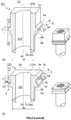
- each of said first and second gripping portions of the peripheral wall comprises an upstream protrusion (3) culminating at an upstream ridge (3r) separating a leading edge (3u) facing towards the upstream end of the ladle shroud from a trailing edge (3d) facing towards the downstream end of the ladle shroud.
- Said upstream protrusion (3) protrudes out beyond the whole peripheral wall of the corresponding gripping portion, said upstream portions (3) extending parallel to the upstream surface (2u) and symmetrically to one another with respect to the longitudinal axis, X1, along the respective first and second gripping portions.
- the leading edge (3u) of the upstream protrusion forms with a plane parallel to the upstream surface an angle, ⁇ 1
- the trailing edge (3d) forms an angle, ⁇ 1, with a plane parallel to the upstream surface (2u), wherein
- the angle, ⁇ 1, of the leading edge (3u) is preferably comprised between 45 and 70°, more preferably between 55 and 65° and the angle, ⁇ 1, of the trailing edge (3d) is preferably smaller than the angle, ⁇ 1, and is more preferably comprised between 25 and 45°, most preferably between 35 and 40°.
- the relevance of the angles, ⁇ 1 and ⁇ 1, of the leading edge and trailing edge of the upstream protrusion (3) will be discussed more in details below together with the drawing frame (210) and support frame (211) used to couple such ladle shroud (111) to a ladle (11).
- the peripheral wall of the ladle shroud (111) comprises a third and a fourth gripping portions separated from each other by the bore (115) and extending symmetrically to each other with respect to the longitudinal axis, X1, from corresponding portions of the upstream perimeter (2p) down to corresponding portions of the downsteam perimeter (4p).
- the third and fourth gripping portions preferably have the same geometry and dimensions as, and extending transverse, generally normal to the first and second gripping portions, and comprise an upstream protrusion (3) of same geometry as the one of the first and second gripping portions.
- the preferred geometry is a square upstream periphery (2p) with curved or preferably straight edges, and with an upstream protrusion (3) as defined above extending along the whole peripheral wall parallel to the upstream surface (2u).
- the upstream surface (2u) must be planar, there is no particular requirement of planarity for any of the remaining surfaces defining the plate of a ladle shroud according to the present invention.
- the portions of the upstream perimeter (2p) and downstream perimeter (4p) corresponding to each of the first and second gripping portions are straight lines.
- the leading edge (3u) and upstream ridge (3r) of the upstream protrusion (3), as well as the downstream surface (4d) be at least partially planar, preferably fully planar.
- the upstream protrusion (3) can be contiguous to the upstream surface (2u), the base of the leading edge (3u) thereof defining a section or the whole of the upstream perimeter (2p) as illustrated in Figure 2(a) .
- the upstream protrusion (3) can be separated from the upstream perimeter (2p) by a portion of the peripheral wall.
- the exact position of the upstream protrusion (3) depends on the geometry of the drawer frame (210) and support frame (211) to which the ladle shroud (111) is to be coupled, and which are discussed more in details below.
- the upstream protrusion (3) normally is the first protrusion encountered when running the peripheral wall of the plate from the upstream surface (2u) down to the downstream surface (4d) thereof.
- the geometry of the upstream protrusion (3) is important as it must be suitable for cooperating with latches mounted on a drawer frame (210) or a support frame (211), to maintain it coupled to the bottom base of a ladle, holding the ladle shroud own weight, while it is not in its casting position.
- the distance, Hu, from the upstream ridge (3r) of the upstream protrusion (3) to the bottom of the leading edge (3u) measured along a plane parallel to the upstream surface is preferably greater than 5 mm, and more preferably comprised between 6 and 15 mm, most preferably between 8 and 12 mm.
- the distance, Hd, from the upstream ridge (3r) of the upstream protrusion (3) to the bottom of the trailing edge (3d) measured along a plane parallel to the upstream surface is, on the other hand, equal or different from Hu, and is preferably greater than 5 mm, more preferably comprised between 6 and 15 mm, most preferably between 8 and 12 mm,
- each of the first and second gripping portions further comprises a downstream protrusion (4) culminating at a downstream ridge (4r) separating a leading edge (4u) facing towards the upstream protrusion (3) from the downstream surface (4d), and extending parallel to the upstream protrusion (3) along the respective first and second gripping portions.
- the upstream ridge (3r) and the downstream ridge (4r) are thus separated from one another by a recess.
- the trailing edge (3d) of the upstream protrusion (3), the leading edge (4u) of the downstream protrusion (4), and the recess separating the upstream from the downstream protrusions define a geometry that matches the profile of the latches (30) used to couple a ladle shroud to a ladle (11).
- the elements required for coupling a ladle shroud (111) according to the present invention to a ladle (11) comprise:
- the gist of the invention is the combination of a pair of resilient latches (30) with the gripping portions of a ladle shroud (111) as discussed supra, wherein the latches (30) are suitable for engaging the gripping portions of the ladle shroud (111).
- the resilient latches (30) must be suitable for:
- the assembly for coupling a ladle shroud (111) to a ladle (11) comprises a drawer frame (210) comprising two longitudinal beams (210x) extending along a first transverse axis, X2, separated from one another by two transverse beams (210y), thus defining a cavity of area and perimeter with a width and length measured along the first and second transverse axes, X2, X3, respectively, which are suitable for snugly accommodating the equivalent of at least one inlet surface (2u) of a ladle shroud (111) as discussed above and illustrated in Figures 4 to 8 .
- the transverse and longitudinal beams are arranged to form an external outline which can be inscribed in a rectangle having a longitudinal length measured along a first transverse axis, X2, and a transverse width measured along a second transverse axis, X3, normal to the first transverse axis, X2, It is preferred that the longitudinal and transverse beams (210x, 210y) be straight and form a rectangle or even a square as shown in Figure 5 .
- the drawer frame (210) must be suitable (a) for hosting at least a ladle shroud (111) and (b) for sliding along a passage (120) of a support frame to bring the bore (115) of a ladle shroud (111) in and out of registry with the opening (114a) of a bottom gate plate (114d), by means of a hydraulic arm (40b) coupled to a transverse beam (210y) of the drawer frame (210) (cf. Figure 3(f) , (g) , (i)&(k) ).
- the bottom floor of a ladle (11) comprises an inner nozzle (113) with a bore extending from an inlet (113a) at an inner end of the inner nozzle to an outlet (113b) at the opposite end of the inner nozzle, said bore bringing in fluid communication the interior of the ladle (11) with the exterior thereof.
- the outlet (113b) of the inner nozzle bore is coupled with a top gate plate (114u) comprising a planar top surface and a planar bottom surface parallel to the planar top surface and separated therefrom by the thickness of the top gate plate, as shown in Figure 10 .
- the top gate plate (114u) is provided with a through-opening extending through the thickness of the top gate plate from the planar top surface to the planar bottom surface, and is stationarily coupled to the outer surface of the bottom floor of a ladle (11) with the through-opening in fluid communication with the outlet orifice (113b) of the inner nozzle (113),
- the assembly for coupling a ladle shroud (111) to a ladle (11) further comprises a support frame (211).
- the support frame comprises a top plate (211u) having a top planar surface normal to a longitudinal axis, X1, normal to both first and second transverse axes, X2, X3, and comprising an opening.
- the top plate (211u) snuggly encases a bottom gate plate (114d) having a planar top surface slightly protruding above the top planar surface (211u) of the support frame (211) and a planar bottom surface, parallel to said top surface and separated therefrom by the thickness of the bottom gate plate.
- the bottom gate plate is provided with an opening (114a) extending through the thickness of the bottom gate plate, parallel to the longitudinal axis, X1.
- the support frame is coupled to the bottom floor of a ladle (11) such that the top surface of the bottom gate plate (114d) is parallel to and in sliding contact with the bottom surface of the top gate plate (114u) and such that it can slid from a sealed position to a casting position and back by means of a hydraulic arm (40a).
- the opening (114a) of the bottom gate (114d) is out of registry with the through-opening of the top gate plate (114u) (cf.
- the support frame (211) For allowing the sliding of the drawer frame (210) holding a ladle shroud (111) to its casting position, the support frame (211) comprises a T-shaped passage (120) extending from a frame inlet along the first transverse axis, X2.
- the vertical bar of the T-passage (120) is suitable for allowing passage of the tubular portion of a ladle shroud (111), whilst the horizontal bar of the T-passage (120) -which extends parallel to the second transverse axis, X3- is suitable for accommodating the drawer frame (210) and sliding it along the passage on two guiding rails (117).
- the two guiding rails (117) extend along the first transverse axis, X2, and parallel to said top planar surface of the top plate (211u), on each protruding end of the horizontal bar of the T-passage, on either side of the vertical bar of the T-passage.
- the guiding rails are separated from one another by a gap having a width measured along the second transverse axis, X3, which is superior to the diameter, Dt, of the tubular portion of the ladle shroud and slightly inferior to the transverse width of the rectangle in which the drawer frame (210) is inscribed.
- the gap In order to allow the insertion from the bottom into the drawer frame (210) of a collector nozzle, the gap should have a width, at least locally greater than the width of the ladle shroud plate and thus of the cavity defined by the drawer frame (210).
- the guiding rails (117) should be suitable for supporting in a sliding relationship the longitudinal beams (210x) of the drawer frame (210), without extending, at least locally over the cavity thereof.
- the support frame (211) must comprise two sets of pushers (118) or rockers positioned adjacent to the two bottom guiding rails (118) on either side of the gap, at the level of the bottom gate plate opening.
- Pushers (118) or rockers are well known in the art with respect to pouring nozzles used in tube exchange devices coupled to the bottom floor of a tundish (10) such as disclosed e.g., in WO2011/113597 .
- Pushers are used for pressing the upstream surface (2u) of a ladle shroud (111) in tight and sealed contact against the lower surface of a bottom gate plate (114d), when the drawing frame (210) and thus the ladle shroud (111) are in their casting position with the ladle shroud bore (115) in registry with the opening (114a) of the bottom gate plate (114d).
- the coupling assembly When the ladle shroud (111) is not in casting position, the coupling assembly must support the ladle shroud own weight only, and the latter can therefore hang on the latches only.
- the drawer frame is slid together with the ladle shroud into their casting position, the ladle shroud rests on the pushers (118) or rockers.
- the pushers ensure, on the one hand, a sealed contact between the ladle shroud and the bottom gate plate and, on the other hand, a strong coupling to the ladle (11) able to resist the pressure of flowing metal through the ladle shroud and, in particular, any hammer possible in particular at the beginning of the casting operation or in case of loosened solid lumps which may have temporarily clogged the bore.
- the resilient latches (30) can be mounted on the drawer frame (210) as illustrated in Figures 3-7 -and 10(a) . Alternatively they can be mounted on the support frame (211) as illustrated in Figures 8 and 10(b) . All that is required is that when the drawer frame (210) is inserted in the passage (120) of the support frame (211), said first and second latches can be located above or below the top sliding surface of the two guiding rails, vis-à-vis one another on either side of the gap formed between the guiding rails.
- the terms "above” and “below” refer herein to the position with respect to the sliding surfaces when the support frame and drawer are coupled to a ladle ready for casting. In case the latches are mounted on the support frame (211) (cf.
- the latches should be offset in the first transverse direction, X2, with respect to the opening (114a) of the bottom gate plate (114d) and thus of the pushers (118) or rockers, to allow enough clearance for the insertion between the two latches of a ladle shroud from the bottom. If the latches (30) are mounted on the drawer frame (210), they will follow the translating movements of the ladle shroud (111) between its hanging and casting positions as the hydraulic arm (40b) moves the drawer frame back and forth. This means that, unlike in the case wherein the latches are mounted on the support frame (211), the ladle shroud (111) remains in contact with the latches also in its casting position.
- each of the two resilient latches (30) comprises a chamfered upstream surface (30u) forming an angle, ⁇ 1, with a plane parallel to the first and second transverse axes, X2-X3, equal to the angle, ⁇ 1, formed by the trailing edge (3d) of the upstream protrusion (3) of a ladle shroud (111) according to the present invention, so that the ladle shroud (111) can rest on a matching surface of the latches.
- Each of the two resilient latches (30) also comprises a chamfered downstream surface (30d) forming an angle, ⁇ 1, with a plane parallel to the first and second transverse axes, X2-X3, equal to the angle, ⁇ 1, formed by the leading edge (3u) of the upstream protrusion (3) of a ladle shroud (111).
- the leading edge (4u) of said downstream protrusion should form the same angle, ⁇ 1, as the downstream surface (30d) of the latches so that the two surfaces are in matching contact as illustrated in Figure 10 .
- the ladle shroud geometry defined by the recess formed between the upstream and downstream protrusions (3, 4) should match the geometry of the latches (30) defined by the upstream and downstream surfaces (30u, 30d) and the surface separating them. This allows a stable and reproducible gripping of a ladle shroud between the latches.
- the latches (30) are movable back and forth along the second transverse axis, X3, from a coupling position to a loading position.
- the first and second latches are closest to one another, separated by a distance, d, as illustrated in the top set of latches of Figure 9 , with the upstream and downstream chamfered surfaces of the first and second latches protruding out in the gap between the two guiding rails.
- the trailing edge (3d) of the ladle shroud upstream protrusions (3) can rest on the matching upstream surfaces (30u) of the latches, and the ladle shroud cannot fall down under its own weight.
- the first and second latches are furthest apart, separated by a distance of about d + 2Hd, wherein Hd is the height of a trailing edge (3d) of a ladle shroud upstream protrusion (3).
- Hd is the height of a trailing edge (3d) of a ladle shroud upstream protrusion (3).
- the first and second latches do not protrude in the gap between the two guiding rails and a ladle shroud can be inserted from below between the two latches when they are in their loading position.
- the latches (30) By pressing upwards the ladles shrouds against the downstream surfaces (30d) of the latches, the latches (30) will recede as the ladle shroud is pushed up, by sliding along the leading edges (3u), until the latches are pushed back to the level of the upstream ridges (3r) of the upstream protrusions (3) where they reach their loading position (cf. Figures 3(d) and 9 (bottom)).
- the upstream ridges (3r) By pushing the ladle shroud further up, the upstream ridges (3r) are brought passed the latches, which spring back to their coupling position, driven by the resilient means (cf. Figures 3(e)&10 ).
- the trailing edges (3d), forming an angle, ⁇ 1 contact the matching upstream surfaces (30u) of the latches (30) which form the same angle, ⁇ 1, and the ladle shroud (111) is thus coupled to the ladle (11) and capable of remaining thus coupled without any external tool or robot (20).
- latches (30) in the present invention is that the coupling of the ladle shroud to the ladle is reversible and that a ladle shroud (111) can easily be un-coupled from the ladle (11) by simply pulling downwards the ladle shroud, e.g., with a robot (20), with sufficient force for the latches to recede as the upstream surfaces (30u) of the latches slide along the trailing edge (3d) of the upstream protrusion (3), until they reach the level of the upstream ridge (3r) where the latches are at their loading position. Pulling the ladle shroud further down will disengage it from the latches which return to their coupling position, driven by the resilient means (31).
- angles, ⁇ 1& ⁇ 1, and the stiffness of the resilient means (31) must be such that (a) it is easy to insert a ladle shroud between two latches by pushing it up with a reasonable force, (b) the ladle shroud is supported by the latches which can hold the ladle shroud own weight, and (c) it is easy to disengage the ladle shroud by pulling it down with a reasonable force.
- the leading edge (3u) of the upstream protrusion (3) be slanted by an angle, ⁇ 1, which is greater than the angle, ⁇ 1, formed by the trailing edge (3d) of the upstream protrusion (3).
- the resilient means (31) can be any resilient means known in the art.
- the resilient means (31) comprise a coil spring, preferably enclosing a telescopic axle (32) visible in Figure 9 , said coil spring being coupled to a latch and sandwiched between the latch (30) and a catch fixed at constant distance along the second transverse axis, X3, from the corresponding guiding rails (117).
- the resilient means (31) comprise a cantilever spring consisting of an elastically flexible leaf pushing at one end thereof to the latch (30) and at the opposite end either to the corresponding longitudinal beam (210x) of the drawer frame (210) or below the top sliding surface of the two bottom guiding rails (117) of the support frame (211).
- the drawer frame (210) illustrated in Figure 5 defines a cavity suitable for hosting a single ladle shroud (111) which can be inserted between two latches (30) resiliently mounted on the longitudinal beams (210x) and provided with coil springs (31) as discussed supra with respect to the first embodiment.
- the latches are preferably engaged in an aperture on each longitudinal beam (210x) which face each other.
- the latches (30) can reversibly and resiliently move through said aperture along the second transverse direction, X3 between their coupling and loading positions and back.
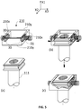
- FIG 4 shows two embodiments of drawer frames (210) which have in common that the cavity can host two ladle shroud plates positioned side by side along the first transverse direction, X2.
- This geometry allows engaging in the drawer frame a ladle shroud (111) and a collector nozzle (110).
- a collector nozzle (110) comprises an inlet portion comprising a plate with a planar upstream surface, and a tubular portion which is very short. A bore extends from the upstream surface to the end of the short tubular portion.
- the same resilient means according to the first embodiment and as discussed with respect to Figure 5 are represented in Figure 4(a) &(b).
- Figure 4(c) &(d) show a second, alternative embodiment of an elastically flexible leaf fixed in cantilever at one end thereof to the longitudinal beam (210x) of the drawer frame (210) and at the opposite end to the latch (30). Again, the latch can resiliently move back and forth along the second transverse axis, X3, through apertures located in the longitudinal beams (210x).
- Figure 4(a) &(c) show the latches in their coupling position, and Figure 4(b) &(d) in their loading position.
- Figure 8 shows a drawer frame (210) devoid of any latches (30), the latches being mounted on the support frame (211) below the top sliding surface of the two bottom guiding rails (117).
- the drawer frame (210) is of very simple construction. This is particularly true for a drawer frame (210) designed for hosting a single ladle shroud and no collector nozzle (this is not the case in Figure 8 ). Regardless of whether for one or two nozzles, such drawer frame is nonetheless useful because a hydraulic arm (40b) can be coupled to one of the transverse beams (210y) for sliding the drawer frame in and out of its casting position (cf. Figure 3(a)&(b) ). It is not so easy to couple the hydraulic arm (40b) directly to a ladle shroud.
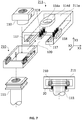
- Figures 5 to 8 show the interactions with one another of a ladle shroud (111), optionally a collector nozzle (110), a drawer frame (210) and a support frame (211) which is slidingly coupled to a ladle as explained supra.
- the drawer frame (210) is engaged into the T-passage (120) of the support frame with the longitudinal beams (210x) of the drawer frame (210) resting on the guiding rails (117).
- a hydraulic arm (40b) to a transverse beam (210y) of the drawer frame (210)
- the latter can be moved in and out of its casting position by sliding along the guiding rails (117).
- a drawer frame capable of hosting both a ladle shroud (111) and a collector nozzle (110) as illustrated in Figures 7 &8, it can be loaded in the drawer frame (210) before or after engaging the drawer frame (210) into the T-passage (120). Once the drawer frame (210) is engaged in the T-passage it is moved to a receiving position, wherein a ladle shroud (111) can be loaded up from the bottom into its corresponding position in the cavity defined by the drawer frame (210) and hung between the resilient latches (30).
- the drawer frame hosts a collector nozzle (110) too, as illustrated in Figures 7 &8, when the drawer frame (210) is in its receiving position, the collector nozzle (110) is preferably resting on the pushers (118) or rockers. This configuration illustrated in Figure 3(c) permits to reduce the size of the support frame (211).
- the drawer frame (210) In its receiving position in the T-passage, the drawer frame (210) is ready for receiving a ladle shroud (111) in the cavity as explained supra, by pushing it up with a robot (20) or other handling tool, through the resilient latches (30) until the trailing edges (3d) of the upstream protrusions (3) rest on the upstream surfaces (30u) of the latches, and the ladle shroud safely hangs below the ladle (10) in an idle position.
- the drawer frame (210) together with the ladle shroud (111) engaged in the cavity thereof can be moved to their casting position wherein the bore (115) of the ladle shroud is in registry with the opening (114a) of the bottom gate plate (114d).
- Figures 7 &8 only differ from one another in the position of the resilient latches (30): in Figure 7 they are engaged in openings provided in the longitudinal walls (210x) of the drawer frame (210), and in Figure 8 they are mounted on the support frame, below the guiding rails (117) and beside the pushers (118) in the longitudinal direction, X1.
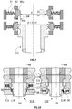
- Figure 10(a) shows an embodiment with latches mounted on the drawer frame (210)
- Figure 10(b) shows an embodiment with latches mounted on the support frame.
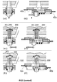
- Figure 3 illustrates a number of process steps possible with a coupling assembly according to the present invention.
- X1, X3 two cut views are showed along two orthogonal planes (X1, X3) and (X1, X2), referred to with the numerals 1 and 2, respectively.
- each step is referred to by its letter only without specifying the numeral 1 or 2, unless referring to a particular view.
- Figure 3(a) refers to both Figure 3(a1) and Figure 3(a2) .
- Figure 3(a) shows the bottom floor of a ladle (11) comprising an inner nozzle (113) in contact with a top gate plate (114u) such that the bore (113a, 113b) of the inner nozzle is in fluid communication with the through opening of the top gate plate.
- a support frame is coupled to the ladle (11) such that the opening (114a) of the bottom gate (114d) is out of registry with the through opening of the top gate plate (114u).
- the support frame (211) with bottom gate plate (114d) can slide by means of a hydraulic arm (40a) such as to bring the opening (114a) of the bottom gate plate (114d) in and out of registry with the through opening of the top gate plate (114u).
- a drawer frame (210) loaded with a collector nozzle (110) is shown separate from the support frame (211). The collector nozzle (110) can be loaded on the drawer frame (210) before or after the latter is engaged in the T-passage of the support frame (211).
- FIG. 3(b) the drawer frame (210) is inserted into the T-passage (120).
- a transverse beam (210y) is coupled to a hydraulic arm (40b).
- the hydraulic arm (40b) moves the drawer frame (210) to its receiving position, ready to receive a ladle shroud (111) and with the collector nozzle (110) resting on the pushers (118) with the bore thereof in registry with the opening (114a) of the bottom gate (114d).
- a ladle shroud (111) is brought below the support frame and drawer frame with a robot (20) or any other handling tool.
- Figure 3(e) shows a particular technique discussed in the introductory section above and traditionally used to prevent stagnant metal melt from freezing in the bore of the inner nozzle (113) prior to initiating casting.
- a plugging material usually sand.
- some molten metal percolates a short distance through the sand bed (300) and freezes forming a solid cap (301) made of a mixture of sand particles and solid metal, thus preventing molten metal (200) from flowing through the bore inlet (113a).
- the crust forming the cap (301) is sufficiently thick to resist the pressure of the molten metal and seals the bore inlet (113a) of the inner nozzle so that the casting process cannot start. It is therefore necessary to break such cap with a tool.
- a torch (21) is inserted from below into the bore of a collector nozzle (110) and used to melt the crust of the cap (301).
- the collector nozzle is nested in the conically tapering bore of the ladle shroud as shown in Figure 1(b) . Because of the length of the tubular portion of the ladle shroud, this must first be removed from the collector nozzle before a torch (21) can be inserted to melt the crust (301) to initiate flow of molten metal through the collector nozzle. At this stage the ladle shroud must rapidly be re-inserted over the collector nozzle to shield the flowing metal from oxygen. This operation is very cumbersome and dangerous as spilling of molten metal is inevitable upon re-insertion of the ladle shroud during flow of molten metal.
- the ladle shroud (111) and collector nozzle (110) are aligned side by side in the drawer frame (210).
- the collector nozzle (110) can be brought to casting position by sliding the drawer frame (210) with the hydraulic arm (40b) (cf. Figure 3(g) ). This operation brings the ladle shroud (111) to its idle position, such that it is held by the latches (30) only (cf. Figure 3(g2) &(h2)). Access to the bore of the inner nozzle is very easy through the collector nozzle (110).
- molten metal can flow through the inner nozzle (113), gate (114u, 114d) and collector nozzle (110).
- the hydraulic arm (40b) can be activated to slide the drawer frame (210) to bring the ladle shroud (111) back to its casting position. Casting of molten metal into a tundish can thus be started easily, rapidly, and with no spilling of molten metal as the ladle shroud (111) is brought to its casting position. The danger of such operation has thus been substantially reduced compared with traditional metallurgic installations.
- the coupling assembly of the present invention comprising a support frame (211), a drawer frame (210), and a ladle shroud (111) as defined above allows a very clean and reproducible casting operation from a ladle (11).
- This assembly is also advantageous in that many operations can be automated and controlled by a central processing unit (CPU), thus further increasing the security level of such operations.
- CPU central processing unit
Landscapes
- Engineering & Computer Science (AREA)
- Mechanical Engineering (AREA)
- Casting Support Devices, Ladles, And Melt Control Thereby (AREA)
- Continuous Casting (AREA)
- Molds, Cores, And Manufacturing Methods Thereof (AREA)
Claims (16)
- Schattenrohr (111) zum Gießen von Metall aus einer Gießpfanne, wobei die Düse umfasst:(a) eine Bohrung (115) die sich parallel zu einer ersten Längsachse, X1, von einer Einlauföffnung (115a) zu einer Auslauföffnung (115b) erstreckt,(b) einen Einlaufabschnitt, der sich an einem stromaufwärtigen Ende des Schattenrohrs befindet und aus einer Platte besteht, die umfasst:- eine planare stromaufwärtige Oberfläche (2u), die senkrecht zur Längsachse, X1, verläuft, wobei die stromaufwärtige Oberfläche die Einlauföffnung (115a) umfasst und durch einen stromaufwärtigen Umfang (2p) definiert ist,- eine stromabwärtige Oberfläche (4d), die durch einen stromabwärtigen Umfang (4p) definiert ist und von der stromaufwärtigen Oberfläche getrennt ist durch- eine Umfangswand, die sowohl an den stromaufwärtigen (2p) als auch den stromabwärtigen (4p) Umfang angrenzt, die die Dicke der Platte auf der Ebene des stromaufwärtigen Umfangs (2p) definiert, unddie mindestens einen ersten und einen zweiten Greifabschnitt umfasst, die voneinander durch die Bohrung (115) getrennt sind,(c) einen rohrförmigen Abschnitt, der sich entlang der ersten Längsachse, X1, von der stromabwärtigen Oberfläche (4d) des Einlaufabschnitts zu einem stromabwärtigen Ende, entgegengesetzt vom stromaufwärtigen Ende, erstreckt, undwo sich die Auslauföffnung (115b) befindet,
dadurch gekennzeichnet dass jeder des ersten und zweiten Greifabschnitts der Umfangswand einen stromaufwärtigen Vorsprung (3) umfasst, der an einem stromaufwärtigen Steg (3r) endet, der eine Vorderkante (3u), die dem stromaufwärtigen Ende der Schattenrohr zugewandt ist, von einer Hinterkante (3d) trennt, die dem stromabwärtigen Ende der Schattenrohrs zugewandt ist, und der über die gesamte Umfangswand des entsprechenden Greifabschnitts vorragt, wobei sich die stromaufwärtigen Abschnitte (3) parallel zur stromaufwärtigen Oberfläche (2u) und symmetrisch zueinander hinsichtlich der Längsachse, X1, entlang dem entsprechenden ersten und zweiten Greifabschnitt erstrecken, und dass- die Vorderkante (3u) mit einer Ebene, die parallel zur stromaufwärtigen Oberfläche verläuft, einen Winkel, α1, bildet und- die Hinterkante (3d) mit einer Ebene, die parallel zur stromaufwärtigen Oberfläche (2u) verläuft, einen Winkel, β1, bildet, wobei |α1| ≥ |β1]. - Schattenrohr nach Anspruch 1, wobei die Umfangswand einen dritten und einen vierten Greifabschnitt umfasst, die voneinander durch die Bohrung (115) getrennt sind, wobei der dritte und vierte Greifabschnitt die gleiche Geometrie und Abmessungen aufweisen wie der erste und zweite Greifabschnitt, und der dritte und vierte Greifabschnitt aneinandergrenzend quer zum ersten und zweiten Greifabschnitt verlaufen und sie einen stromaufwärtigen Vorsprung (3) der gleichen Geometrie umfassen wie der des ersten und des zweiten Greifabschnitts.
- Schattenrohr nach Anspruch 1 oder 2, wobei α1 im Bereich von 45 und 70°, vorzugsweise zwischen 55 und 65° liegt und wobei β1 vorzugsweise im Bereich von 25 und 45°, und besonders bevorzugt im Bereich von 35 und 40° liegt.
- Schattenrohr nach einem der vorhergehenden Ansprüche, wobei in jedem des ersten und zweiten Greifabschnitts:- die Distanz, Hu, vom stromaufwärtigen Steg (3r) des stromaufwärtigen Vorsprungs (3) zum unteren Teil der Vorderkante (3u), gemessen entlang einer parallel zur stromaufwärtigen Oberfläche verlaufenden Ebene, größer als 5 mm ist und vorzugsweise im Bereich von 6 bis 15 mm, und noch bevorzugter im Bereich von 8 bis 12 mm liegt, und- die Distanz, Hd, vom stromaufwärtigen Steg (3r) des stromaufwärtigen Vorsprungs (3) zum unteren Teil der Hinterkante (3d), gemessen entlang einer parallel zur stromaufwärtigen Oberfläche verlaufenden Ebene, gleich oder verschieden von Hu ist und größer als 5 mm ist und vorzugsweise im Bereich von 6 bis 15 mm, und noch bevorzugter im Bereich von 8 bis 12 mm liegt.
- Schattenrohr nach einem der vorhergehenden Ansprüche, wobei jeder des ersten und zweiten Greifabschnitts weiterhin einen stromabwärtigen Vorsprung (4) umfasst, der an einem stromabwärtigen Steg (4r) endet, der eine Vorderkante (4u), die dem stromaufwärtigen Vorsprung (3) zugewandt ist, von der stromabwärtigen Oberfläche (4d) trennt, und der parallel zum stromaufwärtigen Vorsprung (3) entlang des entsprechenden ersten und zweiten Greifabschnitts verläuft, wobei der stromaufwärtige Steg (3r) und der stromabwärtige Steg (4r) durch eine Aussparung voneinander getrennt sind.
- Schattenrohr nach einem der vorhergehenden Ansprüche, wobei die Abschnitte des stromaufwärtigen Umfangs (2p) und des stromabwärtigen Umfangs (4p), die jedem des ersten und des zweiten Greifabschnitts entsprechen, gerade Linien sind.
- Satz von Teilen zur fluidischen Verbindung eines Schattenrohrs (111) nach einem der vorhergehenden Ansprüche mit der Auslauföffnung (113b) einer inneren Düse (113) einer Gießpfanne (11), an der äußeren Oberfläche des unteren Bodens der Gießpfanne, wobei der Satz von Teilen umfasst:(a) eine Schubladenzarge (210), umfassend zwei Längsträger (210x), die entlang einer ersten Querachse, X2, verlaufen und voneinander durch zwei Querträger (210y) getrennt sind, wodurch ein Hohlraum eines Bereichs und Umfangs definiert wird, der zur passgenauen Aufnahme des Äquivalents von mindestens einer Einlaufoberfläche (2u) eines Schattenrohrs (111) nach einem der vorhergehenden Ansprüche geeignet ist, wobei die Quer- und Längsträger so angeordnet sind, dass sie eine Außenkontur bilden, die mit einem Rechteck umschrieben werden kann, das eine longitudinale Länge aufweist, die entlang einer ersten Querachse, X2, gemessen wird, und eine Querbreite aufweist, die entlang einer zweiten Querachse, X3, gemessen wird, die senkrecht zur ersten Querachse, X2 verläuft,(b) eine obere Verschlussplatte (114u), die eine planare obere Oberfläche und eine planare untere Oberfläche umfasst, die parallel zur planaren oberen Oberfläche verläuft und durch die Dicke der oberen Verschlussplatte davon getrennt ist, und die mit einer Durchgangsöffnung versehen ist, die sich durch die Dicke der oberen Verschlussplatte von der planaren oberen Oberfläche zur planaren unteren Oberfläche erstreckt, wobei die obere Verschlussplatte (114u) geeignet ist, um stationär mit der äußeren Oberfläche des unteren Bodens einer Gießpfanne (11) verbunden zu werden, wobei die Durchgangsöffnung mit der Austrittsöffnung (113b) der inneren Düse (113) in fluider Verbindung steht,(c) einen Stützrahmen (211), der geeignet ist, um mit der äußeren Oberfläche des unteren Bodens einer Gießpfanne (11) verbunden zu werden, so dass sie von einer Verschlussstellung in eine Gießstellung geschoben werden kann, wobei der Stützrahmen umfasst:- eine obere Platte (211u) mit einer oberen planaren Oberfläche, die senkrecht zu einer Längsachse, X1, verläuft, die senkrecht sowohl zu einer ersten als auch zu einer zweiten Querachse, X2, X3, verläuft, und die eine Öffnung umfasst, die passgenau eingeschlossen ist,- eine untere Verschlussplatte (114d) mit einer oberen Oberfläche, die leicht über der oberen planaren Oberfläche (211u) des Stützrahmens (211) vorsteht, und einer unteren Oberfläche, die parallel zur oberen Oberfläche verläuft und davon durch die Dicke der unteren Verschlussplatte getrennt ist, wobei die untere Verschlussplatte mit einer Öffnung (114a) versehen ist, die sich durch die Dicke der unteren Verschlussplatte erstreckt und parallel zur Längsachse, X1, verläuft, und wobei, wenn der Stützrahmen mit der Gießpfanne verbunden ist, die obere Oberfläche der unteren Verschlussplatte (114d) parallel zur unteren Oberfläche der oberen Verschlussplatte (114u) verläuft und mit ihr in gleitendem Kontakt ist, sodass, nach Schieben des Stützrahmens (211) aus seiner Verschlussstellung in seine Gießposition, die Öffnung (114a) der unteren Verschlussplatte von einer Position, in der sie von der Durchgangsöffnung der oberen Verschlussplatte (114u) verschlossen ist, in eine Position verschoben wird, in der sie mit der Durchgangsöffnung der oberen Verschlussplatte in fluider Verbindung steht,- zwei Führungsschienen (117), die sich entlang der ersten Querachse, X2, und parallel zur oberen planaren Oberfläche der oberen Platte (211u) erstrecken und voneinander durch einen Zwischenraum getrennt sind, der eine Breite hat, die entlang der zweiten Querachse, X3, gemessen wird, die kleiner ist als die Querbreite des Rechtecks, mit dem die Außenkontur der Schubladenzarge (210) umschrieben wird, und die mindestens lokal größer ist als die Breite, die entlang der zweiten Querachse, X3, des in der Schubladenzarge definierten Hohlraums gemessen wird;- einen T-förmigen Durchgang (120), der sich von einem Rahmeneinlauf entlang der ersten Querachse, X2, erstreckt, wobei die Öffnung geeignet ist, um eine Schubladenzarge (210) aufzunehmen und diese entlang des Durchgangs auf den beiden Führungsschienen (117) zu verschieben,- zwei Satz Schieber (118) oder Wippen, die neben den zwei unteren Führungsschienen auf beiden Seiten des Zwischenraums auf der Ebene der unteren Verschlussplatten-Öffnung platziert sind,dadurch gekennzeichnet, dass der Satz von Teilen weiterhin einen ersten und zweiten Riegel (30) umfasst, wobei, wenn die Schubladenzarge (210) in den Durchgang (120) des Stützrahmens (211) eingeführt ist, der erste und zweite Riegel- einander auf beiden Seiten des Zwischenraums, der zwischen den Führungsschienen gebildet wird, zugewandt sind,- eine abgeschrägte stromaufwärtige Oberfläche (30u) aufweisen, die einen Winkel, β1, mit einer Ebene bildet, die parallel zur ersten und zweiten Querachse, X2-X3, verläuft, wobei dieser dem Winkel, β1, entspricht, der durch die Hinterkante (3d) des stromaufwärtigen Vorsprungs (3) eines Schattenrohrs (111) entsprechend einem der vorhergehenden Ansprüche gebildet wird,- eine abgeschrägte stromabwärtige Oberfläche (30d) aufweisen, die einen Winkel, α1, mit einer Ebene bildet, die parallel zur ersten und zweiten Querachse, X2-X3, verläuft, wobei dieser dem Winkel, α1, entspricht, der durch die Vorderkante (3u) des stromaufwärtigen Vorsprungs (3) eines Schattenrohrs (111) entsprechend einem der vorhergehenden Ansprüche gebildet wird, und- entlang der zweiten Querachse, X3, hin und zurück verschieblich sind von einer Kopplungsstellung, in der der erste und der zweite Riegel am dichtesten zueinander sind und die stromaufwärtigen und stromabwärtigen abgeschrägten Oberflächen des ersten und zweiten Riegels im Zwischenraum zwischen den beiden Führungsschienen hervorstehen, in eine Ladestellung, in der der erste und der zweite Riegel am weitesten voneinander entfernt sind und nicht in den Zwischenraum zwischen den beiden Führungsschienen vorstehen, und- auf einem elastischen Mittel (31) angebracht sind, das natürlicherweise vorgespannt ist, um die Riegel in ihre Kopplungsstellung zu bringen.
- Satz von Teilen nach Anspruch 7, wobei die zwei Längsträger (210x) der Schubladenzarge (210) jeweils eine Öffnung umfassen, die einander zugewandt sind, durch die der erste und zweite Riegel (30) entlang der zweiten Querachse, X3, von ihrer Kopplungsstellung in ihre Ladeposition und zurück verschoben werden können.
- Satz von Teilen nach Anspruch 7, wobei der erste und der zweite Riegel (30) auf dem Stützrahmen unterhalb der zwei unteren Führungsschienen (117) befestigt sind und in Bezug auf die Schieber (118) oder Wippen in der ersten Querrichtung, X2, versetzt sind.
- Satz von Teilen nach einem der Ansprüche 7 bis 9, wobei jedes elastische Mittel (31) umfasst:- (a) entweder eine Auslegerfeder, die aus einem elastisch flexiblem Blatt besteht, das an seinem einen Ende am Riegel (30) befestigt ist und am entgegengesetzten Ende entweder am entsprechenden Längsträger (210x) der Schubladenzarge (210) oder unter der oberen Gleitoberfläche der zwei unteren Führungsschienen (117) des Stützrahmens (211) befestigt ist,- (b) oder eine Spiralenfeder, vorzugsweise eine Teleskopachse (32) umschließend, wobei die Spiralenfeder mit einem Riegel verbunden ist und sandwichartig zwischen dem Riegel (30) und einem Verschluss angeordnet ist, die in einem konstanten Abstand entlang der zweiten Querachse, X3, von den entsprechenden Führungsschienen (117) angebracht sind.
- Satz von Teilen nach einem der Ansprüche 7 bis 10, wobei die Fläche und der Umfang des Hohlraums, der durch die zwei Längsträger (210x) und die zwei Querträger (210y) definiert wird, dazu geeignet sind, das Äquivalent von zwei Einlaufoberflächen (2u) von Schattenrohren (111) nach einem der Ansprüche 1 bis 6, die nebeneinander entlang der ersten Querachse, X2, positioniert sind, passgenau aufzunehmen.
- Kit von Teilen nach Anspruch 11, weiterhin umfassend ein Schattenrohr (111) nach einem der Ansprüche 1 bis 6, und eine Kollektordüse (110), wobei die Kollektordüse (110) eine planare stromaufwärtige Oberfläche aufweist, die eine Einlauföffnung umfasst und durch einen stromaufwärtigen Umfang so definiert ist,
dass der stromaufwärtige Umfang (2p) des Schattenrohrs und der stromaufwärtige Umfang der Kollektordüse (110) passgenau in den Hohlraum der Schubladenzarge (210) passen, wenn das Schattenrohr und die Kollektordüse nebeneinander entlang der ersten Querachse, X2, ausgerichtet werden. - Metallgießanlage, umfassend eine Gießpfanne (11), die einen unteren Boden mit einer inneren Düse (113) aufweist, die mit einer Auslauföffnung (113b) versehen ist, die in fluider Verbindung mit der Durchgangsöffnung einer oberen Verschlussplatte (114u) steht, wie in Anspruch 7(b) definiert, und die mit den zusammengesetzten Elementen eines Satzes von Teilen nach einem der Ansprüche 7 bis 12 ausgerüstet ist, umfassend:(a) einen Stützrahmen (211), wie in Anspruch 7(c) definiert, der verschieblich mit einer planaren unteren Oberfläche der oberen Verschlussplatte (114u) gekoppelt ist, so dass die Öffnung (114a) der unteren Verschlussplatte (114d) mittels eines ersten hydraulischen Arms (40a) in und außer Passung mit der Durchgangsöffnung der oberen Verschlussplatte (114u) gebracht werden kann,(b) ein Schattenrohr (111) nach einem der Ansprüche 1 bis 6, wobei der Abstand, der den stromaufwärtigen Steg (3r) des stromaufwärtigen Vorsprungs (3) des ersten Greifabschnitts von dem des zweiten Greifabschnitts trennt, d + 2Hd beträgt, wobei Hd der Abstand vom stromaufwärtigen Steg (3r) des stromaufwärtigen Vorsprungs (3) zum unteren Teil der Hinterkante (3d) ist, und zwar gemessen entlang einer Ebene, die parallel zur stromaufwärtigen Oberfläche (2u) verläuft, wobei das Schattenrohr (111) lösbar gekoppelt ist mit(c) einer Schubladenzarge (210), wie in Anspruch 7(a) definiert, die im T-förmigen Durchgang (120) des Stützrahmens (211) so eingeführt ist, dass die Schubladenzarge (210) durch den T-förmigen Durchgang entlang der ersten Querachse, X2, mittels eines zweiten hydraulischen Arms (40b) hin und zurück verschoben werden kann, und wobei(d) der erste und der zweite Riegel (30) so angebracht sind, dass sie von ihrer Kopplungsstellung, in der sie entlang der zweiten Querachse, X3, um eine d entsprechende Distanz von einander getrennt sind, in ihre Ladestellung verschoben werden können, in der sie voneinander entlang der zweiten Querachse, X3, um einen d + 2Hd entsprechenden Abstand getrennt sind,(e) einen Roboter oder ein Handhabungswerkzeug (20), das zum Festhalten des Schattenrohrs (111) geeignet ist, um dieses unter den Stützrahmen (211) auf die Höhe der Riegel (30) zu bringen und dessen Einlaufabschnitt nach oben durch die Riegel zu drücken, indem das elastische Mittel (31) verformt wird, bis die Riegel unterhalb der stromaufwärtigen Vorsprünge (3) des Schattenrohrs eingreifen, wodurch die Kopplungsstellung erreicht wird, wobei die Hinterkanten (3d) der stromaufwärtigen Vorsprünge (3) passgenau auf den planaren abgeschrägten stromaufwärtigen Oberflächen (30u) der entsprechenden Riegel (30) aufliegen,wobei die Schubladenzarge (210) durch Bewegung durch den T-förmigen Durchgang (120) des Stützrahmens entlang der ersten Querachse, X2, die Bohrung (115) des Schattenrohrs (111) alternativ in und außer Passung mit der Öffnung (114a) der unteren Veschlussplatte (114d) bringen kann, wobei die Schieber (118) auf die stromabwärtige Oberfläche (4d) des Schattenrohrs (111) drücken, wenn die Bohrung (115) des Schattenrohrs (111) in Passung mit der Öffnung (114a) der unteren Verschlussplatte (114d) ist.
- Metallgießanlage nach Anspruch 13, wobei die Schubladenzarge (210) wie in Anspruch 12 definiert beschaffen ist und so mit einer Kollektordüse (110) bestückt ist, dass die Bewegung der Schubladenzarge (210) durch den Durchgang des Stützrahmens entlang der ersten Querachse, X2, alternativ die Bohrung (115) des Schattenrohrs (111) oder die Bohrung der Kollektordüse (110) in und außer Passung mit der Öffnung (114a) der unteren Verschlussplatte (114) bringen kann.
- Verfahren zum Gießen von geschmolzenem Metall aus einer Gießpfanne (11) in einen Gießverteiler (10) oder ein anderes metallurgisches Gefäß, umfassend die folgenden Schritte:(a) Verbringen einer Gießpfanne (11), die geschmolzenes Metall enthält und mit einem Stützrahmen (211), wie in Anspruch 7(c) definiert, sowie mit einer Schubladenzarge (210), wie in Ansprüchen 7(a) oder 8 definiert, ausgerüstet ist, über einen Gießverteiler (10) oder ein anderes metallurgisches Gefäß,(b) Verbringen eines Schattenrohrs (111) mit einem Roboter (20) oder anderen Handhabungswerkzeug unter den Stützrahmen (211) auf die Höhe der Riegel (30),(c) Forcieren, mit dem Roboter (20) oder anderen Handhabungswerkzeug, des Einlaufabschnitts des Schattenrohrs (111) nach oben in den Hohlraum der Schubladenzarge (210) durch die Riegel durch Verformung des elastischen Mittels (31), bis die Riegel eingreifen und das Schattenrohr seine Kopplungsstellung erreicht, in der die Hinterkanten (3d) der ersten Vorsprünge (3) passgenau auf der planaren abgeschrägten stromaufwärtigen Oberfläche (30u) jeder der entsprechenden Riegel (30) aufliegen,(d) Bewegung der Schubladenzarge (210) mit einem ersten hydraulischen Arm (40b), um die Bohrung (115) des Schattenrohrs (111) in Passung mit der Öffnung (114a) der unteren Veschlussplatte (114d) zu bringen, wobei die Schieber (118) auf die stromabwärtige Oberfläche des Schattenrohrs (111) drücken,(e) Bewegung des Stützrahmens (211) mit einem zweiten hydraulischen Arm (40a) in eine Gießposition, so dass die Öffnung (114a) der unteren Verschlussplatte (114d) in Passung mit der Durchgangsöffnung der oberen Verschlussplatte (114u) ist, so dass in der Gießpfanne (11) enthaltenes Schmelzmetall durch das Schattenrohr fließen kann.
- Verfahren nach Anspruch 15, weiterhin umfassend die folgenden Schritte:(a) wenn das Gießen des Schmelzmetalls aus der Gießpfanne beendet ist, Bewegen des Stützrahmens (211) mit dem zweiten hydraulischen Arm (40a) in eine Verschlussstellung, so dass die Öffnung (114a) der unteren Verschlussplatte (114d) außer Passung mit dem Durchgang der oberen Verschlussplatte (114u) ist,(b) Bewegen der Schubladenzarge (2100 mit dem ersten hydraulischen Arm (40b), um das Schattenrohr (111) von den Schiebern (118) zu entfernen, so dass es nur an den Riegeln (30) hängt,(c) mit einem Roboter (20) oder anderen Handhabungswerkzeug, Forcieren des Schattenrohrs (111) nach unten durch die Riegel durch Verformung des elastischen Mittels (31), bis die Gießpfannendüse von der Schubladenzarge (210) ausgekuppelt ist und Entfernen des Schattenrohrs (111); und(d) Entfernen der Gießpfanne (11).
Priority Applications (1)
| Application Number | Priority Date | Filing Date | Title |
|---|---|---|---|
| PL15705020T PL3107671T3 (pl) | 2014-02-19 | 2015-02-17 | Wylew kadzi głównej do odlewania metalu, zestaw części do zespołu łączącego do łączenia wymienionego wylewu kadzi głównej z kadzią główną, instalacja do odlewania metalu i proces łączenia |
Applications Claiming Priority (2)
| Application Number | Priority Date | Filing Date | Title |
|---|---|---|---|
| EP14155819 | 2014-02-19 | ||
| PCT/EP2015/053313 WO2015124567A1 (en) | 2014-02-19 | 2015-02-17 | Ladle shroud for casting metal, kit of parts for coupling assembly for coupling said ladle shroud to a ladle, metal casting installation and coupling process |
Publications (2)
| Publication Number | Publication Date |
|---|---|
| EP3107671A1 EP3107671A1 (de) | 2016-12-28 |
| EP3107671B1 true EP3107671B1 (de) | 2018-08-22 |
Family
ID=50230853
Family Applications (1)
| Application Number | Title | Priority Date | Filing Date |
|---|---|---|---|
| EP15705020.4A Active EP3107671B1 (de) | 2014-02-19 | 2015-02-17 | Pfannenschutzrohr zum giessen von metall, bausatz für kupplungsanordnung zum befestigen des pfannenschutzrohrs an einer pfanne, metallgiesseinrichtung und kupplungsverfahren |
Country Status (16)
| Country | Link |
|---|---|
| US (1) | US10052687B2 (de) |
| EP (1) | EP3107671B1 (de) |
| JP (1) | JP6523315B2 (de) |
| KR (1) | KR102339331B1 (de) |
| CN (1) | CN106457376B (de) |
| AR (1) | AR099467A1 (de) |
| AU (1) | AU2015220946B2 (de) |
| BR (1) | BR112016017329B1 (de) |
| CA (1) | CA2939039C (de) |
| ES (1) | ES2698526T3 (de) |
| MX (1) | MX392519B (de) |
| PL (1) | PL3107671T3 (de) |
| RU (1) | RU2687115C2 (de) |
| TW (1) | TWI647029B (de) |
| UA (1) | UA118367C2 (de) |
| WO (1) | WO2015124567A1 (de) |
Families Citing this family (10)
| Publication number | Priority date | Publication date | Assignee | Title |
|---|---|---|---|---|
| AR099467A1 (es) * | 2014-02-19 | 2016-07-27 | Vesuvius Group Sa | Revestimiento de cuchara de colada para colada de metales, conjunto de partes de conjunto de acoplamiento para acoplar dicho revestimiento de cuchara de colada a una cuchara, instalación de colada de metales y proceso de acoplamiento |
| JP6663230B2 (ja) * | 2016-01-25 | 2020-03-11 | 黒崎播磨株式会社 | ノズル構造体 |
| CN210231514U (zh) | 2017-11-10 | 2020-04-03 | 维苏威集团有限公司 | 自锁式内管口系统 |
| CN109877306B (zh) | 2017-11-10 | 2021-12-24 | 维苏威集团有限公司 | 包括卡口式自由集液管口的底板组件 |
| KR102139631B1 (ko) * | 2018-07-11 | 2020-07-30 | 주식회사 포스코 | 슬라이드 게이트 장치 및 이를 이용한 주조 방법 |
| KR102701980B1 (ko) * | 2019-09-18 | 2024-09-02 | 엘지전자 주식회사 | 액체통에 담긴 액체의 수위를 산출하는 로봇 및 방법 |
| CN113333730B (zh) * | 2020-02-18 | 2025-07-11 | 维苏威集团有限公司 | 金属浇铸设备 |
| KR20220155428A (ko) * | 2020-03-31 | 2022-11-22 | 베수비우스 그룹, 에스. 에이. | 조작기가 내장된 로봇화된 레이들 수송 장치 시스템 |
| CN115351270B (zh) * | 2022-06-28 | 2024-06-11 | 东北大学 | 一种中间包底部电磁旋流水口设备的固定装置 |
| CN119747636B (zh) * | 2024-12-31 | 2025-11-21 | 湖南瓦特曼机器人科技有限公司 | 一种用于钢包热修的下水口自动拆装方法 |
Family Cites Families (24)
| Publication number | Priority date | Publication date | Assignee | Title |
|---|---|---|---|---|
| SU872014A1 (ru) * | 1979-10-10 | 1981-10-15 | Центральный научно-исследовательский институт черной металлургии им.И.П.Бардина | Устройство дл подвода металла |
| US4262827A (en) * | 1979-12-26 | 1981-04-21 | Bethlehem Steel Corporation | Ladle shroud apparatus |
| BE1007317A3 (fr) * | 1993-07-27 | 1995-05-16 | Int Ind Eng Sa | Dispositif d'amenee et d'echange d'un tube de coulee dans une installation de coulee continue a brames minces. |
| JP3212071B2 (ja) | 1995-10-20 | 2001-09-25 | 東芝セラミックス株式会社 | 浸漬ノズルのハンドリング装置 |
| FR2742684B1 (fr) * | 1995-12-26 | 1998-04-30 | Vesuvius France Sa | Tiroir de changement de plaques pour un conteneur metallurgique et jeu de plaques pour ce tiroir |
| JP3168157B2 (ja) * | 1996-01-23 | 2001-05-21 | 住友重機械工業株式会社 | 連続鋳造機のロングノズル着脱装置 |
| WO2004052576A1 (en) * | 2002-12-10 | 2004-06-24 | Vesuvius Group S.A. | Metallic frame for a pouring nozzle, assembly of a metallic frame with a pouring nozzle and device for the insertion and/or removal of a pouring nozzle |
| JP4342967B2 (ja) * | 2004-01-27 | 2009-10-14 | 品川白煉瓦株式会社 | 連続鋳造用浸漬ノズル |
| JP4604092B2 (ja) * | 2008-01-07 | 2010-12-22 | 品川リフラクトリーズ株式会社 | 浸漬ノズル支持交換機構及び下ノズル/浸漬ノズルのシール方法 |
| NZ593480A (en) * | 2008-11-20 | 2013-02-22 | Vesuvius Group Sa | Casting pipe, device for handling said pipe and valve driving device to allow continuous oxidiation free casting |
| JP5324662B2 (ja) * | 2008-11-20 | 2013-10-23 | ベスビウス グループ ソシエテ アノニム | 取瓶シュラウドを取り扱うための支持ヘッド |
| AR074355A1 (es) * | 2008-11-20 | 2011-01-12 | Vesuvius Group Sa | Elemento de colada reutilizable y procedimiento de colada |
| JP2010221279A (ja) * | 2009-03-24 | 2010-10-07 | Kurosaki Harima Corp | 連続鋳造用ノズルの支持装置及び支持方法並びにスライディングノズル設備及び連続鋳造用ノズル |
| ES2364737T3 (es) * | 2009-07-01 | 2011-09-13 | REFRACTORY INTELLECTUAL PROPERTY GMBH & CO. KG | Boquilla de colada. |
| CN102791403B (zh) * | 2009-10-21 | 2016-05-25 | 斯托品克股份公司 | 用于在用于金属熔融物的容器的注出口处的滑盖的耐火单元 |
| EP2368654A1 (de) * | 2010-03-19 | 2011-09-28 | Vesuvius Group S.A | Halte- und Wechselvorrichtung einer Gespannplatte in einer Gießanlage, Metallmantel der Gespannplatte und Gespannplatte, die mit Mitteln zum Anschluss an einen Sensor der Vorrichtung ausgestattet ist |
| EP2386368A1 (de) * | 2010-03-19 | 2011-11-16 | Vesuvius Group S.A | Interne Düse für den Transfer von flüssigem Metall in einem Behälter, Einspannsystem für diese Düse und Ausflussvorrichtung |
| EP2368655A1 (de) | 2010-03-19 | 2011-09-28 | Vesuvius Group S.A | Platte für den Transfer von flüssigem Metall aus einem metallurgischen Behälter sowie Gestell und Wechselvorrichtung für eine solche Platte |
| JP5116852B2 (ja) * | 2010-03-30 | 2013-01-09 | 明智セラミックス株式会社 | 鋳造ノズル |
| EP2524748A1 (de) * | 2011-05-16 | 2012-11-21 | Vesuvius Group S.A | Fehlersichere Düsenaustauschvorrichtung und Düseneinheit |
| AR086749A1 (es) * | 2011-06-28 | 2014-01-22 | Vesuvius Group Sa | Dispositivo de compuerta de corte, artesa y buza de colada |
| RU2675131C2 (ru) * | 2013-10-14 | 2018-12-17 | Везувиус Груп (Са) | Соединительное устройство для двустороннего соединения защитной трубы разливочного ковша со стаканом-коллектором, самоподдерживающаяся защитная труба разливочного ковша, их узел и способ соединения защитной трубы разливочного ковша со стаканом-коллектором |
| AR099467A1 (es) * | 2014-02-19 | 2016-07-27 | Vesuvius Group Sa | Revestimiento de cuchara de colada para colada de metales, conjunto de partes de conjunto de acoplamiento para acoplar dicho revestimiento de cuchara de colada a una cuchara, instalación de colada de metales y proceso de acoplamiento |
| CA2943173A1 (en) * | 2014-05-05 | 2015-11-12 | Refractory Intellectual Property Gmbh & Co. Kg | Refractory ceramic casting nozzle |
-
2015
- 2015-02-11 AR ARP150100404A patent/AR099467A1/es active IP Right Grant
- 2015-02-11 TW TW104104491A patent/TWI647029B/zh not_active IP Right Cessation
- 2015-02-17 WO PCT/EP2015/053313 patent/WO2015124567A1/en not_active Ceased
- 2015-02-17 KR KR1020167025676A patent/KR102339331B1/ko active Active
- 2015-02-17 RU RU2016131411A patent/RU2687115C2/ru active
- 2015-02-17 US US15/120,351 patent/US10052687B2/en active Active
- 2015-02-17 EP EP15705020.4A patent/EP3107671B1/de active Active
- 2015-02-17 JP JP2016552894A patent/JP6523315B2/ja active Active
- 2015-02-17 UA UAA201608820A patent/UA118367C2/uk unknown
- 2015-02-17 BR BR112016017329-5A patent/BR112016017329B1/pt active IP Right Grant
- 2015-02-17 ES ES15705020T patent/ES2698526T3/es active Active
- 2015-02-17 AU AU2015220946A patent/AU2015220946B2/en active Active
- 2015-02-17 PL PL15705020T patent/PL3107671T3/pl unknown
- 2015-02-17 CN CN201580020442.5A patent/CN106457376B/zh active Active
- 2015-02-17 MX MX2016010695A patent/MX392519B/es unknown
- 2015-02-17 CA CA2939039A patent/CA2939039C/en active Active
Non-Patent Citations (1)
| Title |
|---|
| None * |
Also Published As
| Publication number | Publication date |
|---|---|
| CA2939039C (en) | 2022-05-03 |
| TWI647029B (zh) | 2019-01-11 |
| MX2016010695A (es) | 2016-11-08 |
| CA2939039A1 (en) | 2015-08-27 |
| UA118367C2 (uk) | 2019-01-10 |
| BR112016017329A2 (pt) | 2017-08-22 |
| CN106457376A (zh) | 2017-02-22 |
| CN106457376B (zh) | 2019-11-15 |
| KR102339331B1 (ko) | 2021-12-14 |
| RU2016131411A3 (de) | 2018-10-29 |
| US10052687B2 (en) | 2018-08-21 |
| TW201540393A (zh) | 2015-11-01 |
| KR20160124189A (ko) | 2016-10-26 |
| JP6523315B2 (ja) | 2019-05-29 |
| MX392519B (es) | 2025-03-24 |
| EP3107671A1 (de) | 2016-12-28 |
| RU2016131411A (ru) | 2018-03-20 |
| WO2015124567A1 (en) | 2015-08-27 |
| BR112016017329B1 (pt) | 2021-08-17 |
| JP2017506584A (ja) | 2017-03-09 |
| US20170066048A1 (en) | 2017-03-09 |
| AU2015220946B2 (en) | 2019-01-03 |
| RU2687115C2 (ru) | 2019-05-07 |
| ES2698526T3 (es) | 2019-02-05 |
| AU2015220946A1 (en) | 2016-08-11 |
| PL3107671T3 (pl) | 2019-01-31 |
| AR099467A1 (es) | 2016-07-27 |
Similar Documents
| Publication | Publication Date | Title |
|---|---|---|
| AU2015220946B2 (en) | Ladle shroud for casting metal, kit of parts for coupling assembly for coupling said ladle shroud to a ladle, metal casting installation and coupling process | |
| EP3057728B1 (de) | Kupplungsvorrichtung zur lösbaren kopplung eines pfannenschutzrohr an einen sammelausguss, selbsttragendes pfannenschutzrohr, kit und verfahren zur kopplung einer pfannenschutzrohrs an einen sammelausguss | |
| CA2166703A1 (en) | Replacing device for immersion nozzles | |
| AU2018363796B2 (en) | Bottom plate assembly comprising a bayonet free collector nozzle | |
| EP2723522B1 (de) | Einschluss- und ausgussbehälter für metallschmelze mit zwei ausgiessdüsen | |
| RU2561619C2 (ru) | Огнеупорный блок для шиберного затвора в сливном отверстии емкости для металлического расплава | |
| CA2825676A1 (en) | Chop gate and nozzle | |
| CA3227256A1 (en) | Mould for casting molten metal comprising a coupling mechanism for a shroud, casting installation for casting a molten metal and method for casting a molten metal | |
| CA3080409C (en) | Bottom plate assembly comprising a bayonet free collector nozzle | |
| KR20250150033A (ko) | 모래 주조 주형, 숏-슈라우드, 및 주형/슈라우드 결합 메커니즘을 포함하는 용융 금속 주조용 조립체, 용융 금속 부품 주조를 위한 주조 설비 및 방법 | |
| JP6194947B2 (ja) | スラブ連続鋳造用装置 | |
| CN1665620A (zh) | 用于从一容器中排放熔融金属的排放装置 | |
| CN1665621A (zh) | 用于从一容器中排放熔融金属的排放装置 | |
| JP2001150110A (ja) | 溶融金属排出ゲートにおけるゲートプレート仮止め用磁気吸引装置 |
Legal Events
| Date | Code | Title | Description |
|---|---|---|---|
| PUAI | Public reference made under article 153(3) epc to a published international application that has entered the european phase |
Free format text: ORIGINAL CODE: 0009012 |
|
| STAA | Information on the status of an ep patent application or granted ep patent |
Free format text: STATUS: REQUEST FOR EXAMINATION WAS MADE |
|
| 17P | Request for examination filed |
Effective date: 20160919 |
|
| AK | Designated contracting states |
Kind code of ref document: A1 Designated state(s): AL AT BE BG CH CY CZ DE DK EE ES FI FR GB GR HR HU IE IS IT LI LT LU LV MC MK MT NL NO PL PT RO RS SE SI SK SM TR |
|
| AX | Request for extension of the european patent |
Extension state: BA ME |
|
| DAX | Request for extension of the european patent (deleted) | ||
| GRAP | Despatch of communication of intention to grant a patent |
Free format text: ORIGINAL CODE: EPIDOSNIGR1 |
|
| STAA | Information on the status of an ep patent application or granted ep patent |
Free format text: STATUS: GRANT OF PATENT IS INTENDED |
|
| INTG | Intention to grant announced |
Effective date: 20180314 |
|
| GRAS | Grant fee paid |
Free format text: ORIGINAL CODE: EPIDOSNIGR3 |
|
| GRAA | (expected) grant |
Free format text: ORIGINAL CODE: 0009210 |
|
| STAA | Information on the status of an ep patent application or granted ep patent |
Free format text: STATUS: THE PATENT HAS BEEN GRANTED |
|
| RAP1 | Party data changed (applicant data changed or rights of an application transferred) |
Owner name: VESUVIUS GROUP, SA |
|
| AK | Designated contracting states |
Kind code of ref document: B1 Designated state(s): AL AT BE BG CH CY CZ DE DK EE ES FI FR GB GR HR HU IE IS IT LI LT LU LV MC MK MT NL NO PL PT RO RS SE SI SK SM TR |
|
| REG | Reference to a national code |
Ref country code: GB Ref legal event code: FG4D |
|
| REG | Reference to a national code |
Ref country code: CH Ref legal event code: EP |
|
| REG | Reference to a national code |
Ref country code: AT Ref legal event code: REF Ref document number: 1031879 Country of ref document: AT Kind code of ref document: T Effective date: 20180915 |
|
| REG | Reference to a national code |
Ref country code: IE Ref legal event code: FG4D |
|
| REG | Reference to a national code |
Ref country code: DE Ref legal event code: R096 Ref document number: 602015015077 Country of ref document: DE |
|
| REG | Reference to a national code |
Ref country code: RO Ref legal event code: EPE |
|
| REG | Reference to a national code |
Ref country code: SE Ref legal event code: TRGR |
|
| REG | Reference to a national code |
Ref country code: NL Ref legal event code: FP |
|
| REG | Reference to a national code |
Ref country code: LT Ref legal event code: MG4D |
|
| PG25 | Lapsed in a contracting state [announced via postgrant information from national office to epo] |
Ref country code: NO Free format text: LAPSE BECAUSE OF FAILURE TO SUBMIT A TRANSLATION OF THE DESCRIPTION OR TO PAY THE FEE WITHIN THE PRESCRIBED TIME-LIMIT Effective date: 20181122 Ref country code: GR Free format text: LAPSE BECAUSE OF FAILURE TO SUBMIT A TRANSLATION OF THE DESCRIPTION OR TO PAY THE FEE WITHIN THE PRESCRIBED TIME-LIMIT Effective date: 20181123 Ref country code: IS Free format text: LAPSE BECAUSE OF FAILURE TO SUBMIT A TRANSLATION OF THE DESCRIPTION OR TO PAY THE FEE WITHIN THE PRESCRIBED TIME-LIMIT Effective date: 20181222 Ref country code: RS Free format text: LAPSE BECAUSE OF FAILURE TO SUBMIT A TRANSLATION OF THE DESCRIPTION OR TO PAY THE FEE WITHIN THE PRESCRIBED TIME-LIMIT Effective date: 20180822 Ref country code: BG Free format text: LAPSE BECAUSE OF FAILURE TO SUBMIT A TRANSLATION OF THE DESCRIPTION OR TO PAY THE FEE WITHIN THE PRESCRIBED TIME-LIMIT Effective date: 20181122 Ref country code: LT Free format text: LAPSE BECAUSE OF FAILURE TO SUBMIT A TRANSLATION OF THE DESCRIPTION OR TO PAY THE FEE WITHIN THE PRESCRIBED TIME-LIMIT Effective date: 20180822 |
|
| REG | Reference to a national code |
Ref country code: ES Ref legal event code: FG2A Ref document number: 2698526 Country of ref document: ES Kind code of ref document: T3 Effective date: 20190205 |
|
| PG25 | Lapsed in a contracting state [announced via postgrant information from national office to epo] |
Ref country code: AL Free format text: LAPSE BECAUSE OF FAILURE TO SUBMIT A TRANSLATION OF THE DESCRIPTION OR TO PAY THE FEE WITHIN THE PRESCRIBED TIME-LIMIT Effective date: 20180822 Ref country code: LV Free format text: LAPSE BECAUSE OF FAILURE TO SUBMIT A TRANSLATION OF THE DESCRIPTION OR TO PAY THE FEE WITHIN THE PRESCRIBED TIME-LIMIT Effective date: 20180822 Ref country code: HR Free format text: LAPSE BECAUSE OF FAILURE TO SUBMIT A TRANSLATION OF THE DESCRIPTION OR TO PAY THE FEE WITHIN THE PRESCRIBED TIME-LIMIT Effective date: 20180822 |
|
| PG25 | Lapsed in a contracting state [announced via postgrant information from national office to epo] |
Ref country code: EE Free format text: LAPSE BECAUSE OF FAILURE TO SUBMIT A TRANSLATION OF THE DESCRIPTION OR TO PAY THE FEE WITHIN THE PRESCRIBED TIME-LIMIT Effective date: 20180822 |
|
| REG | Reference to a national code |
Ref country code: DE Ref legal event code: R097 Ref document number: 602015015077 Country of ref document: DE |
|
| PG25 | Lapsed in a contracting state [announced via postgrant information from national office to epo] |
Ref country code: SM Free format text: LAPSE BECAUSE OF FAILURE TO SUBMIT A TRANSLATION OF THE DESCRIPTION OR TO PAY THE FEE WITHIN THE PRESCRIBED TIME-LIMIT Effective date: 20180822 Ref country code: SK Free format text: LAPSE BECAUSE OF FAILURE TO SUBMIT A TRANSLATION OF THE DESCRIPTION OR TO PAY THE FEE WITHIN THE PRESCRIBED TIME-LIMIT Effective date: 20180822 Ref country code: DK Free format text: LAPSE BECAUSE OF FAILURE TO SUBMIT A TRANSLATION OF THE DESCRIPTION OR TO PAY THE FEE WITHIN THE PRESCRIBED TIME-LIMIT Effective date: 20180822 |
|
| PLBE | No opposition filed within time limit |
Free format text: ORIGINAL CODE: 0009261 |
|
| STAA | Information on the status of an ep patent application or granted ep patent |
Free format text: STATUS: NO OPPOSITION FILED WITHIN TIME LIMIT |
|
| REG | Reference to a national code |
Ref country code: AT Ref legal event code: UEP Ref document number: 1031879 Country of ref document: AT Kind code of ref document: T Effective date: 20180822 |
|
| 26N | No opposition filed |
Effective date: 20190523 |
|
| PG25 | Lapsed in a contracting state [announced via postgrant information from national office to epo] |
Ref country code: SI Free format text: LAPSE BECAUSE OF FAILURE TO SUBMIT A TRANSLATION OF THE DESCRIPTION OR TO PAY THE FEE WITHIN THE PRESCRIBED TIME-LIMIT Effective date: 20180822 |
|
| PG25 | Lapsed in a contracting state [announced via postgrant information from national office to epo] |
Ref country code: MC Free format text: LAPSE BECAUSE OF FAILURE TO SUBMIT A TRANSLATION OF THE DESCRIPTION OR TO PAY THE FEE WITHIN THE PRESCRIBED TIME-LIMIT Effective date: 20180822 |
|
| REG | Reference to a national code |
Ref country code: IE Ref legal event code: MM4A |
|
| PG25 | Lapsed in a contracting state [announced via postgrant information from national office to epo] |
Ref country code: IE Free format text: LAPSE BECAUSE OF NON-PAYMENT OF DUE FEES Effective date: 20190217 |
|
| PG25 | Lapsed in a contracting state [announced via postgrant information from national office to epo] |
Ref country code: PT Free format text: LAPSE BECAUSE OF FAILURE TO SUBMIT A TRANSLATION OF THE DESCRIPTION OR TO PAY THE FEE WITHIN THE PRESCRIBED TIME-LIMIT Effective date: 20181222 Ref country code: MT Free format text: LAPSE BECAUSE OF NON-PAYMENT OF DUE FEES Effective date: 20190217 |
|
| PG25 | Lapsed in a contracting state [announced via postgrant information from national office to epo] |
Ref country code: CY Free format text: LAPSE BECAUSE OF FAILURE TO SUBMIT A TRANSLATION OF THE DESCRIPTION OR TO PAY THE FEE WITHIN THE PRESCRIBED TIME-LIMIT Effective date: 20180822 |
|
| PG25 | Lapsed in a contracting state [announced via postgrant information from national office to epo] |
Ref country code: HU Free format text: LAPSE BECAUSE OF FAILURE TO SUBMIT A TRANSLATION OF THE DESCRIPTION OR TO PAY THE FEE WITHIN THE PRESCRIBED TIME-LIMIT; INVALID AB INITIO Effective date: 20150217 |
|
| PG25 | Lapsed in a contracting state [announced via postgrant information from national office to epo] |
Ref country code: MK Free format text: LAPSE BECAUSE OF FAILURE TO SUBMIT A TRANSLATION OF THE DESCRIPTION OR TO PAY THE FEE WITHIN THE PRESCRIBED TIME-LIMIT Effective date: 20180822 |
|
| P01 | Opt-out of the competence of the unified patent court (upc) registered |
Effective date: 20230524 |
|
| PGFP | Annual fee paid to national office [announced via postgrant information from national office to epo] |
Ref country code: LU Payment date: 20240227 Year of fee payment: 10 |
|
| PGFP | Annual fee paid to national office [announced via postgrant information from national office to epo] |
Ref country code: RO Payment date: 20240205 Year of fee payment: 10 Ref country code: CZ Payment date: 20240205 Year of fee payment: 10 |
|
| PGFP | Annual fee paid to national office [announced via postgrant information from national office to epo] |
Ref country code: NL Payment date: 20250227 Year of fee payment: 11 |
|
| PG25 | Lapsed in a contracting state [announced via postgrant information from national office to epo] |
Ref country code: LU Free format text: LAPSE BECAUSE OF NON-PAYMENT OF DUE FEES Effective date: 20250217 |
|
| PG25 | Lapsed in a contracting state [announced via postgrant information from national office to epo] |
Ref country code: CZ Free format text: LAPSE BECAUSE OF NON-PAYMENT OF DUE FEES Effective date: 20250217 |
|
| PG25 | Lapsed in a contracting state [announced via postgrant information from national office to epo] |
Ref country code: RO Free format text: LAPSE BECAUSE OF NON-PAYMENT OF DUE FEES Effective date: 20250217 |
|
| REG | Reference to a national code |
Ref country code: CH Ref legal event code: U11 Free format text: ST27 STATUS EVENT CODE: U-0-0-U10-U11 (AS PROVIDED BY THE NATIONAL OFFICE) Effective date: 20260301 |
|
| PGFP | Annual fee paid to national office [announced via postgrant information from national office to epo] |
Ref country code: SE Payment date: 20260227 Year of fee payment: 12 |
|
| PGFP | Annual fee paid to national office [announced via postgrant information from national office to epo] |
Ref country code: GB Payment date: 20260227 Year of fee payment: 12 |
|
| PGFP | Annual fee paid to national office [announced via postgrant information from national office to epo] |
Ref country code: ES Payment date: 20260302 Year of fee payment: 12 |
|
| PGFP | Annual fee paid to national office [announced via postgrant information from national office to epo] |
Ref country code: DE Payment date: 20260227 Year of fee payment: 12 |
|
| PGFP | Annual fee paid to national office [announced via postgrant information from national office to epo] |
Ref country code: AT Payment date: 20260227 Year of fee payment: 12 |
|
| PGFP | Annual fee paid to national office [announced via postgrant information from national office to epo] |
Ref country code: FI Payment date: 20260225 Year of fee payment: 12 Ref country code: BE Payment date: 20260227 Year of fee payment: 12 Ref country code: IT Payment date: 20260219 Year of fee payment: 12 |
|
| PGFP | Annual fee paid to national office [announced via postgrant information from national office to epo] |
Ref country code: FR Payment date: 20260225 Year of fee payment: 12 |
|
| PGFP | Annual fee paid to national office [announced via postgrant information from national office to epo] |
Ref country code: TR Payment date: 20260206 Year of fee payment: 12 |
|
| PGFP | Annual fee paid to national office [announced via postgrant information from national office to epo] |
Ref country code: CH Payment date: 20260301 Year of fee payment: 12 |
|
| PGFP | Annual fee paid to national office [announced via postgrant information from national office to epo] |
Ref country code: PL Payment date: 20260212 Year of fee payment: 12 |