EP3105666B1 - Terminal utilisateur et procédé d'affichage associé - Google Patents
Terminal utilisateur et procédé d'affichage associé Download PDFInfo
- Publication number
- EP3105666B1 EP3105666B1 EP15746532.9A EP15746532A EP3105666B1 EP 3105666 B1 EP3105666 B1 EP 3105666B1 EP 15746532 A EP15746532 A EP 15746532A EP 3105666 B1 EP3105666 B1 EP 3105666B1
- Authority
- EP
- European Patent Office
- Prior art keywords
- display
- exposure area
- area
- user interaction
- message
- Prior art date
- Legal status (The legal status is an assumption and is not a legal conclusion. Google has not performed a legal analysis and makes no representation as to the accuracy of the status listed.)
- Active
Links
- 238000000034 method Methods 0.000 title claims description 27
- 230000003993 interaction Effects 0.000 claims description 226
- 230000033001 locomotion Effects 0.000 claims description 24
- 230000004044 response Effects 0.000 claims description 12
- 230000006870 function Effects 0.000 description 56
- 238000004891 communication Methods 0.000 description 10
- 230000002035 prolonged effect Effects 0.000 description 7
- 238000009877 rendering Methods 0.000 description 5
- 238000010079 rubber tapping Methods 0.000 description 5
- 239000002131 composite material Substances 0.000 description 4
- 238000010586 diagram Methods 0.000 description 4
- 238000001914 filtration Methods 0.000 description 3
- 230000008569 process Effects 0.000 description 3
- 238000012545 processing Methods 0.000 description 3
- 230000003321 amplification Effects 0.000 description 2
- 230000008859 change Effects 0.000 description 2
- 238000006243 chemical reaction Methods 0.000 description 2
- 238000005516 engineering process Methods 0.000 description 2
- 238000012986 modification Methods 0.000 description 2
- 230000004048 modification Effects 0.000 description 2
- 238000012544 monitoring process Methods 0.000 description 2
- 238000003199 nucleic acid amplification method Methods 0.000 description 2
- 230000033764 rhythmic process Effects 0.000 description 2
- 210000003813 thumb Anatomy 0.000 description 2
- 238000005452 bending Methods 0.000 description 1
- 230000006835 compression Effects 0.000 description 1
- 238000007906 compression Methods 0.000 description 1
- 238000011161 development Methods 0.000 description 1
- 201000004428 dysembryoplastic neuroepithelial tumor Diseases 0.000 description 1
- 230000000694 effects Effects 0.000 description 1
- 239000004744 fabric Substances 0.000 description 1
- 239000000835 fiber Substances 0.000 description 1
- 210000003811 finger Anatomy 0.000 description 1
- 230000007774 longterm Effects 0.000 description 1
- 230000006855 networking Effects 0.000 description 1
- 238000000060 site-specific infrared dichroism spectroscopy Methods 0.000 description 1
- 230000000153 supplemental effect Effects 0.000 description 1
Images


Classifications
-
- G—PHYSICS
- G06—COMPUTING; CALCULATING OR COUNTING
- G06F—ELECTRIC DIGITAL DATA PROCESSING
- G06F3/00—Input arrangements for transferring data to be processed into a form capable of being handled by the computer; Output arrangements for transferring data from processing unit to output unit, e.g. interface arrangements
- G06F3/01—Input arrangements or combined input and output arrangements for interaction between user and computer
- G06F3/048—Interaction techniques based on graphical user interfaces [GUI]
- G06F3/0481—Interaction techniques based on graphical user interfaces [GUI] based on specific properties of the displayed interaction object or a metaphor-based environment, e.g. interaction with desktop elements like windows or icons, or assisted by a cursor's changing behaviour or appearance
- G06F3/0482—Interaction with lists of selectable items, e.g. menus
-
- G—PHYSICS
- G06—COMPUTING; CALCULATING OR COUNTING
- G06F—ELECTRIC DIGITAL DATA PROCESSING
- G06F1/00—Details not covered by groups G06F3/00 - G06F13/00 and G06F21/00
- G06F1/16—Constructional details or arrangements
- G06F1/1613—Constructional details or arrangements for portable computers
- G06F1/1633—Constructional details or arrangements of portable computers not specific to the type of enclosures covered by groups G06F1/1615 - G06F1/1626
- G06F1/1637—Details related to the display arrangement, including those related to the mounting of the display in the housing
- G06F1/1641—Details related to the display arrangement, including those related to the mounting of the display in the housing the display being formed by a plurality of foldable display components
-
- G—PHYSICS
- G06—COMPUTING; CALCULATING OR COUNTING
- G06F—ELECTRIC DIGITAL DATA PROCESSING
- G06F1/00—Details not covered by groups G06F3/00 - G06F13/00 and G06F21/00
- G06F1/16—Constructional details or arrangements
- G06F1/1613—Constructional details or arrangements for portable computers
- G06F1/1633—Constructional details or arrangements of portable computers not specific to the type of enclosures covered by groups G06F1/1615 - G06F1/1626
- G06F1/1637—Details related to the display arrangement, including those related to the mounting of the display in the housing
- G06F1/1652—Details related to the display arrangement, including those related to the mounting of the display in the housing the display being flexible, e.g. mimicking a sheet of paper, or rollable
-
- G—PHYSICS
- G06—COMPUTING; CALCULATING OR COUNTING
- G06F—ELECTRIC DIGITAL DATA PROCESSING
- G06F1/00—Details not covered by groups G06F3/00 - G06F13/00 and G06F21/00
- G06F1/16—Constructional details or arrangements
- G06F1/1613—Constructional details or arrangements for portable computers
- G06F1/1633—Constructional details or arrangements of portable computers not specific to the type of enclosures covered by groups G06F1/1615 - G06F1/1626
- G06F1/1675—Miscellaneous details related to the relative movement between the different enclosures or enclosure parts
- G06F1/1677—Miscellaneous details related to the relative movement between the different enclosures or enclosure parts for detecting open or closed state or particular intermediate positions assumed by movable parts of the enclosure, e.g. detection of display lid position with respect to main body in a laptop, detection of opening of the cover of battery compartment
-
- G—PHYSICS
- G06—COMPUTING; CALCULATING OR COUNTING
- G06F—ELECTRIC DIGITAL DATA PROCESSING
- G06F1/00—Details not covered by groups G06F3/00 - G06F13/00 and G06F21/00
- G06F1/16—Constructional details or arrangements
- G06F1/1613—Constructional details or arrangements for portable computers
- G06F1/1633—Constructional details or arrangements of portable computers not specific to the type of enclosures covered by groups G06F1/1615 - G06F1/1626
- G06F1/1684—Constructional details or arrangements related to integrated I/O peripherals not covered by groups G06F1/1635 - G06F1/1675
- G06F1/1694—Constructional details or arrangements related to integrated I/O peripherals not covered by groups G06F1/1635 - G06F1/1675 the I/O peripheral being a single or a set of motion sensors for pointer control or gesture input obtained by sensing movements of the portable computer
-
- G—PHYSICS
- G06—COMPUTING; CALCULATING OR COUNTING
- G06F—ELECTRIC DIGITAL DATA PROCESSING
- G06F3/00—Input arrangements for transferring data to be processed into a form capable of being handled by the computer; Output arrangements for transferring data from processing unit to output unit, e.g. interface arrangements
- G06F3/01—Input arrangements or combined input and output arrangements for interaction between user and computer
- G06F3/048—Interaction techniques based on graphical user interfaces [GUI]
- G06F3/0481—Interaction techniques based on graphical user interfaces [GUI] based on specific properties of the displayed interaction object or a metaphor-based environment, e.g. interaction with desktop elements like windows or icons, or assisted by a cursor's changing behaviour or appearance
- G06F3/04817—Interaction techniques based on graphical user interfaces [GUI] based on specific properties of the displayed interaction object or a metaphor-based environment, e.g. interaction with desktop elements like windows or icons, or assisted by a cursor's changing behaviour or appearance using icons
-
- G—PHYSICS
- G06—COMPUTING; CALCULATING OR COUNTING
- G06F—ELECTRIC DIGITAL DATA PROCESSING
- G06F3/00—Input arrangements for transferring data to be processed into a form capable of being handled by the computer; Output arrangements for transferring data from processing unit to output unit, e.g. interface arrangements
- G06F3/01—Input arrangements or combined input and output arrangements for interaction between user and computer
- G06F3/048—Interaction techniques based on graphical user interfaces [GUI]
- G06F3/0484—Interaction techniques based on graphical user interfaces [GUI] for the control of specific functions or operations, e.g. selecting or manipulating an object, an image or a displayed text element, setting a parameter value or selecting a range
- G06F3/04842—Selection of displayed objects or displayed text elements
-
- G—PHYSICS
- G06—COMPUTING; CALCULATING OR COUNTING
- G06F—ELECTRIC DIGITAL DATA PROCESSING
- G06F3/00—Input arrangements for transferring data to be processed into a form capable of being handled by the computer; Output arrangements for transferring data from processing unit to output unit, e.g. interface arrangements
- G06F3/01—Input arrangements or combined input and output arrangements for interaction between user and computer
- G06F3/048—Interaction techniques based on graphical user interfaces [GUI]
- G06F3/0484—Interaction techniques based on graphical user interfaces [GUI] for the control of specific functions or operations, e.g. selecting or manipulating an object, an image or a displayed text element, setting a parameter value or selecting a range
- G06F3/04847—Interaction techniques to control parameter settings, e.g. interaction with sliders or dials
-
- G—PHYSICS
- G06—COMPUTING; CALCULATING OR COUNTING
- G06F—ELECTRIC DIGITAL DATA PROCESSING
- G06F3/00—Input arrangements for transferring data to be processed into a form capable of being handled by the computer; Output arrangements for transferring data from processing unit to output unit, e.g. interface arrangements
- G06F3/01—Input arrangements or combined input and output arrangements for interaction between user and computer
- G06F3/048—Interaction techniques based on graphical user interfaces [GUI]
- G06F3/0487—Interaction techniques based on graphical user interfaces [GUI] using specific features provided by the input device, e.g. functions controlled by the rotation of a mouse with dual sensing arrangements, or of the nature of the input device, e.g. tap gestures based on pressure sensed by a digitiser
- G06F3/0488—Interaction techniques based on graphical user interfaces [GUI] using specific features provided by the input device, e.g. functions controlled by the rotation of a mouse with dual sensing arrangements, or of the nature of the input device, e.g. tap gestures based on pressure sensed by a digitiser using a touch-screen or digitiser, e.g. input of commands through traced gestures
- G06F3/04883—Interaction techniques based on graphical user interfaces [GUI] using specific features provided by the input device, e.g. functions controlled by the rotation of a mouse with dual sensing arrangements, or of the nature of the input device, e.g. tap gestures based on pressure sensed by a digitiser using a touch-screen or digitiser, e.g. input of commands through traced gestures for inputting data by handwriting, e.g. gesture or text
-
- G—PHYSICS
- G06—COMPUTING; CALCULATING OR COUNTING
- G06F—ELECTRIC DIGITAL DATA PROCESSING
- G06F3/00—Input arrangements for transferring data to be processed into a form capable of being handled by the computer; Output arrangements for transferring data from processing unit to output unit, e.g. interface arrangements
- G06F3/01—Input arrangements or combined input and output arrangements for interaction between user and computer
- G06F3/048—Interaction techniques based on graphical user interfaces [GUI]
- G06F3/0487—Interaction techniques based on graphical user interfaces [GUI] using specific features provided by the input device, e.g. functions controlled by the rotation of a mouse with dual sensing arrangements, or of the nature of the input device, e.g. tap gestures based on pressure sensed by a digitiser
- G06F3/0488—Interaction techniques based on graphical user interfaces [GUI] using specific features provided by the input device, e.g. functions controlled by the rotation of a mouse with dual sensing arrangements, or of the nature of the input device, e.g. tap gestures based on pressure sensed by a digitiser using a touch-screen or digitiser, e.g. input of commands through traced gestures
- G06F3/04886—Interaction techniques based on graphical user interfaces [GUI] using specific features provided by the input device, e.g. functions controlled by the rotation of a mouse with dual sensing arrangements, or of the nature of the input device, e.g. tap gestures based on pressure sensed by a digitiser using a touch-screen or digitiser, e.g. input of commands through traced gestures by partitioning the display area of the touch-screen or the surface of the digitising tablet into independently controllable areas, e.g. virtual keyboards or menus
-
- G—PHYSICS
- G06—COMPUTING; CALCULATING OR COUNTING
- G06F—ELECTRIC DIGITAL DATA PROCESSING
- G06F9/00—Arrangements for program control, e.g. control units
- G06F9/06—Arrangements for program control, e.g. control units using stored programs, i.e. using an internal store of processing equipment to receive or retain programs
- G06F9/44—Arrangements for executing specific programs
- G06F9/451—Execution arrangements for user interfaces
-
- G—PHYSICS
- G11—INFORMATION STORAGE
- G11B—INFORMATION STORAGE BASED ON RELATIVE MOVEMENT BETWEEN RECORD CARRIER AND TRANSDUCER
- G11B27/00—Editing; Indexing; Addressing; Timing or synchronising; Monitoring; Measuring tape travel
- G11B27/10—Indexing; Addressing; Timing or synchronising; Measuring tape travel
- G11B27/34—Indicating arrangements
-
- H—ELECTRICITY
- H04—ELECTRIC COMMUNICATION TECHNIQUE
- H04M—TELEPHONIC COMMUNICATION
- H04M1/00—Substation equipment, e.g. for use by subscribers
- H04M1/02—Constructional features of telephone sets
- H04M1/0202—Portable telephone sets, e.g. cordless phones, mobile phones or bar type handsets
- H04M1/0206—Portable telephones comprising a plurality of mechanically joined movable body parts, e.g. hinged housings
- H04M1/0208—Portable telephones comprising a plurality of mechanically joined movable body parts, e.g. hinged housings characterized by the relative motions of the body parts
- H04M1/0214—Foldable telephones, i.e. with body parts pivoting to an open position around an axis parallel to the plane they define in closed position
-
- H—ELECTRICITY
- H04—ELECTRIC COMMUNICATION TECHNIQUE
- H04M—TELEPHONIC COMMUNICATION
- H04M1/00—Substation equipment, e.g. for use by subscribers
- H04M1/02—Constructional features of telephone sets
- H04M1/0202—Portable telephone sets, e.g. cordless phones, mobile phones or bar type handsets
- H04M1/0206—Portable telephones comprising a plurality of mechanically joined movable body parts, e.g. hinged housings
- H04M1/0241—Portable telephones comprising a plurality of mechanically joined movable body parts, e.g. hinged housings using relative motion of the body parts to change the operational status of the telephone set, e.g. switching on/off, answering incoming call
- H04M1/0243—Portable telephones comprising a plurality of mechanically joined movable body parts, e.g. hinged housings using relative motion of the body parts to change the operational status of the telephone set, e.g. switching on/off, answering incoming call using the relative angle between housings
-
- H—ELECTRICITY
- H04—ELECTRIC COMMUNICATION TECHNIQUE
- H04M—TELEPHONIC COMMUNICATION
- H04M1/00—Substation equipment, e.g. for use by subscribers
- H04M1/02—Constructional features of telephone sets
- H04M1/0202—Portable telephone sets, e.g. cordless phones, mobile phones or bar type handsets
- H04M1/0206—Portable telephones comprising a plurality of mechanically joined movable body parts, e.g. hinged housings
- H04M1/0241—Portable telephones comprising a plurality of mechanically joined movable body parts, e.g. hinged housings using relative motion of the body parts to change the operational status of the telephone set, e.g. switching on/off, answering incoming call
- H04M1/0245—Portable telephones comprising a plurality of mechanically joined movable body parts, e.g. hinged housings using relative motion of the body parts to change the operational status of the telephone set, e.g. switching on/off, answering incoming call using open/close detection
-
- H—ELECTRICITY
- H04—ELECTRIC COMMUNICATION TECHNIQUE
- H04M—TELEPHONIC COMMUNICATION
- H04M1/00—Substation equipment, e.g. for use by subscribers
- H04M1/72—Mobile telephones; Cordless telephones, i.e. devices for establishing wireless links to base stations without route selection
- H04M1/724—User interfaces specially adapted for cordless or mobile telephones
- H04M1/72403—User interfaces specially adapted for cordless or mobile telephones with means for local support of applications that increase the functionality
-
- H—ELECTRICITY
- H04—ELECTRIC COMMUNICATION TECHNIQUE
- H04M—TELEPHONIC COMMUNICATION
- H04M1/00—Substation equipment, e.g. for use by subscribers
- H04M1/72—Mobile telephones; Cordless telephones, i.e. devices for establishing wireless links to base stations without route selection
- H04M1/724—User interfaces specially adapted for cordless or mobile telephones
- H04M1/72469—User interfaces specially adapted for cordless or mobile telephones for operating the device by selecting functions from two or more displayed items, e.g. menus or icons
-
- G—PHYSICS
- G06—COMPUTING; CALCULATING OR COUNTING
- G06F—ELECTRIC DIGITAL DATA PROCESSING
- G06F2200/00—Indexing scheme relating to G06F1/04 - G06F1/32
- G06F2200/16—Indexing scheme relating to G06F1/16 - G06F1/18
- G06F2200/163—Indexing scheme relating to constructional details of the computer
- G06F2200/1637—Sensing arrangement for detection of housing movement or orientation, e.g. for controlling scrolling or cursor movement on the display of an handheld computer
-
- G—PHYSICS
- G06—COMPUTING; CALCULATING OR COUNTING
- G06F—ELECTRIC DIGITAL DATA PROCESSING
- G06F2203/00—Indexing scheme relating to G06F3/00 - G06F3/048
- G06F2203/048—Indexing scheme relating to G06F3/048
- G06F2203/04803—Split screen, i.e. subdividing the display area or the window area into separate subareas
-
- H—ELECTRICITY
- H04—ELECTRIC COMMUNICATION TECHNIQUE
- H04M—TELEPHONIC COMMUNICATION
- H04M2250/00—Details of telephonic subscriber devices
- H04M2250/16—Details of telephonic subscriber devices including more than one display unit
-
- H—ELECTRICITY
- H04—ELECTRIC COMMUNICATION TECHNIQUE
- H04M—TELEPHONIC COMMUNICATION
- H04M2250/00—Details of telephonic subscriber devices
- H04M2250/22—Details of telephonic subscriber devices including a touch pad, a touch sensor or a touch detector
Definitions
- Apparatuses and methods consistent with exemplary embodiments relate to a user terminal device and a displaying method thereof, and more particularly, to a user terminal device where a display may be asymmetrically folded with reference to a folding line so as to expose a part of the display and a displaying method thereof.
- a user terminal device may provide various content, such as multimedia content and application screens according to a user's request.
- a user may select a desired function using a button or a touch screen provided with a user terminal device.
- a user terminal device may execute a program selectively according to a user interaction, and display the result of execution.
- a user terminal device provides more diverse functionality, there are various needs for a method of displaying contents and a user interface method.
- the existing interaction methods such as simply selecting a button or touching a screen, may not be sufficient to perform various functions of a user terminal device.
- a user terminal device of which the display can be folded with reference to a folding line has been developed in order to minimize the size of the user terminal device.
- the display is folded symmetrically with reference to the folding line, the display is folded completely and a user may not use or watch the display.
- US 2013/127918 A1 discloses a flexible display apparatus that can be asymmetrically folded and comprises a sensing unit for sensing a screen area of the folded device that is exposed to the outside and comprises a UI generating unit for adapting a displayed content to the sensed exposed screen area.
- US 2013/097668 A1 discloses a method for choosing easily between different operation modes of a mobile terminal, wherein a screen of an operation mode may correspond to a direction of a drag and wherein operation modes may refer to a call or a "My Kids" mode.
- US 2013/300697 A1 discloses a portable terminal with a bended display with a main region and a bended sub-region angled from the main region, wherein various information may be provided through sub-region and shortcut functions may be set on the sub-region for performing an input to various quick regions on the sub-region.
- US 2013/076649 A1 discloses an electronic device with a display on a front surface and on an edge surface with virtual buttons displayed on the edge, wherein information on recent calls or messages might be displayed on the supplemental display on the edge.
- US 2009/164951 A1 discloses a handheld device with a small touch screen and an email application, wherein right, left, right-left, and left-right touch movements represent 'Show next mail', 'Show Previous Email', 'Reply', and 'Forward' actions.
- aspects of one or more exemplary embodiments relate to a user terminal device that, when a display is folded asymmetrically with reference to a folding line, exposing a part of the display, provides various User Interfaces (UI) through the exposed area, and a displaying method thereof.
- UI User Interfaces
- a displaying method of a user terminal device according to the appendend claims According to another exemplary embodiment, there is provided a user terminal device according to the appended claims.
- a user may perform various functions of a user terminal device through a user interface displayed on the exposure area even when the display is folded, and may be provided with various information.
- relational terms such as first and second, and the like, may be used to distinguish one entity from another entity, without necessarily implying any actual relationship or order between such entities.
- 'a module' or 'a unit' performs at least one function or operation, and may be realized as hardware, software, or a combination thereof.
- a plurality of 'modules' or a plurality of 'units' may be integrated into at least one module and may be realized as at least one processor except for 'modules' or 'units' that should be realized in a specific hardware.
- FIG. 1 is a block diagram illustrating configuration of a user terminal device 100 according to an exemplary embodiment.
- the user terminal device 100 includes a display 110, a detector 120, and a controller 130.
- the user terminal device 100 may be realized as various types of devices such as TV, monitor, PC, laptop PC, mobile phone, tablet PC, touchscreen, PDA, MP3 player, kiosk, electronic album, table display device, LCD display, LED display, OLED display, camera, watch, wearable device, etc.
- a user terminal device is realized as portable device such as mobile phone, tablet PC, PDA, MP3 player, laptop PC, watch, wearable device, etc.
- the user terminal device may be referred to as a mobile device.
- a user terminal device for convenience and not for any limiting purposes, it may be referred to as a user terminal device.
- the display 110 displays various image data and UIs.
- the display 110 may be realized as a touch screen as it is combined with a touch detector.
- the display 110 may include a folding line so that the display 110 may be folded.
- the display 110 is divided by a folding line to form a first area and a second area which is larger than the first area. If the display is folded such that the first area comes in touch with the second area, the display 110 may display on an exposure area of the second area, the area exposed while the display 110 is folded, at least one of a UI including information regarding the user terminal device 100 and a UI for controlling the user terminal device 100.
- the detector 120 detects a user interaction.
- the detector 120 may include a touch detector which detects a user's touch interaction.
- the detector 120 may include a folding detector which detects a folding interaction of folding the display 110 and an unfolding interaction of unfolding the display 110.
- the controller 130 controls overall operations of the user terminal device 100.
- the controller 130 may control the detector 120 to detect a first user interaction of moving along a long side of the exposure area or a second user interaction of moving along a short side of the exposure area while the first area and the second area are folded forward to face each other, exposing a part of the second area. If the first user interaction is detected, the controller 130 may control the display 110 to display an execution screen of an application providing a first function on the exposure area and if the second user interaction is detected the controller 130 may control the display 110 to display an execution screen of an application providing a second function.
- the controller 130 may control the display 110 to display an execution screen of an application providing a third function on the exposure area, and if a fourth user interaction is detected, may control the display 110 to display an execution screen of an application providing a fourth function.
- the controller 130 may control the display 110 to display an execution screen of an application providing the third function on the exposure area.
- a user may perform various functions of a user terminal device and may be provided with various information through a UI displayed on the exposure area even when the display 110 is folded.
- FIG. 2 is a block diagram illustrating configuration of a user terminal device 200 in detail according to an exemplary embodiment.
- the user terminal device includes an image receiver 210, an image processor 220, a display 230, a communicator 240, a storage 250, an audio processor 260, a speaker 270, a detector 280, and a controller 290.
- FIG. 2 illustrates various components of the user terminal device 200 is an apparatus having various functions, such as content providing function, display function, etc.
- a part of the components illustrated in FIG. 2 may be omitted or changed, or other components may be further added.
- the image receiver 210 receives image data through various sources.
- the image receiver 210 may receive broadcasting data from an external broadcasting station, VOD data in real time from an external server, or image data from an external apparatus.
- the image processor 220 processes image data received from the image receiver 210.
- the image processor 220 may perform various image processing with respect to image data, such as decoding, scaling, noise filtering, frame rate conversion, resolution conversion, etc.
- the display 230 displays at least one of a video frame which is generated as the image processor 220 processes image data received from the image receiver 220 and various screens generated by a graphic processor 293.
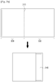
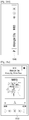
- the display 230 may consist of a first area 320 and a second area 330 which is larger than the first area 320 with reference to a folding line 310.
- the display 230 may include an exposure area 340 which is the exposed a part of the second area 330.
- FIG. 3C is a view illustrating a cover which is on the rear side of the user terminal device 200 when the user terminal device 200 is folded.
- the rear side of the user terminal device 200 may include a first cover 350 corresponding to the first area 320 and a second cover 360 corresponding to the second area 330.
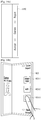
- the length of the folding line 310 is in parallel with a short side, but this is only an example.
- the length of the folding line 310 may be in parallel with a long side.
- the display 230 may consist of a first area 370 and a second area 380 with reference to the folding line 310.
- the display 230 may include an exposure area 390 of the second area 380, which is exposed to outside.
- the folding line 310 may be a line generated by a physical hinge.
- the folding line 310 may be a line which can be folded by a user.
- the communicator 240 performs communication with various types of external apparatuses according to various types of communication methods.
- the communicator 240 may include a WiFi chip 241, a Bluetooth chip 242, a wireless communication chip 243, and a Near Field Communication (NFC) chip 244.
- the controller 290 performs communication with various external apparatuses using the communicator 240.
- the WiFi chip 241 and the Bluetooth chip 242 perform communication according to a WiFi method and a Bluetooth method, respectively.
- various connection information such as an SSID and a session key may be transmitted/received first for communication connection and then, various information may be transmitted/received.
- the wireless communication chip 243 represents a chip which performs communication according to various communication standards such as IEEE, Zigbee, 3rd Generation (3G), 3rd Generation Partnership Project (3GPP), Long Term Evolution (LTE) and so on.
- the NFC chip 244 represents a chip which operates according to an NFC method which uses 13.56MHz band among various RF-ID frequency bands such as 135kHz, 13.56MHz, 433MHz, 860 ⁇ 960MHz, 2.45GHz, and so on.
- the storage 250 may store various programs and data necessary to operate the user terminal device 200. Specifically, the storage 250 may store programs and data to configure various screens to be displayed on a main area and a sub area.
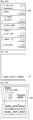
- FIG. 4 is a view provided to explain the structure of software stored in the user terminal device 200. According to FIG. 4 , the storage 250 may store an Operating System (OS) 410, a kernel 420, middleware 430, an application 440, etc.
- OS Operating System
- middleware middleware
- application 440 etc.
- the OS 410 controls and manages overall operations of hardware. In other words, the OS 410 manages hardware and is responsible for basic functions such as memory and security.
- the kernel 420 serves as a path transmitting various signals detected at the display 230, such as a touch signal, to the middleware 430.
- the middleware 430 includes various software modules for controlling the operation of the user terminal device 200.
- the middleware 430 includes an X11 module 430-1, an APP manager 430-2, a connection manager 430-3, a security module 430-4, a system manager 430-5, a multimedia framework 430-6, a UI framework 430-7, a window manager 430-8, and a writing recognition module 430-9.
- the X11 module 430-1 receives various event signals from various hardware provided in the user terminal device 200.
- the event may vary, ranging from an event of setting of a system alarm, an event of executing or terminating a specific program, etc.
- the APP manager 430-2 manages the execution state of various applications 440 which are installed in the storage 250.
- the APP manager 430-2 calls and executes an application corresponding to the event.
- connection manager 430-3 supports wired or wireless network connection.
- the connection manager 430-3 may include various detailed modules such as a DNET module, a UPnP module, etc.
- the security module 430-4 supports certification, permission, secure storage, etc., with respect to hardware.
- the system manager 430-5 monitors the state of each element of the user terminal device 200, and provides the monitoring result to other modules. For example, if there is not enough battery left, an error occurs, or connection is cut off, the system manager 430-5 may provide the monitoring result to a main UI framework 430-7 or a sub UI framework 430-9 and output an alarm message or an alarm sound.
- the multimedia framework 430-6 may be stored in the user terminal device 200, or may reproduce multimedia content provided from an external source.
- the multimedia framework 430-6 may include a player module, a camcorder module, a sound processing module, etc. Accordingly, the multimedia framework 430-6 may reproduce various multimedia content, and generate and reproduce screens and sounds.
- the main UI framework 430-7 provides various UIs to be displayed on a main area of the display 230
- the sub UI framework 430-9 provides various UIs to be displayed on a sub area.
- the main UI framework 430-7 and the sub UI framework 430-9 may include an image composite module to configure various objects, a coordinates composite module to calculate a coordinates where an object is to be displayed, a rendering module to render the configured object on the calculated coordinates, a 2D/3D UI toolkit to provide a tool for configuring a UI in 2D or 3D form, etc.
- the main UI framework 430-7 and the sub UI framework 430-9 may include an image composite module to configure various objects, a coordinates composite module to calculate a coordinates where an object is to be displayed, a rendering module to render the configured object on the calculated coordinates, a 2D/3D UI toolkit to provide a tool for configuring a UI in 2D or 3D form, etc.
- the window manager 430-8 may detect a touch event using a user's body part or pen or other input events. When such an event is detected, the window manager 430-8 transmits an event signal to the main UI framework 430-7 or the sub UI framework 430-9 so that an operation corresponding to the event is performed.
- various program modules such as a writing module for drawing a line according to a drag trace and an angle calculation module for calculating a pitch angle, a roll angle, a yaw angle, etc. based on a sensor value sensed by a movement detector 282 may be stored.
- the application module 440 includes applications 440-1 ⁇ 440-n for supporting various functions.
- program modules for providing various services such as a navigation program module, a game module, an electronic book module, a calendar module, an alarm management module, a music module, an electronic banking module, a stock module, a calculator module, an electronic mail module, a spreadsheet module, a word processor module, etc. may be included.
- Such applications may be set as default or may be set temporarily by a user when necessary. If an object is selected, the main CPU 294 may execute an application corresponding to the selected object using the application module 440.
- the storage 250 may additionally provide various programs such as a sensing module for analyzing signals sensed by various sensors, a messaging module including a messenger program, a Short Message Service (SMS) & Multimedia Message Service (MMS) program, an e-mail program, etc., a call info aggregator program module, a VoIP module, a web browser module, etc.
- a sensing module for analyzing signals sensed by various sensors
- MMS Short Message Service
- MMS Multimedia Message Service
- the audio processor 260 processes audio data of image content.
- the audio processor 260 may perform various processing such as decoding, amplification, noise filtering, compression, equalization, noise cancellation, echo or reverb removal or addition, etc. with respect to audio data.
- the audio data processed by the audio processor 260 may be output to the audio output unit 270 (e.g., audio outputter).
- the audio output unit 270 outputs not only various audio data which is processed in many ways such as decoding, amplification, and noise filtering by the audio processor 260 but also various alarm sounds or voice messages.
- the audio output unit 270 may be realized as a speaker, but this is only an example.
- the audio output unit 270 may be realized as an output terminal which may output audio data.
- the detector 280 detects various user interactions.
- the detector 280 may include a touch detector 281, a movement detector 282, and a folding detector 283, as illustrated in FIG. 2 .
- the touch detector 281 may detect a user's touch interaction using a touch panel attached to the rear side of a display panel.
- the movement detector 282 may detect a movement (for example, a rotation movement, a vertical movement, a horizontal movement, etc.) of the user terminal device 100 using at least one of an accelerator sensor, a geomagnetic sensor, and a gyro sensor.
- the folding detector 283 may detect at least one of whether the user terminal device 200 is folded with reference to the folding line 310 and the angle at which the terminal device 200 is folded using a bending sensor (for example, a light sensor, a fiber optic sensor, a conductive ink-based sensor, a conductive fabric sensor, etc.).
- the touch detector 281 might activate only a touch sensor disposed on the exposure area while the display 230 is folded, and inactivate a touch sensor disposed on the other areas.
- the controller 290 controls overall operations of the user terminal device 200 using various programs stored in the storage 250.
- the controller 290 includes a RAM 291, a ROM 292, a graphic processor 293, a main CPU 294, a first to an nth interface 295-1 ⁇ 295-n, and a bus 296.
- the RAM 291, the ROM 292, the graphic processor 293, the main CPU 294, the first to the nth interface 295-1 ⁇ 295-n, etc. may be interconnected through the bus 296.
- the ROM 292 stores a set of commands for system booting. If a turn-on command is input and thus, power is supplied, the main CPU 294 copies O/S stored in the storage 250 in the RAM 291 according to a command stored in the ROM 292, and boots a system by executing the O/S. When the booting is completed, the main CPU 294 copies various application programs stored in the storage 250 to the RAM 291, and executes the application programs copied in the RAM 291 to perform various operations.
- the graphic processor 293 generates a screen including various objects such as an icon, an image, a text, etc. using a computing unit (e.g., computer) and a rendering unit (e.g., renderer).
- the computing unit computes property values such as coordinates, shape, size, and color of each object to be displayed according to the layout of the screen using a control command received from the detector 280.
- the rendering unit generates a screen with various layouts including objects based on the property values computed by the computing unit.
- the screen generated by the rendering unit is displayed in a display area of the display 230.
- the main CPU 294 accesses the storage 250, and performs booting using the O/S stored in the storage 250.
- the main CPU 294 performs various operations using various programs, content, data, etc. stored in the storage 250.
- the first to the nth interface 295-1 ⁇ 295-n are connected to the above-described various elements.
- One of the above interface may be a network interface which is connected to an external apparatus via network.
- controller 290 may provide various functions using an exposure area which is exposed to the outside when the display 110 is folded.
- the controller 290 may control the display 230 to display a predetermined UI on the exposure area 340 of the second area 320, which is exposed to the outside.
- the predetermined UI may include at least one of a UI including the state information of the user terminal device 200 and a UI for controlling the user terminal device 200.
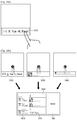
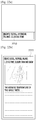
- the controller 290 may control the display 230 to display a UI 510 providing a memo function on the exposure area as illustrated in FIG. 5A .
- the controller 290 may control the display 230 to display an image according to the user input.
- the controller 290 may control the display 230 to display a UI for controlling a specific application on the exposure area. Specifically, if a folding interaction of folding the display 230 with reference to the folding line 310 such that the first area 320 and the second area 330 come in contact with each other is detected while a specific application is executed, the controller 290 may control the display 230 to display a UI for controlling the specific application on the exposure area. For example, as shown in FIG.
- the controller 290 may control the display 230 to display a UI 520 for controlling the music application on the exposure area.
- the UI 520 for controlling a music application may include information regarding currently-played music, a play/stop icon, a skip icon, a rewind icon, a next song, a past song, thumbs up, thumbs down, etc.
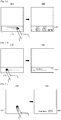
- the controller 290 may control the display 230 to display a UI including a hot key icon for checking the current state of the user terminal device 200 on the exposure area. For example, if a predetermined user interaction (for example, an interaction of touching or tapping the exposure area twice in a row) is detected while the display 230 is folded, the controller 290 may control the display 230 to display a UI 530 including a hot key icon for checking the current state of the user terminal device 200 on the exposure area as illustrated in FIG. 5C .
- the hot key icon for checking the current state of the user terminal device 200 may include a hot key icon for checking a battery state, a hot key icon for checking a network state, a hot key icon for checking display brightness setting, etc.
- the controller 290 may control the display 230 to display a UI informing that a message or data is received from the outside on the exposure area. For example, if a social network message (SNS) message is received from the outside through the communicator 240 while the display 230 is folded, the controller 290 may control the display 230 to display a UI 540 informing that the SNS message is received on the exposure area as illustrated in FIG. 5D .
- the UI 540 informing that an SNS message is received may include at least one of information regarding a sender and information regarding the SNS message.
- controller 290 may control the display 230 to display various types of UIs for releasing a lock state of the user terminal device 200 on the exposure area.
- the controller 290 may control the display 230 to display a UI 610 for inputting a pin number to release the lock state of the user terminal device 200 on the exposure area.
- the UI 610 for inputting a pin number may change the pin number by a touch interaction of swiping up and down. If a predetermined pin number is input on the UI 610 displayed on the exposure area, the controller 290 may release the lock state of the user terminal device 200. Additionally, the user may set the pin number through user input.
- the controller 290 may control the display 230 to display a UI 620 including a plurality of dots on a corner of the exposure area to release the lock state of the user terminal device 200 on the exposure area. In this case, if a touch interaction of connecting dots in a predetermined pattern is detected on the UI 620, the controller 290 may release the lock state of the user terminal device 200. Additionally, the user may set the pattern through user input.
- the controller 290 may control the display 230 to display a UI 630 in the form of a keyboard, e.g., a piano, to release the lock state of the user terminal device 200 on the exposure area.
- a touch interaction of touching the keyboard in a predetermined rhythm is detected on the UI 630, the controller may release the lock state of the user terminal device 200.
- the user may set the rhythm through user input.
- the controller 290 may control the display 230 to display a UI 640 including a home icon to release the lock state of the user terminal device on the exposure area. In this case, if a touch interaction of pinching out with reference to the home icon included in the UI 640 is detected, the controller 290 may release the lock state of the user terminal device 200.
- the controller 290 may control the display 230 to display a UI for changing the setting of the user terminal device 200 illustrated in FIG. 2 on the exposure area.
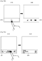
- the controller 290 may control the display 230 to display a UI 710 in the form of an arc for adjusting the volume of the user terminal device 200.
- the UI displayed on the exposure area adjusts the volume, but this is only an example.
- a UI for adjusting another setting of the user terminal device 200 (for example, display brightness, etc.) may be displayed.
- the controller 290 may control the display 230 to display a UI 730 for turning off the power of the user terminal device 200 at the corner area corresponding to the vertex where the touch interaction is detected.
- the controller 290 may control the display 230 to display a screen corresponding to the touched icon on full screen.
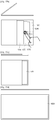
- the display 230 displays first to fourth icons 810 to 840 while the display 230 is folded. If an unfolding interaction of unfolding the display 230 is detected while the fourth icon 840 out of the first to the fourth icon 810 to 840 is touched, the controller 290 may control the display 230 to display a message window 850 corresponding to the fourth icon 840, as illustrated in FIG. 8B .
- an unfolding interaction is detected while the fourth icon 840 is touched, but this is only an example. If an unfolding interaction is detected while another icon is touched, a screen corresponding to the other-touched icon may be displayed on the full screen of the display 230. For example, if an unfolding interaction is detected while the first icon 810 is touched, the controller 290 may control the display 230 to display a full screen execution screen of a call application corresponding to the first icon 810 (for example, a recent call list screen, an address book screen, a call sending screen, etc.).
- a call application for example, a recent call list screen, an address book screen, a call sending screen, etc.
- the controller 290 may control the display 230 to display a web browser screen corresponding to the second icon 820 on full screen. If an unfolding interaction is detected while the third icon 830 is touched, the controller 290 may control the display 230 to display a full screen execution screen of a music application corresponding to the third icon 830 (for example, a music play screen, a music list screen, etc.).
- a music application for example, a music play screen, a music list screen, etc.
- the controller 290 may control the display 230 to display a screen for executing a specific function.
- the controller 290 may control the display 230 to display a UI 910 informing that a call request is received on the exposure area, as illustrated in FIG. 9A . If an unfolding interaction of unfolding a hinge angle of the display 230 as much as a predetermined angle (for example, 70° to 120°) is detected while the UI 910 informing that a call request is received is touched, the controller 290 may accept the call request, execute a speaker phone function, and control the display 230 to display an execution screen 920 including various icons as illustrated in FIG. 9B .
- a predetermined angle for example, 70° to 120°
- the controller 290 may control the display 230 to display a UI 1020 informing that the message is received along with the news information 1010 on the exposure area as illustrated in FIG. 10A . If an unfolding interaction of unfolding a hinge angle of the display 230 as much as a predetermined angle (for example, 70° to 120°) is detected while the UI 1020 informing that a message is received is touched, the controller 290 may control the display 230 to display a message window 1030 for writing a reply to the received message as illustrated in FIG. 10B .
- a predetermined angle for example, 70° to 120°
- controller 290 may control the display 230 to display different screens when the exposure area is touched and then, an unfolding interaction is detected and when an unfolding interaction is detected.
- the controller 290 may control the display 230 to display a UI 1110 corresponding to a music application on the exposure area as illustrated in FIG. 11A .
- the controller 290 may control the display 230 to display a UI 1120 informing that the message is received along with the music application UI 1110 on the exposure area as illustrated in FIG. 11B .
- the controller 290 may control the display 230 to display an execution screen 1130 of the existing music application as illustrated in FIG. 11C .
- a UI 1135 informing that a message is received may be displayed on one area of the execution screen 1130 of the music application for a predetermined time.
- the controller 290 may control the display 230 to display a message window 1140 for writing a reply to the received message as illustrated in FIG. 11D .
- controller 290 may control the display 230 to display different screens in the order of detecting an unfolding interaction and a touch interaction for lock-releasing.
- the controller 290 may release the lock state of the user terminal device 200, and as illustrated in the right side of FIG. 12A , may control the display 230 to display a first home screen 1220 including time information on the exposure area.
- the controller 290 may release the lock state of the user terminal device 200, and as illustrated in the right side of FIG. 12B , may control the display 230 to display a second home screen 1230 on full screen.
- the controller 290 may control the display 230 to display a UI 1240 for releasing the lock of the user terminal device on full screen as illustrated in the right side of FIG. 12C . If a touch interaction for lock-releasing is detected on the UI 1240 for releasing the lock of the user terminal device 200, which is displayed on full screen, the controller 290 may release the lock state of the user terminal device 200, and as illustrated in the right side of FIG. 12B , may control the display 230 to display the second home screen 1230 on full screen.
- controller 290 may control the display 230 to display a distinctive screen which is displayed only when an unfolding interaction is detected while a UI corresponding to a specific application is displayed on the exposure area and a screen which is displayed when an unfolding interaction is detected after the exposure area is touched.
- the controller 290 may control the display 230 to display a UI 1310 informing a call request is received on the exposure area as illustrated in the left side of FIG. 13A . If the UI 1310 displayed on the exposure area is touched and then, an unfolding interaction of unfolding the display 230 is detected, the controller 290 may control the display 230 to display an execution screen 1320 of a calendar application which is related to a call request function on full screen, as illustrated in the lower left side of FIG. 13A . Other applications, such as a memo application may display execution screens in response to the UI 1310 displayed on the exposure area being touched and then, an unfolding interaction of unfolding the display 230 being detected.
- the controller 290 may control the display 230 to display a call screen 1330 on full screen as illustrated in the lower right side of FIG. 13A .
- the controller 290 may control the display 230 to display a UI 1340 for controlling the music application on the exposure area as illustrated in the upper portion of FIG. 13B . If the UI 1340 displayed on the exposure area is touched and then an unfolding interaction of unfolding the display 230 is detected, the controller 290 may control the display 230 to maintain music play and display a play list 1350 on full screen as illustrated in the lower left side of FIG. 13B .
- the controller 290 may control the display 230 to display a music player screen 1360 on full screen as illustrated in the lower right side of FIG. 13B .
- the controller 290 may control the display 230 to display at least one icon for executing a specific function. If a second unfolding interaction of unfolding the display 230 completely while at least one icon is touched, the controller 290 may execute a function corresponding to the touched icon.
- the controller 290 may control the display 230 to display a UI 1410 informing that a call request is received on the exposure area as illustrated in FIG. 14A .
- the controller 290 may control the display 230 to display a UI 1420 including a plurality of icons 1430-1 to 1430-3 for performing various functions in relation with making a call as illustrated in FIG. 14B .
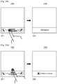
- the controller 290 may accept a call request, and as illustrated in FIG. 14C , may control the display 230 to display a call screen 1440 on the upper area and a list 1450 for selecting a photo to be shared. In this case, if a touch interaction of dragging one of a plurality of photos included in the list 1450 to the call screen 1440 is selected, the controller 290 may control the communicator 240 to transmit the photo where the touch interaction is detected to a receiver.
- the controller 290 may control the display 230 to display a plurality of guidance messages according to a hinge angle of the display 230 while the unfolding interaction is detected.
- the guidance messages may include a guidance message for informing an incoming text message, a guidance message for indicating a missed call, a guidance message for informing an incoming an SNS message, a guidance message for informing of application updates, etc.
- the controller 290 may control the display 230 to display one guidance message 1510 while the display 230 is folded. Subsequently, if an unfolding interaction of unfolding the display 230 is detected, the controller 290 may control the display 230 to display a different number of guidance messages according to a hinge angle of the display 230. For example, if a hinge angle of the display 230 is within a first angle range (for example, between 5° and 15°), the controller 290 may control the display 230 to display two guidance messages 1510, 1520.
- a first angle range for example, between 5° and 15°
- the controller 290 may control the display 230 to display three guidance messages 1510, 1520, 1530. That is, the controller 290 may increase the number of guidance messages displayed as a hinge angle of display 230 becomes greater.
- the controller 290 may control the display 230 to display five guidance messages (possibly overlapping) 1510 to 1550, as illustrated in FIG. 15B .
- the first guidance message 1510 which is updated most recently may be disposed on the top.
- the controller 290 may control the display 230 to display the second guidance message 1520 on the exposure area as illustrated in FIG. 15C .
- the controller 290 may control the display 230 to display a screen corresponding to the second guidance message 1520 on full screen as illustrated in FIG. 15D .
- controller 290 may perform different functions according to the direction of a touch interaction which is detected on the exposure area while the display 230 is folded.
- the controller 290 may control the display 230 to display a UI 1610 informing that the message is received on the exposure area as illustrated in FIG. 16A .
- the controller 290 may control the display 230 to display a UI informing the previous message or the next message on the exposure area according to the touch interaction.
- the controller 290 may delete a currently-received message.
- the controller 290 may store the received messages. Specifically, as illustrated in FIG. 16B , if a touch interaction in the up direction is detected on a UI 1620 informing that a first message is received, a touch interaction in the up direction is detected on a UI 1630 informing a second message is received, a touch interaction in the up direction is detected on a UI 1640 informing that a third message is received and then, an unfolding interaction of unfolding the display 230 is detected, the controller 290 may control the display 230 to display a screen 1620' including the first message, a screen 1630' including the second message, a screen 1640' including the third message and a home screen 1650.
- the controller 290 may maintain the current function even if the shape of the display 230 changes according to a folding interaction or an unfolding interaction, and control the display 230 to display a screen corresponding to the current function.
- the controller 290 may control the display 230 to display a UI 1710 corresponding to the music application on the exposure area as illustrated in FIG. 17A . If a call request is received while the UI 1710 corresponding to the music application is displayed on the exposure area, the controller 290 may control the display 230 to display a UI 1720 informing that a call request is received on the exposure area as illustrated in FIG. 17B .
- the controller 290 may control the display 230 to display a call screen 1730 on full screen as illustrated in FIG. 17C . Subsequently, when the telephone call is completed, the controller 290 may control the display 230 to display an execution screen 1740 of the music application on full screen as illustrated in FIG. 17D . If a folding interaction of folding the display 230 is detected again, the controller 290 may control the display 230 to display the UI 1710 corresponding to the music application on the exposure area as illustrated in FIG. 17E .
- the controller 290 may control the display 230 to display an execution screen 1810 of a music application on full screen while the music application is executed. If a call request is received from outside, the controller 290 may control the display 230 to display a screen 1820 for confirming whether to accept the call request as illustrated in FIG. 18B . If a folding interaction of folding the display 230 is detected while the screen 1820 for confirming whether to accept the call request is displayed, the controller 290 may control the display 230 to display a UI 1830 informing that a call request is rejected on the exposure area as illustrated in FIG. 18C .
- the controller 290 may control the display 230 to display a UI 1840 corresponding to the music application on the exposure area as illustrated in FIG. 18D . Subsequently, if an unfolding interaction of unfolding the display 230 is detected again, the controller 290 may control the display 230 to display the execution screen 1810 of the music application on full screen as illustrated in FIG. 18E .
- the controller 290 may determine a display area which can be watched by a user according to a hinge angle of the display 230, and control the display 230 to display a screen including different amount of information on the determined display area.
- the hinge angle of the display 230 may be matched with the watchable display area and then stored.
- the controller 290 may control the display 230 to display a first telephone call screen 1910 on full screen as illustrated in FIG. 19A .
- the controller 290 may determine a display area corresponding to the hinge angle, and as illustrated in FIG. 19B , may control the display 230 to display a second telephone call screen 1920 on the determined display area.
- the second telephone call screen 1920 may include less information and fewer icons than those included in the first telephone call screen 1910.
- the controller 290 may control the display 230 to display a UI 1930 informing that a telephone call is being performed on the exposure area as illustrated in FIG. 19C .
- the controller 290 may control the display 230 to display a first navigation screen 2010 on full screen as illustrated in FIG. 20A .
- the controller 290 may determine a display area corresponding to the hinge angle, and as illustrated in FIG. 20B , may control the display 230 to display a second navigation screen 2020 on the determined display area.
- the area guided by the second navigation screen 2020 may be smaller than the area guided by the first navigation screen 2010.
- the controller 290 may control the display 230 to display a third navigation screen 2030 on the exposure area as illustrated in FIG. 20C .
- the third navigation screen 2030 may include only direction information and distance information instead of a map screen included in the first navigation screen 2010 and the second navigation screen 2020.
- a map screen may also be included on the exposure area in third navigation screen 2030.
- the controller 290 may control the display 230 to reconfigure and display information such that the information corresponds to the size and direction of a screen.
- the controller 290 may control the display 230 to display a second address book list 2120 on the exposure area as illustrated in FIG. 21B .
- the first address book list 2110 might include user information such as image, name, telephone number, direct call icon, etc.
- the second address book list 2120 might include user information such as image and name only, but the display is not limited thereto.
- the controller 290 may control the display 230 to display a full screen 2220 including not only the news title but also the news image and the news text as illustrated in FIG. 22B .
- the controller 290 may control the display 230 to display different information on the exposure area and the hidden area when the display 230 is folded.
- the controller 290 may control the display 230 to display common information on an exposure area 2310 and private information on a hidden area 2320.
- the controller 290 may control the display 230 to display barcode information which is common information on the exposure area 2330, and credit card list and transaction information which is private information on the hidden area 2340.
- the detector 280 may detect a first user interaction of moving along a long side of the exposed area or a second user interaction of moving along a short side of the exposed area. If the first user interaction is detected through the detector 280, the controller 290 may control the display 230 to display an execution screen of an application which provides a first function on the exposure area. On the other hand, if the second user interaction is detected through the detector 280, the controller 290 may control the display 230 to display an execution screen of an application which provides a second function on the exposure area.
- the first user interaction of moving along a long side of the exposed area may include, for example, the first user interaction of moving in a direction in parallel with a long side of the exposed area.
- the second user interaction of moving along a short side of the exposed area may include, for example, the second user interaction of moving at right angles to the direction in parallel with a short side of the exposed area.
- being in parallel may include, for example, a state where a prolonged line of the long side of the exposed area and a prolonged line of a trace of the first user interaction which moves in a horizontal direction do not meet with each other or meet in an area outside the exposed area.
- being in parallel may include, for example, a state where a prolonged line of the short side of the exposed area and a prolonged line of a trace of the second user interaction which moves in a vertical direction do not meet with each other or meet in an area outside the exposed area.
- the first user interaction moving in one direction and the second user interaction moving at right angles to the one direction may include a case where a cross angle between a prolonged line of a trace of the first user interaction and a prolonged line of a trace of the second user interaction is either 90° or almost 90°.
- a cross angle between the prolonged lines is a value between 80° and 100°, it can be seen that the motion direction of the first user interaction is at right angles to the motion direction of the second user interaction.
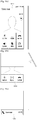
- FIGS. 24A to 24D are views illustrating an exemplary embodiment of performing various functions of the user terminal device 200 illustrated in FIG. 2 according to a user interaction on an exposure area.
- the detector 280 may detect a user interaction of moving in one direction (for example, in a right direction) along a long side 2411 of the exposure area.
- the state where an image is not displayed on the exposure area may include, for example, a state where the display 230 is inactive. If the detector 280 detects the user interaction, as illustrated in 2420 of FIG. 24A , the controller 290 may control the display 230 to display an execution screen 2421 of an application for displaying a home screen on the exposure area.
- the home screen 2421 may include, for example, the current time information or a timeline.
- the detector 280 may detect a user interaction of moving in an opposite direction to the one direction (for example, in a left direction) along the long side 2411 of the exposure area. If the detector 280 detects the user interaction, as illustrated in 2440 of FIG. 24B , the controller 290 may control the display 230 to display an execution screen 2441 of an application for displaying public information (for example, the number of unread messages, message sender information, etc.) on the exposure area.
- public information for example, the number of unread messages, message sender information, etc.
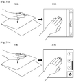
- the detector 280 may detect a user interaction of moving in one direction (for example, in an upward direction, a folding line direction, or a direction of a covered area) along a short side of the exposure area. If the detector 280 detects the user interaction, as illustrated in 2460 of FIG. 24C , the controller 290 may control the display 230 to display an execution screen 2461 of an application for displaying glanceable information on the exposure area.
- the glanceable information may be information that a user may check quickly (for example, within 1-2 seconds), and may include information such as the current time, the current weather, etc. When a predetermined time elapses after the glanceable information is displayed, the controller 290 may control the display 230 to not display an image.
- the detector 280 may detect a user interaction of moving in one direction (for example, in a downward direction, and a direction outside the display 230) along a short side 2412 of the exposure area. If the detector 280 detects the user interaction, as illustrated in 2480 of 24D, the controller 290 may control the display 230 to display an execution screen 2481 of an application for displaying state information of the user terminal device 200 (for example, volume information, networking information, battery information) on the exposure area. Alternatively, the controller 290 may control the display 230 to display a screen providing a UI for environment setting of the user terminal device 200 on the exposure area.
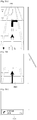
- FIGS. 25A to 25D are views provided to explain an exemplary embodiment of performing various functions of the user terminal device 200 illustrated in FIG. 2 according to a user interaction on the exposure area.
- the detector 280 may detect a user interaction of moving in one direction (for example, in a right direction) along a long side of the exposure area. If the detector 280 detects the user interaction, as illustrated in 2520 of FIG. 25A , the controller 290 may accept the telephone call request, and control the display 230 to display an execution screen 2521 of the telephone application indicating that the telephone call request has been accepted on the exposure area.
- the execution screen 2521 of the telephone application for accepting a telephone call request may include, for example, at least one of a telephone call acceptance icon and a telephone call time.
- the detector 280 may detect a user interaction of moving in one direction (for example, in a left direction) along a long side of the exposure area. If the detector 280 detects the user interaction, as illustrated in 2540 of FIG. 25B , the controller 290 may refuse the telephone call request, and may control the display 230 to display an execution screen 2541 of a telephone application indicating that the telephone call request has been refused on the exposure area.
- the execution screen 2541 of the telephone application for refusing a telephone call request may include, for example, at least one of a telephone call refusal phrase and a telephone call refusal icon.
- the detector 280 may detect a user interaction of moving in one direction (for example, in an upward direction) along a short side of the exposure area. If the detector 280 detects the user interaction, as illustrated in 2560 of FIG. 25C , the controller 290 may control the display 230 to display an execution screen 2561 of a telephone application indicating that a counterpart telephone number is stored in a contact list on the exposure area.
- the controller 290 may control the display 230 to display an execution screen of a telephone application including various functions such as the function of managing counterpart telephone numbers using a contact list.
- the detector 280 may detect a user interaction of moving in one direction (for example, in an upward direction) along a short side of the exposure area.
- the controller 290 may control the display 230 to display the execution screen 2561 of the telephone application indicating that a counterpart telephone number is stored in a contact list on the exposure area.
- the detector 280 may detect a user interaction of moving in one direction (for example, in a downward direction) along a short side of the exposure area. If the detector 280 detects the user interaction, as illustrated in 2580 of FIG. 25D , the controller 290 may control the display 230 to display an execution screen 2581 of a telephone application indicating that a telephone number of the counterpart who requests a telephone call is stored in a spam list on the exposure area. In addition, the controller 290 may control the display 230 to display an execution screen of a telephone application indicating that a counterpart telephone number is deleted from a telephone history list on the exposure area.
- the detector 280 may detect a user interaction of moving in one direction (for example, in a downward direction) along a short side of the exposure area.
- the controller 290 may control the display 230 to display the execution screen 2581 of the telephone application indicating that a counterpart telephone number is stored in a spam list on the exposure area.
- FIGS. 26A to 26D illustrate an exemplary embodiment of performing various functions of the user terminal device 200 illustrated in FIG. 2 according to a user interaction on the exposure area.
- the detector 280 may detect a user interaction of moving in one direction (for example, in a right direction) along a long side of the exposure area. If the detector 280 detects the user interaction, as illustrated in 2620 of FIG. 26A , the controller 290 may control the display 230 to display an execution screen 2621 of the message application for displaying a previously received message.
- the detector 280 may detect a user interaction of moving in one direction (for example, in a left direction) along a long side of the exposure area. If the detector 280 detects the user interaction, as illustrated in 2640 of FIG. 26B , the controller 290 may control the display 230 to display an execution screen 2641 of a message application for displaying a message after the message.
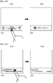
- the detector 280 may detect a user interaction of moving in one direction (for example, in a upward direction) along a short side of the exposure area. If the detector 280 detects the user interaction, as illustrated in 2660 of FIG. 26C , the controller 290 controls the display 230 to display an execution screen 2661 of an application indicating that the received message is stored.
- the detector 280 may detect a user interaction of moving in one direction (for example, in a downward direction) along a short side of the exposure area. If the detector 280 detects the user interaction, as illustrated in 2680 of FIG. 26D , the controller 290 may control the display 230 to display an execution screen 2681 of an application indicating that the received message is deleted.
- the controller 290 may provide different functions of an application according to the type of a detected user interaction.
- the controller 290 may perform functions related to storage, such as keeping, scrapping, and reminding of the displayed image information.
- the controller 290 may perform the function of deleting the displayed image information. If the detector 280 detects a user interaction of moving in one direction (for example, in a left or right direction) along a long side of the exposure area, the controller 290 may perform the feature of displaying other information related to the displayed image information.
- the controller 290 may control the display 230 to display an upper menu or a lower menu of the execution screen of the displayed application on the exposure area.
- the controller 290 may control the display 230 to display an execution screen of an application providing a specialized function (for example, storing or deleting a telephone number) on the execution screen of the application.
- the controller 290 may control the display 230 to immediately display an execution screen of an application providing the function of controlling information in the execution screen.
- the controller 290 may control the display 230 to display a home screen the size of the exposure area, a notice, and an execution screen of an application provided by a third party.
- the controller 290 may provide a function that replaces a hard key, or may control the display 230 to display an execution screen of an application providing a quick setting menu.
- FIGS. 27A to 27C are views illustrating an exemplary embodiment of performing various functions of the user terminal device 200 illustrated in FIG. 2 according to a user interaction on the exposure area.
- the controller 290 may control the display 230 to display an execution screen 2711 of a music player application for displaying information on music which is currently reproduced (for example, the name of the music or singer information) on the exposure area.
- the controller 290 may control the display 230 to display a graphic which shows that a Long Playing Record (LPR) is inserted between the first display area and the second display area and part of the LPR is exposed on the exposure area.
- the detector 280 may detect a user interaction of touching the exposed area.
- LPR Long Playing Record
- the controller 290 may control the display 230 to display an execution screen 2721 of a music player application for displaying a menu to control music which is currently reproduced on the exposure area.
- the menu to control music may include, for example, a UI for pausing currently-reproduced music, a UI for searching a playlist where the currently-reproduced music is included or searching music which comes next to the currently-reproduced music from a music album, and a UI for searching music before the currently-reproduced music from a playlist where the currently-reproduced music is included.
- the detector 280 may detect a user interaction of touching the UI for pausing the currently-reproduced music.
- the controller 290 may pause the currently-reproduced music, and control the display 230 to display an execution screen 2731 of a music player application for displaying a menu to control the paused music. While the menu to control the paused music is displayed, the detector 280 may detect a user interaction of touching the UI for searching music which comes next to the currently-paused music from a playlist or a music album where the currently-paused music is included.
- the controller 290 may search music which comes next to the currently-paused music from a playlist or a music album, and control the display 230 to display an execution screen 2741 of a music player application for displaying information regarding the music which comes next to the currently-paused music.
- the execution screen 2741 of the music player application may also display a menu to control the music which comes next. While the menu to control the music which comes next is displayed, the detector 280 may detect a user interaction of touching a UI for reproducing the next music.
- the controller 290 may reproduce the next music. Subsequently, after a predetermined time elapses, the controller 290 may control the display 230 to not display the menu to control the next music.
- the detector 280 may detect a user interaction of moving in one direction (for example, in a left direction) along a long side of the exposure area. If the detector 280 detects the user interaction, as illustrated in 2770 of FIG. 27B , the controller 290 may reproduce music which comes after the currently-reproduced music in a playlist or a music album where the currently-reproduced music is included, and control the display 230 to display an execution screen 2771 of a music player application for displaying information regarding the currently-reproduced music (that is, the next music).
- the detector 280 may detect a user interaction of moving in one direction (for example, in a right direction) along a long side of the exposure area.
- the controller 290 may reproduce music before the currently-reproduced music in a playlist or a music album where the currently-reproduced music is included, and control the display 230 to display an execution screen of a music player application for displaying information regarding the currently-reproduced music (that is, the previous music).
- the detector 280 may detect a user interaction of moving in one direction (for example, in a downward direction) along a short side of the exposure area. If the detector 280 detects the user interaction, as illustrated in 2790 of FIG. 27C , the controller 290 may control the display 230 to display an execution screen 2791 of a music player application for displaying information regarding a playlist or a music album including the currently-reproduced music (for example, the name of the playlist or the music album).
- the controller 290 may control the display 230 to display a graphic which shows part of the LPR inserted between the first display area and the second display area is extracted on the exposure area.
- the detector 280 may detect a user interaction of moving in one direction (for example, in a left direction) along a long side of the exposure area. If the detector 280 detects the user interaction, as illustrated in 2795 of FIG. 27C , the controller 290 may control the display 230 to display an execution screen 2796 of a music player application for displaying information related to the playlist or music album which comes next in the folder including the currently-reproduced playlist or music album on the exposure area.
- the detector 280 may detect a user interaction of moving in one direction (for example, in an upward direction) along a short side of the exposure area. If the detector 280 detects the user interaction, as illustrated in 2798 of FIG. 27C , the controller 290 may control the display 230 to display a graphic which shows that part of the extracted LPR is inserted between the first display area and the second display area on the exposure area. Subsequently, the controller 290 may reproduce music included in the next playlist or music album, and control the display 230 to display an execution screen 2799 of a music player application for displaying information regarding the currently-reproduced music.
- FIG. 28 is a view illustrating an exemplary embodiment of performing various functions of the user terminal device 200 illustrated in FIG. 2 according to a user interaction of tilting the user terminal device 200.
- the controller 290 may control the display 230 to display an execution screen 2811 of an application where a graphic showing that a message is popping out of a pocket when the message is received is displayed on the exposure area.
- the detector 280 may detect a user interaction of tilting the user terminal device 200 towards the direction of the exposure area. If the detector 280 detects the user interaction, as illustrated in 2820 of FIG. 28C , the controller 290 may control the display 230 to display an execution screen 2821 of an application where the content of a message is displayed on the exposure area.
- the detector 280 may detect a user interaction of tilting the user terminal device 200 in an opposite direction to the exposure area. If the detector 280 detects the user interaction, as illustrated in 2840 of FIG. 28 , the controller 290 may store a message in the storage 250, and control the display 230 to display an execution screen 2841 of an application for displaying a graphic showing that a message is inserted and kept in a pocket on the exposure area.
- FIG. 29 is a view illustrating an exemplary embodiment of performing various functions of the user terminal device 200 illustrated in FIG. 2 according to a user interaction on a side of the user terminal device 200.
- the controller 290 may control the display 230 to display an execution screen 2911 of an application for displaying a graphic showing that part of a content (for example, a message) is protruded between the first and the second display areas when the message is received on the exposure area.
- the detector 280 may detect a user interaction of tapping one side of the user terminal device 200.
- the detector 280 may detect a user interaction of tapping a hinge unit, a folding line or around the folding line of the display 230. If the detector 280 detects the user interaction, as illustrated in 2920 of FIG.
- the controller 290 may control the display 230 to display an execution screen 2921 of an application for displaying a graphic showing that most of the content is protruded between the first and the second display areas on the exposure area so that the content can be identified. While the graphic showing that most of the content is protruded between the first and the second display areas is displayed on the exposure area, the detector 280 may detect a user interaction of tapping another side of the user terminal device 200. For example, the detector 280 may detect a user interaction of tapping a bezel on the exposure area or a corner of the exposure area. If the detector 280 detects the user interaction, as illustrated in 2930 of FIG.
- the controller 290 may control the display 230 to display an execution screen 2931 of an application for displaying a graphic showing that part of a content is protruded between the first and the second display areas on the exposure area.
- the controller 290 may control the display 230 to not display the content on the exposure area.
- FIG. 30 is a view illustrating an exemplary embodiment of performing various functions of the user terminal device 200 illustrated in FIG. 2 according to a user interaction on the exposure area.
- the controller 290 may control the display 230 to display an execution screen 3011 of an application for displaying a graphic showing that a zipper is locked to indicate that the exposed screen is in a lock state on the exposure area.
- the detector 280 may detect a user interaction of moving in one direction (for example, in a downward direction) along a long side of the exposure area. If the detector 280 detects the user interaction, as illustrated in 3020 of FIG. 30 , the controller 290 may display at least one content (for example, public information) by releasing the lock state of the exposed screen, and control the display 230 to display an execution screen 3021 of an application for displaying a graphic showing that the zipper is opened on the exposure area.
- content for example, public information
- FIGS. 31A and 31B are views illustrating an exemplary embodiment of performing various functions of the user terminal device 200 illustrated in FIG. 2 according to a user interaction on a cover of the user terminal device 200.
- the detector 280 may detect a user interaction of pressing a cover of the user terminal device 200.
- the exposure area may not display any image, or may display an image in a lock state.
- the controller 290 may control the display 230 to display part of an application which is currently used. While the part of the application is displayed, the detector 280 may detect a user interaction of stopping the operation of pressing the cover of the user terminal device 200. If the detector 280 detects the user interaction, the controller 290 may control the display 230 to not display the part of the application on the exposed screen.
- the detector 280 may detect a user interaction of pressing the cover of the user terminal device 200.
- the exposure area may not display any image, or may display an image in a lock state.
- the controller 290 may control the display 230 to display a preview screen of an application which is currently used.
- the application is a music application
- the preview screen of the application may be a menu to control the music which is currently reproduced.
- the detector 280 may detect a user interaction of stopping the operation of pressing the cover of the user terminal device 200. If the detector 280 detects the user interaction, the controller 290 may control the display 230 to not display the preview screen of the application on the exposed screen.
- FIG. 32 is a flowchart illustrating a displaying method of the user terminal device 200 according to another exemplary embodiment.
- the display 230 may be folded forward such that a first area faces a second area with reference to a folding line, and a part of the second area may be exposed to outside (S3210).
- the user terminal device 200 may receive a user interaction on the exposure area (S3220).
- the user terminal device 200 may determine whether the received user interaction is a first user interaction of moving along a long side of the exposure area, a second user interaction of moving along a short side of the exposure area, or a third user interaction of touching the exposure area (S3230).
- the user terminal device 200 may display an execution screen of an application providing a first function on the exposure area (S3240).
- the user terminal device 200 may display an execution screen of an application providing a second function on the exposure area (S3250).
- the user terminal device 200 may display an execution screen of an application providing a third function on the exposure area (S3260).
- the display 230 displays a UI on the exposure area which is an exposed area when the display 230 is folded and thus, a user may perform various functions of the user terminal device through the UI displayed on the exposure area, even when the display is folded, and the displayed UI may provide various information.
- the displaying method of a user terminal device may be realized as a program and provided in the user terminal device.
- a non-transitory computer readable medium including a program of a control method of the user terminal device is stored may be provided.
- the non-transitory recordable medium refers to a medium which may store data semi-permanently and a memory, and may be readable by an apparatus.
- the non-transitory readable medium may be CD, DVD, hard disk, Blu-ray disk, USB, memory card, ROM, etc.
Claims (6)
- Procédé d'affichage d'un dispositif terminal d'utilisateur comprenant un seul écran flexible partagé en une première zone et une deuxième zone par une charnière, et une zone d'exposition de la première zone non couverte par la deuxième zone quand le dispositif terminal d'utilisateur est replié de sorte que la première zone fait face à la deuxième zone, un message reçu de l'extérieur étant affiché sur la zone d'exposition, ledit procédé comprenant :la détection d'une première interaction d'utilisateur ou d'une deuxième interaction d'utilisateur différente de la première interaction d'utilisateur sur la zone d'exposition, le terminal d'utilisateur étant replié le long de la charnière de sorte que la première zone fait face à la deuxième zone ; etl'affichage d'un premier écran d'exécution de fonction sur la zone d'exposition en réaction à la détection de la première interaction d'utilisateur sur la zone d'exposition, et l'affichage d'un deuxième écran d'exécution de fonction sur la zone d'exposition en réaction à la détection de la deuxième interaction d'utilisateur sur la zone d'exposition,la première zone étant continue,la première interaction d'utilisateur comprenant un déplacement dans une première direction sur la longueur de la zone d'exposition et un déplacement dans une deuxième direction opposée à la première direction sur la longueur de la zone d'exposition, et la deuxième interaction d'utilisateur comprenant un déplacement sur la largeur de la zone d'exposition,l'affichage du premier écran d'exécution de fonction de l'application fournissant la première fonction sur la zone d'exposition comprenant :l'affichage d'un troisième écran d'exécution de fonction sur la zone d'exposition en réaction à la détection d'un déplacement dans la première direction, et l'affichage d'un quatrième écran d'exécution de fonction sur la zone d'exposition en réaction à la détection d'un déplacement dans la deuxième direction,le premier écran d'exécution de fonction étant un écran d'exécution d'application de messagerie pour la délivrance d'un message suivant ou d'un message précédent ou d'une indication que le message est mémorisé ou d'une indication que le message est supprimé, etle deuxième écran d'exécution de fonction étant un autre écran d'exécution d'application de messagerie pour la délivrance d'un autre message suivant ou d'un autre message précédent ou d'une autre indication que le message est mémorisé ou d'une autre indication que le message est supprimé.
- Procédé selon la revendication 1,
où la première interaction d'utilisateur est l'interaction d'utilisateur de déplacement dans une première direction parallèlement à la longueur de la zone d'exposition, et
où la deuxième interaction d'utilisateur est l'interaction d'utilisateur de déplacement perpendiculaire à la première direction parallèlement à la largeur de la zone d'exposition. - Procédé selon la revendication 1,
où la deuxième interaction d'utilisateur comprend un déplacement dans une troisième direction sur la largeur de la zone d'exposition et un déplacement dans une quatrième direction opposée à la troisième direction sur la largeur de la zone d'exposition, et
où l'affichage du deuxième écran d'exécution de fonction sur la zone d'exposition comprend :
l'affichage d'un cinquième écran d'exécution de fonction sur la zone d'exposition en réaction à la détection d'un déplacement dans la troisième direction,
et l'affichage d'un sixième écran d'exécution de fonction sur la zone d'exposition en réaction à la détection d'un déplacement dans la quatrième direction. - Procédé selon la revendication 1, comprenant en outre :la détection d'une troisième interaction d'utilisateur de contact tactile sur la zone d'exposition ; etl'affichage d'un troisième écran d'exécution de fonction sur la zone d'exposition en réaction à la détection de la troisième interaction d'utilisateur.
- Dispositif terminal d'utilisateur, ledit dispositif comprenant :un écran partagé par une charnière en une première zone et une deuxième zone, et une zone d'exposition de la première zone non couverte par la deuxième zone quand le dispositif terminal d'utilisateur est remplié de sorte que la première zone fait face à la deuxième zone, un message reçu de l'extérieur étant affiché sur la zone d'exposition ;un détecteur prévu pour détecter une première interaction d'utilisateur ou une deuxième interaction d'utilisateur différente de la première interaction d'utilisateur sur la zone d'exposition, le dispositif terminal d'utilisateur étant replié sur la charnière de sorte que la première zone fait face à la deuxième zone ; etun contrôleur prévu pour afficher un premier écran d'exécution de fonction sur la zone d'exposition en réaction à la détection de la première interaction d'utilisateur sur la zone d'exposition, et pour afficher un deuxième écran d'exécution de fonction sur la zone d'exposition en réaction à la détection de la deuxième interaction d'utilisateur sur la zone d'exposition,la première zone étant continue,la première interaction d'utilisateur comprenant un déplacement dans une première direction sur la longueur de la zone d'exposition et un déplacement dans une deuxième direction opposée à la première direction sur la longueur de la zone d'exposition, et la deuxième interaction d'utilisateur comprenant un déplacement sur la largeur de la zone d'exposition,le contrôleur étant prévu pour commander l'affichage par l'écran d'un troisième écran d'exécution de fonction sur la zone d'exposition en réaction à la détection de déplacement dans la première direction, et commander l'affichage par l'écran d'un quatrième écran d'exécution de fonction sur la zone d'exposition en réaction à la détection de déplacement dans la deuxième direction,le premier écran d'exécution de fonction étant un écran d'exécution d'application de messagerie pour la délivrance d'un message suivant ou d'un message précédent ou d'une indication que le message est mémorisé ou d'une indication que le message est supprimé, etle deuxième écran d'exécution de fonction étant un autre écran d'exécution d'application de messagerie pour la délivrance d'un autre message suivant ou d'un autre message précédent ou d'une autre indication que le message est mémorisé ou d'une autre indication que le message est supprimé.
- Dispositif selon la revendication 5,
où la première interaction d'utilisateur est l'interaction d'utilisateur de déplacement dans une première direction parallèlement à la longueur de la zone d'exposition, et
où la deuxième interaction d'utilisateur est l'interaction d'utilisateur de déplacement perpendiculaire à la première direction parallèlement à la largeur de la zone d'exposition.
Applications Claiming Priority (3)
| Application Number | Priority Date | Filing Date | Title |
|---|---|---|---|
| US201461937744P | 2014-02-10 | 2014-02-10 | |
| KR1020140083282A KR102377785B1 (ko) | 2014-02-10 | 2014-07-03 | 사용자 단말 장치 및 이의 디스플레이 방법 |
| PCT/KR2015/001341 WO2015119482A1 (fr) | 2014-02-10 | 2015-02-10 | Terminal utilisateur et procédé d'affichage associé |
Publications (3)
| Publication Number | Publication Date |
|---|---|
| EP3105666A1 EP3105666A1 (fr) | 2016-12-21 |
| EP3105666A4 EP3105666A4 (fr) | 2017-10-04 |
| EP3105666B1 true EP3105666B1 (fr) | 2020-04-22 |
Family
ID=53774919
Family Applications (1)
| Application Number | Title | Priority Date | Filing Date |
|---|---|---|---|
| EP15746532.9A Active EP3105666B1 (fr) | 2014-02-10 | 2015-02-10 | Terminal utilisateur et procédé d'affichage associé |
Country Status (4)
| Country | Link |
|---|---|
| US (1) | US10067641B2 (fr) |
| EP (1) | EP3105666B1 (fr) |
| CN (1) | CN105980954B (fr) |
| WO (1) | WO2015119482A1 (fr) |
Families Citing this family (18)
| Publication number | Priority date | Publication date | Assignee | Title |
|---|---|---|---|---|
| KR102331956B1 (ko) | 2014-02-10 | 2021-11-29 | 삼성전자주식회사 | 사용자 단말 장치 및 이의 디스플레이 방법 |
| KR102561200B1 (ko) | 2014-02-10 | 2023-07-28 | 삼성전자주식회사 | 사용자 단말 장치 및 이의 디스플레이 방법 |
| KR102119843B1 (ko) | 2014-02-10 | 2020-06-05 | 삼성전자주식회사 | 사용자 단말 장치 및 이의 디스플레이 방법 |
| KR102131018B1 (ko) | 2014-06-20 | 2020-07-07 | 삼성전자 주식회사 | 수신 메시지 처리 방법 및 이를 구현하는 전자 장치 |
| US10306057B1 (en) * | 2016-01-07 | 2019-05-28 | William Sasso | Automatic call blocking and routing system and method |
| US10248224B2 (en) * | 2016-10-25 | 2019-04-02 | Microsoft Technology Licensing, Llc | Input based on interactions with a physical hinge |
| CN106936982A (zh) * | 2017-01-14 | 2017-07-07 | 惠州Tcl移动通信有限公司 | 具有柔性显示屏的终端及其显示方法 |
| JP7170413B2 (ja) * | 2017-04-26 | 2022-11-14 | エヌエイチエヌ コーポレーション | 受信メッセージ表示方法、メッセージアプリケーションプログラム、およびモバイル端末機 |
| CN107256149B (zh) * | 2017-05-26 | 2021-03-30 | 北京小米移动软件有限公司 | 用户界面的更新方法和装置 |
| KR102440291B1 (ko) * | 2017-11-15 | 2022-09-07 | 삼성디스플레이 주식회사 | 전자장치 및 전자장치 제어방법 |
| KR102255469B1 (ko) * | 2018-03-06 | 2021-05-24 | 삼성전자주식회사 | 플렉서블한 디스플레이를 포함하는 전자 장치 및 그 동작 방법 |
| US10877781B2 (en) * | 2018-07-25 | 2020-12-29 | Sony Corporation | Information processing apparatus and information processing method |
| CN109525710B (zh) * | 2018-10-22 | 2021-06-22 | 维沃移动通信有限公司 | 一种访问应用程序的方法和装置 |
| CN110673697B (zh) * | 2019-09-23 | 2021-08-27 | Oppo广东移动通信有限公司 | 电子设备的控制方法、装置、电子设备及存储介质 |
| USD973679S1 (en) * | 2019-10-28 | 2022-12-27 | Samsung Electronics Co., Ltd. | Display screen or portion thereof with transitional graphical user interface |
| USD949187S1 (en) * | 2020-01-07 | 2022-04-19 | Samsung Electronics Co., Ltd. | Display screen or portion thereof with graphical user interface |
| WO2022049795A1 (fr) * | 2020-09-07 | 2022-03-10 | 株式会社Nttドコモ | Dispositif de traitement d'informations |
| WO2022119137A1 (fr) | 2020-12-03 | 2022-06-09 | 삼성전자 주식회사 | Dispositif électronique comprenant un dispositif d'affichage extensible et procédé pour fournir du contenu au dispositif électronique |
Citations (4)
| Publication number | Priority date | Publication date | Assignee | Title |
|---|---|---|---|---|
| US20090164951A1 (en) * | 2007-12-19 | 2009-06-25 | Nvidia Corporation | Input architecture for devices with small input areas and executing multiple applications |
| US20100162169A1 (en) * | 2008-12-23 | 2010-06-24 | Nokia Corporation | Method, Apparatus and Computer Program Product for Providing a Dynamic Slider Interface |
| US20130076649A1 (en) * | 2011-09-27 | 2013-03-28 | Scott A. Myers | Electronic Devices With Sidewall Displays |
| US20130300697A1 (en) * | 2012-05-14 | 2013-11-14 | Samsung Electronics Co. Ltd. | Method and apparatus for operating functions of portable terminal having bended display |
Family Cites Families (52)
| Publication number | Priority date | Publication date | Assignee | Title |
|---|---|---|---|---|
| EP1168143A1 (fr) * | 2000-06-27 | 2002-01-02 | Koninklijke Philips Electronics N.V. | Dispositif portable à processeur comportant une pluralité de modules d'écran dont au moins un module d'écran repliable sur un module d'écran principal |
| JP4019179B2 (ja) | 2003-11-19 | 2007-12-12 | 富士フイルム株式会社 | 電子機器 |
| ATE431038T1 (de) | 2003-11-21 | 2009-05-15 | Nokia Corp | Zweischritt-aktivierung eines telefons |
| JP4189928B2 (ja) | 2005-02-18 | 2008-12-03 | ソニー・エリクソン・モバイルコミュニケーションズ株式会社 | 携帯型電子装置、携帯型電子装置の機能制御方法及びプログラム |
| WO2007105369A1 (fr) | 2006-03-10 | 2007-09-20 | Nec Corporation | Telephone mobile |
| US7787917B2 (en) | 2006-12-28 | 2010-08-31 | Intel Corporation | Folding electronic device with continuous display |
| US9423995B2 (en) | 2007-05-23 | 2016-08-23 | Google Technology Holdings LLC | Method and apparatus for re-sizing an active area of a flexible display |
| JP2009124449A (ja) | 2007-11-14 | 2009-06-04 | Ntt Docomo Inc | 移動体端末装置及びその操作方法 |
| KR101387527B1 (ko) * | 2007-12-06 | 2014-04-23 | 엘지전자 주식회사 | 단말기 및 그 메뉴 아이콘 디스플레이 방법 |
| US8851992B2 (en) * | 2008-08-29 | 2014-10-07 | Disney Enterprises, Inc. | Music player for video game consoles and electronic devices operable in sleep or power-saving modes |
| US8866840B2 (en) | 2008-09-08 | 2014-10-21 | Qualcomm Incorporated | Sending a parameter based on screen size or screen resolution of a multi-panel electronic device to a server |
| US8836611B2 (en) | 2008-09-08 | 2014-09-16 | Qualcomm Incorporated | Multi-panel device with configurable interface |
| US8860632B2 (en) | 2008-09-08 | 2014-10-14 | Qualcomm Incorporated | Multi-panel device with configurable interface |
| US8803816B2 (en) * | 2008-09-08 | 2014-08-12 | Qualcomm Incorporated | Multi-fold mobile device with configurable interface |
| US8863038B2 (en) | 2008-09-08 | 2014-10-14 | Qualcomm Incorporated | Multi-panel electronic device |
| JP2010066918A (ja) | 2008-09-09 | 2010-03-25 | Nec Personal Products Co Ltd | 情報処理装置および表示制御方法 |
| KR101521219B1 (ko) | 2008-11-10 | 2015-05-18 | 엘지전자 주식회사 | 플렉서블 디스플레이를 이용하는 휴대 단말기 및 그 제어방법 |
| KR101517082B1 (ko) * | 2008-11-10 | 2015-04-30 | 엘지전자 주식회사 | 플렉서블 디스플레이를 이용하는 휴대 단말기 및 그 제어방법 |
| KR101569776B1 (ko) | 2009-01-09 | 2015-11-19 | 삼성전자주식회사 | 접히는 표시부를 가지는 휴대 단말기 및 이의 운용 방법 |
| KR101063882B1 (ko) | 2009-03-13 | 2011-09-15 | 한국과학기술원 | 폴딩형 다기능 디스플레이 장치 |
| US10013135B2 (en) | 2009-03-20 | 2018-07-03 | Microsoft Technology Licensing, Llc | Adjustable user interfaces with movable separators |
| JP2009201157A (ja) | 2009-06-08 | 2009-09-03 | Nec Corp | 折り畳み式携帯端末 |
| JP5212344B2 (ja) | 2009-12-08 | 2013-06-19 | 富士通モバイルコミュニケーションズ株式会社 | 携帯通信機器 |
| US20110241998A1 (en) | 2010-03-30 | 2011-10-06 | Mckinney Susan | Flexible portable communication device |
| US8462106B2 (en) | 2010-11-09 | 2013-06-11 | Research In Motion Limited | Image magnification based on display flexing |
| KR101841570B1 (ko) | 2010-11-18 | 2018-03-26 | 삼성전자 주식회사 | 듀얼디스플레이 접이식단말기 |
| KR101781852B1 (ko) * | 2011-01-04 | 2017-09-26 | 엘지전자 주식회사 | 이동단말기 및 그 제어방법 |
| JP2014511524A (ja) | 2011-02-10 | 2014-05-15 | サムスン エレクトロニクス カンパニー リミテッド | タッチスクリーンディスプレイを設ける携帯機器及びその制御方法 |
| TWI438740B (zh) | 2011-04-13 | 2014-05-21 | Wistron Corp | 可撓式電子裝置 |
| KR101801359B1 (ko) | 2011-07-28 | 2017-11-24 | 엘지전자 주식회사 | 이동 단말기 |
| KR101881865B1 (ko) * | 2011-08-30 | 2018-07-25 | 삼성전자주식회사 | 휴대단말기의 사용자 인터페이스 변경장치 및 방법 |
| JP2013073352A (ja) | 2011-09-27 | 2013-04-22 | Nec Casio Mobile Communications Ltd | 携帯型電子機器、入力操作受付方法およびプログラム |
| EP2581808B1 (fr) | 2011-10-14 | 2019-04-10 | BlackBerry Limited | Procédé et système pour contrôler un procédé avec mouvements de pliage |
| KR101828306B1 (ko) * | 2011-10-18 | 2018-02-13 | 삼성전자 주식회사 | 휴대 단말기의 운영 방법 및 장치 |
| JP2013105310A (ja) | 2011-11-14 | 2013-05-30 | Sony Corp | 情報処理装置、制御方法およびプログラム |
| KR20130056674A (ko) * | 2011-11-22 | 2013-05-30 | 삼성전자주식회사 | 플렉시블 디스플레이 장치 및 이를 이용한 유저 인터페이스 표시 방법 |
| JP2013117885A (ja) | 2011-12-02 | 2013-06-13 | Nintendo Co Ltd | 情報処理プログラム、情報処理装置、情報処理システム及び情報処理方法 |
| KR20130069066A (ko) | 2011-12-16 | 2013-06-26 | 삼성전자주식회사 | 디스플레이 장치 및 그 디스플레이 방법 |
| KR20130080937A (ko) | 2012-01-06 | 2013-07-16 | 삼성전자주식회사 | 플랙서블 디스플레이를 구비하는 단말장치의 화면 표시장치 및 방법 |
| EP2811384A4 (fr) | 2012-02-03 | 2015-09-23 | Nec Corp | Dispositif terminal, procédé de traitement et programme associé |
| US8837126B2 (en) | 2012-02-28 | 2014-09-16 | Lg Electronics Inc. | Display device |
| KR101661526B1 (ko) | 2012-04-08 | 2016-10-04 | 삼성전자주식회사 | 플렉서블 디스플레이 장치 및 그 ui 방법 |
| KR101721046B1 (ko) * | 2012-04-08 | 2017-03-29 | 삼성전자주식회사 | 디스플레이 장치 및 그에 대한 제어 방법 |
| KR102013587B1 (ko) | 2012-05-03 | 2019-08-23 | 엘지전자 주식회사 | 이동 단말기 및 그것의 제어방법 |
| KR101425443B1 (ko) | 2012-05-09 | 2014-08-04 | 엘지전자 주식회사 | 파우치 및 이에 수납되는 휴대 전자기기 |
| KR101871716B1 (ko) | 2012-05-14 | 2018-06-27 | 엘지전자 주식회사 | 플렉서블 디스플레이를 구비하는 이동단말기 및 그 제어방법 |
| KR101958802B1 (ko) | 2012-07-26 | 2019-03-18 | 삼성디스플레이 주식회사 | 접이식 표시 장치 |
| KR101916416B1 (ko) | 2012-07-30 | 2018-11-08 | 삼성전자주식회사 | 플렉서블 디스플레이 장치 및 그 디스플레이 방법 |
| KR102016119B1 (ko) * | 2012-08-01 | 2019-08-30 | 삼성전자주식회사 | 플렉서블 디스플레이 장치 및 그 제어 방법 |
| KR102080741B1 (ko) | 2012-08-29 | 2020-02-24 | 엘지전자 주식회사 | 이동 단말기 및 그것의 제어방법 |
| US9524030B2 (en) * | 2013-04-26 | 2016-12-20 | Immersion Corporation | Haptic feedback for interactions with foldable-bendable displays |
| KR102256677B1 (ko) * | 2013-12-02 | 2021-05-28 | 삼성디스플레이 주식회사 | 플렉서블 표시장치 및 이의 영상 표시방법 |
-
2015
- 2015-02-10 EP EP15746532.9A patent/EP3105666B1/fr active Active
- 2015-02-10 WO PCT/KR2015/001341 patent/WO2015119482A1/fr active Application Filing
- 2015-02-10 US US14/618,421 patent/US10067641B2/en active Active
- 2015-02-10 CN CN201580007989.1A patent/CN105980954B/zh active Active
Patent Citations (4)
| Publication number | Priority date | Publication date | Assignee | Title |
|---|---|---|---|---|
| US20090164951A1 (en) * | 2007-12-19 | 2009-06-25 | Nvidia Corporation | Input architecture for devices with small input areas and executing multiple applications |
| US20100162169A1 (en) * | 2008-12-23 | 2010-06-24 | Nokia Corporation | Method, Apparatus and Computer Program Product for Providing a Dynamic Slider Interface |
| US20130076649A1 (en) * | 2011-09-27 | 2013-03-28 | Scott A. Myers | Electronic Devices With Sidewall Displays |
| US20130300697A1 (en) * | 2012-05-14 | 2013-11-14 | Samsung Electronics Co. Ltd. | Method and apparatus for operating functions of portable terminal having bended display |
Non-Patent Citations (2)
| Title |
|---|
| AMARNATH NATARAJAN: "How To Answer A Call On Samsung Galaxy Note 2", 1 January 2013 (2013-01-01), XP055651506, Retrieved from the Internet <URL:https://www.primeinspiration.com/how-to-answer-a-call-on-samsung-galaxy-note-2.html> [retrieved on 20191210] * |
| ARTHUR BODOLEC ET AL: "UX Archive - Mailbox", 27 April 2013 (2013-04-27), XP055651298, Retrieved from the Internet <URL:https://web.archive.org/web/20130427055457/http://uxarchive.com/apps/mailbox> [retrieved on 20191210] * |
Also Published As
| Publication number | Publication date |
|---|---|
| CN105980954B (zh) | 2019-12-13 |
| EP3105666A1 (fr) | 2016-12-21 |
| EP3105666A4 (fr) | 2017-10-04 |
| CN105980954A (zh) | 2016-09-28 |
| US10067641B2 (en) | 2018-09-04 |
| US20150227249A1 (en) | 2015-08-13 |
| WO2015119482A1 (fr) | 2015-08-13 |
Similar Documents
| Publication | Publication Date | Title |
|---|---|---|
| US11347372B2 (en) | User terminal device and displaying method thereof | |
| US11789591B2 (en) | User terminal device and displaying method thereof | |
| EP3105666B1 (fr) | Terminal utilisateur et procédé d'affichage associé | |
| US11543940B2 (en) | User terminal device and displaying method thereof |
Legal Events
| Date | Code | Title | Description |
|---|---|---|---|
| PUAI | Public reference made under article 153(3) epc to a published international application that has entered the european phase |
Free format text: ORIGINAL CODE: 0009012 |
|
| STAA | Information on the status of an ep patent application or granted ep patent |
Free format text: STATUS: REQUEST FOR EXAMINATION WAS MADE |
|
| 17P | Request for examination filed |
Effective date: 20160712 |
|
| AK | Designated contracting states |
Kind code of ref document: A1 Designated state(s): AL AT BE BG CH CY CZ DE DK EE ES FI FR GB GR HR HU IE IS IT LI LT LU LV MC MK MT NL NO PL PT RO RS SE SI SK SM TR |
|
| AX | Request for extension of the european patent |
Extension state: BA ME |
|
| DAX | Request for extension of the european patent (deleted) | ||
| A4 | Supplementary search report drawn up and despatched |
Effective date: 20170904 |
|
| RIC1 | Information provided on ipc code assigned before grant |
Ipc: H04M 1/725 20060101ALI20170829BHEP Ipc: G06F 3/0482 20130101ALI20170829BHEP Ipc: G06F 3/0484 20130101ALI20170829BHEP Ipc: H04M 1/02 20060101ALI20170829BHEP Ipc: G06F 1/16 20060101ALI20170829BHEP Ipc: G06F 3/0487 20130101ALI20170829BHEP Ipc: G06F 9/44 20060101ALI20170829BHEP Ipc: G06F 3/0488 20130101AFI20170829BHEP |
|
| STAA | Information on the status of an ep patent application or granted ep patent |
Free format text: STATUS: EXAMINATION IS IN PROGRESS |
|
| 17Q | First examination report despatched |
Effective date: 20190212 |
|
| REG | Reference to a national code |
Ref country code: DE Ref legal event code: R079 Ref document number: 602015051164 Country of ref document: DE Free format text: PREVIOUS MAIN CLASS: G06F0003048000 Ipc: G06F0003048800 |
|
| GRAP | Despatch of communication of intention to grant a patent |
Free format text: ORIGINAL CODE: EPIDOSNIGR1 |
|
| STAA | Information on the status of an ep patent application or granted ep patent |
Free format text: STATUS: GRANT OF PATENT IS INTENDED |
|
| RIC1 | Information provided on ipc code assigned before grant |
Ipc: G06F 9/451 20180101ALI20191213BHEP Ipc: G06F 9/44 20180101ALI20191213BHEP Ipc: G06F 3/0487 20130101ALI20191213BHEP Ipc: G06F 3/0484 20130101ALI20191213BHEP Ipc: G06F 3/0488 20130101AFI20191213BHEP Ipc: G11B 27/34 20060101ALI20191213BHEP Ipc: G06F 3/0482 20130101ALI20191213BHEP Ipc: G06F 1/16 20060101ALI20191213BHEP Ipc: H04M 1/02 20060101ALI20191213BHEP Ipc: H04M 1/725 20060101ALI20191213BHEP |
|
| INTG | Intention to grant announced |
Effective date: 20200114 |
|
| GRAS | Grant fee paid |
Free format text: ORIGINAL CODE: EPIDOSNIGR3 |
|
| GRAA | (expected) grant |
Free format text: ORIGINAL CODE: 0009210 |
|
| STAA | Information on the status of an ep patent application or granted ep patent |
Free format text: STATUS: THE PATENT HAS BEEN GRANTED |
|
| AK | Designated contracting states |
Kind code of ref document: B1 Designated state(s): AL AT BE BG CH CY CZ DE DK EE ES FI FR GB GR HR HU IE IS IT LI LT LU LV MC MK MT NL NO PL PT RO RS SE SI SK SM TR |
|
| REG | Reference to a national code |
Ref country code: CH Ref legal event code: EP |
|
| REG | Reference to a national code |
Ref country code: IE Ref legal event code: FG4D |
|
| REG | Reference to a national code |
Ref country code: DE Ref legal event code: R096 Ref document number: 602015051164 Country of ref document: DE |
|
| REG | Reference to a national code |
Ref country code: AT Ref legal event code: REF Ref document number: 1260993 Country of ref document: AT Kind code of ref document: T Effective date: 20200515 |
|
| REG | Reference to a national code |
Ref country code: NL Ref legal event code: FP |
|
| REG | Reference to a national code |
Ref country code: LT Ref legal event code: MG4D |
|
| PG25 | Lapsed in a contracting state [announced via postgrant information from national office to epo] |
Ref country code: PT Free format text: LAPSE BECAUSE OF FAILURE TO SUBMIT A TRANSLATION OF THE DESCRIPTION OR TO PAY THE FEE WITHIN THE PRESCRIBED TIME-LIMIT Effective date: 20200824 Ref country code: LT Free format text: LAPSE BECAUSE OF FAILURE TO SUBMIT A TRANSLATION OF THE DESCRIPTION OR TO PAY THE FEE WITHIN THE PRESCRIBED TIME-LIMIT Effective date: 20200422 Ref country code: NO Free format text: LAPSE BECAUSE OF FAILURE TO SUBMIT A TRANSLATION OF THE DESCRIPTION OR TO PAY THE FEE WITHIN THE PRESCRIBED TIME-LIMIT Effective date: 20200722 Ref country code: IS Free format text: LAPSE BECAUSE OF FAILURE TO SUBMIT A TRANSLATION OF THE DESCRIPTION OR TO PAY THE FEE WITHIN THE PRESCRIBED TIME-LIMIT Effective date: 20200822 Ref country code: SE Free format text: LAPSE BECAUSE OF FAILURE TO SUBMIT A TRANSLATION OF THE DESCRIPTION OR TO PAY THE FEE WITHIN THE PRESCRIBED TIME-LIMIT Effective date: 20200422 Ref country code: FI Free format text: LAPSE BECAUSE OF FAILURE TO SUBMIT A TRANSLATION OF THE DESCRIPTION OR TO PAY THE FEE WITHIN THE PRESCRIBED TIME-LIMIT Effective date: 20200422 Ref country code: GR Free format text: LAPSE BECAUSE OF FAILURE TO SUBMIT A TRANSLATION OF THE DESCRIPTION OR TO PAY THE FEE WITHIN THE PRESCRIBED TIME-LIMIT Effective date: 20200723 |
|
| REG | Reference to a national code |
Ref country code: AT Ref legal event code: MK05 Ref document number: 1260993 Country of ref document: AT Kind code of ref document: T Effective date: 20200422 |
|
| PG25 | Lapsed in a contracting state [announced via postgrant information from national office to epo] |
Ref country code: RS Free format text: LAPSE BECAUSE OF FAILURE TO SUBMIT A TRANSLATION OF THE DESCRIPTION OR TO PAY THE FEE WITHIN THE PRESCRIBED TIME-LIMIT Effective date: 20200422 Ref country code: LV Free format text: LAPSE BECAUSE OF FAILURE TO SUBMIT A TRANSLATION OF THE DESCRIPTION OR TO PAY THE FEE WITHIN THE PRESCRIBED TIME-LIMIT Effective date: 20200422 Ref country code: HR Free format text: LAPSE BECAUSE OF FAILURE TO SUBMIT A TRANSLATION OF THE DESCRIPTION OR TO PAY THE FEE WITHIN THE PRESCRIBED TIME-LIMIT Effective date: 20200422 Ref country code: BG Free format text: LAPSE BECAUSE OF FAILURE TO SUBMIT A TRANSLATION OF THE DESCRIPTION OR TO PAY THE FEE WITHIN THE PRESCRIBED TIME-LIMIT Effective date: 20200722 |
|
| PG25 | Lapsed in a contracting state [announced via postgrant information from national office to epo] |
Ref country code: AL Free format text: LAPSE BECAUSE OF FAILURE TO SUBMIT A TRANSLATION OF THE DESCRIPTION OR TO PAY THE FEE WITHIN THE PRESCRIBED TIME-LIMIT Effective date: 20200422 |
|
| REG | Reference to a national code |
Ref country code: DE Ref legal event code: R097 Ref document number: 602015051164 Country of ref document: DE |
|
| PG25 | Lapsed in a contracting state [announced via postgrant information from national office to epo] |
Ref country code: RO Free format text: LAPSE BECAUSE OF FAILURE TO SUBMIT A TRANSLATION OF THE DESCRIPTION OR TO PAY THE FEE WITHIN THE PRESCRIBED TIME-LIMIT Effective date: 20200422 Ref country code: ES Free format text: LAPSE BECAUSE OF FAILURE TO SUBMIT A TRANSLATION OF THE DESCRIPTION OR TO PAY THE FEE WITHIN THE PRESCRIBED TIME-LIMIT Effective date: 20200422 Ref country code: IT Free format text: LAPSE BECAUSE OF FAILURE TO SUBMIT A TRANSLATION OF THE DESCRIPTION OR TO PAY THE FEE WITHIN THE PRESCRIBED TIME-LIMIT Effective date: 20200422 Ref country code: CZ Free format text: LAPSE BECAUSE OF FAILURE TO SUBMIT A TRANSLATION OF THE DESCRIPTION OR TO PAY THE FEE WITHIN THE PRESCRIBED TIME-LIMIT Effective date: 20200422 Ref country code: SM Free format text: LAPSE BECAUSE OF FAILURE TO SUBMIT A TRANSLATION OF THE DESCRIPTION OR TO PAY THE FEE WITHIN THE PRESCRIBED TIME-LIMIT Effective date: 20200422 Ref country code: EE Free format text: LAPSE BECAUSE OF FAILURE TO SUBMIT A TRANSLATION OF THE DESCRIPTION OR TO PAY THE FEE WITHIN THE PRESCRIBED TIME-LIMIT Effective date: 20200422 Ref country code: AT Free format text: LAPSE BECAUSE OF FAILURE TO SUBMIT A TRANSLATION OF THE DESCRIPTION OR TO PAY THE FEE WITHIN THE PRESCRIBED TIME-LIMIT Effective date: 20200422 Ref country code: DK Free format text: LAPSE BECAUSE OF FAILURE TO SUBMIT A TRANSLATION OF THE DESCRIPTION OR TO PAY THE FEE WITHIN THE PRESCRIBED TIME-LIMIT Effective date: 20200422 |
|
| PG25 | Lapsed in a contracting state [announced via postgrant information from national office to epo] |
Ref country code: SK Free format text: LAPSE BECAUSE OF FAILURE TO SUBMIT A TRANSLATION OF THE DESCRIPTION OR TO PAY THE FEE WITHIN THE PRESCRIBED TIME-LIMIT Effective date: 20200422 Ref country code: PL Free format text: LAPSE BECAUSE OF FAILURE TO SUBMIT A TRANSLATION OF THE DESCRIPTION OR TO PAY THE FEE WITHIN THE PRESCRIBED TIME-LIMIT Effective date: 20200422 |
|
| PLBE | No opposition filed within time limit |
Free format text: ORIGINAL CODE: 0009261 |
|
| STAA | Information on the status of an ep patent application or granted ep patent |
Free format text: STATUS: NO OPPOSITION FILED WITHIN TIME LIMIT |
|
| 26N | No opposition filed |
Effective date: 20210125 |
|
| PG25 | Lapsed in a contracting state [announced via postgrant information from national office to epo] |
Ref country code: SI Free format text: LAPSE BECAUSE OF FAILURE TO SUBMIT A TRANSLATION OF THE DESCRIPTION OR TO PAY THE FEE WITHIN THE PRESCRIBED TIME-LIMIT Effective date: 20200422 |
|
| PG25 | Lapsed in a contracting state [announced via postgrant information from national office to epo] |
Ref country code: MC Free format text: LAPSE BECAUSE OF FAILURE TO SUBMIT A TRANSLATION OF THE DESCRIPTION OR TO PAY THE FEE WITHIN THE PRESCRIBED TIME-LIMIT Effective date: 20200422 |
|
| REG | Reference to a national code |
Ref country code: BE Ref legal event code: MM Effective date: 20210228 |
|
| PG25 | Lapsed in a contracting state [announced via postgrant information from national office to epo] |
Ref country code: CH Free format text: LAPSE BECAUSE OF NON-PAYMENT OF DUE FEES Effective date: 20210228 Ref country code: LU Free format text: LAPSE BECAUSE OF NON-PAYMENT OF DUE FEES Effective date: 20210210 Ref country code: LI Free format text: LAPSE BECAUSE OF NON-PAYMENT OF DUE FEES Effective date: 20210228 |
|
| PG25 | Lapsed in a contracting state [announced via postgrant information from national office to epo] |
Ref country code: FR Free format text: LAPSE BECAUSE OF NON-PAYMENT OF DUE FEES Effective date: 20210228 Ref country code: IE Free format text: LAPSE BECAUSE OF NON-PAYMENT OF DUE FEES Effective date: 20210210 |
|
| PG25 | Lapsed in a contracting state [announced via postgrant information from national office to epo] |
Ref country code: BE Free format text: LAPSE BECAUSE OF NON-PAYMENT OF DUE FEES Effective date: 20210228 |
|
| PG25 | Lapsed in a contracting state [announced via postgrant information from national office to epo] |
Ref country code: HU Free format text: LAPSE BECAUSE OF FAILURE TO SUBMIT A TRANSLATION OF THE DESCRIPTION OR TO PAY THE FEE WITHIN THE PRESCRIBED TIME-LIMIT; INVALID AB INITIO Effective date: 20150210 |
|
| PGFP | Annual fee paid to national office [announced via postgrant information from national office to epo] |
Ref country code: GB Payment date: 20230119 Year of fee payment: 9 Ref country code: DE Payment date: 20230119 Year of fee payment: 9 |
|
| PG25 | Lapsed in a contracting state [announced via postgrant information from national office to epo] |
Ref country code: CY Free format text: LAPSE BECAUSE OF FAILURE TO SUBMIT A TRANSLATION OF THE DESCRIPTION OR TO PAY THE FEE WITHIN THE PRESCRIBED TIME-LIMIT Effective date: 20200422 |
|
| PGFP | Annual fee paid to national office [announced via postgrant information from national office to epo] |
Ref country code: NL Payment date: 20230120 Year of fee payment: 9 |