EP3105396B1 - Ensemble palier pour porte - Google Patents
Ensemble palier pour porte Download PDFInfo
- Publication number
- EP3105396B1 EP3105396B1 EP15704295.3A EP15704295A EP3105396B1 EP 3105396 B1 EP3105396 B1 EP 3105396B1 EP 15704295 A EP15704295 A EP 15704295A EP 3105396 B1 EP3105396 B1 EP 3105396B1
- Authority
- EP
- European Patent Office
- Prior art keywords
- damper
- bearing arrangement
- door
- bearing
- arrangement according
- Prior art date
- Legal status (The legal status is an assumption and is not a legal conclusion. Google has not performed a legal analysis and makes no representation as to the accuracy of the status listed.)
- Active
Links
- 238000013016 damping Methods 0.000 claims description 25
- 230000007246 mechanism Effects 0.000 claims description 8
- 230000006835 compression Effects 0.000 claims description 5
- 238000007906 compression Methods 0.000 claims description 5
- 230000008878 coupling Effects 0.000 description 3
- 238000010168 coupling process Methods 0.000 description 3
- 238000005859 coupling reaction Methods 0.000 description 3
- 210000003746 feather Anatomy 0.000 description 3
- 230000008901 benefit Effects 0.000 description 1
- 230000000903 blocking effect Effects 0.000 description 1
- 230000008859 change Effects 0.000 description 1
- 238000010276 construction Methods 0.000 description 1
- 238000009434 installation Methods 0.000 description 1
- 238000004519 manufacturing process Methods 0.000 description 1
- 238000000034 method Methods 0.000 description 1
- 230000008569 process Effects 0.000 description 1
- 238000009420 retrofitting Methods 0.000 description 1
Images


Classifications
-
- E—FIXED CONSTRUCTIONS
- E05—LOCKS; KEYS; WINDOW OR DOOR FITTINGS; SAFES
- E05F—DEVICES FOR MOVING WINGS INTO OPEN OR CLOSED POSITION; CHECKS FOR WINGS; WING FITTINGS NOT OTHERWISE PROVIDED FOR, CONCERNED WITH THE FUNCTIONING OF THE WING
- E05F1/00—Closers or openers for wings, not otherwise provided for in this subclass
- E05F1/08—Closers or openers for wings, not otherwise provided for in this subclass spring-actuated, e.g. for horizontally sliding wings
- E05F1/10—Closers or openers for wings, not otherwise provided for in this subclass spring-actuated, e.g. for horizontally sliding wings for swinging wings, e.g. counterbalance
- E05F1/12—Mechanisms in the shape of hinges or pivots, operated by springs
- E05F1/1246—Mechanisms in the shape of hinges or pivots, operated by springs with a coil spring perpendicular to the pivot axis
- E05F1/1253—Mechanisms in the shape of hinges or pivots, operated by springs with a coil spring perpendicular to the pivot axis with a compression spring
-
- E—FIXED CONSTRUCTIONS
- E05—LOCKS; KEYS; WINDOW OR DOOR FITTINGS; SAFES
- E05F—DEVICES FOR MOVING WINGS INTO OPEN OR CLOSED POSITION; CHECKS FOR WINGS; WING FITTINGS NOT OTHERWISE PROVIDED FOR, CONCERNED WITH THE FUNCTIONING OF THE WING
- E05F3/00—Closers or openers with braking devices, e.g. checks; Construction of pneumatic or liquid braking devices
- E05F3/04—Closers or openers with braking devices, e.g. checks; Construction of pneumatic or liquid braking devices with liquid piston brakes
- E05F3/10—Closers or openers with braking devices, e.g. checks; Construction of pneumatic or liquid braking devices with liquid piston brakes with a spring, other than a torsion spring, and a piston, the axes of which are the same or lie in the same direction
- E05F3/104—Closers or openers with braking devices, e.g. checks; Construction of pneumatic or liquid braking devices with liquid piston brakes with a spring, other than a torsion spring, and a piston, the axes of which are the same or lie in the same direction with cam-and-slide transmission between driving shaft and piston within the closer housing
-
- E—FIXED CONSTRUCTIONS
- E05—LOCKS; KEYS; WINDOW OR DOOR FITTINGS; SAFES
- E05F—DEVICES FOR MOVING WINGS INTO OPEN OR CLOSED POSITION; CHECKS FOR WINGS; WING FITTINGS NOT OTHERWISE PROVIDED FOR, CONCERNED WITH THE FUNCTIONING OF THE WING
- E05F3/00—Closers or openers with braking devices, e.g. checks; Construction of pneumatic or liquid braking devices
- E05F3/22—Additional arrangements for closers, e.g. for holding the wing in opened or other position
- E05F3/221—Mechanical power-locks, e.g. for holding the wing open or for free-moving zones
-
- E—FIXED CONSTRUCTIONS
- E05—LOCKS; KEYS; WINDOW OR DOOR FITTINGS; SAFES
- E05F—DEVICES FOR MOVING WINGS INTO OPEN OR CLOSED POSITION; CHECKS FOR WINGS; WING FITTINGS NOT OTHERWISE PROVIDED FOR, CONCERNED WITH THE FUNCTIONING OF THE WING
- E05F5/00—Braking devices, e.g. checks; Stops; Buffers
-
- E—FIXED CONSTRUCTIONS
- E05—LOCKS; KEYS; WINDOW OR DOOR FITTINGS; SAFES
- E05D—HINGES OR SUSPENSION DEVICES FOR DOORS, WINDOWS OR WINGS
- E05D7/00—Hinges or pivots of special construction
- E05D7/08—Hinges or pivots of special construction for use in suspensions comprising two spigots placed at opposite edges of the wing, especially at the top and the bottom, e.g. trunnions
- E05D7/081—Hinges or pivots of special construction for use in suspensions comprising two spigots placed at opposite edges of the wing, especially at the top and the bottom, e.g. trunnions the pivot axis of the wing being situated near one edge of the wing, especially at the top and bottom, e.g. trunnions
-
- E—FIXED CONSTRUCTIONS
- E05—LOCKS; KEYS; WINDOW OR DOOR FITTINGS; SAFES
- E05F—DEVICES FOR MOVING WINGS INTO OPEN OR CLOSED POSITION; CHECKS FOR WINGS; WING FITTINGS NOT OTHERWISE PROVIDED FOR, CONCERNED WITH THE FUNCTIONING OF THE WING
- E05F3/00—Closers or openers with braking devices, e.g. checks; Construction of pneumatic or liquid braking devices
- E05F3/22—Additional arrangements for closers, e.g. for holding the wing in opened or other position
-
- E—FIXED CONSTRUCTIONS
- E05—LOCKS; KEYS; WINDOW OR DOOR FITTINGS; SAFES
- E05Y—INDEXING SCHEME RELATING TO HINGES OR OTHER SUSPENSION DEVICES FOR DOORS, WINDOWS OR WINGS AND DEVICES FOR MOVING WINGS INTO OPEN OR CLOSED POSITION, CHECKS FOR WINGS AND WING FITTINGS NOT OTHERWISE PROVIDED FOR, CONCERNED WITH THE FUNCTIONING OF THE WING
- E05Y2201/00—Constructional elements; Accessories therefore
- E05Y2201/60—Suspension or transmission members; Accessories therefore
- E05Y2201/622—Suspension or transmission members elements
- E05Y2201/624—Arms
- E05Y2201/626—Levers
-
- E—FIXED CONSTRUCTIONS
- E05—LOCKS; KEYS; WINDOW OR DOOR FITTINGS; SAFES
- E05Y—INDEXING SCHEME RELATING TO HINGES OR OTHER SUSPENSION DEVICES FOR DOORS, WINDOWS OR WINGS AND DEVICES FOR MOVING WINGS INTO OPEN OR CLOSED POSITION, CHECKS FOR WINGS AND WING FITTINGS NOT OTHERWISE PROVIDED FOR, CONCERNED WITH THE FUNCTIONING OF THE WING
- E05Y2201/00—Constructional elements; Accessories therefore
- E05Y2201/60—Suspension or transmission members; Accessories therefore
- E05Y2201/622—Suspension or transmission members elements
- E05Y2201/628—Bearings
-
- E—FIXED CONSTRUCTIONS
- E05—LOCKS; KEYS; WINDOW OR DOOR FITTINGS; SAFES
- E05Y—INDEXING SCHEME RELATING TO HINGES OR OTHER SUSPENSION DEVICES FOR DOORS, WINDOWS OR WINGS AND DEVICES FOR MOVING WINGS INTO OPEN OR CLOSED POSITION, CHECKS FOR WINGS AND WING FITTINGS NOT OTHERWISE PROVIDED FOR, CONCERNED WITH THE FUNCTIONING OF THE WING
- E05Y2600/00—Mounting or coupling arrangements for elements provided for in this subclass
- E05Y2600/40—Mounting location; Visibility of the elements
- E05Y2600/41—Concealed
-
- E—FIXED CONSTRUCTIONS
- E05—LOCKS; KEYS; WINDOW OR DOOR FITTINGS; SAFES
- E05Y—INDEXING SCHEME RELATING TO HINGES OR OTHER SUSPENSION DEVICES FOR DOORS, WINDOWS OR WINGS AND DEVICES FOR MOVING WINGS INTO OPEN OR CLOSED POSITION, CHECKS FOR WINGS AND WING FITTINGS NOT OTHERWISE PROVIDED FOR, CONCERNED WITH THE FUNCTIONING OF THE WING
- E05Y2900/00—Application of doors, windows, wings or fittings thereof
- E05Y2900/10—Application of doors, windows, wings or fittings thereof for buildings or parts thereof
- E05Y2900/13—Application of doors, windows, wings or fittings thereof for buildings or parts thereof characterised by the type of wing
- E05Y2900/132—Doors
-
- E—FIXED CONSTRUCTIONS
- E05—LOCKS; KEYS; WINDOW OR DOOR FITTINGS; SAFES
- E05Y—INDEXING SCHEME RELATING TO HINGES OR OTHER SUSPENSION DEVICES FOR DOORS, WINDOWS OR WINGS AND DEVICES FOR MOVING WINGS INTO OPEN OR CLOSED POSITION, CHECKS FOR WINGS AND WING FITTINGS NOT OTHERWISE PROVIDED FOR, CONCERNED WITH THE FUNCTIONING OF THE WING
- E05Y2900/00—Application of doors, windows, wings or fittings thereof
- E05Y2900/30—Application of doors, windows, wings or fittings thereof for domestic appliances
- E05Y2900/31—Application of doors, windows, wings or fittings thereof for domestic appliances for refrigerators
Definitions
- the present invention relates to a bearing arrangement for a door, in particular for refrigerators, according to the preamble of claim 1.
- the DE 20 2006 010 482 U1 discloses an arrangement for pivotally mounting a door of a refrigerator or freezer.
- the pivotable door is coupled to a lever, via which a locking device and a damping device are actuated.
- the locking device and the damping device can be actuated via a pivotable component which is moved through the door over a certain pivoting range.
- the rigid coupling of the damping device with the locking device via the pivoting part has the disadvantage that the damping forces or closing forces cannot be flexibly adapted to the respective door. In addition, only comparatively low damping forces and closing forces can be brought about.
- the US 3,273,196 discloses a fitting for a swing door in which a closing spring and a damper device are arranged adjacent to a vertical axis.
- the shooting spring pretensions the door in the closing direction and acts on a curve guide connected to the axis.
- the damper device also acts on a cam with a cam.
- a first cam track movable through the bearing axis is provided for moving the locking device and a second cam track movable through the bearing axis for moving the damper.
- the curve guides can have corresponding control projections which act on the locking device and / or on the damper.
- Two separate cam guides can be used for the locking device and the damper, but it is also possible to provide a single cam guide which then acts on both the locking device and the damping.
- the first and the second cam track are preferably connected in a rotationally fixed manner to the bearing axis, so that a particularly compact construction is possible.
- the first and second cam guides can be arranged offset to one another in the axial direction or can be formed by a single disk on which control projections are formed.
- the second curve guide actuates the damper to damp the door both in the closing direction before reaching the closing position and in the opening direction before reaching the maximum opening position.
- a single damper can be used to provide closing damping and also opening damping.
- the damper is actuated by corresponding control projections on the second curve guide, the opening damping taking place before reaching the maximum opening position, which can be, for example, in a range between 90 ° and 180 °.
- the opening damping and the closing damping can extend over a pivoting range of the door of at least at least 5 °, preferably in the case of the shooting damping between 10 ° and 50 ° before the closing position and in the opening damping between 5 ° and 25 ° before the maximum opening position.
- the locking device and the damper are housed in a housing that can either be installed inside a refrigerator or outside.
- the damper is preferably designed as a linear pressure damper, which causes a higher damping force when compressed than when pulled apart.
- the damper can provide high braking forces when closing or opening damping, the damper is barely or not noticeable by the user when moving in the opposite direction.
- a pull or rotary damper can be used instead of a pressure damper.
- the damper is preferably rotatably mounted on the housing on one side and rotatably held on a swivel part on the opposite side.
- the second curve guide can have control projections which act on the swivel part and / or a roller arranged on the swivel part in order to actuate the damper when the door is moved.
- the closing device preferably has a compression spring which is clamped between two end pieces.
- One end piece is rotatably mounted on the housing and the opposite end piece on a rotatably mounted actuating part.
- the rotatably mounted actuating part can then be moved via at least one control projection on the first cam guide, wherein a rotatable roller on which the at least one control projection acts can also be provided on the actuating part.
- the actuating part for moving the locking device can be rotated independently of the pivoting part for actuating the damper, the pivoting part and actuating part preferably being rotatably mounted on the housing about the same axis.
- a latching mechanism is provided according to the invention in order to latch the locking device in a tensioned state when the door is open. This makes it possible to move the door in a freewheel after tensioning the locking device, without friction or braking forces acting through the locking device.
- the locking mechanism has a locking pawl which can be actuated by a control cam, the locking pawl being biased by a spring into the position releasing the locking. This prevents the pawl from accidentally blocking the door.
- the locking mechanism enables a compact structure, because the locking device is only moved over part of the door's deflection path, so that only for this range of movement does installation space have to be made available.
- the forces of the closing device and the damper act in a particularly advantageous manner in a plane substantially perpendicular to the axis of rotation of the bearing axis of the bearing arrangement.
- the bearing axis is preferably substantially vertical, while the forces of the damper and the closing device act essentially horizontally in the installed state. This results in a particularly flat design of the bearing arrangement.
- the bearing arrangement according to the invention can be used in particular for household appliances, for example for refrigerators or freezers. Of course, it can also be used for furniture or other household appliances.
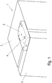
- a refrigerator 1 comprises a cabinet 3, on which a door 2 is rotatably mounted.
- a housing 5 with a Embodiment of a bearing arrangement according to the invention fixed.
- the bearing arrangement comprises a bearing axis 4 which is rotatably mounted in the housing and on which the door 2 is rotatably fixed.
- the housing 5 is fixed with the bearing arrangement on the top of the cabinet 3, but it is also possible to provide the bearing arrangement with the housing 5 on the bottom of the cabinet 3.
- a bearing arrangement is also arranged inside the cabinet 3, mounting on the outside having the advantage that retrofitting to existing refrigerators is possible.
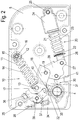
- the locking device 10 comprises a spring 11 designed as a compression spring, which is clamped between two end pieces 12 and 13.
- a first end piece 12 is rotatably mounted on the housing 5 about an axis 16.
- the end piece 13 is mounted about an axis 17 which is arranged on a rotatable actuating part 18.
- the rotatable actuating part 18 is rotatably mounted on the housing 5 about the axis 19.
- the spring 11 is guided around a sleeve 14 which can be pushed onto a rod 15 in order to be able to compensate for the length between the two end pieces 12 and 13.
- a damper 20 is also provided, which is designed as a linear pressure damper with a housing 21 and a piston rod 22.
- the piston rod 22 can be pushed into the housing 21, high damping forces being provided when the piston rod 22 is pushed in via a corresponding piston, while the piston rod 22 is pulled out smoothly.
- the housing 21 is fixed to a holder 24 which is rotatably mounted on the housing 5 about an axis 25.
- the piston rod 22 is connected on the opposite side via a holder 26 to a swivel part 28, the holder 26 being rotatably mounted about an axis 27.
- the swivel part 28 is rotatably mounted about the axis 19 on the housing 5, on which the actuating part 18 is also mounted, wherein the actuating part 18 and the swivel part 28 can be rotated independently of one another about the axis 19.
- a cam guide 30 is provided, which is arranged on the bearing axis 4 in a rotationally fixed manner.
- the Curve guide 30 comprises a plurality of control projections 31, 32 and 33, which act on the actuating part 18 and the pivoting part 28.
- a roller 40 is rotatably mounted on the actuating part 18, while a roller 41 is rotatably held on the pivoting part 28.
- the rollers can also be replaced by sliding elements, so that a process with as little friction as possible between the control projections and the actuating part or pivoting part 28 is ensured.
- a latching mechanism is provided in the housing 5 in order to latch the locking device 10 in a tensioned position, the latching mechanism comprising a pivotable latching pawl 35 which is mounted on the housing 5 such that it can rotate about the axis 38.
- the bearing axis 4 rotates the cam guide 30 counterclockwise, so that the first control projection 31 acts on the roller 40 in order to tension the spring 11 of the closing device 10.
- the damper 20 is released by rotating the control projection 31, whereby the pivoting part 28 rotates clockwise about the axis 19 until the pivoting part 28 stops 42 of the housing comes to rest.
- the pulling out of the piston rod 22 from the housing 21 and the associated pivoting of the pivoting part 28 takes place by means of the force of a spring 23 which is arranged between the holder 26 and the holder 24.
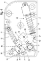
- the door 2 is arranged in an angular position of approximately 50 ° from the closed position.
- the damper 20 between the holder 24 and the holder 26 does not initially change its length when the closing device 10 is further tensioned by the control projection 31 acting on the roller 40 and thereby rotating the actuating part 18 further clockwise around the spring 11 of the closing device 10 compress.
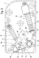
- a control cam 34 of the locking mechanism When opening the door between an opening angle of 35 ° ( Figure 3 ) and 50 ° ( Figure 4 ) a control cam 34 of the locking mechanism also engages with an arm 37 of the locking pawl 35 so that it is rotated about the axis 38. As a result, a second arm 36 of the essentially V-shaped latch 35 is pivoted to the actuating part 18. The control curve 34 rotates the pawl 35 against the force of a spring 39, which biases the pawl 35 in the unlocked position.
- the locking pawl By slightly compressing the spring 11 of the locking device 10 and a pivoting of the locking pawl 35 by the control cam 34, the locking pawl can be moved into the unlocked position by the locking pawl 35 being pivoted about the axis 38 by the force of the spring 39.
- the control projection 31 comes into engagement with the roller 41 at a closing angle between 20 ° and 60 ° in order to pivot the pivoting part 28 counterclockwise and thereby move the damper 20 into the compressed position , As a result, damping forces are also generated when the door 2 is closed.
- the locking device 10 is effective since it was unlocked via the control cam 34, so that the spring 11 now rotates the actuating part 18 counterclockwise about the axis 19, the roller 40 running on the rear of the control projection.
- the actuating part 18 of the closing device 10 and the pivoting part 28 of the damper 20 are partly actuated via the same control projections 31, which form a common curve. It is of course also possible to provide two separate cam guides on the bearing axis 4, one cam guide being exclusively responsible for the actuating part 18 and the second cam guide exclusively for the pivoting part 28. Furthermore, it is possible that the actuating part 18 and the pivoting part 28 are not mounted on a common axis 19. Each of these components can also have its own axis.
- the shape of the control projections 31, 32 and 33 can be matched to the respective application. For example, it is possible to make the damping forces larger in an angular range shortly before reaching the maximum closed position than in an opening range between 20 ° and 30 °.
- the spring 11 of the closing device 10 can also be controlled via the cam guide 30 in such a way that the closing forces are kept low in the closed position in order to keep the forces on the seals low, while the closing forces are made larger in a slightly open area.
- the bearing axis 4 can be designed as a separate bearing axis. This means that the bearing axis, for example, during assembly is already installed in the door and the bearing arrangement is plugged onto the bearing axis, so that the bearing axis is indirectly connected to the cam guide.
- bearing arrangement can also be mounted on an underside of a cabinet, as shown in Figure 10 is shown. Then a door is mounted on the bearing axis 4 protruding upwards.
- the bearing arrangement shown can be used on a right or left side of a cabinet 3 without the need for special right or left components.
Claims (13)
- Ensemble palier pour une porte (2), en particulier pour réfrigérateurs ou congélateurs, comportant un axe de palier (4) pour le montage rotatif de la porte (2), un dispositif de fermeture (10) au moyen duquel la porte (2) peut être déplacée dans la direction de fermeture sur une certaine plage de pivotement par la force d'un accumulateur d'énergie (11), un amortisseur (20) pour amortir un mouvement de pivotement de la porte (2) sur au moins une plage de pivotement, le dispositif de fermeture (10) et l'amortisseur (20) étant orientés dans un plan sensiblement perpendiculaire à l'axe de rotation de l'axe de palier (4), un guide courbe (30) étant disposé indirectement ou directement sur l'axe de palier (4), un premier guide courbe déplaçable par l'axe de palier (4) étant prévu pour déplacer le dispositif de fermeture (10) et au moins un deuxième guide courbe déplaçable par l'axe de palier (4) étant prévu pour déplacer l'amortisseur (20), caractérisé en ce qu'un mécanisme d'encliquetage est prévu pour encliqueter le dispositif de fermeture (10) dans un état tendu lorsque la porte (2) est ouverte, le mécanisme d'encliquetage présentant un cliquet (35) pouvant être actionné par une came de commande (34) de l'ensemble palier disposée indirectement ou directement sur l'axe de palier, et le cliquet (35) étant précontraint dans la position libérant l'encliquetage par un ressort (39) du mécanisme d'encliquetage.
- Ensemble palier selon la revendication 1, caractérisé en ce que les premier et deuxième guides courbes (30) sont reliés de manière solidaire en rotation à l'axe de palier (4).
- Ensemble palier selon la revendication 1 ou 2, caractérisé en ce que les premier et deuxième guides courbes (30) présentent des saillies de commande (31, 32, 33) qui peuvent agir sur le dispositif de fermeture (10) et/ou l'amortisseur (20).
- Ensemble palier selon l'une des revendications précédentes, caractérisé en ce que le deuxième guide courbe actionne l'amortisseur (20) pour amortir la porte (2) aussi bien dans la direction de fermeture avant l'atteinte de la position fermée que dans la direction d'ouverture avant l'atteinte de la position d'ouverture maximale.
- Ensemble palier selon l'une des revendications précédentes, caractérisé en ce que le dispositif de fermeture (10) et l'amortisseur (20) sont logés dans un boîtier (5).
- Ensemble palier selon la revendication 5, caractérisé en ce que l'amortisseur (20) est monté rotatif d'un côté sur le boîtier (5) et est maintenu rotatif sur une partie pivotante (28) du côté opposé.
- Ensemble palier selon la revendication 6, caractérisé en ce que le deuxième guide courbe présente des saillies de commande (31, 32, 33) qui agissent sur la partie pivotante (28) ou sur un galet (41) ou un élément coulissant disposé sur la partie pivotante (28).
- Ensemble palier selon l'une des revendications précédentes, caractérisé en ce que le dispositif de fermeture (10) présente un ressort (11), de préférence un ressort de compression (11), qui est serré entre deux pièces d'extrémité (12, 13).
- Ensemble palier selon la revendication 8, caractérisé en ce qu'une pièce d'extrémité (12) est montée rotative sur le boîtier (5) et la pièce d'extrémité opposée (13) est disposée sur une partie d'actionnement (18) montée rotative.
- Ensemble palier selon la revendication 9, caractérisé en ce que la partie d'actionnement (18) montée rotative peut être déplacée sur le premier guide courbe (30) par au moins une saillie de commande (31, 32), un galet rotatif (40) ou un élément coulissant, sur lequel agit ladite au moins une saillie de commande (31, 32), pouvant être prévu sur la partie d'actionnement (18).
- Ensemble palier selon l'une des revendications précédentes, caractérisé en ce que l'amortisseur (20) est réalisé sous la forme d'un amortisseur à pression linéaire qui produit une force d'amortissement plus élevée lorsqu'il est comprimé que lorsqu'il est étiré.
- Réfrigérateur ou congélateur (1) comportant au moins une porte pivotante (2) qui est maintenue sur une armoire (3) par au moins un ensemble palier selon l'une des revendications précédentes.
- Réfrigérateur ou congélateur selon la revendication 12, caractérisé en ce que l'ensemble palier est fixé sur un côté extérieur de l'armoire (3).
Priority Applications (1)
| Application Number | Priority Date | Filing Date | Title |
|---|---|---|---|
| PL15704295T PL3105396T3 (pl) | 2014-02-13 | 2015-02-11 | Układ łożyskowy dla drzwi |
Applications Claiming Priority (2)
| Application Number | Priority Date | Filing Date | Title |
|---|---|---|---|
| DE102014101849.4A DE102014101849A1 (de) | 2014-02-13 | 2014-02-13 | Lageranordnung für eine Tür |
| PCT/EP2015/052808 WO2015121271A1 (fr) | 2014-02-13 | 2015-02-11 | Ensemble palier de porte |
Publications (2)
| Publication Number | Publication Date |
|---|---|
| EP3105396A1 EP3105396A1 (fr) | 2016-12-21 |
| EP3105396B1 true EP3105396B1 (fr) | 2019-12-18 |
Family
ID=52469837
Family Applications (1)
| Application Number | Title | Priority Date | Filing Date |
|---|---|---|---|
| EP15704295.3A Active EP3105396B1 (fr) | 2014-02-13 | 2015-02-11 | Ensemble palier pour porte |
Country Status (11)
| Country | Link |
|---|---|
| US (1) | US9903146B2 (fr) |
| EP (1) | EP3105396B1 (fr) |
| JP (1) | JP6611360B2 (fr) |
| KR (1) | KR102251484B1 (fr) |
| CN (1) | CN105960500B (fr) |
| AU (1) | AU2015217669B2 (fr) |
| DE (1) | DE102014101849A1 (fr) |
| ES (1) | ES2779067T3 (fr) |
| PL (1) | PL3105396T3 (fr) |
| RU (1) | RU2674189C2 (fr) |
| WO (1) | WO2015121271A1 (fr) |
Families Citing this family (8)
| Publication number | Priority date | Publication date | Assignee | Title |
|---|---|---|---|---|
| CN206666870U (zh) * | 2016-12-30 | 2017-11-24 | 青岛海尔洗衣机有限公司 | 一种阻尼器及其洗衣机 |
| DE102017126367A1 (de) * | 2017-11-10 | 2019-05-16 | Hettich-Oni Gmbh & Co. Kg | Klappenbeschlag für ein Möbel, Seitenwand eines Möbelkorpus und Möbel mit einer Seitenwand |
| DE102017126366A1 (de) * | 2017-11-10 | 2019-05-16 | Hettich-Oni Gmbh & Co. Kg | Klappenbeschlag für ein Möbel, Seitenwand eines Möbelkorpus und Möbel mit einer Seitenwand |
| CN108061423B (zh) * | 2017-12-30 | 2020-10-30 | 青岛海尔股份有限公司 | 一种门体铰链机构及具有该门体铰链机构的冰箱 |
| CN108193966B (zh) * | 2017-12-30 | 2021-03-23 | 海尔智家股份有限公司 | 一种门体铰链机构及具有该门体铰链机构的冰箱 |
| EP3850178B1 (fr) * | 2018-09-14 | 2022-11-23 | C.M.I. Cerniere Meccaniche Industriali S.r.L. | Dispositif articulé pour appareils et meubles avec amortissement de la vitesse de fin de course |
| CN111140114B (zh) * | 2020-03-10 | 2021-05-14 | 长虹美菱股份有限公司 | 一种冰箱铰链组件 |
| US11536070B2 (en) * | 2020-06-04 | 2022-12-27 | Whirlpool Corporation | Dish treating appliance with a door opener |
Citations (3)
| Publication number | Priority date | Publication date | Assignee | Title |
|---|---|---|---|---|
| GB408782A (en) * | 1933-02-15 | 1934-04-19 | Newman William & Sons Ltd | Improvements in door closing and checking appliances |
| GB925095A (en) * | 1960-09-02 | 1963-05-01 | Ver Baubeschlag Gretsch Co | Improvements in or relating to door closing and checking devices |
| US20090033189A1 (en) * | 2007-08-03 | 2009-02-05 | Dorma Gmbh + Co. Kg | Door Actuation Device for Actuating the Door of a Refrigerator/Freezer Cabinet |
Family Cites Families (17)
| Publication number | Priority date | Publication date | Assignee | Title |
|---|---|---|---|---|
| US2603818A (en) * | 1948-04-12 | 1952-07-22 | George W Houlsby Jr | Door check mechanism |
| GB1050496A (fr) * | 1963-12-24 | 1900-01-01 | ||
| DE1807399A1 (de) * | 1968-11-07 | 1970-05-27 | Doerken & Mankel Kg | Selbsttaetiger Tuerschliesser |
| FR2045128A5 (fr) * | 1969-06-04 | 1971-02-26 | Verrieres Appliq Et | |
| DE2010580A1 (de) * | 1970-03-06 | 1971-09-16 | Vereinigte Baubeschlagfabriken Gretsch & Co Gmbh, 7250 Leonberg | Türschließer |
| US3773311A (en) * | 1971-09-27 | 1973-11-20 | Hartwell Corp | Overhead door control device |
| GB1344945A (en) * | 1972-01-06 | 1974-01-23 | Gibbons Ld James | Doorclosing mechanism |
| DE2522410A1 (de) * | 1975-05-21 | 1977-01-20 | Ver Baubeschlag Gretsch Co | Bodentuerschliesser |
| DE2620386C3 (de) * | 1976-05-08 | 1980-08-28 | Vereinigte Baubeschlagfabriken Gretsch & Co Gmbh, 7250 Leonberg | Feststellvorrichtung für einen Türschließer |
| DE2608671A1 (de) * | 1976-03-03 | 1977-09-08 | Dorma Baubeschlag | Selbsttaetiger tuerschliesser |
| JP4076528B2 (ja) * | 2004-08-30 | 2008-04-16 | 日立アプライアンス株式会社 | 冷蔵庫扉閉鎖装置 |
| CN101093131B (zh) * | 2006-06-21 | 2010-12-29 | 海尔集团公司 | 电冰箱 |
| DE202006010482U1 (de) | 2006-07-06 | 2007-11-08 | Liebherr-Hausgeräte Lienz Gmbh | Anordnung zur schwenkbaren Lagerung einer Tür oder Klappe sowie Kühl- und/oder Gefriergeräte mit einer derartigen Anordnung |
| DE202007005957U1 (de) * | 2007-02-19 | 2008-06-26 | Liebherr-Hausgeräte Ochsenhausen GmbH | Kühl- und/oder Gefriergerät |
| DE102009034742A1 (de) * | 2009-07-24 | 2011-02-03 | Dorma Gmbh + Co. Kg | Türschließer |
| GB2479145A (en) * | 2010-03-29 | 2011-10-05 | Ingersoll Rand Security Technologies Ltd | Door closer having two springs |
| EP3730729B1 (fr) * | 2014-01-27 | 2024-04-24 | In & Tec S.r.l. | Charnière à faible encombrement |
-
2014
- 2014-02-13 DE DE102014101849.4A patent/DE102014101849A1/de not_active Withdrawn
-
2015
- 2015-02-11 WO PCT/EP2015/052808 patent/WO2015121271A1/fr active Application Filing
- 2015-02-11 US US15/118,317 patent/US9903146B2/en active Active
- 2015-02-11 JP JP2016551802A patent/JP6611360B2/ja not_active Expired - Fee Related
- 2015-02-11 PL PL15704295T patent/PL3105396T3/pl unknown
- 2015-02-11 RU RU2016133848A patent/RU2674189C2/ru active
- 2015-02-11 ES ES15704295T patent/ES2779067T3/es active Active
- 2015-02-11 KR KR1020167022852A patent/KR102251484B1/ko active IP Right Grant
- 2015-02-11 AU AU2015217669A patent/AU2015217669B2/en not_active Ceased
- 2015-02-11 EP EP15704295.3A patent/EP3105396B1/fr active Active
- 2015-02-11 CN CN201580007420.5A patent/CN105960500B/zh active Active
Patent Citations (3)
| Publication number | Priority date | Publication date | Assignee | Title |
|---|---|---|---|---|
| GB408782A (en) * | 1933-02-15 | 1934-04-19 | Newman William & Sons Ltd | Improvements in door closing and checking appliances |
| GB925095A (en) * | 1960-09-02 | 1963-05-01 | Ver Baubeschlag Gretsch Co | Improvements in or relating to door closing and checking devices |
| US20090033189A1 (en) * | 2007-08-03 | 2009-02-05 | Dorma Gmbh + Co. Kg | Door Actuation Device for Actuating the Door of a Refrigerator/Freezer Cabinet |
Also Published As
| Publication number | Publication date |
|---|---|
| US20170175429A1 (en) | 2017-06-22 |
| RU2016133848A3 (fr) | 2018-08-23 |
| JP2017511848A (ja) | 2017-04-27 |
| JP6611360B2 (ja) | 2019-11-27 |
| KR102251484B1 (ko) | 2021-05-12 |
| RU2016133848A (ru) | 2018-03-16 |
| WO2015121271A1 (fr) | 2015-08-20 |
| RU2674189C2 (ru) | 2018-12-05 |
| EP3105396A1 (fr) | 2016-12-21 |
| DE102014101849A1 (de) | 2015-08-13 |
| US9903146B2 (en) | 2018-02-27 |
| AU2015217669B2 (en) | 2019-01-03 |
| CN105960500B (zh) | 2018-05-01 |
| AU2015217669A1 (en) | 2016-07-28 |
| CN105960500A (zh) | 2016-09-21 |
| ES2779067T3 (es) | 2020-08-13 |
| KR20160124114A (ko) | 2016-10-26 |
| PL3105396T3 (pl) | 2020-06-01 |
Similar Documents
| Publication | Publication Date | Title |
|---|---|---|
| EP3105396B1 (fr) | Ensemble palier pour porte | |
| DE202018105095U1 (de) | Tür- und Treppenschutzgitter mit ausrollbarer Trennwand | |
| DE102011083512A1 (de) | Haushaltsgerät mit einem Aufnahmeraum und einer Tür zum Verschließen des Aufnahmeraums, sowie Verfahren zum Betätigen einer Tür eines Haushaltsgeräts | |
| EP3336292B1 (fr) | Procédé d'actionnement d'une serrure de porte et serrure de porte | |
| DE102009029023A1 (de) | Kraftfahrzeugschloss | |
| WO2014195474A1 (fr) | Ferme-porte pour battant de porte ou fenêtre | |
| DE102012111085B4 (de) | Türöffner | |
| EP2949842B1 (fr) | Système de poignée de porte pour un véhicule | |
| EP3487359B1 (fr) | Dispositif d'éjection pour un élément de meuble mobile et meuble | |
| EP3143227B1 (fr) | Ensemble de palier pour une porte | |
| DE102016118139A1 (de) | Trennscheibe für Paniknuss | |
| DE202011105510U1 (de) | Türöffner mit Sperr-Riegel | |
| DE102012009067B3 (de) | Aufschlagsicherer Türöffner | |
| DE102011119333B3 (de) | Feststellvorrichtung für eine Tür, vorzugsweise mit Türschließer | |
| DE102017119252A1 (de) | Funktionskomponente einer Kraftfahrzeugschlossanordnung | |
| DE10211704C1 (de) | Verschluß für Kühlräume | |
| EP1672153B1 (fr) | Serrure avec pêne dormant et dispositif de commande du pêne dormant | |
| EP1959076B1 (fr) | Automate de fermeture pour un battant de porte ou de fenêtre | |
| DE3916836C1 (en) | Actuating mechanism for sealing door esp. for EM screening - has rotating shaft with connecting lever closing door against stop-bands on door frame | |
| DE102012010438B4 (de) | Türöffner mit Sperr-Riegel | |
| DE102016010445B4 (de) | Flügelschloss | |
| EP3122964B1 (fr) | Serrure pour porte ou fenêtre | |
| DE202015101338U1 (de) | Verschluss | |
| WO2022175007A1 (fr) | Système comprenant un appareil de cuisson doté d'une chambre de cuisson, et appareil de cuisson doté d'une chambre de cuisson | |
| DE102013103479A1 (de) | Türöffner |
Legal Events
| Date | Code | Title | Description |
|---|---|---|---|
| PUAI | Public reference made under article 153(3) epc to a published international application that has entered the european phase |
Free format text: ORIGINAL CODE: 0009012 |
|
| STAA | Information on the status of an ep patent application or granted ep patent |
Free format text: STATUS: REQUEST FOR EXAMINATION WAS MADE |
|
| 17P | Request for examination filed |
Effective date: 20160712 |
|
| AK | Designated contracting states |
Kind code of ref document: A1 Designated state(s): AL AT BE BG CH CY CZ DE DK EE ES FI FR GB GR HR HU IE IS IT LI LT LU LV MC MK MT NL NO PL PT RO RS SE SI SK SM TR |
|
| AX | Request for extension of the european patent |
Extension state: BA ME |
|
| DAX | Request for extension of the european patent (deleted) | ||
| STAA | Information on the status of an ep patent application or granted ep patent |
Free format text: STATUS: EXAMINATION IS IN PROGRESS |
|
| 17Q | First examination report despatched |
Effective date: 20171124 |
|
| GRAP | Despatch of communication of intention to grant a patent |
Free format text: ORIGINAL CODE: EPIDOSNIGR1 |
|
| STAA | Information on the status of an ep patent application or granted ep patent |
Free format text: STATUS: GRANT OF PATENT IS INTENDED |
|
| INTG | Intention to grant announced |
Effective date: 20190731 |
|
| GRAS | Grant fee paid |
Free format text: ORIGINAL CODE: EPIDOSNIGR3 |
|
| GRAA | (expected) grant |
Free format text: ORIGINAL CODE: 0009210 |
|
| STAA | Information on the status of an ep patent application or granted ep patent |
Free format text: STATUS: THE PATENT HAS BEEN GRANTED |
|
| AK | Designated contracting states |
Kind code of ref document: B1 Designated state(s): AL AT BE BG CH CY CZ DE DK EE ES FI FR GB GR HR HU IE IS IT LI LT LU LV MC MK MT NL NO PL PT RO RS SE SI SK SM TR |
|
| REG | Reference to a national code |
Ref country code: CH Ref legal event code: EP |
|
| REG | Reference to a national code |
Ref country code: IE Ref legal event code: FG4D Free format text: LANGUAGE OF EP DOCUMENT: GERMAN |
|
| REG | Reference to a national code |
Ref country code: DE Ref legal event code: R096 Ref document number: 502015011252 Country of ref document: DE |
|
| REG | Reference to a national code |
Ref country code: AT Ref legal event code: REF Ref document number: 1214770 Country of ref document: AT Kind code of ref document: T Effective date: 20200115 |
|
| REG | Reference to a national code |
Ref country code: NL Ref legal event code: MP Effective date: 20191218 |
|
| PG25 | Lapsed in a contracting state [announced via postgrant information from national office to epo] |
Ref country code: FI Free format text: LAPSE BECAUSE OF FAILURE TO SUBMIT A TRANSLATION OF THE DESCRIPTION OR TO PAY THE FEE WITHIN THE PRESCRIBED TIME-LIMIT Effective date: 20191218 Ref country code: BG Free format text: LAPSE BECAUSE OF FAILURE TO SUBMIT A TRANSLATION OF THE DESCRIPTION OR TO PAY THE FEE WITHIN THE PRESCRIBED TIME-LIMIT Effective date: 20200318 Ref country code: SE Free format text: LAPSE BECAUSE OF FAILURE TO SUBMIT A TRANSLATION OF THE DESCRIPTION OR TO PAY THE FEE WITHIN THE PRESCRIBED TIME-LIMIT Effective date: 20191218 Ref country code: LV Free format text: LAPSE BECAUSE OF FAILURE TO SUBMIT A TRANSLATION OF THE DESCRIPTION OR TO PAY THE FEE WITHIN THE PRESCRIBED TIME-LIMIT Effective date: 20191218 Ref country code: LT Free format text: LAPSE BECAUSE OF FAILURE TO SUBMIT A TRANSLATION OF THE DESCRIPTION OR TO PAY THE FEE WITHIN THE PRESCRIBED TIME-LIMIT Effective date: 20191218 Ref country code: NO Free format text: LAPSE BECAUSE OF FAILURE TO SUBMIT A TRANSLATION OF THE DESCRIPTION OR TO PAY THE FEE WITHIN THE PRESCRIBED TIME-LIMIT Effective date: 20200318 Ref country code: GR Free format text: LAPSE BECAUSE OF FAILURE TO SUBMIT A TRANSLATION OF THE DESCRIPTION OR TO PAY THE FEE WITHIN THE PRESCRIBED TIME-LIMIT Effective date: 20200319 |
|
| REG | Reference to a national code |
Ref country code: LT Ref legal event code: MG4D |
|
| PG25 | Lapsed in a contracting state [announced via postgrant information from national office to epo] |
Ref country code: HR Free format text: LAPSE BECAUSE OF FAILURE TO SUBMIT A TRANSLATION OF THE DESCRIPTION OR TO PAY THE FEE WITHIN THE PRESCRIBED TIME-LIMIT Effective date: 20191218 Ref country code: RS Free format text: LAPSE BECAUSE OF FAILURE TO SUBMIT A TRANSLATION OF THE DESCRIPTION OR TO PAY THE FEE WITHIN THE PRESCRIBED TIME-LIMIT Effective date: 20191218 |
|
| PG25 | Lapsed in a contracting state [announced via postgrant information from national office to epo] |
Ref country code: AL Free format text: LAPSE BECAUSE OF FAILURE TO SUBMIT A TRANSLATION OF THE DESCRIPTION OR TO PAY THE FEE WITHIN THE PRESCRIBED TIME-LIMIT Effective date: 20191218 |
|
| PG25 | Lapsed in a contracting state [announced via postgrant information from national office to epo] |
Ref country code: PT Free format text: LAPSE BECAUSE OF FAILURE TO SUBMIT A TRANSLATION OF THE DESCRIPTION OR TO PAY THE FEE WITHIN THE PRESCRIBED TIME-LIMIT Effective date: 20200513 Ref country code: NL Free format text: LAPSE BECAUSE OF FAILURE TO SUBMIT A TRANSLATION OF THE DESCRIPTION OR TO PAY THE FEE WITHIN THE PRESCRIBED TIME-LIMIT Effective date: 20191218 Ref country code: CZ Free format text: LAPSE BECAUSE OF FAILURE TO SUBMIT A TRANSLATION OF THE DESCRIPTION OR TO PAY THE FEE WITHIN THE PRESCRIBED TIME-LIMIT Effective date: 20191218 Ref country code: RO Free format text: LAPSE BECAUSE OF FAILURE TO SUBMIT A TRANSLATION OF THE DESCRIPTION OR TO PAY THE FEE WITHIN THE PRESCRIBED TIME-LIMIT Effective date: 20191218 Ref country code: EE Free format text: LAPSE BECAUSE OF FAILURE TO SUBMIT A TRANSLATION OF THE DESCRIPTION OR TO PAY THE FEE WITHIN THE PRESCRIBED TIME-LIMIT Effective date: 20191218 |
|
| REG | Reference to a national code |
Ref country code: ES Ref legal event code: FG2A Ref document number: 2779067 Country of ref document: ES Kind code of ref document: T3 Effective date: 20200813 |
|
| PG25 | Lapsed in a contracting state [announced via postgrant information from national office to epo] |
Ref country code: SM Free format text: LAPSE BECAUSE OF FAILURE TO SUBMIT A TRANSLATION OF THE DESCRIPTION OR TO PAY THE FEE WITHIN THE PRESCRIBED TIME-LIMIT Effective date: 20191218 Ref country code: IS Free format text: LAPSE BECAUSE OF FAILURE TO SUBMIT A TRANSLATION OF THE DESCRIPTION OR TO PAY THE FEE WITHIN THE PRESCRIBED TIME-LIMIT Effective date: 20200418 Ref country code: SK Free format text: LAPSE BECAUSE OF FAILURE TO SUBMIT A TRANSLATION OF THE DESCRIPTION OR TO PAY THE FEE WITHIN THE PRESCRIBED TIME-LIMIT Effective date: 20191218 |
|
| REG | Reference to a national code |
Ref country code: DE Ref legal event code: R097 Ref document number: 502015011252 Country of ref document: DE |
|
| REG | Reference to a national code |
Ref country code: CH Ref legal event code: PL |
|
| PLBE | No opposition filed within time limit |
Free format text: ORIGINAL CODE: 0009261 |
|
| STAA | Information on the status of an ep patent application or granted ep patent |
Free format text: STATUS: NO OPPOSITION FILED WITHIN TIME LIMIT |
|
| REG | Reference to a national code |
Ref country code: BE Ref legal event code: MM Effective date: 20200229 |
|
| PG25 | Lapsed in a contracting state [announced via postgrant information from national office to epo] |
Ref country code: DK Free format text: LAPSE BECAUSE OF FAILURE TO SUBMIT A TRANSLATION OF THE DESCRIPTION OR TO PAY THE FEE WITHIN THE PRESCRIBED TIME-LIMIT Effective date: 20191218 Ref country code: LU Free format text: LAPSE BECAUSE OF NON-PAYMENT OF DUE FEES Effective date: 20200211 Ref country code: MC Free format text: LAPSE BECAUSE OF FAILURE TO SUBMIT A TRANSLATION OF THE DESCRIPTION OR TO PAY THE FEE WITHIN THE PRESCRIBED TIME-LIMIT Effective date: 20191218 |
|
| 26N | No opposition filed |
Effective date: 20200921 |
|
| PG25 | Lapsed in a contracting state [announced via postgrant information from national office to epo] |
Ref country code: LI Free format text: LAPSE BECAUSE OF NON-PAYMENT OF DUE FEES Effective date: 20200229 Ref country code: SI Free format text: LAPSE BECAUSE OF FAILURE TO SUBMIT A TRANSLATION OF THE DESCRIPTION OR TO PAY THE FEE WITHIN THE PRESCRIBED TIME-LIMIT Effective date: 20191218 Ref country code: CH Free format text: LAPSE BECAUSE OF NON-PAYMENT OF DUE FEES Effective date: 20200229 |
|
| PG25 | Lapsed in a contracting state [announced via postgrant information from national office to epo] |
Ref country code: FR Free format text: LAPSE BECAUSE OF NON-PAYMENT OF DUE FEES Effective date: 20200218 Ref country code: IE Free format text: LAPSE BECAUSE OF NON-PAYMENT OF DUE FEES Effective date: 20200211 |
|
| PG25 | Lapsed in a contracting state [announced via postgrant information from national office to epo] |
Ref country code: BE Free format text: LAPSE BECAUSE OF NON-PAYMENT OF DUE FEES Effective date: 20200229 |
|
| GBPC | Gb: european patent ceased through non-payment of renewal fee |
Effective date: 20200318 |
|
| PG25 | Lapsed in a contracting state [announced via postgrant information from national office to epo] |
Ref country code: GB Free format text: LAPSE BECAUSE OF NON-PAYMENT OF DUE FEES Effective date: 20200318 |
|
| PGFP | Annual fee paid to national office [announced via postgrant information from national office to epo] |
Ref country code: TR Payment date: 20210205 Year of fee payment: 7 Ref country code: PL Payment date: 20210129 Year of fee payment: 7 Ref country code: AT Payment date: 20210216 Year of fee payment: 7 Ref country code: ES Payment date: 20210323 Year of fee payment: 7 |
|
| PG25 | Lapsed in a contracting state [announced via postgrant information from national office to epo] |
Ref country code: MT Free format text: LAPSE BECAUSE OF FAILURE TO SUBMIT A TRANSLATION OF THE DESCRIPTION OR TO PAY THE FEE WITHIN THE PRESCRIBED TIME-LIMIT Effective date: 20191218 Ref country code: CY Free format text: LAPSE BECAUSE OF FAILURE TO SUBMIT A TRANSLATION OF THE DESCRIPTION OR TO PAY THE FEE WITHIN THE PRESCRIBED TIME-LIMIT Effective date: 20191218 |
|
| PG25 | Lapsed in a contracting state [announced via postgrant information from national office to epo] |
Ref country code: MK Free format text: LAPSE BECAUSE OF FAILURE TO SUBMIT A TRANSLATION OF THE DESCRIPTION OR TO PAY THE FEE WITHIN THE PRESCRIBED TIME-LIMIT Effective date: 20191218 |
|
| REG | Reference to a national code |
Ref country code: AT Ref legal event code: MM01 Ref document number: 1214770 Country of ref document: AT Kind code of ref document: T Effective date: 20220211 |
|
| PG25 | Lapsed in a contracting state [announced via postgrant information from national office to epo] |
Ref country code: AT Free format text: LAPSE BECAUSE OF NON-PAYMENT OF DUE FEES Effective date: 20220211 |
|
| REG | Reference to a national code |
Ref country code: ES Ref legal event code: FD2A Effective date: 20230403 |
|
| PG25 | Lapsed in a contracting state [announced via postgrant information from national office to epo] |
Ref country code: ES Free format text: LAPSE BECAUSE OF NON-PAYMENT OF DUE FEES Effective date: 20220212 |
|
| PG25 | Lapsed in a contracting state [announced via postgrant information from national office to epo] |
Ref country code: PL Free format text: LAPSE BECAUSE OF NON-PAYMENT OF DUE FEES Effective date: 20220211 |
|
| PGFP | Annual fee paid to national office [announced via postgrant information from national office to epo] |
Ref country code: IT Payment date: 20230228 Year of fee payment: 9 |
|
| P01 | Opt-out of the competence of the unified patent court (upc) registered |
Effective date: 20230410 |
|
| PGFP | Annual fee paid to national office [announced via postgrant information from national office to epo] |
Ref country code: DE Payment date: 20240216 Year of fee payment: 10 |