EP3105135B1 - Multipurpose dispenser for spreadable wall repair compound - Google Patents
Multipurpose dispenser for spreadable wall repair compound Download PDFInfo
- Publication number
- EP3105135B1 EP3105135B1 EP15746924.8A EP15746924A EP3105135B1 EP 3105135 B1 EP3105135 B1 EP 3105135B1 EP 15746924 A EP15746924 A EP 15746924A EP 3105135 B1 EP3105135 B1 EP 3105135B1
- Authority
- EP
- European Patent Office
- Prior art keywords
- container
- tail portion
- wall
- abrasive
- cap member
- Prior art date
- Legal status (The legal status is an assumption and is not a legal conclusion. Google has not performed a legal analysis and makes no representation as to the accuracy of the status listed.)
- Active
Links
- 230000008439 repair process Effects 0.000 title claims description 14
- 150000001875 compounds Chemical class 0.000 title description 19
- 239000000463 material Substances 0.000 claims description 58
- 230000009969 flowable effect Effects 0.000 claims description 41
- 238000009499 grossing Methods 0.000 claims description 6
- 239000006260 foam Substances 0.000 claims description 5
- 239000000853 adhesive Substances 0.000 claims description 4
- 230000001070 adhesive effect Effects 0.000 claims description 4
- 238000010276 construction Methods 0.000 claims description 4
- 229920001903 high density polyethylene Polymers 0.000 claims description 3
- 239000004700 high-density polyethylene Substances 0.000 claims description 3
- 229920001684 low density polyethylene Polymers 0.000 claims description 3
- 239000004702 low-density polyethylene Substances 0.000 claims description 3
- 239000000758 substrate Substances 0.000 claims description 3
- 230000013011 mating Effects 0.000 claims description 2
- 230000003014 reinforcing effect Effects 0.000 claims description 2
- 239000012530 fluid Substances 0.000 description 9
- 239000004576 sand Substances 0.000 description 6
- -1 spackling compound Chemical class 0.000 description 4
- 230000007812 deficiency Effects 0.000 description 3
- 230000007480 spreading Effects 0.000 description 3
- 239000004698 Polyethylene Substances 0.000 description 2
- 238000007796 conventional method Methods 0.000 description 2
- 238000010030 laminating Methods 0.000 description 2
- 238000000034 method Methods 0.000 description 2
- 239000000123 paper Substances 0.000 description 2
- 239000002245 particle Substances 0.000 description 2
- 229920000573 polyethylene Polymers 0.000 description 2
- 229910052782 aluminium Inorganic materials 0.000 description 1
- XAGFODPZIPBFFR-UHFFFAOYSA-N aluminium Chemical compound [Al] XAGFODPZIPBFFR-UHFFFAOYSA-N 0.000 description 1
- 230000004888 barrier function Effects 0.000 description 1
- 230000015572 biosynthetic process Effects 0.000 description 1
- 238000000748 compression moulding Methods 0.000 description 1
- 238000013461 design Methods 0.000 description 1
- 238000005553 drilling Methods 0.000 description 1
- 238000010101 extrusion blow moulding Methods 0.000 description 1
- 239000011888 foil Substances 0.000 description 1
- 230000006870 function Effects 0.000 description 1
- 239000002223 garnet Substances 0.000 description 1
- 238000010102 injection blow moulding Methods 0.000 description 1
- 239000007788 liquid Substances 0.000 description 1
- 229910052751 metal Inorganic materials 0.000 description 1
- 239000002184 metal Substances 0.000 description 1
- 238000012986 modification Methods 0.000 description 1
- 230000004048 modification Effects 0.000 description 1
- TWNQGVIAIRXVLR-UHFFFAOYSA-N oxo(oxoalumanyloxy)alumane Chemical compound O=[Al]O[Al]=O TWNQGVIAIRXVLR-UHFFFAOYSA-N 0.000 description 1
- 229920003023 plastic Polymers 0.000 description 1
- 239000004033 plastic Substances 0.000 description 1
- 238000012805 post-processing Methods 0.000 description 1
- 238000003825 pressing Methods 0.000 description 1
- HBMJWWWQQXIZIP-UHFFFAOYSA-N silicon carbide Chemical compound [Si+]#[C-] HBMJWWWQQXIZIP-UHFFFAOYSA-N 0.000 description 1
- 229910010271 silicon carbide Inorganic materials 0.000 description 1
Images


Classifications
-
- B—PERFORMING OPERATIONS; TRANSPORTING
- B65—CONVEYING; PACKING; STORING; HANDLING THIN OR FILAMENTARY MATERIAL
- B65D—CONTAINERS FOR STORAGE OR TRANSPORT OF ARTICLES OR MATERIALS, e.g. BAGS, BARRELS, BOTTLES, BOXES, CANS, CARTONS, CRATES, DRUMS, JARS, TANKS, HOPPERS, FORWARDING CONTAINERS; ACCESSORIES, CLOSURES, OR FITTINGS THEREFOR; PACKAGING ELEMENTS; PACKAGES
- B65D35/00—Pliable tubular containers adapted to be permanently or temporarily deformed to expel contents, e.g. collapsible tubes for toothpaste or other plastic or semi-liquid material; Holders therefor
- B65D35/24—Pliable tubular containers adapted to be permanently or temporarily deformed to expel contents, e.g. collapsible tubes for toothpaste or other plastic or semi-liquid material; Holders therefor with auxiliary devices
- B65D35/36—Pliable tubular containers adapted to be permanently or temporarily deformed to expel contents, e.g. collapsible tubes for toothpaste or other plastic or semi-liquid material; Holders therefor with auxiliary devices for applying contents to surfaces
-
- B—PERFORMING OPERATIONS; TRANSPORTING
- B65—CONVEYING; PACKING; STORING; HANDLING THIN OR FILAMENTARY MATERIAL
- B65D—CONTAINERS FOR STORAGE OR TRANSPORT OF ARTICLES OR MATERIALS, e.g. BAGS, BARRELS, BOTTLES, BOXES, CANS, CARTONS, CRATES, DRUMS, JARS, TANKS, HOPPERS, FORWARDING CONTAINERS; ACCESSORIES, CLOSURES, OR FITTINGS THEREFOR; PACKAGING ELEMENTS; PACKAGES
- B65D41/00—Caps, e.g. crown caps or crown seals, i.e. members having parts arranged for engagement with the external periphery of a neck or wall defining a pouring opening or discharge aperture; Protective cap-like covers for closure members, e.g. decorative covers of metal foil or paper
- B65D41/02—Caps or cap-like covers without lines of weakness, tearing strips, tags, or like opening or removal devices
- B65D41/04—Threaded or like caps or cap-like covers secured by rotation
-
- B—PERFORMING OPERATIONS; TRANSPORTING
- B65—CONVEYING; PACKING; STORING; HANDLING THIN OR FILAMENTARY MATERIAL
- B65D—CONTAINERS FOR STORAGE OR TRANSPORT OF ARTICLES OR MATERIALS, e.g. BAGS, BARRELS, BOTTLES, BOXES, CANS, CARTONS, CRATES, DRUMS, JARS, TANKS, HOPPERS, FORWARDING CONTAINERS; ACCESSORIES, CLOSURES, OR FITTINGS THEREFOR; PACKAGING ELEMENTS; PACKAGES
- B65D51/00—Closures not otherwise provided for
- B65D51/24—Closures not otherwise provided for combined or co-operating with auxiliary devices for non-closing purposes
- B65D51/28—Closures not otherwise provided for combined or co-operating with auxiliary devices for non-closing purposes with auxiliary containers for additional articles or materials
Definitions
- the present invention relates generally to containers for dispensing flowable materials and, more particularly, to a flexible tube-like container that can be manually squeezed to dispense the flowable material from the tube.
- Wall repair compounds such as spackle (also referred to as spackling compound), are commonly used to repair cracks, holes, or other imperfections in a wall caused by, for example, nails, drilling, or impact before the wall is painted or otherwise finished. Repairing a damaged wall surface using spackle typically involves applying one or more coats of spackling compound to the wall surface using a tool such as a putty knife. Spackling compound is typically sold in tubs having openings that are large enough for the putty knife to be dipped into the tub and coated with spackling compound. The putty knife can then be used to apply the spackling compound to the wall surface and spread it evenly on the wall surface. After the spackling compound has dried and hardened, it can be sanded smooth using a conventional abrasive such as sandpaper or a sanding sponge.
- a conventional abrasive such as sandpaper or a sanding sponge.
- Tube dispensers are known in the prior art.
- U.S. Patent No. 5,577,851 discloses a tube dispenser, sponge applicator and cover assembly including a tube dispenser having a main body portion, an upper neck portion extending from the main body at an upper end and an upper circumferential portion at the upper end of the main body portion adjacent to the neck portion.
- U.S. Patent No. 7,744,299 discloses a dispensing system for patching an untextured portion of a destination surface to substantially match an existing structure of an existing sprayed on texture pattern on the destination surface surrounding the untextured portion.
- the dispensing system comprises a container, a sponge member, and a scraper member.
- WO 2005/039991 discloses a container that may hold liquids of varying viscosity, the container having a dispenser cap at one end and a non-collapsible tail portion at the other end.
- US 2006/285913 describes a dispenser cap with an applicator connected to a container with a non-collapsible tail portion. The container may hold various fluid materials.
- WO 2006/089824 discloses a dispensing tube comprising a tubular body which is closed at one end and has a non-collapsible tail portion, and further has, at its other end, an opening for dispensing the contained fluid product.
- US 5 638 990 discloses a container for viscous fluids or materials, such as wall patching compound, including a hollow, flexible, tubular body having a spreading knife mounted to an end thereof.
- the methods and dispensers of the prior art suffer from a number of deficiencies.
- the conventional method of applying wall repair compound, such as spackling compound requires the user to have three separate items to complete the task, namely, the container of spackling compound, a putty knife, and an abrasive.
- the prior art dispensers fail to overcome these deficiencies. It would be desirable to provide a multipurpose container that overcomes these deficiencies.
- the present disclosure provides a multipurpose container for dispensing a flowable wall repair material, such as spackle.
- the container includes a body member having a neck portion containing an opening for dispensing the flowable material, a collapsible mid portion adjacent the neck portion, and a, and a non-collapsible tail portion adjacent the mid portion that serves as a blade for smoothing the flowable material after the flowable material has been dispensed from the container.
- the container may include a tapered shoulder portion adjacent the neck portion
- the body member may be a flexible tube flattened at one end
- the unflattened portion of the tube may include tapered side walls that form a portion of the mid portion
- the flattened end may form the tail portion of the body member
- the mid portion and tail portion may have a unitary one-piece construction
- the mid portion may be an elongated hollow tube having a wall defining a chamber for receiving the flowable material
- the tail portion may be generally flat and extend from the mid portion
- the tail portion may be formed by opposed portions of the wall brought into contact with each other
- the body member may be formed of high or low density polyethylene
- the wall may have a thickness of at least about 0.2 millimeter and a thickness of no greater than about 5 millimeters
- the tail portion may have a length of at least about 8 millimeters and a length of no greater than about 60 millimeters
- the tail portion may have opposed major surfaces including elongated recessed regions
- the container provides a body member that allows a user to readily dispense a flowable material from the container by squeezing the body member while also providing a tail portion that is large enough and stiff enough to serve as a putty knife for spreading the flowable material after is has been dispensed from the container.
- the container includes a cap and abrasive assembly that allow a user to sand the flowable material after is has been allowed to dry and harden.
- the container provides a multipurpose all-in-one dispenser system that provides a user with all of the items needed to complete a wall repair project.
- the container contains wall repair compound, such as spackling, that can be readily dispensed by squeezing the container
- the container includes a unitary tail portion that serves as a putty knife for spreading the wall repair compound after it has been dispensed from the container
- the container includes a cap member and an abrasive assembly, whereby the abrasive assembly can be connected with the cap member to conveniently store the abrasive assembly, and the abrasive assembly can be separated from the cap member, whereby the user can sand the wall repair compound to a smooth surface after the wall repair compound has dried and hardened.
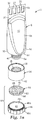
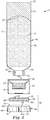
- FIGS. 1-5 show a container 2 for dispensing a flowable material 4 which may be, for example, a wall repair compound, such as spackling compound or the like.
- the container 2 includes a body member 6 having a neck portion 6a containing an exit orifice or opening 8 for dispensing the flowable material, a collapsible mid portion 6b adjacent the neck portion 6a, and a flexible but generally stiff non-collapsible tail portion 6c adjacent the mid portion 6b that serves as a blade for smoothing the flowable material 4 after the flowable material 4 has been dispensed from the container 2.
- the container 2 may include an optional moisture barrier (not shown), such an adhesive tab, that initially covers the opening 8, or the container may be initially closed, whereby the opening 8 may be formed by an end user by piercing the neck portion 6a with a sharp object, such as a knife, nail, or screw driver.
- an optional moisture barrier such an adhesive tab, that initially covers the opening 8, or the container may be initially closed, whereby the opening 8 may be formed by an end user by piercing the neck portion 6a with a sharp object, such as a knife, nail, or screw driver.
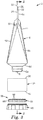
- the body member 6 includes a shoulder portion 6d that flairs outwardly and extends from the neck portion 6a to the mid portion 6b.
- the body member 6 generally has the shape of a hollow tube that has been flattened at one end, and the flattened end forms the tail portion 6c.
- the shoulder portion 6d of the body member 6, as well as the region of the body member 6 adjacent the shoulder portion 6d, has a generally circular cross-section, and the body member 6 is tapered and becomes progressively narrower in the direction away from the neck portion 6a as shown most clearly in FIGS. 3 and 4 . More specifically, the body member 6 has opposed generally flat front and back surfaces 10, 12 that taper inwardly toward each other as they get closer to the tail portion 6c, and curved side surfaces 14, 16 that remain generally parallel along the length of the body member 6.
- the tapered portion of the tube forms the mid portion 6b of the body member 6.
- the body member 6 is an elongated hollow tube having a wall 18 that defines an interior chamber 20 for receiving the flowable material 4.
- the interior chamber 20 may have a volume of, for example, at least about 0.5 fluid ounces, at least about 1 fluid ounce, or at least about 1.5 fluid ounces, and a volume of no greater than 3 fluid ounces, no greater than about 4.5 fluid ounces, or no greater than about 6 fluid ounces.
- the flattened end of the body member 6 forms the tail portion 6c. More particularly, the tail portion 6c is a generally flat portion that extends from the mid portion 6b where opposed portions of the wall 18 generally corresponding to the side surfaces 10, 12 are brought into contact. That is, the tail portion 6c is the region of the body member 6 where opposed inner surfaces of the wall 18 are contiguous.
- the mid portion 6b and tail portion 6c have a unitary or one-piece construction.
- the body member 6 may be constructed of any suitable material, such as a soft or resilient synthetic plastic material, paper, metal, or the like. To maximize the shelf life of the flowable material 4, it is generally desirable for the body member 6 to be formed of a material that is substantially impermeable to air and moisture. Particularly suitable materials include low density polyethylene, high density polyethylene, or a laminate structure comprising layers of polyethylene, aluminum foil, paper, and polyethylene.
- the body member 6 may be formed using conventional techniques such as, for example, extrusion blow molding or injection blow molding.
- the tail portion 6c may be formed by, for example, pressing the wall 18 together and laminating the wall 18 to itself using heat and pressure, or by compression molding.
- the tail portion 6c may be formed simultaneously during the formation of the body member 6, or the tail portion 6c may be formed in a post processing step. As explained more fully below, the tail portion 6c is somewhat flexible yet stiff enough to be used as a putty knife to spread the flowable material 4.
- the body member 6 is designed to allow the flowable material 4 to be readily dispensed from the container 2 by manually squeezing the mid portion 6b of the body member. A number of factors, such as the viscosity of the flowable material 4, the size of the opening 8, the type of material used to fabricate the body member 6, and the thickness of the wall 18, will impact the ability to achieve this.
- the container 2 includes a plug 68 arranged in the neck portion 6a of the body member 6, whereby the plug 68 contains the opening 8.
- the size and shape of the opening 8 can be easily changed without changing the design of the body member 6 by simply inserting plugs with different sized and shaped openings into the neck portion 6a.
- the flowable material 4 has a putty-like consistency that does not readily flow on its own, but will deform or flow when a manual squeezing force is applied to it.
- the opening 8 may be circular and have a diameter of at least about 0.5 millimeters, at least about 1 millimeter, or at least about 2 millimeter, and a diameter of no greater than about 4 millimeters, no greater than about 5 millimeters, no greater than about 7 millimeters, or no greater than about 9 millimeters.
- the wall 18 may have a thickness of at least about 0.2 millimeters, at least about 0.3 millimeters, or at least about 0.5 millimeter, and a thickness of no greater than about 1.5 millimeters, no greater than about 3 millimeters, or no greater than about 5 millimeters.
- the body member 6 is designed to allow the tail portion 6c to be used as a putty knife to spread and smooth the flowable material 4 after it has been dispensed from the container 2.
- the tail portion 6c has a size and stiffness that to allow it to be used as a putty knife. Designing the tail portion 6c in this manner, however, runs counter to designing the mid portion 6b in a manner that allows the flowable material 4 to be dispensed from the container 2 by squeezing the mid portion 6b. This is particularly true in the embodiment where the body member 6 has a unitary construction and the mid portion 6b and tail portion 6c are formed from the same material.
- the tail portion 6c could be designed to be stiff enough to be used as a putty knife while also allowing the mid portion 6b to be flexible enough for the flowable material 4 to be dispensed by squeezing.
- the parameters include the size of the opening 8, the type of material used to form the body member 6, the thickness of the wall 18, and the viscosity of the flowable material 4 to be dispensed from the container.
- the tail portion 6c has a length of, at least about 8 millimeters, or at least about 15 millimeters, or at least about 25 millimeters, and a length of no greater than about 40 millimeters, no greater than about 50 millimeters, or no greater than about 60 millimeters.
- the tail portion 6c may have a thickness of at least about 0.3 millimeters, at least about 0.5 millimeters, or at least about 0.7 millimeter, and a thickness of no greater than about 1.5 millimeter, no greater than about 2 millimeters, no greater than about 3 millimeters, or no greater than about 4 millimeters.
- the tail portion 6c includes generally planar opposed major surfaces 22, 24.
- Optional stiffening features may be incorporated into the tail portion 6c to enhance the stiffness of the tail portion 6c.
- the tail portion 6c includes elongated recessed stiffening regions 28.
- the recessed regions 28 are elongated valleys that extend in a direction parallel to the longitudinal axis of the body member 6.
- the tail portion 6c also includes stiffening ribs 27.
- tail portion 6c may be incorporated into the tail portion 6c to further increase its stiffness including, for example, providing raised regions, providing additional layers of material to increase the overall thickness of the tail portion 6c, or incorporating stiffer material into the tail portion 6c by, for example, bonding strips of rigid material to the opposed major surfaces 22, 24 of the tail portion 6c.
- the interface between the mid portion 6b and the tail portion 6c forms an arcuate boundary 30 or, more particularly, convex from the perspective of the tail portion 6c.
- the particular shape of the boundary 30 is not critical so long as it provides the desired function. As such, the boundary 30 may be, concave, wavy, or an inverted V shape. Surprisingly, it was found that the shape of the boundary 30 could be used to adjust the stiffness of the tail portion 6c. That is, certain shapes were found to impart differing degrees of stiffness to the tail portion 6c.
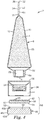
- the tail portion 6c includes a linear edge 32 that forms a blade for smoothing the flowable material 4 after it has been dispensed from the container 2. As shown most clearly in FIGS. 3 and 4 , the terminal end 26 of the tail portion 6c tapers to a point to facilitate the use of the edge 32 as a putty knife.
- the container 2 includes a cap member 34 configured to removably connect with the neck portion 6c, and thereby selectively close the opening 8 in the neck portion 6c. More particularly, the cap member 34 includes a first end 36 having inner threads 38 that cooperate with outer threads 40 provided on the neck portion 6c for threadably securing the cap member 34 to the neck portion 6c. The cap member 34 further includes a second end 42 containing a recessed storage compartment 44.
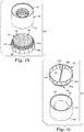
- the container 2 includes an abrasive assembly 56 removably secured to the cap member 34.
- the abrasive assembly includes a top or lid 46 and an abrasive element 58 secured to the lid 46.
- abrasive element 58 is adjacent to cap member 34 and no lid is present.
- the abrasive element 58 may be a coated abrasive, such as sandpaper or a foam backed abrasive, including abrasive particles 66, or abrasive particles may be provided directly on the lid 46.
- the abrasive element 58 is a foam backed abrasive including a foam substrate 60 having first and second opposed major surfaces 62, 64.
- the first major surface 62 is adhesive for bonding the abrasive element 58 to the lid 46, and the second major surface 64 is provided with abrading material.
- the abrading material may be any conventional abrading material such as garnet, aluminum oxide or silicon carbide, which may have a grit size ranging from, for example, 80 to 600.
- the lid 46 includes a base wall 46a having opposed first 48 and second 50 major surfaces, a first annular side wall 46b extending in a first direction away from the base wall first major surface 48, thereby defining a first cavity 52, and a second annular side wall 46c extending in a second direction away from the base wall second major surface 50, thereby defining a second cavity 54.
- the first annular side wall 46b is configured to slidably and releasably engage with the storage compartment 44 of the cap member 34, thereby forming a friction fit.
- the abrasive assembly 56 and cap member 34 may be easily and repeatably connected and disconnected, thereby allowing an end user to quickly and easily access the abrasive element, and use the abrasive element to sand the flowable material 4 to a smooth surface after it has been applied to a surface and allowed to dry and harden.
- separable connections such as a threaded connection or a snap fit connection, may also be used to separably connect the abrasive assembly 56 and cap member 34.
- the abrasive element 58 is arranged in the first cavity 52, and the second cavity 54 includes an optional wall portion 46d.
- the wall 46d may serve as a handle, thereby allowing an end user to more easily sand in tight spaces, such as along adjoining walls that meet at a 90 degree angle.
- the container 2 is opened by removing the cap member 34 along with any moisture seal that may be covering the opening 8.
- the mid portion 6b of the body member 6 is then manually squeezed by the user to dispense the desired amount of flowable material 4 from the container 2 directly onto the damaged surface.
- the cap member 34 is then re-secured to the container 2, and the user can use the tail potion 6c to spread and evenly apply the flowable material 4 to the surface.
- the flowable material is then allowed to dry and harden.
- the sanding assembly 56 can be separated from the cap member 34, and the end user can use the abrasive element 58 to sand the flowable material 4 to produce a smooth finish.
- the smooth repaired surface can then be painted or otherwise finished in the desired manner.
Landscapes
- Engineering & Computer Science (AREA)
- Mechanical Engineering (AREA)
- Containers And Packaging Bodies Having A Special Means To Remove Contents (AREA)
- Coating Apparatus (AREA)
- Closures For Containers (AREA)
- Tubes (AREA)
Applications Claiming Priority (2)
| Application Number | Priority Date | Filing Date | Title |
|---|---|---|---|
| US201461937875P | 2014-02-10 | 2014-02-10 | |
| PCT/US2015/013775 WO2015119853A1 (en) | 2014-02-10 | 2015-01-30 | Multipurpose dispenser for spreadable wall repair compound |
Publications (3)
| Publication Number | Publication Date |
|---|---|
| EP3105135A1 EP3105135A1 (en) | 2016-12-21 |
| EP3105135A4 EP3105135A4 (en) | 2017-11-15 |
| EP3105135B1 true EP3105135B1 (en) | 2019-12-25 |
Family
ID=53778349
Family Applications (1)
| Application Number | Title | Priority Date | Filing Date |
|---|---|---|---|
| EP15746924.8A Active EP3105135B1 (en) | 2014-02-10 | 2015-01-30 | Multipurpose dispenser for spreadable wall repair compound |
Country Status (9)
| Country | Link |
|---|---|
| US (1) | US9896242B2 (https=) |
| EP (1) | EP3105135B1 (https=) |
| JP (1) | JP2017505742A (https=) |
| KR (1) | KR20160122186A (https=) |
| CN (1) | CN105992740B (https=) |
| AU (1) | AU2015214507B2 (https=) |
| CA (1) | CA2939249A1 (https=) |
| MX (1) | MX2016010062A (https=) |
| WO (1) | WO2015119853A1 (https=) |
Families Citing this family (2)
| Publication number | Priority date | Publication date | Assignee | Title |
|---|---|---|---|---|
| JP6922523B2 (ja) * | 2017-07-28 | 2021-08-18 | コクヨ株式会社 | 塗布製品 |
| US11517934B2 (en) | 2019-02-11 | 2022-12-06 | Ryan King | Surface repair tool |
Family Cites Families (29)
| Publication number | Priority date | Publication date | Assignee | Title |
|---|---|---|---|---|
| GB124343A (en) | 1918-06-20 | 1919-03-27 | Ignatius Knaster | Improvements relating to Collapsible Containers for Adhesives or like Solutions and Semi-liquids. |
| US1598811A (en) | 1925-10-17 | 1926-09-07 | Joseph L Ferrin | Cleaning tool |
| US2770826A (en) | 1954-09-28 | 1956-11-20 | Delmar A Christensen | Self-contained window, etc., cleaning implement |
| US3070823A (en) | 1960-02-09 | 1963-01-01 | Johnsie M Heinig | Fountain-type power lawn mower scraper |
| US3121906A (en) * | 1962-05-29 | 1964-02-25 | Jerclaydon Inc | Squeezable tube dispenser |
| US4674903A (en) * | 1985-05-28 | 1987-06-23 | Chen Teng Mo | Fountain facial cleansing sponge head device |
| DE3519321A1 (de) | 1985-05-30 | 1986-12-04 | Erwin 8602 Burgebrach Albrecht | Spachteltube |
| USD326019S (en) | 1987-09-23 | 1992-05-12 | Masco Corporation Of Indiana | Combined brush and scraper attachment for a faucet spray handle |
| US4964538A (en) | 1988-07-20 | 1990-10-23 | Colgate-Palmolive Company | Package for flowable material |
| US4955747A (en) | 1989-11-27 | 1990-09-11 | Tarver Matthew A | Applicator and polishing device |
| FR2663611B1 (fr) | 1990-06-26 | 1992-10-09 | Rg Plastiques | Dispositif pour conditionner et appliquer un produit contenu dans un tube souple et etanche. |
| USD338298S (en) | 1991-02-25 | 1993-08-10 | Grim Sr Robert D | Combined ice scraper and liquid dispenser |
| US5577851A (en) | 1993-02-24 | 1996-11-26 | Painter's Products Inc. | Tube dispenser with sponge applicator |
| US5788104A (en) | 1993-08-13 | 1998-08-04 | Dap Products Inc. | Combination cap and material tooling device |
| USD356259S (en) | 1993-08-13 | 1995-03-14 | DAP Products, Inc. | Combined cap and material applicator |
| US5638990A (en) | 1995-05-01 | 1997-06-17 | Kastberg; David J. | Squeezable container with spreading knife |
| AU6150396A (en) * | 1995-06-07 | 1996-12-30 | Richard L. Owens | Article for applying and spreading viscous material and meth od thereof |
| WO1997006070A1 (en) | 1995-08-09 | 1997-02-20 | Laporte Construction Chemicals North America, Inc. | Improved applicator-container |
| US5803639A (en) | 1996-04-01 | 1998-09-08 | Graphic Controls Corporation | Apparatus for removing medical adhesive devices from skin |
| US7189022B1 (en) | 2001-08-10 | 2007-03-13 | Homax Products, Inc. | Tube with resilient applicator and scraper for dispensing texture materials |
| US8839538B2 (en) | 2001-11-02 | 2014-09-23 | Quality Assured Enterprises, Inc. | Tube container with an integral accessory panel |
| ES2352034T3 (es) | 2002-07-31 | 2011-02-15 | Momentive Performance Materials Inc. | Distribuidor de fluido viscoso. |
| US6767151B1 (en) | 2003-04-22 | 2004-07-27 | Richard L. Owens | Dispenser/spreader article for spackling and paste |
| WO2005039991A2 (en) * | 2003-10-23 | 2005-05-06 | Platinum Innovations, Inc | Dispenser cap and dispenser |
| US20050217034A1 (en) | 2004-04-01 | 2005-10-06 | Henkel Consumer Adhesives, Inc. | Spackling kit and tool |
| ITMI20050053U1 (it) * | 2005-02-22 | 2006-08-23 | Reggiani Fulvio | Tubetto erogatore particolarmente per prodotti smacchiatori e cosmetici in genere |
| US7563048B2 (en) * | 2005-06-16 | 2009-07-21 | Platinum Innovations, Inc. | Twist-open dispenser with applicator & method of applying skin care products & method of merchandising paint |
| CA2641496A1 (en) | 2007-10-23 | 2009-04-23 | Jig-A-World Inc. | Combination cap and material tooling device |
| US20160122088A1 (en) | 2013-06-06 | 2016-05-05 | Michael Jamison | An Applicator |
-
2015
- 2015-01-30 WO PCT/US2015/013775 patent/WO2015119853A1/en not_active Ceased
- 2015-01-30 AU AU2015214507A patent/AU2015214507B2/en not_active Ceased
- 2015-01-30 EP EP15746924.8A patent/EP3105135B1/en active Active
- 2015-01-30 CN CN201580007837.1A patent/CN105992740B/zh not_active Expired - Fee Related
- 2015-01-30 KR KR1020167024733A patent/KR20160122186A/ko not_active Withdrawn
- 2015-01-30 CA CA2939249A patent/CA2939249A1/en not_active Abandoned
- 2015-01-30 JP JP2016568798A patent/JP2017505742A/ja active Pending
- 2015-01-30 MX MX2016010062A patent/MX2016010062A/es unknown
- 2015-01-30 US US15/114,863 patent/US9896242B2/en active Active
Non-Patent Citations (1)
| Title |
|---|
| None * |
Also Published As
| Publication number | Publication date |
|---|---|
| US9896242B2 (en) | 2018-02-20 |
| CN105992740A (zh) | 2016-10-05 |
| AU2015214507A1 (en) | 2016-08-25 |
| WO2015119853A1 (en) | 2015-08-13 |
| AU2015214507B2 (en) | 2017-12-07 |
| MX2016010062A (es) | 2016-10-07 |
| JP2017505742A (ja) | 2017-02-23 |
| EP3105135A4 (en) | 2017-11-15 |
| US20170233146A1 (en) | 2017-08-17 |
| CN105992740B (zh) | 2019-08-02 |
| EP3105135A1 (en) | 2016-12-21 |
| KR20160122186A (ko) | 2016-10-21 |
| CA2939249A1 (en) | 2015-08-13 |
Similar Documents
| Publication | Publication Date | Title |
|---|---|---|
| US5605259A (en) | Method and apparatus for covering irregularities in a wall surface | |
| JP6105591B2 (ja) | 使用者の唇に化粧品を塗布するためのアプリケータ及び関連する塗布方法 | |
| US8967895B2 (en) | Application device for products | |
| US20160157580A1 (en) | Deodorant dispenser and refill cartridge therefor | |
| US10117496B2 (en) | Dropper and cosmetics container having the same | |
| JPH09290843A (ja) | 粘稠物質用分配装置 | |
| US2197579A (en) | Applicator | |
| PL1639912T3 (pl) | Aplikator dla kosmetyku do ust | |
| US20220022624A1 (en) | Apparatus and method for dispensing fluid | |
| US5800144A (en) | Applicator container | |
| EP3105135B1 (en) | Multipurpose dispenser for spreadable wall repair compound | |
| CN103096863B (zh) | 一次性敷料器 | |
| US6821041B1 (en) | Surf wax refillable push-up stick with comb/scraper cap | |
| CA2383006C (en) | Drywall compound dispensing device | |
| KR102037580B1 (ko) | 튜브형 화장품 용기 및 이에 적용되는 캡 | |
| JP2012012056A (ja) | 塗布容器 | |
| EP3982785B1 (en) | A hair oil applicator | |
| US10837186B2 (en) | Patching compound dispenser-applicator | |
| GB2534278A (en) | Nozzle for sealant cartridge | |
| EP3488729A1 (en) | A lid for a flexible or rigid container used for delivering viscous newtonian or non-newtonian fluids | |
| WO2024050642A1 (en) | Apparatus for applying flowable substance from container to surface | |
| CN203958968U (zh) | 可循环使用的膠粘剂涂附装置 | |
| JP2005289489A (ja) | 接着剤注出用容器 | |
| KR20200077687A (ko) | 이종 도포구가 구비된 화장품 용기 |
Legal Events
| Date | Code | Title | Description |
|---|---|---|---|
| PUAI | Public reference made under article 153(3) epc to a published international application that has entered the european phase |
Free format text: ORIGINAL CODE: 0009012 |
|
| STAA | Information on the status of an ep patent application or granted ep patent |
Free format text: STATUS: REQUEST FOR EXAMINATION WAS MADE |
|
| 17P | Request for examination filed |
Effective date: 20160804 |
|
| AK | Designated contracting states |
Kind code of ref document: A1 Designated state(s): AL AT BE BG CH CY CZ DE DK EE ES FI FR GB GR HR HU IE IS IT LI LT LU LV MC MK MT NL NO PL PT RO RS SE SI SK SM TR |
|
| AX | Request for extension of the european patent |
Extension state: BA ME |
|
| DAX | Request for extension of the european patent (deleted) | ||
| A4 | Supplementary search report drawn up and despatched |
Effective date: 20171017 |
|
| RIC1 | Information provided on ipc code assigned before grant |
Ipc: B65D 35/36 20060101AFI20171011BHEP Ipc: B65D 51/28 20060101ALI20171011BHEP |
|
| STAA | Information on the status of an ep patent application or granted ep patent |
Free format text: STATUS: EXAMINATION IS IN PROGRESS |
|
| 17Q | First examination report despatched |
Effective date: 20181016 |
|
| GRAP | Despatch of communication of intention to grant a patent |
Free format text: ORIGINAL CODE: EPIDOSNIGR1 |
|
| STAA | Information on the status of an ep patent application or granted ep patent |
Free format text: STATUS: GRANT OF PATENT IS INTENDED |
|
| INTG | Intention to grant announced |
Effective date: 20190801 |
|
| GRAS | Grant fee paid |
Free format text: ORIGINAL CODE: EPIDOSNIGR3 |
|
| GRAA | (expected) grant |
Free format text: ORIGINAL CODE: 0009210 |
|
| STAA | Information on the status of an ep patent application or granted ep patent |
Free format text: STATUS: THE PATENT HAS BEEN GRANTED |
|
| AK | Designated contracting states |
Kind code of ref document: B1 Designated state(s): AL AT BE BG CH CY CZ DE DK EE ES FI FR GB GR HR HU IE IS IT LI LT LU LV MC MK MT NL NO PL PT RO RS SE SI SK SM TR |
|
| REG | Reference to a national code |
Ref country code: GB Ref legal event code: FG4D |
|
| REG | Reference to a national code |
Ref country code: CH Ref legal event code: EP |
|
| REG | Reference to a national code |
Ref country code: AT Ref legal event code: REF Ref document number: 1216872 Country of ref document: AT Kind code of ref document: T Effective date: 20200115 |
|
| REG | Reference to a national code |
Ref country code: DE Ref legal event code: R096 Ref document number: 602015044284 Country of ref document: DE |
|
| REG | Reference to a national code |
Ref country code: IE Ref legal event code: FG4D |
|
| REG | Reference to a national code |
Ref country code: NL Ref legal event code: MP Effective date: 20191225 |
|
| PG25 | Lapsed in a contracting state [announced via postgrant information from national office to epo] |
Ref country code: NO Free format text: LAPSE BECAUSE OF FAILURE TO SUBMIT A TRANSLATION OF THE DESCRIPTION OR TO PAY THE FEE WITHIN THE PRESCRIBED TIME-LIMIT Effective date: 20200325 Ref country code: GR Free format text: LAPSE BECAUSE OF FAILURE TO SUBMIT A TRANSLATION OF THE DESCRIPTION OR TO PAY THE FEE WITHIN THE PRESCRIBED TIME-LIMIT Effective date: 20200326 Ref country code: LT Free format text: LAPSE BECAUSE OF FAILURE TO SUBMIT A TRANSLATION OF THE DESCRIPTION OR TO PAY THE FEE WITHIN THE PRESCRIBED TIME-LIMIT Effective date: 20191225 Ref country code: SE Free format text: LAPSE BECAUSE OF FAILURE TO SUBMIT A TRANSLATION OF THE DESCRIPTION OR TO PAY THE FEE WITHIN THE PRESCRIBED TIME-LIMIT Effective date: 20191225 Ref country code: LV Free format text: LAPSE BECAUSE OF FAILURE TO SUBMIT A TRANSLATION OF THE DESCRIPTION OR TO PAY THE FEE WITHIN THE PRESCRIBED TIME-LIMIT Effective date: 20191225 Ref country code: FI Free format text: LAPSE BECAUSE OF FAILURE TO SUBMIT A TRANSLATION OF THE DESCRIPTION OR TO PAY THE FEE WITHIN THE PRESCRIBED TIME-LIMIT Effective date: 20191225 Ref country code: BG Free format text: LAPSE BECAUSE OF FAILURE TO SUBMIT A TRANSLATION OF THE DESCRIPTION OR TO PAY THE FEE WITHIN THE PRESCRIBED TIME-LIMIT Effective date: 20200325 |
|
| REG | Reference to a national code |
Ref country code: LT Ref legal event code: MG4D |
|
| PG25 | Lapsed in a contracting state [announced via postgrant information from national office to epo] |
Ref country code: RS Free format text: LAPSE BECAUSE OF FAILURE TO SUBMIT A TRANSLATION OF THE DESCRIPTION OR TO PAY THE FEE WITHIN THE PRESCRIBED TIME-LIMIT Effective date: 20191225 Ref country code: HR Free format text: LAPSE BECAUSE OF FAILURE TO SUBMIT A TRANSLATION OF THE DESCRIPTION OR TO PAY THE FEE WITHIN THE PRESCRIBED TIME-LIMIT Effective date: 20191225 |
|
| PG25 | Lapsed in a contracting state [announced via postgrant information from national office to epo] |
Ref country code: AL Free format text: LAPSE BECAUSE OF FAILURE TO SUBMIT A TRANSLATION OF THE DESCRIPTION OR TO PAY THE FEE WITHIN THE PRESCRIBED TIME-LIMIT Effective date: 20191225 |
|
| PG25 | Lapsed in a contracting state [announced via postgrant information from national office to epo] |
Ref country code: EE Free format text: LAPSE BECAUSE OF FAILURE TO SUBMIT A TRANSLATION OF THE DESCRIPTION OR TO PAY THE FEE WITHIN THE PRESCRIBED TIME-LIMIT Effective date: 20191225 Ref country code: PT Free format text: LAPSE BECAUSE OF FAILURE TO SUBMIT A TRANSLATION OF THE DESCRIPTION OR TO PAY THE FEE WITHIN THE PRESCRIBED TIME-LIMIT Effective date: 20200520 Ref country code: NL Free format text: LAPSE BECAUSE OF FAILURE TO SUBMIT A TRANSLATION OF THE DESCRIPTION OR TO PAY THE FEE WITHIN THE PRESCRIBED TIME-LIMIT Effective date: 20191225 Ref country code: RO Free format text: LAPSE BECAUSE OF FAILURE TO SUBMIT A TRANSLATION OF THE DESCRIPTION OR TO PAY THE FEE WITHIN THE PRESCRIBED TIME-LIMIT Effective date: 20191225 Ref country code: CZ Free format text: LAPSE BECAUSE OF FAILURE TO SUBMIT A TRANSLATION OF THE DESCRIPTION OR TO PAY THE FEE WITHIN THE PRESCRIBED TIME-LIMIT Effective date: 20191225 |
|
| REG | Reference to a national code |
Ref country code: DE Ref legal event code: R119 Ref document number: 602015044284 Country of ref document: DE |
|
| PG25 | Lapsed in a contracting state [announced via postgrant information from national office to epo] |
Ref country code: SM Free format text: LAPSE BECAUSE OF FAILURE TO SUBMIT A TRANSLATION OF THE DESCRIPTION OR TO PAY THE FEE WITHIN THE PRESCRIBED TIME-LIMIT Effective date: 20191225 Ref country code: SK Free format text: LAPSE BECAUSE OF FAILURE TO SUBMIT A TRANSLATION OF THE DESCRIPTION OR TO PAY THE FEE WITHIN THE PRESCRIBED TIME-LIMIT Effective date: 20191225 Ref country code: IS Free format text: LAPSE BECAUSE OF FAILURE TO SUBMIT A TRANSLATION OF THE DESCRIPTION OR TO PAY THE FEE WITHIN THE PRESCRIBED TIME-LIMIT Effective date: 20200425 |
|
| REG | Reference to a national code |
Ref country code: CH Ref legal event code: PL |
|
| PG25 | Lapsed in a contracting state [announced via postgrant information from national office to epo] |
Ref country code: MC Free format text: LAPSE BECAUSE OF FAILURE TO SUBMIT A TRANSLATION OF THE DESCRIPTION OR TO PAY THE FEE WITHIN THE PRESCRIBED TIME-LIMIT Effective date: 20191225 |
|
| REG | Reference to a national code |
Ref country code: BE Ref legal event code: MM Effective date: 20200131 |
|
| PG25 | Lapsed in a contracting state [announced via postgrant information from national office to epo] |
Ref country code: DE Free format text: LAPSE BECAUSE OF NON-PAYMENT OF DUE FEES Effective date: 20200801 Ref country code: DK Free format text: LAPSE BECAUSE OF FAILURE TO SUBMIT A TRANSLATION OF THE DESCRIPTION OR TO PAY THE FEE WITHIN THE PRESCRIBED TIME-LIMIT Effective date: 20191225 Ref country code: ES Free format text: LAPSE BECAUSE OF FAILURE TO SUBMIT A TRANSLATION OF THE DESCRIPTION OR TO PAY THE FEE WITHIN THE PRESCRIBED TIME-LIMIT Effective date: 20191225 Ref country code: LU Free format text: LAPSE BECAUSE OF NON-PAYMENT OF DUE FEES Effective date: 20200130 |
|
| PLBE | No opposition filed within time limit |
Free format text: ORIGINAL CODE: 0009261 |
|
| STAA | Information on the status of an ep patent application or granted ep patent |
Free format text: STATUS: NO OPPOSITION FILED WITHIN TIME LIMIT |
|
| REG | Reference to a national code |
Ref country code: AT Ref legal event code: MK05 Ref document number: 1216872 Country of ref document: AT Kind code of ref document: T Effective date: 20191225 |
|
| PG25 | Lapsed in a contracting state [announced via postgrant information from national office to epo] |
Ref country code: BE Free format text: LAPSE BECAUSE OF NON-PAYMENT OF DUE FEES Effective date: 20200131 Ref country code: SI Free format text: LAPSE BECAUSE OF FAILURE TO SUBMIT A TRANSLATION OF THE DESCRIPTION OR TO PAY THE FEE WITHIN THE PRESCRIBED TIME-LIMIT Effective date: 20191225 Ref country code: CH Free format text: LAPSE BECAUSE OF NON-PAYMENT OF DUE FEES Effective date: 20200131 Ref country code: LI Free format text: LAPSE BECAUSE OF NON-PAYMENT OF DUE FEES Effective date: 20200131 |
|
| 26N | No opposition filed |
Effective date: 20200928 |
|
| PG25 | Lapsed in a contracting state [announced via postgrant information from national office to epo] |
Ref country code: AT Free format text: LAPSE BECAUSE OF FAILURE TO SUBMIT A TRANSLATION OF THE DESCRIPTION OR TO PAY THE FEE WITHIN THE PRESCRIBED TIME-LIMIT Effective date: 20191225 Ref country code: IE Free format text: LAPSE BECAUSE OF NON-PAYMENT OF DUE FEES Effective date: 20200130 Ref country code: IT Free format text: LAPSE BECAUSE OF FAILURE TO SUBMIT A TRANSLATION OF THE DESCRIPTION OR TO PAY THE FEE WITHIN THE PRESCRIBED TIME-LIMIT Effective date: 20191225 |
|
| PG25 | Lapsed in a contracting state [announced via postgrant information from national office to epo] |
Ref country code: PL Free format text: LAPSE BECAUSE OF FAILURE TO SUBMIT A TRANSLATION OF THE DESCRIPTION OR TO PAY THE FEE WITHIN THE PRESCRIBED TIME-LIMIT Effective date: 20191225 |
|
| GBPC | Gb: european patent ceased through non-payment of renewal fee |
Effective date: 20200325 |
|
| PG25 | Lapsed in a contracting state [announced via postgrant information from national office to epo] |
Ref country code: GB Free format text: LAPSE BECAUSE OF NON-PAYMENT OF DUE FEES Effective date: 20200325 |
|
| PGFP | Annual fee paid to national office [announced via postgrant information from national office to epo] |
Ref country code: FR Payment date: 20211215 Year of fee payment: 8 |
|
| PG25 | Lapsed in a contracting state [announced via postgrant information from national office to epo] |
Ref country code: TR Free format text: LAPSE BECAUSE OF FAILURE TO SUBMIT A TRANSLATION OF THE DESCRIPTION OR TO PAY THE FEE WITHIN THE PRESCRIBED TIME-LIMIT Effective date: 20191225 Ref country code: MT Free format text: LAPSE BECAUSE OF FAILURE TO SUBMIT A TRANSLATION OF THE DESCRIPTION OR TO PAY THE FEE WITHIN THE PRESCRIBED TIME-LIMIT Effective date: 20191225 Ref country code: CY Free format text: LAPSE BECAUSE OF FAILURE TO SUBMIT A TRANSLATION OF THE DESCRIPTION OR TO PAY THE FEE WITHIN THE PRESCRIBED TIME-LIMIT Effective date: 20191225 |
|
| PG25 | Lapsed in a contracting state [announced via postgrant information from national office to epo] |
Ref country code: MK Free format text: LAPSE BECAUSE OF FAILURE TO SUBMIT A TRANSLATION OF THE DESCRIPTION OR TO PAY THE FEE WITHIN THE PRESCRIBED TIME-LIMIT Effective date: 20191225 |
|
| PG25 | Lapsed in a contracting state [announced via postgrant information from national office to epo] |
Ref country code: FR Free format text: LAPSE BECAUSE OF NON-PAYMENT OF DUE FEES Effective date: 20230131 |