EP3105045B1 - Pressschneckenseparator - Google Patents
Pressschneckenseparator Download PDFInfo
- Publication number
- EP3105045B1 EP3105045B1 EP15703610.4A EP15703610A EP3105045B1 EP 3105045 B1 EP3105045 B1 EP 3105045B1 EP 15703610 A EP15703610 A EP 15703610A EP 3105045 B1 EP3105045 B1 EP 3105045B1
- Authority
- EP
- European Patent Office
- Prior art keywords
- wear ring
- screen
- chamber
- screw
- sieve
- Prior art date
- Legal status (The legal status is an assumption and is not a legal conclusion. Google has not performed a legal analysis and makes no representation as to the accuracy of the status listed.)
- Active
Links
Images


Classifications
-
- B—PERFORMING OPERATIONS; TRANSPORTING
- B30—PRESSES
- B30B—PRESSES IN GENERAL
- B30B9/00—Presses specially adapted for particular purposes
- B30B9/02—Presses specially adapted for particular purposes for squeezing-out liquid from liquid-containing material, e.g. juice from fruits, oil from oil-containing material
- B30B9/12—Presses specially adapted for particular purposes for squeezing-out liquid from liquid-containing material, e.g. juice from fruits, oil from oil-containing material using pressing worms or screws co-operating with a permeable casing
- B30B9/127—Feed means
-
- B—PERFORMING OPERATIONS; TRANSPORTING
- B30—PRESSES
- B30B—PRESSES IN GENERAL
- B30B9/00—Presses specially adapted for particular purposes
- B30B9/02—Presses specially adapted for particular purposes for squeezing-out liquid from liquid-containing material, e.g. juice from fruits, oil from oil-containing material
- B30B9/26—Permeable casings or strainers
Definitions
- the present invention relates to a screw press separator for separating solid components from a slurry containing solid and liquid components.
- Screw press separators are used to squeeze out a pulp.
- the slurry can in particular be liquid manure or waste water.
- the wastewater can come from both municipal and industrial plants, whereby these should always be separated into solid and liquid components.
- a cylindrical screen is usually arranged in the housing of the press screw separators, within which a screw rotates. By means of the screw, the pulp is conveyed through the press screw separator and pressed. The liquid fractions of the pulp pass through the sieve, while a solid plug forms inside the sieve. The solid plug is conveyed to one end of the press screw separator by the rotating screw in order to be discharged there.
- the pamphlet DE10342684 A1 shows a previously known screw press separator.
- this screw press separator according to the preamble of claim 1, several slots are formed at the transition from the housing to the sieve chamber.
- the slots form an angle to the screw rotating above, which promotes the thrust and shear effects.
- the slots are integral elements molded into the housing.
- the object is thus achieved by a screw press separator for separating solid components from a pulp containing solid and liquid components.
- the screw press separator comprises a housing with an inlet chamber and a sieve chamber.
- the inlet chamber merges into the sieve chamber.
- an inlet for the pulp, an outlet for the solid constituents and an outlet for the liquid constituents are formed on the housing.
- a screen in particular a cylindrical screen, is arranged in the screen chamber.
- a screw extends through the inlet chamber and into the screen. The screw can rotate about a longitudinal axis of the sieve. As the screw rotates, the pulp is pressed out along the sieve.
- the screw is preferably driven by a motor, the inlet chamber being located between the motor and the sieve chamber.
- a wear ring is arranged at the transition from the inlet chamber to the sieve chamber.
- the worm extends through this wear ring.
- the wear ring is attached to the housing and can be replaced.
- the wear ring can be attached to the inlet chamber.
- Several cutting edges are formed on the inner circumference of the wear ring. The very narrow gap between the outer edges of the screw threads and these cutting edges leads to a shear effect and thus to a breaking up of long-fiber solids in the pulp. This largely avoids clogging of the sieve.
- the wear ring is attached to the housing in an exchangeable manner and can easily be exchanged after corresponding wear.
- the wear ring is arranged as an axial stop for the sieve.
- a largest diameter of the wear ring is greater than a smallest diameter of the sieve.
- One end face of the screen can thus rest against the wear ring.
- the wear ring according to the invention With its cutting edges, not only serves to break up long-fiber constituents of the pulp but also serves at the same time as an axial stop for the sieve.
- Such an axial stop for the sieve is also subject to increased wear. With only one component, namely the wear ring, two wear-prone parts of the press screw separator, namely the cutting edges and the axial stop, are formed.
- the wear ring has a first length.
- the entire screw has a second length.
- the two lengths are measured in the longitudinal direction of the sieve. It is preferably provided that the first length is a maximum of 10%, preferably a maximum of 5%, of the second length. This ensures that the wear ring according to the invention has a relatively small structure and thus only the component of the press screw separator that is subject to wear is replaced.
- the wear ring and the cutting edges are arranged in front of the sieve and do not extend into the sieve.
- the wear ring is therefore only located in the transition area from the inlet chamber to the sieve chamber and does not extend into the sieve. In this transition area in particular, the cutting edges are necessary, since here the long-fiber components can be processed before they enter the sieve.
- the wear ring is preferably screwed to the housing.
- several screw connections are provided in particular, which extend parallel to the longitudinal axis of the sieve. The screw connection enables the wear ring to be exchanged easily.
- the wear ring is a one-piece, closed ring.
- the cutting edges are an integral part of the closed ring.
- the entire wear ring is a cast component.
- This cast component is fitted into the housing by appropriate machining.
- a wear ring for the press screw separator is also disclosed.
- This wear ring is used in a press screw separator as described above.
- the wear ring as a separate, economically tradable component, is designed to be arranged at the transition area from the inlet chamber to the sieve chamber.
- the wear ring is attached so that it can be replaced.
- Several cutting edges are formed on the inner circumference of the wear ring.
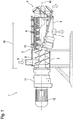
- the press screw separator 1 comprises a housing 2. An inlet chamber 3 and a sieve chamber 4 are formed in the housing 2. The inlet chamber 3 merges into the sieve chamber 4.
- the housing 2 comprises an inlet 5 on the inlet chamber 3. This inlet 5 is used to fill in a slurry.
- An outlet 6 and an outlet 7 are formed on the sieve chamber 4. The outlet 6 is used with a corresponding mechanism for discharging the separated solids in batches. The liquid component separated from the pulp flows out of the housing 2 via the outlet 7.
- a gear 11 is flanged to the housing 2.
- the transmission 11 is in turn driven by a motor 12.
- the inlet chamber 3 is located between the gearbox-motor unit and the sieve chamber 4.
- a screw 9 extends from the gear mechanism 11 through the inlet chamber 3 into the sieve chamber 4.
- a hollow cylindrical sieve 8 is arranged in the sieve chamber 4. Both the sieve 8 and the screw 9 extend along a longitudinal axis 10.
- the pulp to be separated is poured in via the inlet 5.
- This pulp is conveyed by the rotating screw 9 in the direction of the outlet 6.
- a solid plug forms in the area of the outlet 6.
- the corresponding liquid components of the pulp pass through the sieve 8 radially outwards and flow off via the outlet 7.
- a wear ring 13 is located at the transition from the inlet chamber 3 to the sieve chamber 4.
- Fig. 2 shows in detail the design and arrangement of this wear ring 13.
- the wear ring 13 is a one-piece cast and machined machined component.
- a plurality of ribs 14 are formed on the inner circumference of the wear ring 13.
- the wear ring 13 comprises an angular region 15 on its outer circumference.
- the wear ring 13 is fastened in the housing 2 via this angular region 15. It is fastened by means of screw connections 16. By means of these screw connections 16, the wear ring 13 can easily be exchanged.
- Fig. 2 shows Fig. 2 that the diameter of the sieve 8 and the diameter of the wear ring 13 are selected so that the sieve 8 strikes the wear ring 13 in the axial direction.
- the wear ring 13 thus serves as an axial stop for the sieve 8.
- Fig. 3 shows the in Fig. 2 marked section A: A.
- each rib 14 forms two cutting edges 17.
- the cutting edges 17 are thus formed by the ribs 14.
- the cutting edges 17 extend parallel to the longitudinal axis 10.
- the outer edges of the spirals of the worm 9 move over these cutting edges 17 with only a very small distance.
- a corresponding shear load acts on, in particular, long-fiber components in the pulp during the transition from the inlet chamber 3 to the sieve chamber 4.
- a multiplicity of ribs 14, preferably more than 20, is provided.
- the narrow gap between the cutting edges 17 and the outer edges of the spirals of the screw 9 is preferably 0.1 to 0.5 mm.
- Fig. 2 shows a first length 18 of the wear ring 13 measured in the direction of the longitudinal axis 10.
- Fig. 1 shows a second length 19 of the entire screw 9, also measured in the direction of the longitudinal axis 10.
- the comparison of these two lengths 18, 19 shows that the wear ring 13 occupies only a small fraction of the second length 19 of the screw 9 in the direction of the longitudinal axis 10.
- the first length 18 is a maximum of 10%, preferably a maximum of 5%, of the second length 19.
- the wear ring 13 does not extend into the sieve 8. Rather, the wear ring 13 ends in front of the sieve 18 and can thus also form a stop for the sieve 18.
Landscapes
- Engineering & Computer Science (AREA)
- Mechanical Engineering (AREA)
- Paper (AREA)
- Treatment Of Sludge (AREA)
- Filtration Of Liquid (AREA)
Priority Applications (1)
| Application Number | Priority Date | Filing Date | Title |
|---|---|---|---|
| PL15703610T PL3105045T3 (pl) | 2014-02-13 | 2015-02-11 | Ślimakowy separator tłoczący |
Applications Claiming Priority (2)
| Application Number | Priority Date | Filing Date | Title |
|---|---|---|---|
| DE201420001409 DE202014001409U1 (de) | 2014-02-13 | 2014-02-13 | Pressschneckenseparator und Verschleißring |
| PCT/EP2015/052828 WO2015121280A1 (de) | 2014-02-13 | 2015-02-11 | PRESSSCHNECKENSEPARATOR UND VERSCHLEIßRING |
Publications (2)
| Publication Number | Publication Date |
|---|---|
| EP3105045A1 EP3105045A1 (de) | 2016-12-21 |
| EP3105045B1 true EP3105045B1 (de) | 2021-04-28 |
Family
ID=50276754
Family Applications (1)
| Application Number | Title | Priority Date | Filing Date |
|---|---|---|---|
| EP15703610.4A Active EP3105045B1 (de) | 2014-02-13 | 2015-02-11 | Pressschneckenseparator |
Country Status (7)
| Country | Link |
|---|---|
| EP (1) | EP3105045B1 (pl) |
| DE (1) | DE202014001409U1 (pl) |
| DK (1) | DK3105045T3 (pl) |
| ES (1) | ES2882120T3 (pl) |
| HU (1) | HUE055645T2 (pl) |
| PL (1) | PL3105045T3 (pl) |
| WO (1) | WO2015121280A1 (pl) |
Families Citing this family (1)
| Publication number | Priority date | Publication date | Assignee | Title |
|---|---|---|---|---|
| DE102016204375B4 (de) * | 2016-03-16 | 2026-02-05 | Röhren- Und Pumpenwerk Bauer Ges.M.B.H. | Anordnung und Verfahren zur Pasteurisierung und anschließenden Feststoffabscheidung einer Trübe |
Family Cites Families (10)
| Publication number | Priority date | Publication date | Assignee | Title |
|---|---|---|---|---|
| GB571019A (en) * | 1943-06-01 | 1945-08-02 | Bibby & Sons Ltd J | Improvements in or relating to machines for expressing liquids from solids |
| DE2351328A1 (de) * | 1973-10-12 | 1975-04-24 | Ver Foerderung Inst Kunststoff | Verfahren und einrichtung zum verarbeiten von zuvor unzerkleinerten thermoplastischen kunststoffabfaellen (altmaterial) in einschnecken-extrudern |
| DE4011248A1 (de) * | 1990-04-06 | 1991-10-10 | Poettinger Alois Landmasch | Schneckenpresse |
| DE10342684A1 (de) | 2003-09-16 | 2005-04-28 | Fan Separator Gmbh | Schneid- und Schutzeinrichtung für Pressschneckenseparatoren |
| DE102006002016A1 (de) * | 2006-01-13 | 2007-07-19 | Andreas Kufferath Gmbh & Co. Kg | Schneckenwelle für eine Schneckenpresse |
| DE202010001758U1 (de) * | 2010-02-02 | 2011-06-09 | UTS Biogastechnik GmbH, 85399 | Schneckenseparator |
| DE202010001765U1 (de) * | 2010-02-02 | 2011-06-09 | UTS Biogastechnik GmbH, 85399 | Schneckenseparator |
| EP2561981A3 (en) * | 2011-08-26 | 2013-12-25 | Thöni Industriebetriebe GmbH | Screw conveyor |
| DE102011086615A1 (de) * | 2011-11-18 | 2013-05-23 | Voith Patent Gmbh | Schneckenpresse I |
| DE202013003874U1 (de) * | 2013-04-24 | 2013-05-15 | Röhren- Und Pumpenwerk Bauer Ges.M.B.H. | Pressschneckenseparator |
-
2014
- 2014-02-13 DE DE201420001409 patent/DE202014001409U1/de not_active Expired - Lifetime
-
2015
- 2015-02-11 DK DK15703610.4T patent/DK3105045T3/da active
- 2015-02-11 WO PCT/EP2015/052828 patent/WO2015121280A1/de not_active Ceased
- 2015-02-11 ES ES15703610T patent/ES2882120T3/es active Active
- 2015-02-11 HU HUE15703610A patent/HUE055645T2/hu unknown
- 2015-02-11 EP EP15703610.4A patent/EP3105045B1/de active Active
- 2015-02-11 PL PL15703610T patent/PL3105045T3/pl unknown
Non-Patent Citations (1)
| Title |
|---|
| None * |
Also Published As
| Publication number | Publication date |
|---|---|
| HUE055645T2 (hu) | 2021-12-28 |
| DK3105045T3 (da) | 2021-08-02 |
| EP3105045A1 (de) | 2016-12-21 |
| WO2015121280A1 (de) | 2015-08-20 |
| ES2882120T3 (es) | 2021-12-01 |
| PL3105045T3 (pl) | 2021-11-22 |
| DE202014001409U1 (de) | 2014-02-25 |
Similar Documents
| Publication | Publication Date | Title |
|---|---|---|
| EP1943022B1 (de) | Rührwerksmühle | |
| EP2938418B1 (de) | Pressschneckenseparator | |
| EP2677178B1 (de) | Pumpe | |
| DE69304281T2 (de) | Gerät zum trennen von feststoffen und flüssigkeiten | |
| EP3330068B1 (de) | Vorrichtung zum entwässern von schüttfähigem oder fliessfähigem aufgabegut | |
| WO2010108932A1 (de) | Schneidvorrichtung | |
| EP2091657B1 (de) | Zentrifuge, insbesondere separator, mit feststoff-austrittsdüsen | |
| DE2313403A1 (de) | Axial-stroemungsmaschine | |
| EP2754552B1 (de) | Pressschneckenseparator und Verfahren zum Betrieb des Pressschneckenseparators | |
| DE102005061461A1 (de) | Vollmantel-Schneckenzentrifuge | |
| EP2707629B1 (de) | Vorrichtung zum abdichten eines pumpraums einer drehkolbenpumpe, sowie drehkolbenpumpe mit selbiger | |
| EP3105045B1 (de) | Pressschneckenseparator | |
| EP3427937A1 (de) | Schnecke eines pressschneckenseparators | |
| EP0623712A2 (de) | Vorrichtung zum Entfernen von Abscheidegut aus einer Flüssigkeit | |
| DE2757746A1 (de) | Vorrichtung zum aufbereiten einer suspension | |
| EP1949966B1 (de) | Vollmantel-Schneckenzentrifuge mit einer Stauscheibe | |
| DE202012011864U1 (de) | Pressschneckenseparator | |
| DE102015212653A1 (de) | Haushaltsgerät | |
| AT526355B1 (de) | Pressschneckenseparator mit modifizierter Pressschnecke | |
| DE102013000561B3 (de) | Pressschneckenseparator und Siebanordnung | |
| EP3094479B1 (de) | Pressschnecke für einen pressschneckenseparator | |
| AT525727B1 (de) | Pressschneckenseparator | |
| LU102840B1 (de) | Schneidring für mit Feststoff belastete Flüssigkeit einer Pumpe | |
| EP3347521B1 (de) | Rotierende trommel | |
| DE1912501U (de) | Vorrichtung zur beseitigung von abfaellen. |
Legal Events
| Date | Code | Title | Description |
|---|---|---|---|
| PUAI | Public reference made under article 153(3) epc to a published international application that has entered the european phase |
Free format text: ORIGINAL CODE: 0009012 |
|
| STAA | Information on the status of an ep patent application or granted ep patent |
Free format text: STATUS: REQUEST FOR EXAMINATION WAS MADE |
|
| 17P | Request for examination filed |
Effective date: 20160711 |
|
| AK | Designated contracting states |
Kind code of ref document: A1 Designated state(s): AL AT BE BG CH CY CZ DE DK EE ES FI FR GB GR HR HU IE IS IT LI LT LU LV MC MK MT NL NO PL PT RO RS SE SI SK SM TR |
|
| AX | Request for extension of the european patent |
Extension state: BA ME |
|
| DAX | Request for extension of the european patent (deleted) | ||
| STAA | Information on the status of an ep patent application or granted ep patent |
Free format text: STATUS: EXAMINATION IS IN PROGRESS |
|
| 17Q | First examination report despatched |
Effective date: 20200211 |
|
| GRAP | Despatch of communication of intention to grant a patent |
Free format text: ORIGINAL CODE: EPIDOSNIGR1 |
|
| STAA | Information on the status of an ep patent application or granted ep patent |
Free format text: STATUS: GRANT OF PATENT IS INTENDED |
|
| GRAS | Grant fee paid |
Free format text: ORIGINAL CODE: EPIDOSNIGR3 |
|
| INTG | Intention to grant announced |
Effective date: 20210225 |
|
| GRAA | (expected) grant |
Free format text: ORIGINAL CODE: 0009210 |
|
| STAA | Information on the status of an ep patent application or granted ep patent |
Free format text: STATUS: THE PATENT HAS BEEN GRANTED |
|
| AK | Designated contracting states |
Kind code of ref document: B1 Designated state(s): AL AT BE BG CH CY CZ DE DK EE ES FI FR GB GR HR HU IE IS IT LI LT LU LV MC MK MT NL NO PL PT RO RS SE SI SK SM TR |
|
| REG | Reference to a national code |
Ref country code: GB Ref legal event code: FG4D Free format text: NOT ENGLISH |
|
| REG | Reference to a national code |
Ref country code: CH Ref legal event code: EP |
|
| REG | Reference to a national code |
Ref country code: AT Ref legal event code: REF Ref document number: 1386632 Country of ref document: AT Kind code of ref document: T Effective date: 20210515 |
|
| REG | Reference to a national code |
Ref country code: DE Ref legal event code: R096 Ref document number: 502015014624 Country of ref document: DE |
|
| REG | Reference to a national code |
Ref country code: IE Ref legal event code: FG4D Free format text: LANGUAGE OF EP DOCUMENT: GERMAN |
|
| REG | Reference to a national code |
Ref country code: DK Ref legal event code: T3 Effective date: 20210727 |
|
| REG | Reference to a national code |
Ref country code: NL Ref legal event code: FP |
|
| REG | Reference to a national code |
Ref country code: RO Ref legal event code: EPE |
|
| REG | Reference to a national code |
Ref country code: LT Ref legal event code: MG9D |
|
| REG | Reference to a national code |
Ref country code: SK Ref legal event code: T3 Ref document number: E 38041 Country of ref document: SK |
|
| PG25 | Lapsed in a contracting state [announced via postgrant information from national office to epo] |
Ref country code: FI Free format text: LAPSE BECAUSE OF FAILURE TO SUBMIT A TRANSLATION OF THE DESCRIPTION OR TO PAY THE FEE WITHIN THE PRESCRIBED TIME-LIMIT Effective date: 20210428 Ref country code: LT Free format text: LAPSE BECAUSE OF FAILURE TO SUBMIT A TRANSLATION OF THE DESCRIPTION OR TO PAY THE FEE WITHIN THE PRESCRIBED TIME-LIMIT Effective date: 20210428 Ref country code: HR Free format text: LAPSE BECAUSE OF FAILURE TO SUBMIT A TRANSLATION OF THE DESCRIPTION OR TO PAY THE FEE WITHIN THE PRESCRIBED TIME-LIMIT Effective date: 20210428 Ref country code: BG Free format text: LAPSE BECAUSE OF FAILURE TO SUBMIT A TRANSLATION OF THE DESCRIPTION OR TO PAY THE FEE WITHIN THE PRESCRIBED TIME-LIMIT Effective date: 20210728 |
|
| PG25 | Lapsed in a contracting state [announced via postgrant information from national office to epo] |
Ref country code: NO Free format text: LAPSE BECAUSE OF FAILURE TO SUBMIT A TRANSLATION OF THE DESCRIPTION OR TO PAY THE FEE WITHIN THE PRESCRIBED TIME-LIMIT Effective date: 20210728 Ref country code: PT Free format text: LAPSE BECAUSE OF FAILURE TO SUBMIT A TRANSLATION OF THE DESCRIPTION OR TO PAY THE FEE WITHIN THE PRESCRIBED TIME-LIMIT Effective date: 20210830 Ref country code: RS Free format text: LAPSE BECAUSE OF FAILURE TO SUBMIT A TRANSLATION OF THE DESCRIPTION OR TO PAY THE FEE WITHIN THE PRESCRIBED TIME-LIMIT Effective date: 20210428 Ref country code: SE Free format text: LAPSE BECAUSE OF FAILURE TO SUBMIT A TRANSLATION OF THE DESCRIPTION OR TO PAY THE FEE WITHIN THE PRESCRIBED TIME-LIMIT Effective date: 20210428 Ref country code: GR Free format text: LAPSE BECAUSE OF FAILURE TO SUBMIT A TRANSLATION OF THE DESCRIPTION OR TO PAY THE FEE WITHIN THE PRESCRIBED TIME-LIMIT Effective date: 20210729 Ref country code: IS Free format text: LAPSE BECAUSE OF FAILURE TO SUBMIT A TRANSLATION OF THE DESCRIPTION OR TO PAY THE FEE WITHIN THE PRESCRIBED TIME-LIMIT Effective date: 20210828 Ref country code: LV Free format text: LAPSE BECAUSE OF FAILURE TO SUBMIT A TRANSLATION OF THE DESCRIPTION OR TO PAY THE FEE WITHIN THE PRESCRIBED TIME-LIMIT Effective date: 20210428 |
|
| REG | Reference to a national code |
Ref country code: ES Ref legal event code: FG2A Ref document number: 2882120 Country of ref document: ES Kind code of ref document: T3 Effective date: 20211201 |
|
| REG | Reference to a national code |
Ref country code: HU Ref legal event code: AG4A Ref document number: E055645 Country of ref document: HU |
|
| PG25 | Lapsed in a contracting state [announced via postgrant information from national office to epo] |
Ref country code: EE Free format text: LAPSE BECAUSE OF FAILURE TO SUBMIT A TRANSLATION OF THE DESCRIPTION OR TO PAY THE FEE WITHIN THE PRESCRIBED TIME-LIMIT Effective date: 20210428 Ref country code: SM Free format text: LAPSE BECAUSE OF FAILURE TO SUBMIT A TRANSLATION OF THE DESCRIPTION OR TO PAY THE FEE WITHIN THE PRESCRIBED TIME-LIMIT Effective date: 20210428 |
|
| REG | Reference to a national code |
Ref country code: DE Ref legal event code: R097 Ref document number: 502015014624 Country of ref document: DE |
|
| PLBE | No opposition filed within time limit |
Free format text: ORIGINAL CODE: 0009261 |
|
| STAA | Information on the status of an ep patent application or granted ep patent |
Free format text: STATUS: NO OPPOSITION FILED WITHIN TIME LIMIT |
|
| 26N | No opposition filed |
Effective date: 20220131 |
|
| PG25 | Lapsed in a contracting state [announced via postgrant information from national office to epo] |
Ref country code: IS Free format text: LAPSE BECAUSE OF FAILURE TO SUBMIT A TRANSLATION OF THE DESCRIPTION OR TO PAY THE FEE WITHIN THE PRESCRIBED TIME-LIMIT Effective date: 20210828 Ref country code: AL Free format text: LAPSE BECAUSE OF FAILURE TO SUBMIT A TRANSLATION OF THE DESCRIPTION OR TO PAY THE FEE WITHIN THE PRESCRIBED TIME-LIMIT Effective date: 20210428 |
|
| PG25 | Lapsed in a contracting state [announced via postgrant information from national office to epo] |
Ref country code: MC Free format text: LAPSE BECAUSE OF FAILURE TO SUBMIT A TRANSLATION OF THE DESCRIPTION OR TO PAY THE FEE WITHIN THE PRESCRIBED TIME-LIMIT Effective date: 20210428 |
|
| REG | Reference to a national code |
Ref country code: CH Ref legal event code: PL |
|
| GBPC | Gb: european patent ceased through non-payment of renewal fee |
Effective date: 20220211 |
|
| PG25 | Lapsed in a contracting state [announced via postgrant information from national office to epo] |
Ref country code: LU Free format text: LAPSE BECAUSE OF NON-PAYMENT OF DUE FEES Effective date: 20220211 |
|
| PG25 | Lapsed in a contracting state [announced via postgrant information from national office to epo] |
Ref country code: LI Free format text: LAPSE BECAUSE OF NON-PAYMENT OF DUE FEES Effective date: 20220228 Ref country code: IE Free format text: LAPSE BECAUSE OF NON-PAYMENT OF DUE FEES Effective date: 20220211 Ref country code: GB Free format text: LAPSE BECAUSE OF NON-PAYMENT OF DUE FEES Effective date: 20220211 Ref country code: CH Free format text: LAPSE BECAUSE OF NON-PAYMENT OF DUE FEES Effective date: 20220228 |
|
| PG25 | Lapsed in a contracting state [announced via postgrant information from national office to epo] |
Ref country code: MK Free format text: LAPSE BECAUSE OF FAILURE TO SUBMIT A TRANSLATION OF THE DESCRIPTION OR TO PAY THE FEE WITHIN THE PRESCRIBED TIME-LIMIT Effective date: 20210428 Ref country code: CY Free format text: LAPSE BECAUSE OF FAILURE TO SUBMIT A TRANSLATION OF THE DESCRIPTION OR TO PAY THE FEE WITHIN THE PRESCRIBED TIME-LIMIT Effective date: 20210428 |
|
| PG25 | Lapsed in a contracting state [announced via postgrant information from national office to epo] |
Ref country code: TR Free format text: LAPSE BECAUSE OF FAILURE TO SUBMIT A TRANSLATION OF THE DESCRIPTION OR TO PAY THE FEE WITHIN THE PRESCRIBED TIME-LIMIT Effective date: 20210428 |
|
| PG25 | Lapsed in a contracting state [announced via postgrant information from national office to epo] |
Ref country code: MT Free format text: LAPSE BECAUSE OF FAILURE TO SUBMIT A TRANSLATION OF THE DESCRIPTION OR TO PAY THE FEE WITHIN THE PRESCRIBED TIME-LIMIT Effective date: 20210428 |
|
| PGFP | Annual fee paid to national office [announced via postgrant information from national office to epo] |
Ref country code: DE Payment date: 20250227 Year of fee payment: 11 |
|
| PGFP | Annual fee paid to national office [announced via postgrant information from national office to epo] |
Ref country code: DK Payment date: 20250219 Year of fee payment: 11 Ref country code: RO Payment date: 20250303 Year of fee payment: 11 |
|
| PGFP | Annual fee paid to national office [announced via postgrant information from national office to epo] |
Ref country code: ES Payment date: 20250318 Year of fee payment: 11 |
|
| PGFP | Annual fee paid to national office [announced via postgrant information from national office to epo] |
Ref country code: AT Payment date: 20250217 Year of fee payment: 11 Ref country code: BE Payment date: 20250218 Year of fee payment: 11 |
|
| PGFP | Annual fee paid to national office [announced via postgrant information from national office to epo] |
Ref country code: PL Payment date: 20250303 Year of fee payment: 11 Ref country code: FR Payment date: 20250220 Year of fee payment: 11 Ref country code: CZ Payment date: 20250226 Year of fee payment: 11 |
|
| PGFP | Annual fee paid to national office [announced via postgrant information from national office to epo] |
Ref country code: IT Payment date: 20250228 Year of fee payment: 11 Ref country code: SK Payment date: 20250227 Year of fee payment: 11 |
|
| PGFP | Annual fee paid to national office [announced via postgrant information from national office to epo] |
Ref country code: NL Payment date: 20260218 Year of fee payment: 12 |
|
| PGFP | Annual fee paid to national office [announced via postgrant information from national office to epo] |
Ref country code: HU Payment date: 20260205 Year of fee payment: 12 |