EP3104150A1 - Feuille pour capteur de pression, capteur de pression, et procédé de production de feuille pour capteur de pression - Google Patents
Feuille pour capteur de pression, capteur de pression, et procédé de production de feuille pour capteur de pression Download PDFInfo
- Publication number
- EP3104150A1 EP3104150A1 EP15746322.5A EP15746322A EP3104150A1 EP 3104150 A1 EP3104150 A1 EP 3104150A1 EP 15746322 A EP15746322 A EP 15746322A EP 3104150 A1 EP3104150 A1 EP 3104150A1
- Authority
- EP
- European Patent Office
- Prior art keywords
- sheet
- pressure sensor
- pressure
- electrode sheet
- conductive
- Prior art date
- Legal status (The legal status is an assumption and is not a legal conclusion. Google has not performed a legal analysis and makes no representation as to the accuracy of the status listed.)
- Granted
Links
- 238000004519 manufacturing process Methods 0.000 title claims abstract description 25
- 239000000835 fiber Substances 0.000 claims abstract description 228
- 230000008859 change Effects 0.000 claims abstract description 50
- 239000004020 conductor Substances 0.000 claims description 177
- 239000006185 dispersion Substances 0.000 claims description 96
- 239000002904 solvent Substances 0.000 claims description 39
- 229920001971 elastomer Polymers 0.000 claims description 36
- 239000002861 polymer material Substances 0.000 claims description 32
- OKTJSMMVPCPJKN-UHFFFAOYSA-N Carbon Chemical compound [C] OKTJSMMVPCPJKN-UHFFFAOYSA-N 0.000 claims description 31
- 238000000034 method Methods 0.000 claims description 27
- 238000001523 electrospinning Methods 0.000 claims description 26
- 238000000151 deposition Methods 0.000 claims description 23
- 239000000806 elastomer Substances 0.000 claims description 23
- 238000002156 mixing Methods 0.000 claims description 18
- 230000035699 permeability Effects 0.000 claims description 18
- 239000002041 carbon nanotube Substances 0.000 claims description 15
- 229910021393 carbon nanotube Inorganic materials 0.000 claims description 15
- 229910021389 graphene Inorganic materials 0.000 claims description 13
- 239000002608 ionic liquid Substances 0.000 claims description 13
- 239000007788 liquid Substances 0.000 claims description 10
- VNWKTOKETHGBQD-UHFFFAOYSA-N methane Chemical compound C VNWKTOKETHGBQD-UHFFFAOYSA-N 0.000 claims description 9
- 239000006229 carbon black Substances 0.000 claims description 8
- 238000003756 stirring Methods 0.000 claims description 8
- 239000010410 layer Substances 0.000 description 140
- 238000005259 measurement Methods 0.000 description 52
- 230000035945 sensitivity Effects 0.000 description 33
- 238000005452 bending Methods 0.000 description 21
- 239000000463 material Substances 0.000 description 15
- 239000010408 film Substances 0.000 description 12
- 239000000758 substrate Substances 0.000 description 12
- 229910052751 metal Inorganic materials 0.000 description 9
- 239000002184 metal Substances 0.000 description 9
- 230000009467 reduction Effects 0.000 description 8
- 238000009530 blood pressure measurement Methods 0.000 description 7
- 239000010931 gold Substances 0.000 description 7
- 238000010008 shearing Methods 0.000 description 7
- 239000000853 adhesive Substances 0.000 description 6
- 230000001070 adhesive effect Effects 0.000 description 6
- 230000005540 biological transmission Effects 0.000 description 6
- 210000004204 blood vessel Anatomy 0.000 description 6
- 230000008569 process Effects 0.000 description 6
- NTIZESTWPVYFNL-UHFFFAOYSA-N Methyl isobutyl ketone Chemical group CC(C)CC(C)=O NTIZESTWPVYFNL-UHFFFAOYSA-N 0.000 description 5
- UIHCLUNTQKBZGK-UHFFFAOYSA-N Methyl isobutyl ketone Natural products CCC(C)C(C)=O UIHCLUNTQKBZGK-UHFFFAOYSA-N 0.000 description 5
- 239000002473 artificial blood Substances 0.000 description 5
- 230000002349 favourable effect Effects 0.000 description 5
- PCHJSUWPFVWCPO-UHFFFAOYSA-N gold Chemical compound [Au] PCHJSUWPFVWCPO-UHFFFAOYSA-N 0.000 description 5
- 229910052737 gold Inorganic materials 0.000 description 5
- 239000011159 matrix material Substances 0.000 description 5
- 239000002245 particle Substances 0.000 description 5
- 239000004642 Polyimide Substances 0.000 description 4
- 238000003917 TEM image Methods 0.000 description 4
- 230000008021 deposition Effects 0.000 description 4
- 230000000694 effects Effects 0.000 description 4
- 230000005669 field effect Effects 0.000 description 4
- 238000001000 micrograph Methods 0.000 description 4
- 239000002060 nanoflake Substances 0.000 description 4
- 239000002105 nanoparticle Substances 0.000 description 4
- 230000003287 optical effect Effects 0.000 description 4
- 229920001721 polyimide Polymers 0.000 description 4
- 239000002109 single walled nanotube Substances 0.000 description 4
- 238000004544 sputter deposition Methods 0.000 description 4
- 238000001771 vacuum deposition Methods 0.000 description 4
- YCKRFDGAMUMZLT-UHFFFAOYSA-N Fluorine atom Chemical compound [F] YCKRFDGAMUMZLT-UHFFFAOYSA-N 0.000 description 3
- BQCADISMDOOEFD-UHFFFAOYSA-N Silver Chemical compound [Ag] BQCADISMDOOEFD-UHFFFAOYSA-N 0.000 description 3
- 238000004220 aggregation Methods 0.000 description 3
- 230000002776 aggregation Effects 0.000 description 3
- 229910052782 aluminium Inorganic materials 0.000 description 3
- 239000000470 constituent Substances 0.000 description 3
- 229910052802 copper Inorganic materials 0.000 description 3
- 239000010949 copper Substances 0.000 description 3
- 229910052731 fluorine Inorganic materials 0.000 description 3
- 239000011737 fluorine Substances 0.000 description 3
- 229910052709 silver Inorganic materials 0.000 description 3
- 229920002799 BoPET Polymers 0.000 description 2
- RYGMFSIKBFXOCR-UHFFFAOYSA-N Copper Chemical compound [Cu] RYGMFSIKBFXOCR-UHFFFAOYSA-N 0.000 description 2
- JOYRKODLDBILNP-UHFFFAOYSA-N Ethyl urethane Chemical compound CCOC(N)=O JOYRKODLDBILNP-UHFFFAOYSA-N 0.000 description 2
- 208000008454 Hyperhidrosis Diseases 0.000 description 2
- 239000004677 Nylon Substances 0.000 description 2
- 239000004696 Poly ether ether ketone Substances 0.000 description 2
- XUIMIQQOPSSXEZ-UHFFFAOYSA-N Silicon Chemical compound [Si] XUIMIQQOPSSXEZ-UHFFFAOYSA-N 0.000 description 2
- FOIXSVOLVBLSDH-UHFFFAOYSA-N Silver ion Chemical compound [Ag+] FOIXSVOLVBLSDH-UHFFFAOYSA-N 0.000 description 2
- NIXOWILDQLNWCW-UHFFFAOYSA-N acrylic acid group Chemical group C(C=C)(=O)O NIXOWILDQLNWCW-UHFFFAOYSA-N 0.000 description 2
- XAGFODPZIPBFFR-UHFFFAOYSA-N aluminium Chemical compound [Al] XAGFODPZIPBFFR-UHFFFAOYSA-N 0.000 description 2
- QVGXLLKOCUKJST-UHFFFAOYSA-N atomic oxygen Chemical compound [O] QVGXLLKOCUKJST-UHFFFAOYSA-N 0.000 description 2
- 230000015572 biosynthetic process Effects 0.000 description 2
- 229910052799 carbon Inorganic materials 0.000 description 2
- 239000011248 coating agent Substances 0.000 description 2
- 238000000576 coating method Methods 0.000 description 2
- 238000002788 crimping Methods 0.000 description 2
- 230000007423 decrease Effects 0.000 description 2
- 230000007547 defect Effects 0.000 description 2
- 238000009826 distribution Methods 0.000 description 2
- 239000002079 double walled nanotube Substances 0.000 description 2
- 238000004070 electrodeposition Methods 0.000 description 2
- 238000001704 evaporation Methods 0.000 description 2
- 230000008020 evaporation Effects 0.000 description 2
- 239000010419 fine particle Substances 0.000 description 2
- 239000007789 gas Substances 0.000 description 2
- 230000002401 inhibitory effect Effects 0.000 description 2
- 238000009434 installation Methods 0.000 description 2
- 230000001788 irregular Effects 0.000 description 2
- 230000007774 longterm Effects 0.000 description 2
- 150000002739 metals Chemical class 0.000 description 2
- 239000000203 mixture Substances 0.000 description 2
- 239000002048 multi walled nanotube Substances 0.000 description 2
- 229920001778 nylon Polymers 0.000 description 2
- 229910052760 oxygen Inorganic materials 0.000 description 2
- 239000001301 oxygen Substances 0.000 description 2
- 229920000728 polyester Polymers 0.000 description 2
- 229920002530 polyetherether ketone Polymers 0.000 description 2
- 229920000139 polyethylene terephthalate Polymers 0.000 description 2
- 239000005020 polyethylene terephthalate Substances 0.000 description 2
- 229920001296 polysiloxane Polymers 0.000 description 2
- 239000013557 residual solvent Substances 0.000 description 2
- 239000011347 resin Substances 0.000 description 2
- 229920005989 resin Polymers 0.000 description 2
- 230000004044 response Effects 0.000 description 2
- 230000009291 secondary effect Effects 0.000 description 2
- 229910052710 silicon Inorganic materials 0.000 description 2
- 239000010703 silicon Substances 0.000 description 2
- 239000004332 silver Substances 0.000 description 2
- 238000009987 spinning Methods 0.000 description 2
- 239000000126 substance Substances 0.000 description 2
- 230000001629 suppression Effects 0.000 description 2
- 208000013460 sweaty Diseases 0.000 description 2
- 239000010409 thin film Substances 0.000 description 2
- 201000004624 Dermatitis Diseases 0.000 description 1
- 229920001609 Poly(3,4-ethylenedioxythiophene) Polymers 0.000 description 1
- 239000002042 Silver nanowire Substances 0.000 description 1
- 238000001241 arc-discharge method Methods 0.000 description 1
- 238000000149 argon plasma sintering Methods 0.000 description 1
- 125000004432 carbon atom Chemical group C* 0.000 description 1
- 238000006243 chemical reaction Methods 0.000 description 1
- 229910052804 chromium Inorganic materials 0.000 description 1
- 239000011651 chromium Substances 0.000 description 1
- 238000009841 combustion method Methods 0.000 description 1
- 238000010276 construction Methods 0.000 description 1
- 230000008602 contraction Effects 0.000 description 1
- 238000004090 dissolution Methods 0.000 description 1
- 238000005516 engineering process Methods 0.000 description 1
- 230000001747 exhibiting effect Effects 0.000 description 1
- 238000007380 fibre production Methods 0.000 description 1
- 229910002804 graphite Inorganic materials 0.000 description 1
- 239000010439 graphite Substances 0.000 description 1
- 230000017525 heat dissipation Effects 0.000 description 1
- 229910052738 indium Inorganic materials 0.000 description 1
- 238000011835 investigation Methods 0.000 description 1
- 238000000608 laser ablation Methods 0.000 description 1
- 238000010907 mechanical stirring Methods 0.000 description 1
- 239000011859 microparticle Substances 0.000 description 1
- 239000002086 nanomaterial Substances 0.000 description 1
- 239000002070 nanowire Substances 0.000 description 1
- 230000002093 peripheral effect Effects 0.000 description 1
- 238000005268 plasma chemical vapour deposition Methods 0.000 description 1
- 239000004417 polycarbonate Substances 0.000 description 1
- 229920000515 polycarbonate Polymers 0.000 description 1
- 239000011112 polyethylene naphthalate Substances 0.000 description 1
- -1 polyethylene terephthalate Polymers 0.000 description 1
- 239000004800 polyvinyl chloride Substances 0.000 description 1
- 239000002994 raw material Substances 0.000 description 1
- 238000005096 rolling process Methods 0.000 description 1
- 239000004065 semiconductor Substances 0.000 description 1
- 229920002379 silicone rubber Polymers 0.000 description 1
- 239000010944 silver (metal) Substances 0.000 description 1
- 239000002356 single layer Substances 0.000 description 1
- 239000007779 soft material Substances 0.000 description 1
- 238000000935 solvent evaporation Methods 0.000 description 1
- 230000002194 synthesizing effect Effects 0.000 description 1
- 238000002230 thermal chemical vapour deposition Methods 0.000 description 1
- 229910052718 tin Inorganic materials 0.000 description 1
- 229910052719 titanium Inorganic materials 0.000 description 1
- 239000010936 titanium Substances 0.000 description 1
- 238000002834 transmittance Methods 0.000 description 1
- 238000009423 ventilation Methods 0.000 description 1
- 238000009941 weaving Methods 0.000 description 1
Images


Classifications
-
- G—PHYSICS
- G01—MEASURING; TESTING
- G01L—MEASURING FORCE, STRESS, TORQUE, WORK, MECHANICAL POWER, MECHANICAL EFFICIENCY, OR FLUID PRESSURE
- G01L1/00—Measuring force or stress, in general
- G01L1/20—Measuring force or stress, in general by measuring variations in ohmic resistance of solid materials or of electrically-conductive fluids; by making use of electrokinetic cells, i.e. liquid-containing cells wherein an electrical potential is produced or varied upon the application of stress
- G01L1/22—Measuring force or stress, in general by measuring variations in ohmic resistance of solid materials or of electrically-conductive fluids; by making use of electrokinetic cells, i.e. liquid-containing cells wherein an electrical potential is produced or varied upon the application of stress using resistance strain gauges
- G01L1/2268—Arrangements for correcting or for compensating unwanted effects
-
- D—TEXTILES; PAPER
- D01—NATURAL OR MAN-MADE THREADS OR FIBRES; SPINNING
- D01D—MECHANICAL METHODS OR APPARATUS IN THE MANUFACTURE OF ARTIFICIAL FILAMENTS, THREADS, FIBRES, BRISTLES OR RIBBONS
- D01D5/00—Formation of filaments, threads, or the like
- D01D5/0007—Electro-spinning
- D01D5/0061—Electro-spinning characterised by the electro-spinning apparatus
- D01D5/0076—Electro-spinning characterised by the electro-spinning apparatus characterised by the collecting device, e.g. drum, wheel, endless belt, plate or grid
- D01D5/0084—Coating by electro-spinning, i.e. the electro-spun fibres are not removed from the collecting device but remain integral with it, e.g. coating of prostheses
-
- G—PHYSICS
- G01—MEASURING; TESTING
- G01L—MEASURING FORCE, STRESS, TORQUE, WORK, MECHANICAL POWER, MECHANICAL EFFICIENCY, OR FLUID PRESSURE
- G01L1/00—Measuring force or stress, in general
- G01L1/20—Measuring force or stress, in general by measuring variations in ohmic resistance of solid materials or of electrically-conductive fluids; by making use of electrokinetic cells, i.e. liquid-containing cells wherein an electrical potential is produced or varied upon the application of stress
- G01L1/22—Measuring force or stress, in general by measuring variations in ohmic resistance of solid materials or of electrically-conductive fluids; by making use of electrokinetic cells, i.e. liquid-containing cells wherein an electrical potential is produced or varied upon the application of stress using resistance strain gauges
- G01L1/2287—Measuring force or stress, in general by measuring variations in ohmic resistance of solid materials or of electrically-conductive fluids; by making use of electrokinetic cells, i.e. liquid-containing cells wherein an electrical potential is produced or varied upon the application of stress using resistance strain gauges constructional details of the strain gauges
Definitions
- the present invention relates to a sheet for a pressure sensor, a pressure sensor, and a method for producing a sheet for a pressure sensor.
- Pressure sensors are attracting attention as one such application.
- a pressure sensor is a device that outputs an applied pressure as an electrical signal.
- Pressure sensors are widely used, for example, in artificial skin and robot operations and the like (Patent Document 1). These technologies continue to develop rapidly, and more precise data is now being demanded. In order to obtain more precise data, it is necessary for the pressure sensor to better fit the shape of the object being measured, and for the pressure sensor to be capable of better following movements such as bending and extending. Accordingly, thinner and more flexible pressure sensors are required.
- Patent Document 2 discloses, as a simple matrix pressure-sensitive sensor, a pressure-sensitive sheet obtained by vertically and horizontally weaving a pressure-sensitive wire composed of a cylindrical elastic body, a conductive layer formed as a layer on the outer peripheral surface of the cylindrical elastic body, and a dielectric layer formed on top of the conductive layer.
- Patent Document 3 discloses an active matrix pressure-sensitive sensor that uses electrodes, a pressure-sensitive conductive sheet and a transistor, and also discloses a pressure-sensitive conductive sheet in which graphite is added to a silicon rubber.
- Patent Document 4 discloses a flexible pressure-sensitive sensor having a structure containing two or more layers, the sensor including a pressure-sensitive conductive sheet prepared by forming a resin coating film containing a conductive material on the surface of a rubber substrate.
- the pressure sensor sheets disclosed in Patent Documents 1 to 4 have thicknesses of several hundred ⁇ m to several mm. Accordingly, with these pressure sensor sheets, achieving satisfactory followability of objects having complex shapes or moving objects has been impossible, and precise data has been unobtainable.
- the outer diameter of the cylindrical elastic body that acts as the substrate of the pressure-sensitive wire of the pressure sensor sheet disclosed in Patent Document 2 is 250 ⁇ m ⁇ .
- the document discloses that in order to enable the sheet to function as a pressure sensor sheet, the thickness of the overall pressure sensor must be greater than this outer diameter.
- Patent Document 3 discloses that the thickness of just the rubber substrate that represents one portion of the pressure sensor sheet must be in the order of mm.
- active matrix pressure sensors require that a pressure-sensitive conductive layer and an electrode sheet are disposed on a transistor.
- the pressure-sensitive conductive layer is formed from a black rubber, the bonding surface cannot be viewed visually following mounting of the pressure sensor.
- the pressure-sensitive conductive layer which is formed from an impermeable rubber, does not allow the transmission of moisture or air, and prevents heat dissipation by air flow. Accordingly, discomfort or inflammation of the skin or the like caused by lack of ventilation at the mounting location may sometimes occur.
- the present invention has been developed in light of the above circumstances, and has an object of providing an ultra thin sheet for a pressure sensor having superior flexibility and higher sensitivity, as well as providing a pressure sensor and a method for producing the sheet for a pressure sensor.
- the sheet for a pressure sensor includes a first electrode sheet, a second electrode sheet, and a flocculent pressure-sensitive conductive layer composed of tangled conductive fibers which is disposed between these electrode sheets and undergoes a change in resistance value when compressed.
- the conductive fibers extend along a direction parallel to the electrode sheets, and are stacked in a perpendicular direction. Further, spaces exist between the conductive fibers that constitute the pressure-sensitive conductive layer.
- the pressure applied to the pressure sensor sheet changes, the density of the flocculent tangled conductive fibers changes, and changes occur in the state of the stacking of the conductive fibers. When this stacking state changes, the resistance value between the first electrode sheet and the second electrode sheet changes.
- the conductive fibers have anisotropy in the direction parallel to, and in the direction perpendicular to, the two electrode sheets.
- the change in the resistance value in the stacking direction is extremely large relative to external forces in the perpendicular thickness direction, whereas the change in the resistance value caused by strain in the parallel direction is extremely small.
- the change in resistance value caused by the bending deformation is small. In other words, measurement noise is minimal, meaning high-precision measurements are possible.
- the conductive fibers may be prepared by dispersing a conductive material in a polymer material.
- the conductive fibers may be composed of a polymer material having a first conductive material and a second conductive material dispersed therein, wherein this first conductive material is a filamentous conductive material, and the second conductive material is a particulate (including flake-like) conductive material.
- the filamentous first conductive material electrically connects particles of the particulate second conductive material within the polymer material.
- the mass ratio of the first conductive material in the conductive fibers is smaller than the mass ratio of the second conductive material enables an extremely large dynamic range for the change in resistance value upon pressure application. This is because by dispersing the second conductive material in a large mass ratio, a large reduction in the resistance value can be obtained when a high pressure acts upon the sheet.
- the first conductive material may be carbon nanotubes or carbon nanohorns
- the second conductive material may be graphene or carbon black.
- Conductive materials formed from carbon exhibit superior durability relative to oxygen and moisture, and are most suited to pressure-sensitive conductive layers composed of fibers having a high specific surface area.
- the conductive fibers that constitute the pressure-sensitive conductive layer in those portions contacting the first electrode sheet or the second electrode sheet may be bound to the first electrode sheet or the second electrode sheet. If the state of the connection between the conductive fibers and the electrode sheets is unstable, then considerable noise can occur during measurements under weak pressure. By ensuring that at least a portion of the conductive fibers are bound to the electrode sheets, the state of the electrical connection becomes extremely stable, making low-noise measurements possible.
- the sheet for a pressure sensor may further contain a second pressure-sensitive conductive layer composed of tangled second conductive fibers between the pressure-sensitive conductive layer and the second electrode sheet, wherein at least a portion of the conductive fibers in those portions contacting the first electrode sheet may be bound to the first electrode sheet, and at least a portion of the second conductive fibers in those portions contacting the second electrode sheet may be bound to the second electrode sheet.
- the two pressure-sensitive conductive layers are each bound to one of the electrode sheets, the state of the connection between the pressure-sensitive conductive layers and the electrodes is stable, making low-noise measurements possible.
- the structural and electrical states of the pressure-sensitive conductive layers between the two electrode sheets become highly stable. As a result, measurements of even lower noise become possible.
- an elastomer may be used as the polymer material of the conductive fibers.
- Elastomers are flexible, and undergo extremely minimal changes in mechanical properties, even when exposed to repeated large strain. When pressure acts upon the sheet, large strain develops in the overlapping portions of the fibers, but by using an elastomer as the base material, a sheet for a pressure sensor having a combination of superior flexibility and superior durability can be obtained.
- the first electrode sheet and the second electrode sheet may be transparent electrodes.
- the flocculent pressure-sensitive conductive layer exhibits light transmissivity, and therefore by making the two electrode sheets transparent, a pressure sensor sheet that can transmit light can be realized. As a result, the location of pressure measurement can be observed through the pressure sensor sheet. Further, the development of various other measurements becomes possible, such as simultaneously performing the pressure measurement and a measurement of light from above the pressure sensor sheet.
- the diameter of the conductive fibers may be smaller than the thickness of the first electrode sheet and the second electrode sheet. If the diameter of the conductive fibers is greater than the thickness of the electrode sheets, then localized deformations of the electrode sheets tend to develop more easily along the surfaces of the conductive fibers. If the electrode sheets become prone to localized deformation, then the state of contact between the conductive fibers and the electrode sheets upon pressure application can become irregular. Ensuring that the diameter of the conductive fibers is smaller than the thickness of the first electrode sheet and the second electrode sheet enables suppression of any fluctuations in the change in the resistance value under pressure that may be caused by this type of irregularity in the contact state.
- the diameter of the conductive fibers may be within a range from 100 nm to 10 ⁇ m. Fine conductive fibers undergo a large change in contact state under pressure, and are therefore highly sensitive. In contrast, the resistance change in thick conductive fibers under pressure is of low sensitivity. Extremely fine conductive fibers have low strength, whereas extremely thick conductive fibers have high rigidity. Accordingly, by ensuring that the diameter of the conductive fibers is within the above range, a combination of sensitivity and flexibility can be achieved.
- the thickness of the pressure-sensitive conductive layer may be smaller than the combined thickness of the first electrode sheet and the second electrode sheet, and is preferably smaller than the thickness of the first electrode sheet and the second electrode sheet.
- the rigidity of the sheet relative to bending must be suppressed to low levels, and the stress on the electrodes must also be suppressed.
- the sheet rigidity increases dramatically as the pressure-sensitive conductive layer becomes thicker.
- the stress at the interfaces between the pressure-sensitive conductive layer and the electrode sheets also increases, meaning the stable connection between the conductive fibers and the electrodes is more easily destroyed.
- the thickness of the pressure-sensitive conductive layer is smaller than the combined thickness of the two electrode sheets, unexpected faults during flexion of the electrode sheets and changes in the precision can be suppressed to low levels. This is because the strain at the interfaces between the conductive fibers and the electrode sheets is suppressed to approximately half of the strain at the electrode sheet outer surfaces.
- the thickness of the pressure-sensitive conductive layer is smaller than the thickness of the first electrode sheet and the second electrode sheet, then strain at the connection portions between the conductive fibers and the electrodes can be kept as low as possible.
- the strain acting upon the pressure-sensitive conductive layer when bending is performed can be reduced as far as possible, and the occurrence of errors in the pressure measurements due to the bending can be largely suppressed.
- the first electrode sheet or the second electrode sheet may have air permeability. If both sides of the pressure-sensitive conductive layer are sealed with electrode sheets having no air permeability, then air is trapped inside the sealed space. This sealed air contracts and expands as the temperature changes, generating pressure inside the sheet. This internal pressure causes changes in the resistance value of the pressure-sensitive conductive layer, resulting in measurement errors. Further, even in the step of crimping the electrode sheets, the internal air is compressed, leading to measurement errors. By ensuring that the electrode sheets have air permeability, this internal pressure can be released, and measurement errors can be prevented from occurring.
- Both the first electrode sheet and the second electrode sheet may have air permeability.
- the entire pressure sensor sheet can be imparted with air permeability.
- moisture from the skin or the like is able to dissipate. Accordingly, pressure errors caused by moisture from the skin or the like acting against the body surface can be suppressed, meaning more precise measurements can be performed.
- This type of configuration enables a measurement system to be developed that causes no discomfort and suffers no defects even during long-term installation.
- the thickness of the pressure-sensitive conductive layer may be at least 2 times, but not more than 100 times, the diameter of the conductive fibers.
- the pressure-sensitive conductive layer undergoes a reduction in the resistance value when the contact between the conductive fibers increases due to pressure. This contact between the conductive fibers is one of the principles that enables the pressure to be measured as a resistance value. Accordingly, it is necessary that the thickness of the pressure-sensitive conductive layer is a thickness corresponding with 2 layers, or 3 layers or more, of the conductive fibers. In other words, the thickness of the pressure-sensitive conductive layer must be at least 2 times the diameter of the conductive fibers.
- the number of overlapping layers of the conductive fibers By increasing the number of overlapping layers of the conductive fibers, the number of contacts between the conductive fibers increases, and localized fluctuations in the resistance value across the electrode sheets can be suppressed.
- increasing the number of stacked layers also causes an increase in the bending rigidity of the pressure sensor sheet and an increase in the resistance value.
- the thickness of the pressure-sensitive conductive layer is not more than 100 times the diameter of the conductive fibers, the size of the resistance value, the measurement precision of the resistance value, and the mechanical rigidity can be kept within suitable ranges.
- the thickness of the pressure-sensitive conductive layer is not more than 100 ⁇ m, a flexible sheet for a pressure sensor can be produced.
- non-conductive fibers may be mixed into the pressure-sensitive conductive layer.
- Methods that may be used to lower the sensitivity of the pressure sensor sheet and enable measurements to be performed up to high pressure include a method in which the mass ratio of the conductive material is lowered, and a method in which the conductive fibers are thickened to increase the rigidity.
- reducing the mass ratio makes it difficult to obtain uniform resistance values.
- the fibers are thickened, then the flexibility of the pressure sensor sheet tends to be lost. Accordingly, by mixing non-conductive fibers, the relationship between the pressure and the resistance value can be controlled with good precision.
- a pressure sensor sheet can be prepared that best matches the changes in pressure that are to be measured, meaning the sheets can be applied in all manner of applications.
- the sheet for a pressure sensor is connected to a transistor.
- a pressure sensor sheet having high flexibility is suited to measurements on surfaces having fine undulations. Accordingly, in order to enable measurement of a pressure distribution with high spatial resolution, the electrodes are divided into a multitude of segments, with a plurality of measurement points disposed on a single pressure sensor sheet. In order to enable the plurality of electrode segments to be arranged in a matrix, switching of each of the electrode segments with a transistor is effective. This enables a highly functional pressure sensor to be obtained.
- a dispersion-based liquid containing a polymer material and a conductive material is jetted onto the electrode sheet using an electrospinning deposition method, thereby forming a pressure-sensitive conductive layer composed of tangled conductive fibers.
- the electrospinning method enables the conductive fibers to be bound to the electrode sheet without using any special adhesive or performing any special process. Accordingly, the electrospinning method is ideal for forming a pressure-sensitive conductive layer composed of very fine fibers.
- a method for producing a sheet for a pressure sensor includes a first step of mixing a first conductive material and an ionic liquid with a solvent to obtain a first dispersion system in which the first conductive material is dispersed within the solvent, a second step of mixing a second conductive material with a solvent to obtain a second dispersion system in which the second conductive material is dispersed within the solvent, a third step of mixing the first dispersion system and the second dispersion system to obtain a third dispersion system, a fourth step of adding a polymer material to the third dispersion system and stirring to obtain a fourth dispersion system, and a fifth step of jetting the fourth dispersion system onto a first electrode sheet using an electrospinning deposition method, thereby forming a pressure-sensitive conductive layer composed of tangled conductive fibers.
- the first conductive material and the second conductive material can be dispersed uniformly through the conductive fibers.
- the first conductive material and the second conductive material can be dispersed even more uniformly.
- the fourth step by first synthesizing the third dispersion system in which the first conductive material and the second conductive material have been uniformly dispersed, and subsequently adding the polymer material, the conductive materials can be dispersed more uniformly through the conductive fibers.
- the polymer material is first dissolved in the solvent, and the first conductive material and the second conductive material are then added, then the viscosity of the solution increases upon dissolution of the polymer material, making uniform dispersion of the conductive materials impossible.
- the fourth dispersion system is pulled strongly by a powerful voltage, and therefore the first conductive material and the second conductive material can be dispersed even more uniformly within the conductive fibers.
- a method for producing a sheet for a pressure sensor may include a step of forming a flocculent pressure-sensitive conductive layer composed of tangled first conductive fibers on a first electrode sheet, a step of forming a flocculent second pressure-sensitive conductive layer composed of tangled second conductive fibers on a second electrode sheet, and a step of binding together the pressure-sensitive conductive layer and the second pressure-sensitive conductive layer.
- the sheet for a pressure sensor, the pressure sensor and the method for producing a sheet for a pressure sensor according to the present invention are described below using the drawings.
- portions that illustrate characteristic features may be shown enlarged in order to facilitate understanding of those features, and the dimensional ratios between the various constituent elements may not necessarily be the same as the actual ratios.
- the materials and dimensions and the like mentioned in the following descriptions are merely examples, in no way limit the present invention, and may be changed as appropriate within the scope of the present invention.
- the pressure sensor sheet and the pressure sensor according to the present invention may also include constituent elements such as layers that are not mentioned in the following description, provided they do dot impair the effects of the present invention.
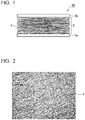
- FIG. 1 is a drawing schematically illustrating a cross-section of a sheet for a pressure sensor according to an embodiment of the present invention.
- FIG. 2 is an optical microscope photograph illustrating a planar view of a pressure-sensitive conductive layer according to an embodiment of the present invention.
- a pressure-sensitive film according to an embodiment of the present invention is described below using FIG. 1 and FIG. 2 .
- a pressure sensor sheet 10 includes a first electrode sheet 1a, a second electrode sheet 1b, and a flocculent pressure-sensitive conductive layer 3 composed of tangled conductive fibers 2, which is disposed between the first electrode sheet 1a and the second electrode sheet 1b and undergoes a change in resistance value when compressed.
- the conductive fibers 2 extend along a direction parallel to the two electrode sheets, and are stacked in the perpendicular direction.
- the pressure-sensitive conductive layer 3 has spaces between the conductive fibers 2 that constitute the layer.
- the conductive fibers may be a polymer material having a conductive material dispersed therein.
- the conductive material may be composed of one type or a plurality of types of fine particles.
- the term fine particles refers to nano-size nanomaterials or pico-size picomaterials, and means particles smaller than millimeter size.
- the flocculent pressure-sensitive conductive layer 3 composed of the tangled conductive fibers 2 is compressed, and therefore the conductive fibers 2 overlap in a dense arrangement.
- the contact surface area between the conductive fibers 2 and the first electrode sheet 1a and the second electrode sheet 1b increases.
- the shapes of the conductive fibers 2 themselves also undergo deformation.
- the pressure is weakened, the overlaps of the conductive fibers 2 become more sparse, the contact surface area between the conductive fibers 2 and the first electrode sheet 1a and the second electrode sheet 1b decreases, and the shapes of the conductive fibers 2 return to their original state.
- the changes in pressure are measured by the change in the resistance value between the first electrode sheet 1a and the second electrode sheet 1b that accompanies the above changes.
- the pressure sensor sheet 10 there are many factors that contribute to the change in resistance value, and the sheet can respond with good sensitivity even to extremely small changes in the applied pressure.
- FIG. 3 is a graph illustrating the change in the resistance value relative to the pressure applied to the pressure sensor sheet 10.
- the pressure sensor sheet 10 exhibits almost no conductivity, with a resistance value in the order of 10 10 ⁇ between the first electrode sheet 1a and the second electrode sheet 1b.
- the overlaps between the conductive fibers 2 strengthen, and the pressure sensor sheet 10 exhibits a resistance value in the order of 10 2 ⁇ between the first electrode sheet 1a and the second electrode sheet 1b. This is because the contact surface area between the conductive fibers 2 and the first electrode sheet 1a and the second electrode sheet 1b increases. In other words, the pressure sensor sheet 10 exhibits changes in the resistance value across a broad range from the order of 10 2 ⁇ to the order of 10 10 ⁇ .
- the change in the resistance value upon application of a weak pressure of 0 to 200 Pa is extremely marked.
- the pressure sensor sheet 10 can function as a sensor with high sensitivity even relative to small pressure changes.
- the conductive fibers 2 extend mainly along directions perpendicular to the direction of pressure application.
- FIG. 1 which illustrates the pressure sensor sheet 10 from a cross-sectional view
- the conductive fibers 2 are aligned mainly in parallel with the two electrode sheets.
- the pressure sensor sheet 10 because the response does not change greatly relative to expansion and contraction in directions parallel to the two electrode sheets, substantially the same response can be obtained in the case where pressure is applied in a bent state, and the case where pressure is applied in an extended state. In other words, the pressure sensor sheet 10 can perform high-precision measurements with minimal measurement noise even for pressure changes in dynamic regions. This type of high-precision measurement has been impossible to achieve with good sensitivity using conventional pressure sensor sheets formed, for example, by dispersing conductive particles in a rubber.
- FIG. 4 is a photograph showing a state in which pressure sensor sheet has been folded and a weight has then been placed on top of the sheet.
- FIG. 5 is a graph illustrating the change in resistance value when the weight shown in FIG. 4 is removed.
- a voltage of 2 V was applied between the two electrode sheets.
- a 0.4 g weight was placed on the pressure sensor sheet 3 seconds after the start of measurements, and this 0.4 g weight was removed from the pressure sensor sheet 8 seconds after the start of measurements.
- a 1.6 g weight was placed on the pressure sensor sheet 14 seconds after the start of measurements, and this 1.6 g weight was removed from the pressure sensor sheet 20 seconds after the start of measurements.
- a change in the resistance value of the pressure sensor sheet 10 occurs even when a pressure is applied with the sheet in a folded state. Further, there is a difference in the amount of current flow for the placements of the 0.4 g weight and the 1.6 g weight, indicating that the pressure sensor sheet 10 is able to detect even small differences in pressure.
- the conductive fibers 2 are tangled with spaces therebetween. As a result, light can pass through those spaces. Observation of the surface state while a pressure is being applied, measurements using light, or the application of light-based stimulus can be performed at the same time as the pressure application.
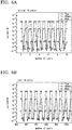
- FIG. 6A and FIG. 6B illustrate the results when a pressure of 2 kPa, 300 Pa or 80 Pa is applied repeatedly for 1,000 cycles to the pressure sensor sheet 10.
- FIG. 6A represents the results for the first 10 cycles
- FIG. 6B represents the results for the last 10 cycles.
- the results of FIGS. 6A and 6B indicate that no significant difference in the signal intensity occurs between the first 10 cycles and the last 10 cycles. In other words, the pressure sensor sheet 10 has superior repetition reproducibility.
- first electrode sheet 1a and the second electrode sheet 1b There are no particular limitations on the first electrode sheet 1a and the second electrode sheet 1b.
- a stretched sheet prepared by a method such as metal rolling may be used, or a sheet prepared by using vacuum deposition or sputtering or the like to form a layer of a metal or a transparent electrode or the like on a thin-film substrate may be used.
- transparent electrode typically used materials such as ITO, IZO and AZO may be used.
- a transparent electrode may also be formed by forming an extremely thin film of metal by vacuum deposition or sputtering or the like.
- the first electrode sheet 1a and the second electrode sheet 1b are preferably transparent electrodes.
- the conductive fibers 2 have spaces therebetween, allowing the transmission of light. Accordingly, by making the electrodes transparent, a pressure sensor sheet that transmits light can be obtained. This enables the location of the pressure measurement to be observed through the pressure sensor sheet. Further, the development of numerous other measurements becomes possible, such as simultaneously performing the pressure measurement and a measurement of light from above the pressure sensor sheet.
- the thickness of the film substrate is preferably at least 1 ⁇ m but not more than 15 ⁇ m, and is more preferably at least 1 ⁇ m but not more than 5 ⁇ m. Provided the film substrate is at least 1 ⁇ m, the film substrate can be produced stably, and sufficient film strength can be achieved. On the other hand, provided the thickness is not more than 15 ⁇ m, the pressure sensor sheet 10 exhibits substantially the same resistance value when the metal sheet is bent, and when the metal sheet is extended from a bent state using the same bend radius. Accordingly, a pressure sensor sheet 10 can be obtained that can satisfactorily accommodate operations such as bending and extending.
- the pressure sensor sheet 10 exhibits almost no change in the resistance value between a bent state and an extended state.
- the pressure sensor sheet 10 can be imparted with sensitivity only to pressure in the perpendicular direction, and the noise when the sheet is used in regions exposed to operations such as bending or extending is reduced, meaning a high degree of sensitivity can be maintained.
- Examples of materials that can be used as the film substrate include polyethylene terephthalate (PET), polyimide (PI), polyvinyl chloride (PVC), polycarbonate (PC), polyethylene naphthalate (PEN) and polyether ether ketone (PEEK).
- PET polyethylene terephthalate
- PI polyimide
- PVC polyvinyl chloride
- PC polycarbonate
- PEN polyethylene naphthalate
- PEEK polyether ether ketone
- metals or the like that can be used for the vacuum deposition or sputtering or the like include Au, Ag, Cu, Cr, Ti, Al, In, Sn, or laminated layers of these metals, and examples of transparent conductive materials that may be used include ITO and PEDOT/PSS.
- the first electrode sheet 1a or the second electrode sheet 1b preferably has air permeability.
- air permeability means the sheets do not completely block the passage of gases.
- the air permeability of the first electrode sheet 1a or the second electrode sheet 1b may be achieved by forming very fine holes in the first electrode sheet 1a or the second electrode sheet 1b, or the first electrode sheet 1a or the second electrode sheet 1b may be formed on a film having air permeability.
- the first electrode sheet 1a and the second electrode sheet 1b also both have air permeability.
- the entire pressure sensor sheet 10 can be imparted with air permeability.
- the pressure sensor sheet 10 is able to measure pressures acting upon the body surface without inhibiting the dissipation of moisture from the skin. This enables the development of a measurement system that causes no discomfort and suffers no defects even during long-term installation.
- the thicknesses of the first electrode sheet 1a and the second electrode sheet 1b are preferably substantially equal.
- the thicknesses of the first electrode sheet 1a and the second electrode sheet 1b are substantially equal, then the strain that acts upon the pressure-sensitive conductive layer 3 when the pressure sensor is subjected to bending can be reduced as far as possible. Consequently, the occurrence of errors in the measured pressure value caused by bending of the pressure sensor sheet 10 can be suppressed.
- the conductive fibers 2 that constitute the pressure-sensitive conductive layer 3 at least a portion of the fibers in those portions contacting the first electrode sheet 1a or the second electrode sheet 1b are preferably bound to the first electrode sheet 1a or the second electrode sheet 1b.
- bound means that among the conductive fibers 2, those conductive fibers 2 that contact the first electrode sheet 1a or the second electrode sheet 1b adhere naturally to the first electrode sheet 1a or the second electrode sheet 1b without the application of any external energy.
- the shapes of the conductive fibers 2 change, and the fibers bind to the first electrode sheet 1 a or the second electrode sheet 1b. If the state of the connection between the conductive fibers 2 and each of the electrode sheets is unstable, then a large amount of noise tends to occur when measurements are performed under weak pressure.
- the connection state becomes extremely stable. As a result, low-noise measurements can be performed using the pressure sensor sheet 10.
- the conductive fibers 2 that constitute the pressure-sensitive conductive layer 3 are preferably bound, at least partially, to both the first electrode sheet 1a and the second electrode sheet 1b. This leads to a structurally stable conductive path formed by the first electrode sheet 1a, the pressure-sensitive conductive layer 3 and the second electrode sheet 1b. Further, this structural stability improves the stability of the electrical state. Accordingly, measurements with even lower noise can be performed using the pressure sensor sheet 10.
- the pressure sensor sheet 10 can be formed extremely easily.
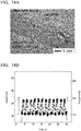
- FIG. 7 is a high-resolution cross-sectional transmission electron microscope image (TEM image) illustrating conductive fibers 2 bound to a substrate when the conductive fibers 2 are sprayed onto the substrate using an electrospinning deposition method.
- TEM image transmission electron microscope image
- the pressure sensor sheet preferably also has a second pressure-sensitive conductive layer composed of tangled second conductive fibers between the pressure-sensitive conductive layer 3 and the second electrode 1b, wherein at least a portion of the conductive fibers 2 in those portions contacting the first electrode sheet 1a are preferably bound to the first electrode sheet 1a, and at least a portion of the second conductive fibers in those portions contacting the second electrode sheet 1b are preferably bound to the second electrode sheet 1b.
- the second conductive fibers that constitute the second pressure-sensitive conductive layer may be the same as the conductive fibers described below. However, the same conductive fibers need not necessarily be used, meaning the conductive fibers and the second conductive fibers may be different.
- the pressure-sensitive conductive layer and the second pressure-sensitive conductive layer are preferably adhered together. Further, the pressure-sensitive conductive layer and the second pressure-sensitive conductive layer are preferably bound together. Adhering the pressure-sensitive conductive layer and the second pressure-sensitive conductive layer improves the structural stability of the pressure sensor sheet 10. This is accompanied by greater stability in the electrical state, making low-noise measurements possible. Furthermore, binding the pressure-sensitive conductive layer and the second pressure-sensitive conductive layer enables greater stability in the electrical state without electrically inhibiting the pressure-sensitive conductive layer and the second pressure-sensitive conductive layer, making measurements with even lower noise possible.
- adhere may describe either a self-organized bonding described as "binding” in the present description, or some other form of bonding that uses an adhesive or the like.
- the pressure-sensitive conductive layer 3 may contain not only the conductive fibers 2, but also mixed non-conductive fibers not shown in the drawings. By adjusting the mixing ratio between the conductive fibers 2 and the non-conductive fibers in the pressure-sensitive conductive layer 3, the sensitivity of the pressure sensor sheet 10 can be adjusted easily. Methods that may be used to lower the sensitivity of the pressure sensor sheet 10 and enable measurements to be performed up to high pressure include a method in which the mass ratio of the conductive material is lowered, and a method in which the conductive fibers 2 are thickened to increase the rigidity. However, reducing the mass ratio of the conductive material makes it difficult to obtain uniform resistance values. On the other hand, if the conductive are thickened, then the flexibility of the pressure sensor sheet 10 tends to be lost.
- the relationship between the pressure and the resistance value can be controlled with high precision.
- the pressure sensor sheet 10 can be prepared to best match the changes in pressure that are to be measured, meaning the sheet can be applied to all manner of applications.
- the thickness of the pressure-sensitive conductive layer 3 is preferably smaller than the combined thickness of the first electrode sheet 1a and the second electrode sheet 1b, and is preferably smaller than the thickness of either one of the first electrode sheet 1a and the second electrode sheet 1b.
- the rigidity of the sheet relative to bending must be suppressed to low levels, and the stress on the electrodes must also be suppressed.
- the sheet rigidity increases dramatically as the pressure-sensitive conductive layer 3 becomes thicker.
- the stress at the interfaces between the conductive fibers 2 and each of the electrode sheets also increases, meaning the stable connection between the conductive fibers 2 and the electrode sheets is more easily destroyed.
- the strain at the interfaces between the conductive fibers 2 and the electrode sheets is suppressed to approximately half of the strain at the electrode sheet outer surfaces, and unexpected faults during flexion of the electrode sheets and changes in the precision can be suppressed to low levels.
- the thickness of the pressure-sensitive conductive layer 3 is smaller than the thickness of either one of the first electrode sheet 1a and the second electrode sheet 1b, then strain at the connection portions between the conductive fibers 2 and each of the electrodes can be suppressed as low as possible.
- the thickness of the pressure-sensitive conductive layer 3 is preferably at least 2 times, but not more than 100 times, the diameter of the conductive fibers 2.
- the pressure-sensitive conductive layer 3 undergoes a reduction in the resistance value when the contact between the conductive fibers 2 increases due to pressure. This contact between the conductive fibers 2 is one of the principles that enables the pressure to be measured as a resistance value.
- the thickness of the pressure-sensitive conductive layer 3 is preferably a thickness corresponding with 2 layers, or 3 layers or more, of the conductive fibers 2. In other words, the thickness of the pressure-sensitive conductive layer 3 is preferably at least 2 times the diameter of the conductive fibers 2.
- the number of overlapping layers of the conductive fibers 2 increases, and localized fluctuations in the resistance value across the electrode sheets can be suppressed.
- increasing the number of stacked layers also causes an increase in the bending rigidity of the pressure sensor sheet 10 and an increase in the resistance value.
- the thickness is preferably not more than 100 ⁇ m, and more preferably 10 ⁇ m or less. If the thickness of the pressure-sensitive conductive layer 3 is 100 ⁇ m or less, then the flexibility is excellent, the sheet can satisfactorily follow objects having complex shapes or moving objects, and the sheet is able to function as a high-sensitivity, flexible sheet for a pressure sensor. If the thickness is 10 ⁇ m or less, then satisfactory transparency can be maintained.
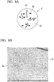
- FIG. 8A is a schematic illustration of the cross-section of the conductive fibers 2 that constitute the pressure sensor sheet 10 according to an embodiment of the present invention
- FIG. 8B is a high-resolution cross-sectional transmission electron microscope image (TEM image) of the conductive fibers 2 that constitute the pressure sensor sheet 10 according to an embodiment of the present invention.
- TEM image transmission electron microscope image
- the conductive fibers 2 preferably include at least a first conductive material 2a, a second conductive material 2b, and a polymer material 2c.
- the first conductive material 2a and the second conductive material 2b are dispersed uniformly within the conductive fibers 2. If these materials are not dispersed uniformly, then the conductive fibers 2 are unable to exhibit favorable conductivity.
- the term "conductive material” refers to a material having a conductive substance of microparticle size as a constituent element.
- the first conductive material 2a is preferably a filamentous conductive material
- the second conductive material 2b is preferably a particulate (including flake-like) conductive material.
- filamentous means that the length of the conductive material is at least 10 times the diameter of the material.
- the filamentous first conductive material 2a electrically connects particles of the particulate second conductive material 2b within the polymer material 2c.
- a weak pressure acts upon the pressure sensor sheet 10
- the conductivity through the filamentous first conductive material 2a changes, causing a reduction in the resistance value of the conductive fibers.
- the filamentous first conductive material 2a also has a secondary effect of improving the dispersion stability of the particulate second conductive material 2b in the production process for the conductive fibers 2.
- the mass ratio of the first conductive material 2a in the conductive fibers is smaller than the mass ratio of the second conductive material 2b enables an extremely large dynamic range for the change in resistance value upon pressure application. This is because by dispersing the second conductive material in a large mass ratio, a large reduction in the resistance value can be obtained when a high pressure acts upon the sheet.
- the first conductive material 2a is preferably carbon nanotubes or carbon nanohorns. Carbon nanotubes and carbon nanohorns have a certain degree of length, and therefore assist the conductivity between the dispersed particles of the second conductive material 2b, and it is thought that the shape of the carbon nanotubes or carbon nanohorns also assist uniform dispersion of the second conductive material 2b.
- Carbon nanotubes have a structure in which a single layer or multiple layers of graphene sheet having carbon atoms arranged in a hexagonal mesh have been rounded into a circular cylindrical shape.
- Single-walled nanotubes (SWNT), double-walled nanotubes (DWNT) or multi-walled nanotubes (MWNT) may be used.
- Single-walled nanotubes (SWNT) are preferable. This is because a more uniform material with better quality stability can be obtained, and because good dispersion stability can be more easily achieved.
- Carbon nanotubes can generally be produced by a laser ablation method, arc discharge method, thermal CVD method, plasma CVD method, gas phase method, or combustion method or the like, and carbon nanotubes produced using any of these types of methods may be used.
- the second conductive material 2b can use materials such as graphene, gold nanoflakes, silver nanoflakes, aluminum flakes, carbon black, gold nanoparticles, silver nanoparticles and copper nanoparticles.
- the second conductive material 2b is preferably graphene or carbon black, as graphene and carbon black exhibit extremely high conductivity and are stable.
- the first conductive material 2a is carbon nanotubes or carbon nanohorns
- the second conductive material 2b is graphene or carbon black.
- Conductive materials composed of carbon exhibit superior durability relative to oxygen and moisture, and are most suited to pressure-sensitive conductive layers 3 composed of fibers having a high specific surface area.
- the mass ratio of the first conductive material 2a is preferably smaller than the mass ratio of the second conductive material 2b.
- the mass ratio of second conductive material 2b : first conductive material 2a is preferably within a range from 3:1 to 25:1. Provided the ratio satisfies this range, the first conductive material 2a and the second conductive material 2b can be dispersed uniformly within the polymer material 2c, and conductive fibers 2 of satisfactory conductivity can be ensured.
- the mass ratio of the first conductive material 2a within the conductive fibers is preferably from 0.5 wt% to 5 wt%, and the mass ratio of the second conductive material 2b is preferably within a range from 5 wt% to 50 wt%.
- the second conductive material 2b is the main contributor to the conductivity, ensuring that the mass ratio of the second conductive material 2b is larger than the mass ratio of the first conductive material 2a can increase the degree of change in the resistance value of the pressure sensor sheet 10, thereby increasing the sensitivity of the pressure sensor sheet 10.
- the pressure sensor sheet 10 functions with higher sensitivity.
- the mass ratio of the combination of the first conductive material 2a and the second conductive material 2b within the conductive fibers 2 is preferably from 20 wt% to 50 wt%, and more preferably from 30 wt% to 40 wt%.
- the polymer material 2c may use a typically used elastomer such as a fluorine-based rubber, urethane-based rubber or silicon-based rubber, or may use a polymer material other than an elastomer, such as an acrylic, nylon or polyester.
- a typically used elastomer such as a fluorine-based rubber, urethane-based rubber or silicon-based rubber
- a polymer material other than an elastomer such as an acrylic, nylon or polyester.
- the use of an elastomer as the polymer material 2c of the conductive fibers 2 is preferable. Elastomers are flexible, and exhibit extremely little change in mechanical properties even when repeatedly subjected to large strain. When pressure is applied, large strain develops in the overlapping portions of the conductive fibers 2, but by using an elastomer as the base material, a combination of superior flexibility and superior durability can be achieved for the pressure sensor sheet.
- the polymer material 2c may be altered in accordance with the intended use of the pressure sensor sheet 10.
- the diameter of the conductive fibers 2 is preferably smaller than the thickness of the first electrode sheet 1a and the second electrode sheet 1b. If the diameter of the conductive fibers 2 is larger than each of the electrode sheets, then each electrode sheet becomes more prone to localized deformation that follows the surface of the conductive fibers 2. As a result, the state of contact between the conductive fibers 2 and the electrode sheets upon pressure application becomes irregular. Ensuring that the diameter of the conductive fibers 2 is smaller than the thickness of the first electrode sheet 1a and the second electrode sheet 1b enables suppression of any fluctuations in the change in the resistance value under pressure that may be caused by this type of irregularity in the contact state.
- the diameter of the conductive fibers 2 is preferably from 100 nm to 10 ⁇ m, and more preferably from 200 nm to 2,000 nm. If the diameter of the conductive fibers 2 changes, then the rigidity and specific surface area of the conductive fibers and the contact surface area between the conductive fibers also change, causing a change in the sensitivity of the pressure sensor sheet 10. If the diameter is from 200 nm to 2,000 nm, then the sheet can function as a pressure sensor sheet of satisfactory sensitivity. Extremely fine conductive fibers 2 have low strength, whereas extremely thick conductive fibers 2 have high rigidity and impair the flexibility of the sensor sheet. Accordingly, by ensuring that the diameter of the conductive fibers 2 is within the above range, a combination of favorable sensitivity and flexibility can be achieved.
- FIG. 9 is a schematic cross-sectional view of a pressure sensor 100 according to an embodiment of the present invention.
- the pressure sensor includes the pressure sensor sheet 10, and a transistor 20 connected to at least one of the first electrode sheet 1a and the second electrode sheet 1b of the pressure sensor sheet 10.
- a pressure sensor sheet 10 having superior flexibility is suited to measurements on surfaces having fine undulations. Accordingly, in order to enable measurement of a pressure distribution with high spatial resolution, the electrodes are divided into a multitude of segments, with a plurality of measurement points disposed on a single pressure sensor sheet 10. In order to enable the plurality of electrode segments to be arranged in a matrix, switching of each of the electrode segments with a transistor is effective. This enables a highly functional pressure sensor to be obtained.
- the pressure sensor 100 when the resistance value of the pressure sensor sheet 10 changes, the amount of current flowing through the transistor 20 changes, and externally outputting a signal corresponding with that current value enables the sensor to function as a pressure sensor 100.
- a field effect transistor such as that illustrated in FIG. 9 is used as the transistor 20
- pressure application causes a reduction in the resistance value of the pressure sensor sheet 10
- the potential difference between a source electrode 21 and a drain electrode 22 increases, and the size of the resultant current flow also increases. If the relationship between the pressure applied to the pressure sensor sheet 10 and the current is ascertained in advance, then the amount of pressure applied to the pressure sensor 100 can be detected by reading the change in the signal output corresponding with the current.
- the total thickness of the pressure sensor 100 is preferably not more than 100 ⁇ m. If the sensor is thinner than 100 ⁇ m, then it can function as an extremely flexible pressure sensor, capable of following complex shapes.
- the transistor 20 is preferably an organic transistor.
- the transistor There are no particular limitations on the construction of the transistor, and for example, a field effect transistor such as that illustrated in FIG. 9 may be used.
- the on-resistance of an organic transistor is in the order of M ⁇ , and therefore in order to cause a change in the potential difference between the source electrode 21 and the drain electrode 22, it has been thought that the change in resistance of the pressure sensor sheet 10 upon pressure application should preferably be in the order of several M ⁇ to 100 k ⁇ .
- the pressure sensor sheet 10 according to the present embodiment exhibits changes in the resistance value across a broad range from the order of 10 2 ⁇ to the order of 10 10 ⁇ , and can therefore be used very favorably.
- a method for producing a sheet for a pressure sensor includes jetting a dispersion-based liquid containing a polymer material and a conductive material onto an electrode sheet using an electrospinning deposition method, thereby forming a pressure-sensitive conductive layer composed of tangled conductive fibers.
- the electrospinning method enables the conductive fibers to be bound to the first electrode sheet without using any special adhesive or performing any special process, and is therefore ideal for forming a pressure-sensitive conductive layer composed of very fine fibers.
- the method for producing a sheet for a pressure sensor preferably includes a first step of mixing a first conductive material and an ionic liquid with a solvent to obtain a first dispersion system in which the first conductive material is dispersed within the solvent, a second step of mixing a second conductive material with a solvent to obtain a second dispersion system in which the second conductive material is dispersed within the solvent, a third step of mixing the first dispersion system and the second dispersion system to obtain a third dispersion system, a fourth step of adding an elastomer to the third dispersion system and stirring to obtain a fourth dispersion system, and a fifth step of jetting the fourth dispersion system onto a first electrode sheet using an electrospinning deposition method, thereby forming a pressure-sensitive conductive layer composed of tangled conductive fibers.
- This method for producing a sheet for a pressure sensor is described below in further detail, based on the preferred production conditions for each of the first to fifth steps.
- a first conductive material and an ionic liquid are mixed with a solvent to obtain a first dispersion system in which the first conductive material is dispersed within the solvent.
- the solvent is preferably 4-methyl-2-pentanone.
- carbon nanotubes, carbon nanohorns, or metal nanowires or the like can be used.
- EMIBF 4 or DEMEBF 4 or the like can be used as the ionic liquid.
- the ionic liquid has the role of preventing aggregation of the first conductive material.
- a shearing force is preferably applied.
- a ball mill, roller mill, vibration mill, or jet mill or the like may be used.
- the first conductive material is preferably added to a first solvent in an amount within a range from 0.2 wt% to 20 wt%. If the proportion of the first conductive material is less than 0.2 wt%, then achieving favorable conductivity becomes difficult. On the other hand, if the proportion of the first conductive material exceeds 20 wt%, then achieving uniform dispersion of the material is difficult.
- the ionic liquid is preferably added to the first solvent in an amount within a range from 1 wt% to 20 wt%. If the proportion of the ionic liquid is less than 1 wt%, then aggregation of the first conductive material cannot be satisfactorily suppressed. On the other hand, if the proportion of the ionic liquid exceeds 20 wt%, then the excess ionic liquid must be removed.
- a second conductive material is mixed with a solvent to obtain a second dispersion system in which the second conductive material is dispersed within the solvent.
- the solvent may employ the same solvent as that used in the first step.
- the second conductive material graphene, gold nanoflakes, silver nanoflakes, aluminum flakes, carbon black, gold nanoparticles, silver nanoparticles, or copper nanoparticles or the like may be used.
- a shearing force is preferably applied during the second step, and the same device as that used in the first step may be used.
- an ionic liquid may also be added and mixed, in a similar manner to the first step.
- the second conductive material is preferably added to a second solvent in an amount within a range from 10 wt% to 80 wt%, and more preferably within a range from 6 wt% to 8 wt%. If the proportion of the second conductive material is less than 10 wt%, then achieving favorable conductivity becomes difficult. On the other hand, if the proportion of the second conductive material exceeds 80 wt%, then achieving uniform dispersion of the material is difficult.
- the first dispersion system and the second dispersion system are mixed to obtain a third dispersion system.
- the solvents used in the first step and the second step are the same, it could be considered that the first conductive material and the second conductive material could simply be added to the solvent in a single batch.
- the first conductive material and the second conductive material are added in a single batch, then achieving uniform dispersion of each of the materials in the solvent tends to become more difficult. Accordingly, it is important that the first dispersion system and the second dispersion system are prepared separately, and are subsequently mixed together to obtain the third dispersion system.
- stirring is preferably performed to ensure thorough mixing of the first dispersion system and the second dispersion system. Mechanical stirring is adequate for this stirring, and heat or the like need not be applied.
- an elastomer is added to the third dispersion system and stirred to obtain a fourth dispersion system.
- a typically used elastomer such as a fluorine-based rubber, urethane-based rubber or silicon-based rubber may be used as the elastomer.
- other polymer materials may also be used, such as an acrylic, nylon or polyester.
- the mass ratio of the elastomer in the fourth dispersion system is preferably from 10 wt% to 50 wt%.
- the mass ratio of the first conductive material in the fourth dispersion system is preferably from 0.1 wt% to 5 wt%, and the mass ratio of the second conductive material is preferably from 0.5 wt% to 25 wt%.
- the mass ratio of the elastomer is less than 10 wt%, then solvent evaporation during the electrospinning process may take too long, and favorable fiber formation may become difficult. On the other hand, if the mass ratio of the elastomer exceeds 50 wt%, then the viscosity increases, making it difficult to achieve uniform dispersion of the first conductive material and the second conductive material.
- the sensitivity and the range of resistance values for the pressure sensor sheet can be modified.
- the stirring in the fourth step is preferably performed for at least 4 hours. Adding the elastomer increases the viscosity of the dispersion system, and therefore performing thorough stirring is necessary.
- the fourth dispersion system is subjected to electrospinning deposition to form a pressure-sensitive conductive layer having tangled conductive fibers.
- the electrospinning deposition method is described using FIG. 10 .
- the fourth dispersion system 4 inside a syringe 5 is forced from the syringe while a high voltage is applied between the needle 5a of the syringe 5 and the first electrode sheet 1a. At this time, because of the potential difference between the needle 5a and the first electrode sheet 1a, the fourth dispersion system 4 is drawn rapidly from the syringe 5 and sprayed toward the first electrode sheet 1a. This sprayed fourth dispersion system 4 is deposited on the top of the first electrode sheet 1a in a flocculent form as the conductive fibers 2.
- the solvent of the fourth dispersion system 4 evaporates almost completely between the needle 5 a and the first electrode sheet 1a, and therefore the majority of the solvent within the conductive fibers 2 has evaporated at the point the fibers are deposited on the first electrode sheet 1a in a flocculent form.
- the solvent within the conductive fibers 2 deposited on the first electrode sheet 1a has not evaporated completely.
- this residual solvent within the conductive fibers 2 evaporates on the first electrode sheet 1a.
- the shape of the conductive fibers 2 changes to a kamaboko-type shape illustrated in FIG. 7 , thereby binding together the first electrode sheet 1a and the conductive fibers 2.
- the first electrode sheet 1a and the conductive fibers 2 can be bound without requiring the use of extra adhesive or the like, and a pressure sensor of higher sensitivity can be produced.
- the distance between the needle 5a and the first electrode sheet 1a is preferably within a range from 10 cm to 50 cm.
- the method may further include a step of jetting a dispersion-based liquid containing a polymer material and a conductive material onto the second electrode sheet using an electrospinning deposition method, thereby forming second a pressure-sensitive conductive layer composed of tangled conductive fibers, and a step of binding together the pressure-sensitive conductive layer formed on the first electrode sheet and the second pressure-sensitive conductive layer formed on the second electrode sheet.
- the pressure-sensitive conductive layer and the second pressure-sensitive conductive layer are each composed of tangled conductive fibers, simply bringing the pressure-sensitive conductive layer and the second pressure-sensitive conductive layer into contact causes the respective conductive fibers to become tangled and bind together, producing satisfactory structural stability.
- the fourth dispersion system 4 is pulled rapidly from the fine aperture of the needle 5a due to the potential difference. At this time, the fourth dispersion system 4 is subjected to shearing forces, and therefore any aggregates of the first conductive material or the second conductive material that had not been completely dispersed within the fourth dispersion system are eliminated. For this reason, the aperture of the needle 5a is preferably within a range from 0.2 mm to 2 mm.
- the pressure-sensitive conductive layer is preferably formed by placing the respective raw materials in two syringes, and performing simultaneous electrodeposition spinning. If the conductive fibers 2 and the non-conductive fibers are formed by sequential deposition by electrodeposition spinning, then regions with conductivity and regions without conductivity may develop within the pressure-sensitive conductive layer, resulting in a lack of uniformity in the conductivity.
- the fifth step is performed within 24 hours of completing the fourth step.
- the fifth step is more preferably performed within 12 hours of the fourth step. If the fourth dispersion system is left to stand for longer than 24 hours, then the dispersed first conductive material and second conductive material may re-aggregate. If the fourth dispersion system is left to stand for longer than 12 hours, then even using the shearing forces that occur as the dispersion system passes through the fine aperture of the needle 5a, re-dispersion of the first conductive material and the second conductive material may become impossible.
- a first step 0.6 wt% of carbon nanotubes and 2 wt% of an ionic liquid were mixed with a solvent of 4-methyl-2-pentanone.
- a high-pressure jet mill homogenizer 60 MPa, Nano-jet pal, JN10, manufactured by Jokoh Co., Ltd.
- a first dispersion system was obtained in which the carbon nanotubes were dispersed uniformly within the solvent composed of 4-methyl-2-pentanone.
- the first dispersion system and the second dispersion system are stirred for 2 hours with a stirrer, thus obtaining a third dispersion system.
- a fluorine-based rubber G-912 product name, manufactured by Daikin Industries, Ltd.
- a fluorine-based rubber G-912 product name, manufactured by Daikin Industries, Ltd.
- the proportions of the elastomer, the carbon nanotubes and the graphene within the fourth dispersion system were 0.3 wt%, 3 wt% and 25 wt% respectively.
- the obtained fourth dispersion system was placed in a syringe having a needle aperture of 20 nm, and an electrode sheet was installed in a position 25 cm from the tip of the needle.
- a voltage of 25 kV was then applied between the needle and the electrode sheet, and the fourth dispersion system was discharged from the syringe at a rate of 10 ⁇ l/min, thus forming a pressure-sensitive conductive layer having a size of 20 cm ⁇ 20 cm square and composed of tangled conductive fibers on the electrode sheet by electrospinning deposition.
- the thickness of the thus obtained pressure-sensitive conductive layer was 4 ⁇ m.
- the electrode sheet was prepared by layering 50 nm of Au on a PET film of 1.4 ⁇ m.
- the diameter of the conductive fibers was 300 nm to 400 nm, the mass ratio of the first conductive material within the conductive fibers was 1 wt%, and the mass ratio of the second conductive material was 12 wt%.
- FIG. 11 is a photograph of the pressure sensor sheet of Example 1. The total thickness of this pressure sensor sheet was 7 ⁇ m.
- Example 2 with the exception of the fifth step, a pressure sensor was prepared using the same production method as that of Example 1.
- another syringe was also prepared containing a solution that differed from the fourth dispersion system only in not containing any conductive material.
- the fourth dispersion system and the solution containing no conductive materials were then discharged simultaneously from the two syringes, forming a pressure-sensitive conductive layer having a size of 20 cm ⁇ 20 cm square on an electrode sheet by electrospinning deposition.
- the diameters of the syringe needles, the distance between the needles and the electrode sheet, and the voltage applied between the needles and the electrode sheet were the same as Example 1.
- the thickness of the thus obtained pressure-sensitive conductive layer was 4 ⁇ m, and the non-conductive fibers were mixed into the pressure-sensitive conductive layer with a ratio of conductive fibers : non-conductive fibers of 1:1.
- the electrode sheet was prepared by layering 50 nm of Au on a PET film of 1.4 ⁇ m.
- the diameter of the conductive fibers was 300 nm to 400 nm, the mass ratio of the first conductive material within the conductive fibers was 1 wt%, and the mass ratio of the second conductive material was 12 wt%.
- the total thickness of this pressure sensor sheet was 7 ⁇ m.
- FIG. 12 is a graph illustrating the change in the resistance value relative to the pressure applied to the pressure sensor sheets of Example 1 and Example 2.
- the pressure sensor sheet of Example 1 exhibited a change in the resistance value within a range from the order of 10 2 ⁇ to the order of 10 10 ⁇
- the pressure sensor sheet of Example 2 exhibited a change in the resistance value within a range from the order of 10 4 ⁇ to the order of 10 10 ⁇ , with both pressure sensor sheets exhibiting extremely large changes in the resistance value relative to applied pressure.
- the pressure sensor sheet of Example 2 Compared with the pressure sensor sheet of Example 1, the pressure sensor sheet of Example 2 exhibited a smaller change in the resistance value and different sensitivity. This is because the pressure sensor sheet of Example 2 included a mixture of conductive fibers and non-conductive fibers, resulting in a duller sensitivity compared with the pressure sensor sheet of Example 1 composed of only conductive fibers. In other words, by changing the mixing ratio between the conductive fibers and the non-conductive fibers in the pressure sensor sheet, the sensitivity of the pressure sensor sheet can easily be adjusted.
- Example 3 with the exception of forming an organic field effect transistor on a PI film of thickness 12.5 ⁇ m, a pressure sensor was prepared using the same production method as Example 1. The thickness of the obtained pressure sensor was 29 ⁇ m.
- Example 4 with the exception of forming an organic field effect transistor on a PI film of thickness 75 ⁇ m, a pressure sensor was prepared using the same production method as Example 1. The thickness of the obtained pressure sensor was 154 ⁇ m.
- FIG. 13 is a graph illustrating the change in the resistance value relative to the bend radius, when the pressure sensor sheets of Example 1, Example 3 and Example 4 were subjected to bending.
- Examples 1 and 2 exhibited the same resistance value at the same bend radius even when exposed to bending and extending, confirming that the sheets were able to satisfactorily accommodate bending and extending and the like, and were able to function as flexible pressure sensor sheets.
- the pressure sensor sheet of Example 1 exhibited no change in the resistance value from the extended state, even in a state where the bend radius was close to 0mm (a state in which the pressure sensor sheet was almost folded in two). In other words, it was evident that the pressure sensor sheet undergoes almost no reaction to pressure applied parallel to the sheet. Hence, only pressure applied in a direction perpendicular to the pressure sensor sheet can be measured with good precision, meaning the sheet is particularly suitable as a pressure sensor sheet for objects having complex shapes or objects that are exposed to movements such as bending and extending.
- FIG. 14A is a photograph showing the pressure sensor sheet of Example 1 installed on an artificial blood vessel formed from a silicone tube
- FIG. 14B illustrates the measurement results when the artificial blood vessel was pulsed.
- a blood vessel pulse was simulated by feeding a liquid through the artificial blood vessel at alternating pressures of 80 mmHg and 120 mmHg. As illustrated in FIG. 14B , it is clear that the resulting electric current changed in accordance with the pulses. In other words, the sheet was able to suitably follow a moving object, and was capable of measuring, with superior sensitivity, a pressure applied to the moving object.
- Example 6 differs in that the first step of Example 1 was not performed.
- the pressure sensor sheet of Example 6 differed from the pressure sensor sheet of Example 1 in that only graphene was used as the conductive material within the conductive fibers.
- FIG. 15 is a graph illustrating the change in the resistance value relative to the pressure applied to the pressure sensor sheets according to Example 1 and Example 6. Although the pressure sensor sheet of Example 6 exhibited inferior sensitivity of the change in resistance value relative to applied pressure compared with the pressure sensor sheet of Example 1, it was still capable of functioning satisfactorily as a pressure sensor.
Applications Claiming Priority (2)
| Application Number | Priority Date | Filing Date | Title |
|---|---|---|---|
| JP2014021488 | 2014-02-06 | ||
| PCT/JP2015/053287 WO2015119211A1 (fr) | 2014-02-06 | 2015-02-05 | Feuille pour capteur de pression, capteur de pression, et procédé de production de feuille pour capteur de pression |
Publications (3)
| Publication Number | Publication Date |
|---|---|
| EP3104150A1 true EP3104150A1 (fr) | 2016-12-14 |
| EP3104150A4 EP3104150A4 (fr) | 2017-10-11 |
| EP3104150B1 EP3104150B1 (fr) | 2020-03-11 |
Family
ID=53778012
Family Applications (1)
| Application Number | Title | Priority Date | Filing Date |
|---|---|---|---|
| EP15746322.5A Active EP3104150B1 (fr) | 2014-02-06 | 2015-02-05 | Feuille pour capteur de pression, capteur de pression, et procédé de production de feuille pour capteur de pression |
Country Status (6)
| Country | Link |
|---|---|
| US (1) | US10401240B2 (fr) |
| EP (1) | EP3104150B1 (fr) |
| JP (1) | JP6424408B2 (fr) |
| KR (1) | KR102254942B1 (fr) |
| CN (1) | CN105960581B (fr) |
| WO (1) | WO2015119211A1 (fr) |
Families Citing this family (29)
| Publication number | Priority date | Publication date | Assignee | Title |
|---|---|---|---|---|
| KR20180061344A (ko) | 2015-10-07 | 2018-06-07 | 더 리전트 오브 더 유니버시티 오브 캘리포니아 | 그래핀-기반의 다중-모드형 센서 |
| KR102427788B1 (ko) * | 2016-02-02 | 2022-08-02 | 주식회사 아모센스 | 터치압력 감지 센서 |
| JP7176411B2 (ja) | 2016-08-25 | 2022-11-22 | 日本電気株式会社 | フレキシブル電極及びセンサー素子 |
| EP3509408B1 (fr) * | 2016-09-05 | 2021-11-10 | Nec Corporation | Matériau absorbant les ondes électromagnétiques |
| JP6596170B2 (ja) * | 2016-11-11 | 2019-10-23 | 株式会社フジクラ | 荷重検知センサ及び荷重検知センサユニット |
| CN108344532A (zh) * | 2017-01-23 | 2018-07-31 | 华邦电子股份有限公司 | 压力传感器及其制造方法 |
| EP3781903A4 (fr) * | 2018-04-19 | 2022-04-20 | Texavie Technologies Inc. | Procédés et systèmes d'estimation d'une topographie d'au moins deux parties d'un corps |
| CN110411626B (zh) * | 2018-04-28 | 2021-05-11 | 五邑大学 | 一种基于交叉结构的测力计 |
| CN110411620B (zh) * | 2018-04-28 | 2021-05-11 | 五邑大学 | 一种阈值可调的测力计 |
| JP7059795B2 (ja) * | 2018-05-18 | 2022-04-26 | オムロン株式会社 | 圧力センサ、圧力センサモジュール、及びロボットハンド |
| JP6952645B2 (ja) * | 2018-05-22 | 2021-10-20 | ニッタ株式会社 | 感圧センサー |
| CN109029801B (zh) * | 2018-05-25 | 2020-04-28 | 苏州大学 | 一种金属纳米线复合膜压力传感器及其制备方法 |
| CN109100062B (zh) * | 2018-07-10 | 2020-11-24 | 吉林大学 | 一种通过控制三维导电纱网结构制造压阻传感器的方法 |
| KR102154011B1 (ko) * | 2018-08-27 | 2020-09-09 | 스피나 시스템즈 주식회사 | 압력 센서를 이용한 치아 교합 측정기 및 이의 제조 방법 |
| CN109211443A (zh) * | 2018-09-18 | 2019-01-15 | 常州大学 | 一种弯曲不敏感压力传感器 |
| JP7183700B2 (ja) * | 2018-10-29 | 2022-12-06 | セイコーエプソン株式会社 | 感圧センサーおよびハンド |
| CN109781315B (zh) * | 2019-02-02 | 2020-08-25 | 五邑大学 | 一种触觉传感器 |
| CN217878102U (zh) * | 2019-06-05 | 2022-11-22 | 液态电线公司 | 具有选择性约束的可变形传感器 |
| CN110285898B (zh) * | 2019-08-06 | 2020-04-24 | 清华大学 | 基于碳黑无尘纸的柔性压力传感装置及其制造方法 |
| CN110608825B (zh) * | 2019-09-12 | 2021-08-20 | 复旦大学 | 基于聚酰亚胺基底微结构的柔性压力传感器及其制备方法 |
| WO2021106227A1 (fr) * | 2019-11-29 | 2021-06-03 | 村田機械株式会社 | Capteur de pression de contact, article en tricot équipé de celui-ci, et procédé de fabrication d'un capteur de pression de contact |
| WO2021222164A1 (fr) * | 2020-04-27 | 2021-11-04 | Virginia Tech Intellectual Properties Inc. | Fibre polymère de détection de déformation étirable, dispositifs fabriqués avec celle-ci, et procédé de fabrication de fibre polymère de détection de déformation étirable |
| CN112161738B (zh) * | 2020-09-17 | 2022-04-08 | 五邑大学 | 气压传感器及制作方法 |
| KR102389249B1 (ko) * | 2020-09-24 | 2022-04-22 | 한국과학기술연구원 | 정렬된 카본 나노튜브 시트를 포함하는 압력 센서 및 이를 제조하는 방법 |
| CN113913952B (zh) * | 2021-09-29 | 2023-04-14 | 北京航空航天大学 | 一种三明治结构的聚酰亚胺基电磁屏蔽薄膜及其制备方法 |
| KR102604229B1 (ko) * | 2021-12-23 | 2023-11-20 | 광운대학교 산학협력단 | 전기방사 기반 수소결합 하이브리드 나노 섬유 막 과 압력센서 및 그 제조방법 |
| CN114993527B (zh) * | 2022-05-31 | 2023-02-28 | 电子科技大学 | 基于碳化静电纺丝纤维的柔性电阻式压力传感器及制备 |
| CN116913582B (zh) * | 2023-08-03 | 2024-02-23 | 广州恒星传导科技股份有限公司 | 一种应用在刹车片磨损监控上的线缆 |
| CN116835523B (zh) * | 2023-08-31 | 2023-11-28 | 常州天策电子科技有限公司 | 基于纳米线阵列薄膜压力传感器的制备方法及压力传感器 |
Family Cites Families (39)
| Publication number | Priority date | Publication date | Assignee | Title |
|---|---|---|---|---|
| JPS57132033A (en) * | 1981-02-09 | 1982-08-16 | Sharp Corp | Pressure sensor |
| US7123216B1 (en) * | 1994-05-05 | 2006-10-17 | Idc, Llc | Photonic MEMS and structures |
| US6809280B2 (en) | 2002-05-02 | 2004-10-26 | 3M Innovative Properties Company | Pressure activated switch and touch panel |
| JP2004125571A (ja) * | 2002-10-01 | 2004-04-22 | National Institute Of Advanced Industrial & Technology | 透明圧電センサおよびそれを備えた入力装置 |
| WO2004031711A1 (fr) | 2002-10-01 | 2004-04-15 | National Institute Of Advanced Industrial Science And Technology | Capteur piezoelectrique et dispositif d'entree le comprenant |
| CN100389472C (zh) * | 2003-01-23 | 2008-05-21 | 上海奥威科技开发有限公司 | 一种混合型超级电容器制造方法 |
| US7367836B2 (en) * | 2004-07-13 | 2008-05-06 | Emerson Network Power-Embedded Computing, Inc. | RTM alignment and keying mechanism |
| JP2006153471A (ja) * | 2004-11-25 | 2006-06-15 | Hitachi Cable Ltd | 感圧センサ |
| JP5135757B2 (ja) * | 2006-01-13 | 2013-02-06 | 日産自動車株式会社 | 導電性高分子からなる布帛を用いたセンサ、アクチュエータ |
| JP5467322B2 (ja) | 2006-12-11 | 2014-04-09 | 国立大学法人名古屋大学 | 感圧シート |
| US20100162832A1 (en) * | 2007-02-23 | 2010-07-01 | Koninklijke Philips Electronics N.V. | Shear force and pressure measurement in wearable textiles |
| CN101303264B (zh) * | 2007-05-09 | 2010-05-26 | 清华大学 | 电离规 |
| DE102007040762A1 (de) * | 2007-08-29 | 2009-03-05 | Bayer Materialscience Ag | Vorrichtung und Verfahren zur Herstellung von elektrisch leitenden Nanostrukturen mittels Elektrospinnen |
| US8108157B2 (en) | 2008-02-18 | 2012-01-31 | The University Of Akron | Electrospun fibrous nanocomposites as permeable, flexible strain sensors |
| JP2010014694A (ja) * | 2008-06-04 | 2010-01-21 | Nissan Motor Co Ltd | 負荷検知繊維 |
| JP2010101827A (ja) | 2008-10-27 | 2010-05-06 | Kuraray Co Ltd | 圧力検知装置 |
| CN102032964B (zh) * | 2009-09-29 | 2012-05-02 | 张美超 | 感压膜及其使用方法 |
| US9099224B2 (en) * | 2009-10-01 | 2015-08-04 | Board Of Supervisors Of Louisiana State University And Agricultural And Mechanical College | Apparatus and method for nanocomposite sensors |
| JP5668966B2 (ja) * | 2009-10-15 | 2015-02-12 | 株式会社槌屋 | 導電性織物及び導電性織物を使用したタッチセンサ装置 |
| CN102074648B (zh) * | 2009-11-24 | 2015-04-15 | 清华大学 | 压电元件及其制备方法 |
| CN102656007A (zh) * | 2009-11-30 | 2012-09-05 | 南洋理工学院 | 有孔膜传感器 |
| FR2953824B1 (fr) * | 2009-12-11 | 2015-04-24 | Univ Toulouse 3 Paul Sabatier | Materiau solide composite piezoelectrique et/ou pyroelectrique, procede d'obtention et utilisation d'un tel materiau |
| CN102136836B (zh) | 2010-01-22 | 2013-02-13 | 清华大学 | 压控开关、其应用方法及使用该压控开关的报警系统 |
| KR101225143B1 (ko) * | 2010-02-24 | 2013-01-25 | (주)씨아이제이 | 연성 전극소재 및 그 제조방법 |
| KR101222028B1 (ko) * | 2010-07-20 | 2013-01-14 | 한국표준과학연구원 | 신축성 촉각센서의 제조방법 |
| JP5561599B2 (ja) * | 2010-07-20 | 2014-07-30 | 国立大学法人大阪大学 | 導電性ワイヤの製造装置、導電性ワイヤの製造方法及び配線基板の製造方法 |
| JP5636290B2 (ja) | 2011-01-12 | 2014-12-03 | キヤノン化成株式会社 | 感圧センサ |
| CN103429530B (zh) * | 2011-02-28 | 2015-11-25 | 国立研究开发法人科学技术振兴机构 | 石墨烯的制造方法、基板上制造的石墨烯以及基板上的石墨烯 |
| TWI442035B (zh) | 2011-07-22 | 2014-06-21 | Univ Nat Taiwan | 壓力感測器及感測陣列 |
| JP2013068562A (ja) | 2011-09-26 | 2013-04-18 | Fujikura Ltd | 圧力センサ |
| CN103063332A (zh) * | 2011-10-19 | 2013-04-24 | 郭松 | 柔软材料压力传感器用柔软感应材料的设计方法 |
| JP5924725B2 (ja) * | 2011-11-14 | 2016-05-25 | ヤマハ株式会社 | 歪みセンサ及び歪みセンサの製造方法 |
| JP2013136141A (ja) | 2011-11-30 | 2013-07-11 | Canon Inc | 把持装置、ロボット装置及び把持装置の制御方法 |
| WO2013131549A1 (fr) * | 2012-03-05 | 2013-09-12 | Prysmian S.P.A. | Procédé de détection d'une torsion dans un câble, câble électrique comportant un capteur de torsion et procédé de fabrication dudit câble |
| JP2013195331A (ja) * | 2012-03-22 | 2013-09-30 | Jsr Corp | 異方導電性シートおよびその用途 |
| CN102717536B (zh) * | 2012-04-12 | 2014-10-15 | 东华大学 | 一种碳纳米管导电复合膜的制备方法 |
| KR101412623B1 (ko) * | 2012-05-10 | 2014-07-01 | 한국표준과학연구원 | 압저항 센싱감도가 향상된 탄소나노튜브 복합체 및 그 제조방법, 이 탄소나노튜브 복합체를 갖는 압력감응센서 |
| CN102692288B (zh) | 2012-06-15 | 2014-03-19 | 青岛大学 | 一种柔性力敏传感器的制备方法 |
| CN103208618B (zh) * | 2013-04-24 | 2015-10-28 | 中国科学院苏州纳米技术与纳米仿生研究所 | 锂离子电池碳硫复合正极材料及其制备方法 |
-
2015
- 2015-02-05 CN CN201580007199.3A patent/CN105960581B/zh not_active Expired - Fee Related
- 2015-02-05 EP EP15746322.5A patent/EP3104150B1/fr active Active
- 2015-02-05 US US15/116,003 patent/US10401240B2/en not_active Expired - Fee Related
- 2015-02-05 WO PCT/JP2015/053287 patent/WO2015119211A1/fr active Application Filing
- 2015-02-05 KR KR1020167019596A patent/KR102254942B1/ko active IP Right Grant
- 2015-02-05 JP JP2015561033A patent/JP6424408B2/ja not_active Expired - Fee Related
Also Published As
| Publication number | Publication date |
|---|---|
| KR20160117439A (ko) | 2016-10-10 |
| KR102254942B1 (ko) | 2021-05-24 |
| EP3104150B1 (fr) | 2020-03-11 |
| US10401240B2 (en) | 2019-09-03 |
| JPWO2015119211A1 (ja) | 2017-03-23 |
| US20170167928A1 (en) | 2017-06-15 |
| EP3104150A4 (fr) | 2017-10-11 |
| WO2015119211A1 (fr) | 2015-08-13 |
| CN105960581B (zh) | 2022-04-08 |
| JP6424408B2 (ja) | 2018-11-21 |
| CN105960581A (zh) | 2016-09-21 |
Similar Documents
| Publication | Publication Date | Title |
|---|---|---|
| EP3104150B1 (fr) | Feuille pour capteur de pression, capteur de pression, et procédé de production de feuille pour capteur de pression | |
| Chatterjee et al. | Electrically conductive coatings for fiber-based e-textiles | |
| Yan et al. | Stretchable graphene thermistor with tunable thermal index | |
| Wu et al. | Highly flexible and sensitive wearable e-skin based on graphite nanoplatelet and polyurethane nanocomposite films in mass industry production available | |
| Gong et al. | A wearable and highly sensitive pressure sensor with ultrathin gold nanowires | |
| Yoon et al. | Cost-effective stretchable Ag nanoparticles electrodes fabrication by screen printing for wearable strain sensors | |
| Wei et al. | Highly stable and sensitive paper-based bending sensor using silver nanowires/layered double hydroxides hybrids | |
| Zhao et al. | Highly sensitive flexible strain sensor based on threadlike spandex substrate coating with conductive nanocomposites for wearable electronic skin | |
| Sorel et al. | The dependence of the optoelectrical properties of silver nanowire networks on nanowire length and diameter | |
| TWI682405B (zh) | 導電性銀糊劑 | |
| JP6212814B2 (ja) | 多点プローブ及びそれを構成する電子接点シート、多点プローブアレイ並びに多点プローブの製造方法 | |
| Boland et al. | Surface coatings of silver nanowires lead to effective, high conductivity, high-strain, ultrathin sensors | |
| EP3056547B1 (fr) | Matériau conducteur et transducteur l'utilisant | |
| Moheimani et al. | Thermoplastic polyurethane flexible capacitive proximity sensor reinforced by CNTs for applications in the creative industries | |
| An et al. | A wearable and highly sensitive textile-based pressure sensor with Ti3C2Tx nanosheets | |
| Zhang et al. | High-performance strain sensor based on a 3D conductive structure for wearable electronics | |
| You et al. | Graphene-based fiber sensors with high stretchability and sensitivity by direct ink extrusion | |
| Zhuang et al. | Wearable strain sensor based on highly conductive carbon nanotube/polyurethane composite fibers | |
| Lee et al. | Reinforcing Ag nanoparticle thin films with very long Ag nanowires | |
| Hwang et al. | Lubricant-added conductive composite for direct writing of a stretchable electrode | |
| Selvan T et al. | Printable carbon nanotube-liquid elastomer-based multifunctional adhesive sensors for monitoring physiological parameters | |
| Song et al. | Electrostatic jet engineering of flexible composite pressure sensors for physical applications | |
| Walter et al. | CNT/Graphite/SBS conductive fibers for strain sensing in wearable telerehabilitation devices | |
| Li et al. | A crack compensation strategy for highly stretchable conductors based on liquid metal inclusions | |
| Bai et al. | 3D printing of flexible strain sensor based on MWCNTs/flexible resin composite |
Legal Events
| Date | Code | Title | Description |
|---|---|---|---|
| PUAI | Public reference made under article 153(3) epc to a published international application that has entered the european phase |
Free format text: ORIGINAL CODE: 0009012 |
|
| STAA | Information on the status of an ep patent application or granted ep patent |
Free format text: STATUS: REQUEST FOR EXAMINATION WAS MADE |
|
| 17P | Request for examination filed |
Effective date: 20160728 |
|
| AK | Designated contracting states |
Kind code of ref document: A1 Designated state(s): AL AT BE BG CH CY CZ DE DK EE ES FI FR GB GR HR HU IE IS IT LI LT LU LV MC MK MT NL NO PL PT RO RS SE SI SK SM TR |
|
| AX | Request for extension of the european patent |
Extension state: BA ME |
|
| DAX | Request for extension of the european patent (deleted) | ||
| A4 | Supplementary search report drawn up and despatched |
Effective date: 20170911 |
|
| RIC1 | Information provided on ipc code assigned before grant |
Ipc: G01L 1/22 20060101ALI20170905BHEP Ipc: G01L 1/20 20060101AFI20170905BHEP Ipc: D01D 5/00 20060101ALI20170905BHEP |
|
| STAA | Information on the status of an ep patent application or granted ep patent |
Free format text: STATUS: EXAMINATION IS IN PROGRESS |
|
| 17Q | First examination report despatched |
Effective date: 20181206 |
|
| GRAP | Despatch of communication of intention to grant a patent |
Free format text: ORIGINAL CODE: EPIDOSNIGR1 |
|
| STAA | Information on the status of an ep patent application or granted ep patent |
Free format text: STATUS: GRANT OF PATENT IS INTENDED |
|
| INTG | Intention to grant announced |
Effective date: 20191216 |
|
| GRAS | Grant fee paid |
Free format text: ORIGINAL CODE: EPIDOSNIGR3 |
|
| GRAA | (expected) grant |
Free format text: ORIGINAL CODE: 0009210 |
|
| STAA | Information on the status of an ep patent application or granted ep patent |
Free format text: STATUS: THE PATENT HAS BEEN GRANTED |
|
| AK | Designated contracting states |
Kind code of ref document: B1 Designated state(s): AL AT BE BG CH CY CZ DE DK EE ES FI FR GB GR HR HU IE IS IT LI LT LU LV MC MK MT NL NO PL PT RO RS SE SI SK SM TR |
|
| REG | Reference to a national code |
Ref country code: GB Ref legal event code: FG4D |
|
| REG | Reference to a national code |
Ref country code: CH Ref legal event code: EP |
|
| REG | Reference to a national code |
Ref country code: AT Ref legal event code: REF Ref document number: 1243731 Country of ref document: AT Kind code of ref document: T Effective date: 20200315 |
|
| REG | Reference to a national code |
Ref country code: IE Ref legal event code: FG4D |
|
| REG | Reference to a national code |
Ref country code: DE Ref legal event code: R096 Ref document number: 602015048599 Country of ref document: DE |
|
| PG25 | Lapsed in a contracting state [announced via postgrant information from national office to epo] |
Ref country code: FI Free format text: LAPSE BECAUSE OF FAILURE TO SUBMIT A TRANSLATION OF THE DESCRIPTION OR TO PAY THE FEE WITHIN THE PRESCRIBED TIME-LIMIT Effective date: 20200311 Ref country code: RS Free format text: LAPSE BECAUSE OF FAILURE TO SUBMIT A TRANSLATION OF THE DESCRIPTION OR TO PAY THE FEE WITHIN THE PRESCRIBED TIME-LIMIT Effective date: 20200311 Ref country code: NO Free format text: LAPSE BECAUSE OF FAILURE TO SUBMIT A TRANSLATION OF THE DESCRIPTION OR TO PAY THE FEE WITHIN THE PRESCRIBED TIME-LIMIT Effective date: 20200611 |
|
| REG | Reference to a national code |
Ref country code: NL Ref legal event code: MP Effective date: 20200311 |
|
| PG25 | Lapsed in a contracting state [announced via postgrant information from national office to epo] |
Ref country code: BG Free format text: LAPSE BECAUSE OF FAILURE TO SUBMIT A TRANSLATION OF THE DESCRIPTION OR TO PAY THE FEE WITHIN THE PRESCRIBED TIME-LIMIT Effective date: 20200611 Ref country code: LV Free format text: LAPSE BECAUSE OF FAILURE TO SUBMIT A TRANSLATION OF THE DESCRIPTION OR TO PAY THE FEE WITHIN THE PRESCRIBED TIME-LIMIT Effective date: 20200311 Ref country code: SE Free format text: LAPSE BECAUSE OF FAILURE TO SUBMIT A TRANSLATION OF THE DESCRIPTION OR TO PAY THE FEE WITHIN THE PRESCRIBED TIME-LIMIT Effective date: 20200311 Ref country code: HR Free format text: LAPSE BECAUSE OF FAILURE TO SUBMIT A TRANSLATION OF THE DESCRIPTION OR TO PAY THE FEE WITHIN THE PRESCRIBED TIME-LIMIT Effective date: 20200311 Ref country code: GR Free format text: LAPSE BECAUSE OF FAILURE TO SUBMIT A TRANSLATION OF THE DESCRIPTION OR TO PAY THE FEE WITHIN THE PRESCRIBED TIME-LIMIT Effective date: 20200612 |
|
| REG | Reference to a national code |
Ref country code: LT Ref legal event code: MG4D |
|
| PG25 | Lapsed in a contracting state [announced via postgrant information from national office to epo] |
Ref country code: NL Free format text: LAPSE BECAUSE OF FAILURE TO SUBMIT A TRANSLATION OF THE DESCRIPTION OR TO PAY THE FEE WITHIN THE PRESCRIBED TIME-LIMIT Effective date: 20200311 |
|
| PG25 | Lapsed in a contracting state [announced via postgrant information from national office to epo] |
Ref country code: SK Free format text: LAPSE BECAUSE OF FAILURE TO SUBMIT A TRANSLATION OF THE DESCRIPTION OR TO PAY THE FEE WITHIN THE PRESCRIBED TIME-LIMIT Effective date: 20200311 Ref country code: LT Free format text: LAPSE BECAUSE OF FAILURE TO SUBMIT A TRANSLATION OF THE DESCRIPTION OR TO PAY THE FEE WITHIN THE PRESCRIBED TIME-LIMIT Effective date: 20200311 Ref country code: EE Free format text: LAPSE BECAUSE OF FAILURE TO SUBMIT A TRANSLATION OF THE DESCRIPTION OR TO PAY THE FEE WITHIN THE PRESCRIBED TIME-LIMIT Effective date: 20200311 Ref country code: SM Free format text: LAPSE BECAUSE OF FAILURE TO SUBMIT A TRANSLATION OF THE DESCRIPTION OR TO PAY THE FEE WITHIN THE PRESCRIBED TIME-LIMIT Effective date: 20200311 Ref country code: RO Free format text: LAPSE BECAUSE OF FAILURE TO SUBMIT A TRANSLATION OF THE DESCRIPTION OR TO PAY THE FEE WITHIN THE PRESCRIBED TIME-LIMIT Effective date: 20200311 Ref country code: IS Free format text: LAPSE BECAUSE OF FAILURE TO SUBMIT A TRANSLATION OF THE DESCRIPTION OR TO PAY THE FEE WITHIN THE PRESCRIBED TIME-LIMIT Effective date: 20200711 Ref country code: PT Free format text: LAPSE BECAUSE OF FAILURE TO SUBMIT A TRANSLATION OF THE DESCRIPTION OR TO PAY THE FEE WITHIN THE PRESCRIBED TIME-LIMIT Effective date: 20200805 Ref country code: CZ Free format text: LAPSE BECAUSE OF FAILURE TO SUBMIT A TRANSLATION OF THE DESCRIPTION OR TO PAY THE FEE WITHIN THE PRESCRIBED TIME-LIMIT Effective date: 20200311 |
|
| REG | Reference to a national code |
Ref country code: AT Ref legal event code: MK05 Ref document number: 1243731 Country of ref document: AT Kind code of ref document: T Effective date: 20200311 |
|
| REG | Reference to a national code |
Ref country code: DE Ref legal event code: R097 Ref document number: 602015048599 Country of ref document: DE |
|
| PLBE | No opposition filed within time limit |
Free format text: ORIGINAL CODE: 0009261 |
|
| STAA | Information on the status of an ep patent application or granted ep patent |
Free format text: STATUS: NO OPPOSITION FILED WITHIN TIME LIMIT |
|
| PG25 | Lapsed in a contracting state [announced via postgrant information from national office to epo] |
Ref country code: IT Free format text: LAPSE BECAUSE OF FAILURE TO SUBMIT A TRANSLATION OF THE DESCRIPTION OR TO PAY THE FEE WITHIN THE PRESCRIBED TIME-LIMIT Effective date: 20200311 Ref country code: ES Free format text: LAPSE BECAUSE OF FAILURE TO SUBMIT A TRANSLATION OF THE DESCRIPTION OR TO PAY THE FEE WITHIN THE PRESCRIBED TIME-LIMIT Effective date: 20200311 Ref country code: DK Free format text: LAPSE BECAUSE OF FAILURE TO SUBMIT A TRANSLATION OF THE DESCRIPTION OR TO PAY THE FEE WITHIN THE PRESCRIBED TIME-LIMIT Effective date: 20200311 Ref country code: AT Free format text: LAPSE BECAUSE OF FAILURE TO SUBMIT A TRANSLATION OF THE DESCRIPTION OR TO PAY THE FEE WITHIN THE PRESCRIBED TIME-LIMIT Effective date: 20200311 |
|
| 26N | No opposition filed |
Effective date: 20201214 |
|
| PG25 | Lapsed in a contracting state [announced via postgrant information from national office to epo] |
Ref country code: SI Free format text: LAPSE BECAUSE OF FAILURE TO SUBMIT A TRANSLATION OF THE DESCRIPTION OR TO PAY THE FEE WITHIN THE PRESCRIBED TIME-LIMIT Effective date: 20200311 Ref country code: PL Free format text: LAPSE BECAUSE OF FAILURE TO SUBMIT A TRANSLATION OF THE DESCRIPTION OR TO PAY THE FEE WITHIN THE PRESCRIBED TIME-LIMIT Effective date: 20200311 |
|
| PG25 | Lapsed in a contracting state [announced via postgrant information from national office to epo] |
Ref country code: MC Free format text: LAPSE BECAUSE OF FAILURE TO SUBMIT A TRANSLATION OF THE DESCRIPTION OR TO PAY THE FEE WITHIN THE PRESCRIBED TIME-LIMIT Effective date: 20200311 |
|
| GBPC | Gb: european patent ceased through non-payment of renewal fee |
Effective date: 20210205 |
|
| REG | Reference to a national code |
Ref country code: BE Ref legal event code: MM Effective date: 20210228 |
|
| PG25 | Lapsed in a contracting state [announced via postgrant information from national office to epo] |
Ref country code: LU Free format text: LAPSE BECAUSE OF NON-PAYMENT OF DUE FEES Effective date: 20210205 Ref country code: LI Free format text: LAPSE BECAUSE OF NON-PAYMENT OF DUE FEES Effective date: 20210228 Ref country code: CH Free format text: LAPSE BECAUSE OF NON-PAYMENT OF DUE FEES Effective date: 20210228 |
|
| PG25 | Lapsed in a contracting state [announced via postgrant information from national office to epo] |
Ref country code: IE Free format text: LAPSE BECAUSE OF NON-PAYMENT OF DUE FEES Effective date: 20210205 Ref country code: GB Free format text: LAPSE BECAUSE OF NON-PAYMENT OF DUE FEES Effective date: 20210205 |
|
| PGFP | Annual fee paid to national office [announced via postgrant information from national office to epo] |
Ref country code: DE Payment date: 20220105 Year of fee payment: 8 |
|
| PGFP | Annual fee paid to national office [announced via postgrant information from national office to epo] |
Ref country code: FR Payment date: 20220110 Year of fee payment: 8 |
|
| PG25 | Lapsed in a contracting state [announced via postgrant information from national office to epo] |
Ref country code: BE Free format text: LAPSE BECAUSE OF NON-PAYMENT OF DUE FEES Effective date: 20210228 |
|
| PG25 | Lapsed in a contracting state [announced via postgrant information from national office to epo] |
Ref country code: HU Free format text: LAPSE BECAUSE OF FAILURE TO SUBMIT A TRANSLATION OF THE DESCRIPTION OR TO PAY THE FEE WITHIN THE PRESCRIBED TIME-LIMIT; INVALID AB INITIO Effective date: 20150205 |
|
| PG25 | Lapsed in a contracting state [announced via postgrant information from national office to epo] |
Ref country code: CY Free format text: LAPSE BECAUSE OF FAILURE TO SUBMIT A TRANSLATION OF THE DESCRIPTION OR TO PAY THE FEE WITHIN THE PRESCRIBED TIME-LIMIT Effective date: 20200311 |
|
| REG | Reference to a national code |
Ref country code: DE Ref legal event code: R119 Ref document number: 602015048599 Country of ref document: DE |
|
| PG25 | Lapsed in a contracting state [announced via postgrant information from national office to epo] |
Ref country code: FR Free format text: LAPSE BECAUSE OF NON-PAYMENT OF DUE FEES Effective date: 20230228 Ref country code: DE Free format text: LAPSE BECAUSE OF NON-PAYMENT OF DUE FEES Effective date: 20230901 |