EP3103673B1 - Dispositif d'assistance au stationnement et méthode d'assistance au stationnement - Google Patents
Dispositif d'assistance au stationnement et méthode d'assistance au stationnement Download PDFInfo
- Publication number
- EP3103673B1 EP3103673B1 EP14880931.2A EP14880931A EP3103673B1 EP 3103673 B1 EP3103673 B1 EP 3103673B1 EP 14880931 A EP14880931 A EP 14880931A EP 3103673 B1 EP3103673 B1 EP 3103673B1
- Authority
- EP
- European Patent Office
- Prior art keywords
- vehicle
- coil
- ground
- mark
- image
- Prior art date
- Legal status (The legal status is an assumption and is not a legal conclusion. Google has not performed a legal analysis and makes no representation as to the accuracy of the status listed.)
- Active
Links
- 238000000034 method Methods 0.000 title claims description 7
- 238000003384 imaging method Methods 0.000 claims description 5
- 230000006854 communication Effects 0.000 description 13
- 238000004891 communication Methods 0.000 description 13
- 238000010586 diagram Methods 0.000 description 10
- 230000000694 effects Effects 0.000 description 4
- 239000000725 suspension Substances 0.000 description 3
- 230000007175 bidirectional communication Effects 0.000 description 2
- 230000005674 electromagnetic induction Effects 0.000 description 2
- 230000004907 flux Effects 0.000 description 2
- 230000005540 biological transmission Effects 0.000 description 1
- 230000001419 dependent effect Effects 0.000 description 1
- 230000002349 favourable effect Effects 0.000 description 1
- 230000002093 peripheral effect Effects 0.000 description 1
Images


Classifications
-
- B—PERFORMING OPERATIONS; TRANSPORTING
- B60—VEHICLES IN GENERAL
- B60L—PROPULSION OF ELECTRICALLY-PROPELLED VEHICLES; SUPPLYING ELECTRIC POWER FOR AUXILIARY EQUIPMENT OF ELECTRICALLY-PROPELLED VEHICLES; ELECTRODYNAMIC BRAKE SYSTEMS FOR VEHICLES IN GENERAL; MAGNETIC SUSPENSION OR LEVITATION FOR VEHICLES; MONITORING OPERATING VARIABLES OF ELECTRICALLY-PROPELLED VEHICLES; ELECTRIC SAFETY DEVICES FOR ELECTRICALLY-PROPELLED VEHICLES
- B60L53/00—Methods of charging batteries, specially adapted for electric vehicles; Charging stations or on-board charging equipment therefor; Exchange of energy storage elements in electric vehicles
- B60L53/30—Constructional details of charging stations
-
- B—PERFORMING OPERATIONS; TRANSPORTING
- B60—VEHICLES IN GENERAL
- B60L—PROPULSION OF ELECTRICALLY-PROPELLED VEHICLES; SUPPLYING ELECTRIC POWER FOR AUXILIARY EQUIPMENT OF ELECTRICALLY-PROPELLED VEHICLES; ELECTRODYNAMIC BRAKE SYSTEMS FOR VEHICLES IN GENERAL; MAGNETIC SUSPENSION OR LEVITATION FOR VEHICLES; MONITORING OPERATING VARIABLES OF ELECTRICALLY-PROPELLED VEHICLES; ELECTRIC SAFETY DEVICES FOR ELECTRICALLY-PROPELLED VEHICLES
- B60L50/00—Electric propulsion with power supplied within the vehicle
- B60L50/50—Electric propulsion with power supplied within the vehicle using propulsion power supplied by batteries or fuel cells
- B60L50/51—Electric propulsion with power supplied within the vehicle using propulsion power supplied by batteries or fuel cells characterised by AC-motors
-
- B—PERFORMING OPERATIONS; TRANSPORTING
- B60—VEHICLES IN GENERAL
- B60L—PROPULSION OF ELECTRICALLY-PROPELLED VEHICLES; SUPPLYING ELECTRIC POWER FOR AUXILIARY EQUIPMENT OF ELECTRICALLY-PROPELLED VEHICLES; ELECTRODYNAMIC BRAKE SYSTEMS FOR VEHICLES IN GENERAL; MAGNETIC SUSPENSION OR LEVITATION FOR VEHICLES; MONITORING OPERATING VARIABLES OF ELECTRICALLY-PROPELLED VEHICLES; ELECTRIC SAFETY DEVICES FOR ELECTRICALLY-PROPELLED VEHICLES
- B60L53/00—Methods of charging batteries, specially adapted for electric vehicles; Charging stations or on-board charging equipment therefor; Exchange of energy storage elements in electric vehicles
- B60L53/10—Methods of charging batteries, specially adapted for electric vehicles; Charging stations or on-board charging equipment therefor; Exchange of energy storage elements in electric vehicles characterised by the energy transfer between the charging station and the vehicle
- B60L53/12—Inductive energy transfer
- B60L53/122—Circuits or methods for driving the primary coil, e.g. supplying electric power to the coil
-
- B—PERFORMING OPERATIONS; TRANSPORTING
- B60—VEHICLES IN GENERAL
- B60L—PROPULSION OF ELECTRICALLY-PROPELLED VEHICLES; SUPPLYING ELECTRIC POWER FOR AUXILIARY EQUIPMENT OF ELECTRICALLY-PROPELLED VEHICLES; ELECTRODYNAMIC BRAKE SYSTEMS FOR VEHICLES IN GENERAL; MAGNETIC SUSPENSION OR LEVITATION FOR VEHICLES; MONITORING OPERATING VARIABLES OF ELECTRICALLY-PROPELLED VEHICLES; ELECTRIC SAFETY DEVICES FOR ELECTRICALLY-PROPELLED VEHICLES
- B60L53/00—Methods of charging batteries, specially adapted for electric vehicles; Charging stations or on-board charging equipment therefor; Exchange of energy storage elements in electric vehicles
- B60L53/10—Methods of charging batteries, specially adapted for electric vehicles; Charging stations or on-board charging equipment therefor; Exchange of energy storage elements in electric vehicles characterised by the energy transfer between the charging station and the vehicle
- B60L53/12—Inductive energy transfer
- B60L53/126—Methods for pairing a vehicle and a charging station, e.g. establishing a one-to-one relation between a wireless power transmitter and a wireless power receiver
-
- B—PERFORMING OPERATIONS; TRANSPORTING
- B60—VEHICLES IN GENERAL
- B60L—PROPULSION OF ELECTRICALLY-PROPELLED VEHICLES; SUPPLYING ELECTRIC POWER FOR AUXILIARY EQUIPMENT OF ELECTRICALLY-PROPELLED VEHICLES; ELECTRODYNAMIC BRAKE SYSTEMS FOR VEHICLES IN GENERAL; MAGNETIC SUSPENSION OR LEVITATION FOR VEHICLES; MONITORING OPERATING VARIABLES OF ELECTRICALLY-PROPELLED VEHICLES; ELECTRIC SAFETY DEVICES FOR ELECTRICALLY-PROPELLED VEHICLES
- B60L53/00—Methods of charging batteries, specially adapted for electric vehicles; Charging stations or on-board charging equipment therefor; Exchange of energy storage elements in electric vehicles
- B60L53/30—Constructional details of charging stations
- B60L53/35—Means for automatic or assisted adjustment of the relative position of charging devices and vehicles
- B60L53/37—Means for automatic or assisted adjustment of the relative position of charging devices and vehicles using optical position determination, e.g. using cameras
-
- B—PERFORMING OPERATIONS; TRANSPORTING
- B60—VEHICLES IN GENERAL
- B60R—VEHICLES, VEHICLE FITTINGS, OR VEHICLE PARTS, NOT OTHERWISE PROVIDED FOR
- B60R1/00—Optical viewing arrangements; Real-time viewing arrangements for drivers or passengers using optical image capturing systems, e.g. cameras or video systems specially adapted for use in or on vehicles
- B60R1/20—Real-time viewing arrangements for drivers or passengers using optical image capturing systems, e.g. cameras or video systems specially adapted for use in or on vehicles
- B60R1/22—Real-time viewing arrangements for drivers or passengers using optical image capturing systems, e.g. cameras or video systems specially adapted for use in or on vehicles for viewing an area outside the vehicle, e.g. the exterior of the vehicle
- B60R1/23—Real-time viewing arrangements for drivers or passengers using optical image capturing systems, e.g. cameras or video systems specially adapted for use in or on vehicles for viewing an area outside the vehicle, e.g. the exterior of the vehicle with a predetermined field of view
-
- G—PHYSICS
- G06—COMPUTING; CALCULATING OR COUNTING
- G06V—IMAGE OR VIDEO RECOGNITION OR UNDERSTANDING
- G06V20/00—Scenes; Scene-specific elements
- G06V20/50—Context or environment of the image
- G06V20/56—Context or environment of the image exterior to a vehicle by using sensors mounted on the vehicle
- G06V20/58—Recognition of moving objects or obstacles, e.g. vehicles or pedestrians; Recognition of traffic objects, e.g. traffic signs, traffic lights or roads
- G06V20/586—Recognition of moving objects or obstacles, e.g. vehicles or pedestrians; Recognition of traffic objects, e.g. traffic signs, traffic lights or roads of parking space
-
- H—ELECTRICITY
- H01—ELECTRIC ELEMENTS
- H01F—MAGNETS; INDUCTANCES; TRANSFORMERS; SELECTION OF MATERIALS FOR THEIR MAGNETIC PROPERTIES
- H01F38/00—Adaptations of transformers or inductances for specific applications or functions
- H01F38/14—Inductive couplings
-
- H—ELECTRICITY
- H02—GENERATION; CONVERSION OR DISTRIBUTION OF ELECTRIC POWER
- H02J—CIRCUIT ARRANGEMENTS OR SYSTEMS FOR SUPPLYING OR DISTRIBUTING ELECTRIC POWER; SYSTEMS FOR STORING ELECTRIC ENERGY
- H02J50/00—Circuit arrangements or systems for wireless supply or distribution of electric power
- H02J50/10—Circuit arrangements or systems for wireless supply or distribution of electric power using inductive coupling
-
- H—ELECTRICITY
- H02—GENERATION; CONVERSION OR DISTRIBUTION OF ELECTRIC POWER
- H02J—CIRCUIT ARRANGEMENTS OR SYSTEMS FOR SUPPLYING OR DISTRIBUTING ELECTRIC POWER; SYSTEMS FOR STORING ELECTRIC ENERGY
- H02J50/00—Circuit arrangements or systems for wireless supply or distribution of electric power
- H02J50/90—Circuit arrangements or systems for wireless supply or distribution of electric power involving detection or optimisation of position, e.g. alignment
-
- H—ELECTRICITY
- H04—ELECTRIC COMMUNICATION TECHNIQUE
- H04N—PICTORIAL COMMUNICATION, e.g. TELEVISION
- H04N23/00—Cameras or camera modules comprising electronic image sensors; Control thereof
- H04N23/60—Control of cameras or camera modules
- H04N23/63—Control of cameras or camera modules by using electronic viewfinders
- H04N23/633—Control of cameras or camera modules by using electronic viewfinders for displaying additional information relating to control or operation of the camera
- H04N23/635—Region indicators; Field of view indicators
-
- H—ELECTRICITY
- H04—ELECTRIC COMMUNICATION TECHNIQUE
- H04N—PICTORIAL COMMUNICATION, e.g. TELEVISION
- H04N7/00—Television systems
- H04N7/18—Closed-circuit television [CCTV] systems, i.e. systems in which the video signal is not broadcast
- H04N7/183—Closed-circuit television [CCTV] systems, i.e. systems in which the video signal is not broadcast for receiving images from a single remote source
-
- B—PERFORMING OPERATIONS; TRANSPORTING
- B60—VEHICLES IN GENERAL
- B60L—PROPULSION OF ELECTRICALLY-PROPELLED VEHICLES; SUPPLYING ELECTRIC POWER FOR AUXILIARY EQUIPMENT OF ELECTRICALLY-PROPELLED VEHICLES; ELECTRODYNAMIC BRAKE SYSTEMS FOR VEHICLES IN GENERAL; MAGNETIC SUSPENSION OR LEVITATION FOR VEHICLES; MONITORING OPERATING VARIABLES OF ELECTRICALLY-PROPELLED VEHICLES; ELECTRIC SAFETY DEVICES FOR ELECTRICALLY-PROPELLED VEHICLES
- B60L2210/00—Converter types
- B60L2210/30—AC to DC converters
-
- B—PERFORMING OPERATIONS; TRANSPORTING
- B60—VEHICLES IN GENERAL
- B60L—PROPULSION OF ELECTRICALLY-PROPELLED VEHICLES; SUPPLYING ELECTRIC POWER FOR AUXILIARY EQUIPMENT OF ELECTRICALLY-PROPELLED VEHICLES; ELECTRODYNAMIC BRAKE SYSTEMS FOR VEHICLES IN GENERAL; MAGNETIC SUSPENSION OR LEVITATION FOR VEHICLES; MONITORING OPERATING VARIABLES OF ELECTRICALLY-PROPELLED VEHICLES; ELECTRIC SAFETY DEVICES FOR ELECTRICALLY-PROPELLED VEHICLES
- B60L2210/00—Converter types
- B60L2210/40—DC to AC converters
-
- B—PERFORMING OPERATIONS; TRANSPORTING
- B60—VEHICLES IN GENERAL
- B60L—PROPULSION OF ELECTRICALLY-PROPELLED VEHICLES; SUPPLYING ELECTRIC POWER FOR AUXILIARY EQUIPMENT OF ELECTRICALLY-PROPELLED VEHICLES; ELECTRODYNAMIC BRAKE SYSTEMS FOR VEHICLES IN GENERAL; MAGNETIC SUSPENSION OR LEVITATION FOR VEHICLES; MONITORING OPERATING VARIABLES OF ELECTRICALLY-PROPELLED VEHICLES; ELECTRIC SAFETY DEVICES FOR ELECTRICALLY-PROPELLED VEHICLES
- B60L2250/00—Driver interactions
- B60L2250/10—Driver interactions by alarm
-
- B—PERFORMING OPERATIONS; TRANSPORTING
- B60—VEHICLES IN GENERAL
- B60L—PROPULSION OF ELECTRICALLY-PROPELLED VEHICLES; SUPPLYING ELECTRIC POWER FOR AUXILIARY EQUIPMENT OF ELECTRICALLY-PROPELLED VEHICLES; ELECTRODYNAMIC BRAKE SYSTEMS FOR VEHICLES IN GENERAL; MAGNETIC SUSPENSION OR LEVITATION FOR VEHICLES; MONITORING OPERATING VARIABLES OF ELECTRICALLY-PROPELLED VEHICLES; ELECTRIC SAFETY DEVICES FOR ELECTRICALLY-PROPELLED VEHICLES
- B60L2250/00—Driver interactions
- B60L2250/16—Driver interactions by display
-
- B—PERFORMING OPERATIONS; TRANSPORTING
- B60—VEHICLES IN GENERAL
- B60L—PROPULSION OF ELECTRICALLY-PROPELLED VEHICLES; SUPPLYING ELECTRIC POWER FOR AUXILIARY EQUIPMENT OF ELECTRICALLY-PROPELLED VEHICLES; ELECTRODYNAMIC BRAKE SYSTEMS FOR VEHICLES IN GENERAL; MAGNETIC SUSPENSION OR LEVITATION FOR VEHICLES; MONITORING OPERATING VARIABLES OF ELECTRICALLY-PROPELLED VEHICLES; ELECTRIC SAFETY DEVICES FOR ELECTRICALLY-PROPELLED VEHICLES
- B60L2270/00—Problem solutions or means not otherwise provided for
- B60L2270/10—Emission reduction
- B60L2270/14—Emission reduction of noise
- B60L2270/147—Emission reduction of noise electro magnetic [EMI]
-
- B—PERFORMING OPERATIONS; TRANSPORTING
- B60—VEHICLES IN GENERAL
- B60R—VEHICLES, VEHICLE FITTINGS, OR VEHICLE PARTS, NOT OTHERWISE PROVIDED FOR
- B60R2300/00—Details of viewing arrangements using cameras and displays, specially adapted for use in a vehicle
- B60R2300/50—Details of viewing arrangements using cameras and displays, specially adapted for use in a vehicle characterised by the display information being shared, e.g. external display, data transfer to other traffic participants or centralised traffic controller
-
- B—PERFORMING OPERATIONS; TRANSPORTING
- B60—VEHICLES IN GENERAL
- B60R—VEHICLES, VEHICLE FITTINGS, OR VEHICLE PARTS, NOT OTHERWISE PROVIDED FOR
- B60R2300/00—Details of viewing arrangements using cameras and displays, specially adapted for use in a vehicle
- B60R2300/80—Details of viewing arrangements using cameras and displays, specially adapted for use in a vehicle characterised by the intended use of the viewing arrangement
- B60R2300/806—Details of viewing arrangements using cameras and displays, specially adapted for use in a vehicle characterised by the intended use of the viewing arrangement for aiding parking
-
- B—PERFORMING OPERATIONS; TRANSPORTING
- B60—VEHICLES IN GENERAL
- B60R—VEHICLES, VEHICLE FITTINGS, OR VEHICLE PARTS, NOT OTHERWISE PROVIDED FOR
- B60R2300/00—Details of viewing arrangements using cameras and displays, specially adapted for use in a vehicle
- B60R2300/80—Details of viewing arrangements using cameras and displays, specially adapted for use in a vehicle characterised by the intended use of the viewing arrangement
- B60R2300/8086—Details of viewing arrangements using cameras and displays, specially adapted for use in a vehicle characterised by the intended use of the viewing arrangement for vehicle path indication
-
- H—ELECTRICITY
- H02—GENERATION; CONVERSION OR DISTRIBUTION OF ELECTRIC POWER
- H02J—CIRCUIT ARRANGEMENTS OR SYSTEMS FOR SUPPLYING OR DISTRIBUTING ELECTRIC POWER; SYSTEMS FOR STORING ELECTRIC ENERGY
- H02J2310/00—The network for supplying or distributing electric power characterised by its spatial reach or by the load
- H02J2310/40—The network being an on-board power network, i.e. within a vehicle
- H02J2310/48—The network being an on-board power network, i.e. within a vehicle for electric vehicles [EV] or hybrid vehicles [HEV]
-
- Y—GENERAL TAGGING OF NEW TECHNOLOGICAL DEVELOPMENTS; GENERAL TAGGING OF CROSS-SECTIONAL TECHNOLOGIES SPANNING OVER SEVERAL SECTIONS OF THE IPC; TECHNICAL SUBJECTS COVERED BY FORMER USPC CROSS-REFERENCE ART COLLECTIONS [XRACs] AND DIGESTS
- Y02—TECHNOLOGIES OR APPLICATIONS FOR MITIGATION OR ADAPTATION AGAINST CLIMATE CHANGE
- Y02T—CLIMATE CHANGE MITIGATION TECHNOLOGIES RELATED TO TRANSPORTATION
- Y02T10/00—Road transport of goods or passengers
- Y02T10/60—Other road transportation technologies with climate change mitigation effect
- Y02T10/70—Energy storage systems for electromobility, e.g. batteries
-
- Y—GENERAL TAGGING OF NEW TECHNOLOGICAL DEVELOPMENTS; GENERAL TAGGING OF CROSS-SECTIONAL TECHNOLOGIES SPANNING OVER SEVERAL SECTIONS OF THE IPC; TECHNICAL SUBJECTS COVERED BY FORMER USPC CROSS-REFERENCE ART COLLECTIONS [XRACs] AND DIGESTS
- Y02—TECHNOLOGIES OR APPLICATIONS FOR MITIGATION OR ADAPTATION AGAINST CLIMATE CHANGE
- Y02T—CLIMATE CHANGE MITIGATION TECHNOLOGIES RELATED TO TRANSPORTATION
- Y02T10/00—Road transport of goods or passengers
- Y02T10/60—Other road transportation technologies with climate change mitigation effect
- Y02T10/7072—Electromobility specific charging systems or methods for batteries, ultracapacitors, supercapacitors or double-layer capacitors
-
- Y—GENERAL TAGGING OF NEW TECHNOLOGICAL DEVELOPMENTS; GENERAL TAGGING OF CROSS-SECTIONAL TECHNOLOGIES SPANNING OVER SEVERAL SECTIONS OF THE IPC; TECHNICAL SUBJECTS COVERED BY FORMER USPC CROSS-REFERENCE ART COLLECTIONS [XRACs] AND DIGESTS
- Y02—TECHNOLOGIES OR APPLICATIONS FOR MITIGATION OR ADAPTATION AGAINST CLIMATE CHANGE
- Y02T—CLIMATE CHANGE MITIGATION TECHNOLOGIES RELATED TO TRANSPORTATION
- Y02T10/00—Road transport of goods or passengers
- Y02T10/60—Other road transportation technologies with climate change mitigation effect
- Y02T10/72—Electric energy management in electromobility
-
- Y—GENERAL TAGGING OF NEW TECHNOLOGICAL DEVELOPMENTS; GENERAL TAGGING OF CROSS-SECTIONAL TECHNOLOGIES SPANNING OVER SEVERAL SECTIONS OF THE IPC; TECHNICAL SUBJECTS COVERED BY FORMER USPC CROSS-REFERENCE ART COLLECTIONS [XRACs] AND DIGESTS
- Y02—TECHNOLOGIES OR APPLICATIONS FOR MITIGATION OR ADAPTATION AGAINST CLIMATE CHANGE
- Y02T—CLIMATE CHANGE MITIGATION TECHNOLOGIES RELATED TO TRANSPORTATION
- Y02T90/00—Enabling technologies or technologies with a potential or indirect contribution to GHG emissions mitigation
- Y02T90/10—Technologies relating to charging of electric vehicles
- Y02T90/12—Electric charging stations
-
- Y—GENERAL TAGGING OF NEW TECHNOLOGICAL DEVELOPMENTS; GENERAL TAGGING OF CROSS-SECTIONAL TECHNOLOGIES SPANNING OVER SEVERAL SECTIONS OF THE IPC; TECHNICAL SUBJECTS COVERED BY FORMER USPC CROSS-REFERENCE ART COLLECTIONS [XRACs] AND DIGESTS
- Y02—TECHNOLOGIES OR APPLICATIONS FOR MITIGATION OR ADAPTATION AGAINST CLIMATE CHANGE
- Y02T—CLIMATE CHANGE MITIGATION TECHNOLOGIES RELATED TO TRANSPORTATION
- Y02T90/00—Enabling technologies or technologies with a potential or indirect contribution to GHG emissions mitigation
- Y02T90/10—Technologies relating to charging of electric vehicles
- Y02T90/14—Plug-in electric vehicles
Definitions
- the present invention relates to a parking assistance device and a parking assistance method for providing parking assistance in parking a vehicle into a parking space with a ground coil placed at the parking space, the ground coil being configured to wirelessly supply power to a vehicle coil mounted on the vehicle.
- wireless charge systems which are configured to wirelessly supply power to a vehicle coil mounted on a vehicle.
- wireless charge systems require high parking accuracy in order to improve the efficiency of charge between a vehicle coil and a ground coil.
- a parking assistance system disclosed in Patent Literature 1 detects the distance between a ground coil and a vehicle coil by supplying lower power than normally supplied power from the ground coil to the vehicle coil after the ground coil gets under the vehicle body and the ground coil can no longer be imaged by a camera.
- the parking assistance system then displays a mark indicating the vehicle coil and a mark indicating the ground coil on a display unit and reflects the detected distance between the coils on the distance between the marks to thereby provide assistance for accurate parking of the vehicle.
- Patent Literature 1 Japanese Patent Application Publication No. 2011-15549 Document WO 2010/098397 A1 concerns a power supply system in connection with a mobile unit which is provided with a power supply device provided with a power supply means and the power reception device provided with a charging means and the power receiving means.
- Document JP 2011 182 608 A discloses an electric vehicle configured to accurately and easily position a power receiving part and a power feeding part while improving arrangement flexibility of the power receiving part configured to perform a non-contact charging
- the conventional parking assistance system mentioned above merely detects the distance between the ground coil and the vehicle coil, and therefore has a problem in that the positions of the ground coil and the vehicle coil can be aligned with each other but their angles cannot be aligned with each other.
- a difference in angle therebetween drastically lowers the charge efficiency.
- a different in angle between the ground coil and the vehicle coil has been a problem.
- the present invention has thus been proposed in view of the circumstances mentioned above, and an object thereof is to provide a parking assistance device and a parking assistance method capable of accurately aligning not only the positions but also the angles of a ground coil and a vehicle coil with each other.
- a parking assistance device according to independent claim 1 and by a parking assistance method according to independent claim 6.
- Preferred embodiments are defined in the respective dependent claims.
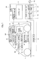
- Fig. 1 is a block diagram showing the configuration of a wireless power supply system including a parking assistance device according to this embodiment.
- the wireless power supply system includes a power supply device 100 being a ground-side unit, a power reception device 200 being vehicle-side units, and a parking assistance device 300.
- This wireless power supply system is configured to charge a battery mounted on a vehicle 1 such as an electric vehicle or a hybrid vehicle by wirelessly supplying power from the power supply device 100, which is disposed at a power supply stand or the like, to the power reception device 200, which is mounted on the vehicle 1.
- the power supply device 100 includes a ground coil 12 disposed at a parking space 2 near the power supply station.
- the power reception device 200 includes a vehicle coil 22 placed at the bottom of the vehicle 1. This vehicle coil 22 is disposed to face the ground coil 12 when the vehicle 1 stops at a predetermined position in the parking space 2.
- the ground coil 12 is formed as a primary coil made of a conductive line, and functions as a power transmission coil configured to transmit power to the vehicle coil 22, while the vehicle coil 22 is formed as a secondary coil also made of a conductive line, and functions as a power reception coil configured to receive power from the ground coil 12.
- Power can be wirelessly supplied from the ground coil 12 to the vehicle coil 22 by electromagnetic induction effect between the two coils.
- the power supply device 100 on the ground side includes a power control unit 11, the ground coil 12, a wireless communication unit 13, and a control unit 14.
- the power control unit 11 is a circuit configured to convert AC power transmitted from an AC power source 110 into high-frequency AC power and transmit it to the ground coil 12. Moreover, the power control unit 11 includes a rectification unit 111, a PFC circuit 112, and an inverter 113.
- the rectification unit 111 is a circuit electrically connected to the AC power source 110 and configured to rectify the AC power outputted from the AC power source 110.
- the PFC (Power Factor Correction) circuit 112 is a circuit configured to improve power factor by changing the waveform outputted from the rectification unit 111 into a favorable waveform, and is connected between the rectification unit 111 and the inverter 113.
- the inverter 113 includes a PWM (Power Width Modulation) control circuit constructed of switching element such as IGBTs, and is configured to convert the DC power into AC power based on switching control signals and supply the AC power to the ground coil 12.
- PWM Power Width Modulation
- the wireless communication unit 13 is configured to perform bidirectional communication with a wireless communication unit 23 provided to the vehicle 1 side.
- the control unit 14 is a part configured to control the whole power supply device 100.
- the control unit 14 controls the communication between the wireless communication units 13, 23.
- the control unit 14 transmits to the vehicle 1 side a signal indicating start of supply of power from the power supply device 100, and receives from the vehicle 1 side a signal requesting supply of power from the power supply device 100.
- the control unit 14 controls the switching of the inverter 113 and controls the power to be transmitted from the ground coil 12.
- the power reception device 200 on the vehicle 1 side includes the vehicle coil 22, the wireless communication unit 23, a charge control unit 24, a rectification unit 25, a relay unit 26, a battery 27, an inverter 28, a motor 29, and a notification unit 30.
- the vehicle coil 22 is disposed at such a position as to face the ground coil 12 from immediately above it with a predetermined value of distance to the ground coil 12 when the vehicle 1 is parked at a predetermined stop position in the parking space 2.
- the wireless communication unit 23 is configured to perform bidirectional communication with the wireless communication unit 13, which is provided to the power supply device 100.
- the charge control unit 24 is a controller for controlling the charge of the battery 27, and is configured to control components such as the wireless communication unit 23, the notification unit 30, and the relay unit 26.
- the charge control unit 24 transmits a signal indicating start of charge to the control unit 14 through communication between the wireless communication units 13, 23.
- the rectification unit 25 is connected to the vehicle coil 22, and is constructed of a rectification circuit configured to rectify the AC power received by the vehicle coil 22 into DC power.
- the relay unit 26 includes a relay switch capable of being switched on and off under control of the charge control unit 24. Moreover, by switching off the relay switch, the relay unit 26 separates a main circuit system, which includes the battery 27, and the vehicle coil 22 and the rectification unit 25, which function as a charge circuit section, from each other.
- the battery 27 is formed by connecting a plurality of secondary batteries and functions as a power source for the vehicle 1.
- the inverter 28 includes a PWM control circuit constructed of switching elements such as IGBTs, and is configured to convert DC power outputted from the battery 27 into AC power based on switching control signals and supply the AC power to the motor 29.
- a PWM control circuit constructed of switching elements such as IGBTs, and is configured to convert DC power outputted from the battery 27 into AC power based on switching control signals and supply the AC power to the motor 29.
- the motor 29 is constructed of a three-phase AC motor, for example, and functions as a drive source for driving the vehicle 1.
- the notification unit 30 is constructed of an alarm lamp, the display of a navigation system, a speaker, or the like, and is configured to output light, an image, a sound, or the like to the user based on control of the charge control unit 24.
- the wireless power supply system wirelessly transmits and receives high-frequency power through electromagnetic induction effect between the ground coil 12 and the vehicle coil 22. Specifically, by applying voltage to the ground coil 12, the ground coil 12 and the vehicle coil 22 are magnetically coupled to each other, so that power is supplied from the ground coil 12 to the vehicle coil 22.
- the parking assistance device 300 provides parking assistance in parking the vehicle 1 into the parking space 2.
- the parking assistance device 300 provides the parking assistance such that not only the positions but also the angles of the ground coil 12 and the vehicle coil 22 are aligned with each other.
- the parking assistance device 300 includes a camera 51, a display unit 53, and an image control unit 55.
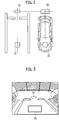
- a ground mark 57 is placed at the parking space 2. This ground mark 57 indicates the coil axis direction of the ground coil 12 and the position of the ground coil 12. The shape of the ground mark 57 will be described later in detail.
- the camera 51 is an example of an imaging unit configured to capture an image of the parking space 2 including the ground mark 57, and its height and direction have been adjusted such that it can image the ground surface. Note that this embodiment will be described by exemplarily presenting a case where the camera 51 is a back camera, but the camera 51 may be a front camera on the assumption of performing head-in parking.
- the display unit 53 is a display configured to present an image to the driver.
- the display unit 53 displays an image captured by the camera 51.
- the display unit 53 may be the display of a navigation system.
- the image control unit 55 is configured to control the image displayed on the display unit 53 during parking assistance and displays a vehicle mark in the image displayed on the display unit 53.
- This vehicle mark is an indication mark indicating the coil axis direction of the vehicle coil 22 and the position of the vehicle coil 22.
- the image control unit 55 is configured to display the vehicle mark in the image on the display unit 53 such that the vehicle mark and the ground mark 57 are superimposed on each other when the vehicle 1, on which the vehicle coil 22 is mounted, reaches a position and angle at which the vehicle 1 can be wirelessly charged.
- the image control unit 55 may be configured to display the vehicle mark in the image on the display unit 53 such that the vehicle mark and the ground mark 57 are superimposed on each other when the vehicle 1 reaches a position and angle at which the wireless charge is at the maximum charge efficiency.
- the parking assistance device 300 is constructed of general-purpose electronic circuits including a microcomputer, a microprocessor or a CPU, and peripheral instruments, and operates as the image control unit 55 by executing a particular program.
- the ground mark 57 is placed at the back of the parking space 2. This position is a position on the center line of the ground coil 12 and is also a position from which the ground mark 57 can be imaged by the camera 51 when the vehicle 1 is parked at a position at which the vehicle 1 can be wirelessly charged.
- a vehicle mark 59 is present at a position on the center line of the vehicle coil 22 on the image displayed on the display unit 53, and is displayed at such a position as to be superimposed on the ground mark 57 when the vehicle 1 reaches a position and angle at which the vehicle 1 can be wirelessly charged.
- the image control unit 55 displays a track prediction line L predicting the track of the vehicle mark 59 on the image of the display unit 53 as shown in Fig. 4 , and changes the track prediction line L in accordance with change in steering angle of the vehicle 1 by acquiring the steering angle from the steering angle sensor of the vehicle 1.
- the image control unit 55 may detect change in coil-to-coil distance between the ground coil 12 and the vehicle coil 22 from change in attitude of the vehicle 1, and correct the position and shape of the vehicle mark 59 in accordance with the change in coil-to-coil distance.
- the image control unit 55 acquires a value detected by a pneumatic sensor, a stroke sensor, a height sensor, or the like mounted on the vehicle 1, and determines whether or not the number of occupants and/or the loaded state has changed the attitude of the vehicle 1 and accordingly changed the coil-to-coil distance. If the coil-to-coil distance has been changed, the image control unit 55 corrects the position and shape of the vehicle mark 59 in accordance with the change in coil-to-coil distance.
- a criterial suspension stroke is stored in the image control unit 55 in advance and, upon change in suspension stroke caused by sinking of the vehicle by an item(s) or an occupant(s), the image control unit 55 estimates the change in coil-to-coil distance from the change in suspension stroke. Then, the image control unit 55 corrects the position and size of the vehicle mark 59 by changing the position and the size of the vehicle mark 59 in accordance with the change in coil-to-coil distance.
- the driver can park the vehicle 1 at a position and angle at which the vehicle 1 can be wirelessly charged. Also, by parking the vehicle 1 in such a way as to superimpose the ground mark 57 and the vehicle mark 59 on each other, the driver can park the vehicle 1 at a position and angle at which the wireless charge is at the maximum charge efficiency.
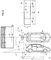
- a point 60 at which a field of view S of the camera 51 crosses a ground surface G is the bottom edge of the angle of view of the camera 51 and is the bottom edge of the displayed image.
- a point at which the bottom edge of this angle of view and the center line of the vehicle 1 cross each other is a first origin 63, and a point on the center line of the vehicle 1 at a predetermined distance A from this first origin 63 is a second origin 65. Note that, in a case where the center of the vehicle 1 and the center of the vehicle coil 22 are offset from each other, the positions of the first and second origins 63, 65 are corrected in accordance with the position of the vehicle coil 22.
- the ground mark 57 which has a line segment shape centered at the second origin 65 and having a length of a in the vehicle width direction of the vehicle 1 and a width of b in the front-rear direction of the vehicle 1, is placed at the parking space 2.
- a may be equal to 200 mm
- b may be equal to 100 mm, for example.
- the vehicle mark 59 has a line segment shape centered at the second origin 65 and having a length of 2a in the vehicle width direction of the vehicle 1 and a width of b in the front-rear direction of the vehicle 1 as shown in Part (b) of Fig. 6 , and this line segment shape is displayed with its size converted into a size on the image.
- the shape of the vehicle mark 59 has a length of 400 mm in the vehicle width direction of the vehicle 1 and a width of 100 mm in the front-rear direction of the vehicle 1.
- the vehicle mark 59 is longer than the ground mark 57 in Fig. 6 , but the ground mark 57 may be longer.
- the line segment shape of the vehicle mark 59 indicates the direction of the coil axis of the vehicle coil 22.
- a coil axis 73 of the vehicle coil 22 is oriented in the front-rear direction of the vehicle, and a magnetic flux 75 is generated in the front-rear direction of the vehicle as well.
- the line segment shape of the vehicle mark 59 is displayed long in a direction perpendicular to the coil axis 73 and thus indicates the direction of the coil axis 73.
- the coil axis 73 is oriented in the vehicle width direction.
- the line segment shape of the vehicle mark 59 is displayed long in the direction parallel to the coil axis 73 and indicates the direction of the coil axis 73.
- the line segment shape of the ground mark 57 is placed in such a way as to indicate the direction of a coil axis 77 of the ground coil 12.
- the line segment shape of the ground mark 57 is displayed long in a direction perpendicular to the coil axis 77 and thus indicates the direction of the coil axis 77.
- the line segment shape of the ground mark 57 is displayed long in the direction parallel to the coil axis 77 and indicates the direction of the coil axis 77.
- the driver can bring the direction of the coil axis of the ground coil 12 and the direction of the coil axis of the vehicle coil 22 into coincidence with each other by superimposing the ground mark 57 and the vehicle mark 59 on each other on the image.
- the magnetic flux generated from the ground coil 12 penetrates the vehicle coil 22 in the direction of its coil axis.
- the efficiency of charge from the ground coil 12 to the vehicle coil 22 can be improved.
- the driver can accurately align the angles and also positions of the ground coil 12 and the vehicle coil 22 with each other.
- the location to place the ground mark 57 is not limited to the ground surface G of the parking space 2 shown in Part (a) of Fig. 8 .
- the ground mark 57 may be on a sidewalk 81.
- the ground mark 57 may be placed on a wall or pole 83 provided at the parking space 2, or the ground mark 57 may be placed on a fence 85 shown in Part (d) of Fig. 8 .
- the ground mark 57 indicating the coil axis direction and position of the ground coil 12
- the vehicle mark 59 indicating the coil axis direction and position of the vehicle coil 22
- the parking assistance device 300 displays the image such that the vehicle mark 59 is superimposed on the ground mark 57 when the vehicle reaches a position and angle at which the vehicle can be wirelessly charged.
- the driver can accurately align not only the positions but also the angles of the ground coil 12 and vehicle coil 22 with each other by parking in such a way as to superimpose the ground mark 57 and the vehicle mark 59 on each other on the image displayed on the display unit 53.
- solenoid type coils are used as the ground coil 12 and the vehicle coil 22.
- the ground mark 57 has the shape of a line segment indicating the coil axis direction of the ground coil 12.
- the vehicle mark 59 has the shape of a line segment indicating the coil axis direction of the vehicle coil 22.
- change in coil-to-coil distance between the ground coil 12 and the vehicle coil 22 is detected from change in attitude of the vehicle 1, and the position and shape of the vehicle mark 59 are corrected in accordance with the change in coil-to-coil distance.
- the positions and angles of the ground coil 12 and the vehicle coil 22 can be accurately aligned with each other.
- the track prediction line L predicting the track of the vehicle mark 59
- the track prediction line L is displayed on the image, and the track prediction line L is changed in accordance with the steering angle of the vehicle 1.
- a parking assistance device according to a second embodiment of the present invention will be described with reference to a drawing. Note that the configurations of a wireless power supply system and the parking assistance device in this embodiment are the same as those in the first embodiment, and detailed description will therefore be omitted.
- the parking assistance device 300 differs from that in the first embodiment in the shape of the vehicle mark.
- the vehicle mark has the shape of a line segment indicating the direction of the coil axis of the vehicle coil 22.
- the vehicle mark in addition to the shape of a line segment indicating the direction of the coil axis of the vehicle coil 22, has a width corresponding to a range within which a predetermined charge efficiency can be achieved.
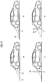
- the ground mark 57 has a line segment shape centered at the second origin 65 and having a length of a in the vehicle width direction of the vehicle 1 and a width of b in the front-rear direction of the vehicle 1, as in the first embodiment.
- a is equal to 200 mm
- b is equal to 100 mm, for example.
- a vehicle mark 91 has a line segment shape centered at the second origin 65 and having a length of 2a in the vehicle width direction of the vehicle 1 and a width of 2b in the front-rear direction of the vehicle 1, and this line segment shape is displayed with its size converted into a size on the image.
- the shape of the vehicle mark 91 has a length of 400 mm in the vehicle width direction of the vehicle 1 and a width of 200 mm in the front-rear direction of the vehicle 1.
- the width of the vehicle mark 91 is widened by b/2 to the front and to the rear and hence widened by b in total.
- This width of b by which the vehicle mark 91 is widened corresponds to the range within which the predetermined charge efficiency can be achieved.
- the required predetermined charge efficiency is set in advance.
- the angle formed between the ground coil 12 and the vehicle coil 22 needs to be at or below a predetermined value.
- the ground mark 57 is turned by the predetermined angle at and below which the predetermined charge efficiency can be achieved, e.g. 30 degrees, and the width of the vehicle mark 91 is set such that the ground mark 57 thus turned can be within the vehicle mark 91.
- the width of the vehicle mark 91 corresponds to the range within which the predetermined charge efficiency can be achieved. Note that the vehicle mark 91 is larger than the ground mark 57 in Fig. 9 , but the ground mark 57 may be larger.
- the vehicle mark 91 has a width corresponding to the range within which the predetermined charge efficiency can be achieved.
- the driver can ensure the required predetermined charge efficiency by parking in such a way as to position the ground mark 57 within the vehicle mark 91.
Landscapes
- Engineering & Computer Science (AREA)
- Power Engineering (AREA)
- Mechanical Engineering (AREA)
- Transportation (AREA)
- Multimedia (AREA)
- Computer Networks & Wireless Communication (AREA)
- Signal Processing (AREA)
- Sustainable Development (AREA)
- Life Sciences & Earth Sciences (AREA)
- Sustainable Energy (AREA)
- Physics & Mathematics (AREA)
- General Physics & Mathematics (AREA)
- Theoretical Computer Science (AREA)
- Electric Propulsion And Braking For Vehicles (AREA)
- Traffic Control Systems (AREA)
- Charge And Discharge Circuits For Batteries Or The Like (AREA)
- Current-Collector Devices For Electrically Propelled Vehicles (AREA)
Claims (6)
- Dispositif d'assistance au stationnement (300) pour fournir une assistance au stationnement en vue de garer un véhicule (1) dans un espace de stationnement (2) avec une bobine au sol (12) placée au niveau de l'espace de stationnement (2), la bobine au sol (12) étant configurée pour distribuer sans fil de l'énergie à une bobine de véhicule (22) montée sur le véhicule (1), où :- une marque au sol (57) indiquant une direction d'axe de bobine de la bobine au sol (12) et une position de la bobine au sol (12) et ayant une forme d'un segment de ligne indiquant la direction d'axe de bobine de la bobine au sol (12) est placée au niveau de l'espace de stationnement (2),- le dispositif d'assistance au stationnement (300) comprend- une unité d'imagerie (51) configurée pour capturer une image de l'espace de stationnement (2) comportant la marque au sol (57),- une unité d'affichage (53) configurée pour afficher l'image capturée par l'unité d'imagerie (51),- une unité de commande d'image (55) configurée pour afficher une marque de véhicule (59) dans l'image affichée sur l'unité d'affichage (53), la marque de véhicule (59) indiquant une direction d'axe de bobine de la bobine de véhicule (22) et une position de la bobine de véhicule (22) et ayant une forme d'un segment de ligne indiquant la direction d'axe de bobine de la bobine de véhicule (22), et- l'unité de commande d'image (55) est configurée pour afficher la marque de véhicule (59) dans l'image de sorte que la marque de véhicule (59) et la marque au sol (57) soient superposées l'une sur l'autre, lorsque le véhicule (1) sur lequel la bobine de véhicule (22) est montée atteint une position et un angle auxquels le véhicule (1) peut être chargé sans fil.
- Dispositif d'assistance au stationnement (300) selon la revendication 1, dans lequel la bobine de véhicule (22) et la bobine au sol (12) sont des bobines de type solénoïde.
- Dispositif d'assistance au stationnement (300) selon la revendication 2, dans lequel la marque de véhicule (91) a une largeur correspondant à une plage dans laquelle une efficacité de charge prédéterminée peut être obtenue.
- Dispositif d'assistance au stationnement (300) selon l'une quelconque des revendications 1 à 3, dans lequel l'unité de commande d'image (55) est configurée- pour détecter un changement de la distance bobine-à-bobine entre la bobine au sol (12) et la bobine de véhicule (22) à partir d'un changement de l'assiette du véhicule (1) sur lequel la bobine de véhicule (22) est montée, et- pour corriger une position et une forme de la marque de véhicule (59) conformément au changement de la distance bobine-à-bobine.
- Dispositif d'assistance au stationnement (300) selon l'une quelconque des revendications 1 à 4, dans lequel l'unité de commande d'image (55) est configurée- pour afficher une ligne de prédiction de piste (L) sur l'image et- pour changer la ligne de prédiction de piste (L) conformément à un angle de direction du véhicule (1) sur lequel la bobine de véhicule (22) est montée, la ligne de prédiction de piste (L) prédisant une piste de la marque de véhicule (59).
- Procédé d'assistance au stationnement en vue de garer un véhicule (1) dans un espace de stationnement (2), avec une bobine au sol (12) placée au niveau de l'espace de stationnement (2), la bobine au sol (12) étant configurée pour distribuer sans fil de l'énergie à une bobine de véhicule (22) montée sur le véhicule (1), comprenant le fait :- de placer une marque au sol (57) au niveau de l'espace de stationnement (2), la marque au sol (57) indiquant une direction d'axe de bobine de la bobine au sol (12) et une position de la bobine au sol (12) et ayant une forme d'un segment de ligne indiquant la direction d'axe de bobine de la bobine au sol (12) ;- de capturer une image de l'espace de stationnement (2) comportant la marque au sol (57) en utilisant une unité d'imagerie (51) ;- d'afficher l'image capturée par l'unité d'imagerie (51) sur une unité d'affichage (53), et- de réaliser un processus de commande d'image qui affiche une marque de véhicule (59) dans l'image affichée sur l'unité d'affichage (53), la marque de véhicule (59) indiquant une direction d'axe de bobine de la bobine de véhicule (22) et une position de la bobine de véhicule (22) et ayant une forme d'un segment de ligne indiquant la direction d'axe de bobine de la bobine de véhicule (22) ; et- le processus de commande d'image affiche la marque de véhicule (59) dans l'image de sorte que la marque de véhicule (59) et la marque au sol (57) soient superposées l'une sur l'autre, lorsque le véhicule (1) sur lequel la bobine de véhicule (22) est montée atteint une position et un angle auxquels le véhicule (1) peut être chargé sans fil.
Applications Claiming Priority (1)
| Application Number | Priority Date | Filing Date | Title |
|---|---|---|---|
| PCT/JP2014/052128 WO2015114782A1 (fr) | 2014-01-30 | 2014-01-30 | Dispositif d'assistance au stationnement et méthode d'assistance au stationnement |
Publications (3)
| Publication Number | Publication Date |
|---|---|
| EP3103673A1 EP3103673A1 (fr) | 2016-12-14 |
| EP3103673A4 EP3103673A4 (fr) | 2017-03-01 |
| EP3103673B1 true EP3103673B1 (fr) | 2018-03-14 |
Family
ID=53756394
Family Applications (1)
| Application Number | Title | Priority Date | Filing Date |
|---|---|---|---|
| EP14880931.2A Active EP3103673B1 (fr) | 2014-01-30 | 2014-01-30 | Dispositif d'assistance au stationnement et méthode d'assistance au stationnement |
Country Status (4)
| Country | Link |
|---|---|
| US (1) | US9956914B2 (fr) |
| EP (1) | EP3103673B1 (fr) |
| JP (1) | JP6168164B2 (fr) |
| WO (1) | WO2015114782A1 (fr) |
Cited By (1)
| Publication number | Priority date | Publication date | Assignee | Title |
|---|---|---|---|---|
| WO2021092726A1 (fr) * | 2019-11-11 | 2021-05-20 | 威刚科技股份有限公司 | Véhicule automoteur et système de véhicule automoteur |
Families Citing this family (14)
| Publication number | Priority date | Publication date | Assignee | Title |
|---|---|---|---|---|
| JP6043462B2 (ja) * | 2012-09-27 | 2016-12-14 | Ihi運搬機械株式会社 | 車両給電装置 |
| JP6119868B2 (ja) * | 2013-09-30 | 2017-04-26 | 日産自動車株式会社 | 非接触給電装置及び駐車支援装置 |
| KR102066334B1 (ko) * | 2015-04-07 | 2020-01-14 | 닛산 지도우샤 가부시키가이샤 | 주차 지원 시스템 및 주차 지원 장치 |
| CN105882549A (zh) * | 2015-11-02 | 2016-08-24 | 乐卡汽车智能科技(北京)有限公司 | 控制车辆上全景摄像头俯角的方法和车载设备 |
| US10683035B2 (en) | 2015-12-08 | 2020-06-16 | Panasonic Intellectual Property Management Co., Ltd. | Parking assistance device, parking assistance method, and non-transitory computer readable medium |
| JP6637836B2 (ja) * | 2016-05-12 | 2020-01-29 | 株式会社ダイヘン | 送電装置、受電装置、および、非接触充電システム |
| RU2719089C1 (ru) * | 2016-05-18 | 2020-04-17 | Ниссан Мотор Ко., Лтд. | Устройство помощи при парковке и способ помощи при парковке |
| EP3263405B1 (fr) * | 2016-06-27 | 2019-08-07 | Volvo Car Corporation | Système de surveillance de vue alentour et procédé pour véhicules |
| DE102017130173A1 (de) * | 2017-02-24 | 2018-08-30 | Denso Ten Limited | Ladeunterstützungsvorrichtung |
| DE102017206528A1 (de) * | 2017-04-18 | 2018-10-31 | Bayerische Motoren Werke Aktiengesellschaft | Fahrzeugpositionierung für induktive Energieübertragung |
| DE102017206530A1 (de) * | 2017-04-18 | 2018-10-18 | Bayerische Motoren Werke Aktiengesellschaft | Fahrzeugpositionierung für induktive Energieübertragung |
| JP7312966B2 (ja) * | 2019-11-28 | 2023-07-24 | パナソニックIpマネジメント株式会社 | 駐車支援装置、車両、駐車支援方法、プログラム、および非一時的記録媒体 |
| JP7015338B2 (ja) | 2020-03-16 | 2022-02-02 | 本田技研工業株式会社 | 駐車支援装置 |
| CN112597917B (zh) * | 2020-12-25 | 2022-09-30 | 太原理工大学 | 一种基于深度学习的车辆停车检测方法 |
Family Cites Families (27)
| Publication number | Priority date | Publication date | Assignee | Title |
|---|---|---|---|---|
| US2074251A (en) | 1935-01-11 | 1937-03-16 | Braun August Wilhelm | Arrangement for the automatic steering of motor vehicles |
| JPS61193210A (ja) | 1985-02-21 | 1986-08-27 | Toshiba Corp | 無人搬送車の搬送制御方式 |
| US6341430B1 (en) | 2000-03-24 | 2002-01-29 | Honda Of America Mfg., Inc. | Automated guidance vehicle guide path code templates and methods for use |
| JP2003182489A (ja) | 2001-12-19 | 2003-07-03 | Matsushita Electric Ind Co Ltd | 駐車支援装置 |
| CN101573257B (zh) | 2006-12-28 | 2011-08-10 | 株式会社丰田自动织机 | 停车辅助装置及方法、行车参数的计算方法及装置 |
| JP4853712B2 (ja) * | 2006-12-28 | 2012-01-11 | アイシン精機株式会社 | 駐車支援装置 |
| WO2009016925A1 (fr) | 2007-07-31 | 2009-02-05 | Kabushiki Kaisha Toyota Jidoshokki | Dispositif d'aide au stationnement, dispositif côté véhicule pour dispositif d'aide au stationnement, procédé et programme d'aide au stationnement |
| JP2010149723A (ja) | 2008-12-25 | 2010-07-08 | Toyota Industries Corp | 駐車支援装置 |
| WO2010098397A1 (fr) * | 2009-02-25 | 2010-09-02 | マスプロ電工株式会社 | Système d'alimentation électrique pour unité mobile |
| JP5404095B2 (ja) | 2009-02-26 | 2014-01-29 | トヨタホーム株式会社 | 駐車設備 |
| JP5177433B2 (ja) * | 2009-03-30 | 2013-04-03 | アイシン・エィ・ダブリュ株式会社 | 受電案内装置、受電案内方法、及び受電案内プログラム |
| JP5377119B2 (ja) | 2009-07-02 | 2013-12-25 | トヨタ自動車株式会社 | 駐車支援システムおよび駐車支援システムの制御方法 |
| JP5504009B2 (ja) * | 2010-03-03 | 2014-05-28 | 本田技研工業株式会社 | 電気自動車 |
| WO2011146661A2 (fr) | 2010-05-19 | 2011-11-24 | Qualcomm Incorporated | Système de transfert d'énergie sans fil adaptatif |
| JP2012138976A (ja) * | 2010-12-24 | 2012-07-19 | Equos Research Co Ltd | 電力伝送システム |
| US9178369B2 (en) | 2011-01-18 | 2015-11-03 | Mojo Mobility, Inc. | Systems and methods for providing positioning freedom, and support of different voltages, protocols, and power levels in a wireless power system |
| JP2012208599A (ja) * | 2011-03-29 | 2012-10-25 | Panasonic Corp | 駐車支援装置 |
| JP5789768B2 (ja) | 2011-03-30 | 2015-10-07 | パナソニックIpマネジメント株式会社 | 車載用表示装置 |
| US20130037339A1 (en) | 2011-08-12 | 2013-02-14 | Delphi Technologies, Inc. | Parking assist for a vehicle equipped with for wireless vehicle charging |
| JP2013046482A (ja) | 2011-08-24 | 2013-03-04 | Panasonic Corp | 給電装置への誘導装置、及びそれを用いた車両充電位置自動駐車制御システム |
| US8483899B2 (en) | 2011-10-06 | 2013-07-09 | Ford Global Technologies, Llc | Vehicle guidance system |
| DE102012003992A1 (de) * | 2012-02-28 | 2013-08-29 | Wabco Gmbh | Zielführungssystem für Kraftfahrzeuge |
| JP6065394B2 (ja) | 2012-03-14 | 2017-01-25 | 株式会社Ihi | 移動車両給電システム及び移動車両 |
| WO2013146139A1 (fr) * | 2012-03-28 | 2013-10-03 | 日産自動車株式会社 | Système d'aide au stationnement et procédé d'aide au stationnement |
| JP5591283B2 (ja) * | 2012-06-14 | 2014-09-17 | トヨタ自動車株式会社 | 非接触送電装置、非接触受電装置、および非接触送受電システム |
| DE102012015262A1 (de) * | 2012-08-01 | 2014-02-06 | Audi Ag | Verfahren zum Positionieren eines Kraftwagens, System mit einem solchen Kraftwagen sowie Kraftwagen |
| US10391938B2 (en) * | 2015-05-15 | 2019-08-27 | Ford Global Technologies, Llc | Imaging system for locating a moving object in relation to another object |
-
2014
- 2014-01-30 US US15/111,259 patent/US9956914B2/en active Active
- 2014-01-30 JP JP2015559678A patent/JP6168164B2/ja active Active
- 2014-01-30 EP EP14880931.2A patent/EP3103673B1/fr active Active
- 2014-01-30 WO PCT/JP2014/052128 patent/WO2015114782A1/fr active Application Filing
Non-Patent Citations (1)
| Title |
|---|
| None * |
Cited By (1)
| Publication number | Priority date | Publication date | Assignee | Title |
|---|---|---|---|---|
| WO2021092726A1 (fr) * | 2019-11-11 | 2021-05-20 | 威刚科技股份有限公司 | Véhicule automoteur et système de véhicule automoteur |
Also Published As
| Publication number | Publication date |
|---|---|
| US20160332575A1 (en) | 2016-11-17 |
| JPWO2015114782A1 (ja) | 2017-03-23 |
| JP6168164B2 (ja) | 2017-07-26 |
| US9956914B2 (en) | 2018-05-01 |
| EP3103673A1 (fr) | 2016-12-14 |
| WO2015114782A1 (fr) | 2015-08-06 |
| EP3103673A4 (fr) | 2017-03-01 |
Similar Documents
| Publication | Publication Date | Title |
|---|---|---|
| EP3103673B1 (fr) | Dispositif d'assistance au stationnement et méthode d'assistance au stationnement | |
| US10562396B2 (en) | Parking assistance apparatus and system | |
| KR101860245B1 (ko) | 주차 지원 장치 및 주차 지원 방법 | |
| US9199547B2 (en) | Non-contact charging device | |
| US10967745B2 (en) | Parking assistance method and parking assistance device | |
| WO2015097995A1 (fr) | Dispositif de réception de puissance et véhicule le comprenant | |
| JP6090333B2 (ja) | 非接触給電装置、非接触給電システム及び非接触給電方法 | |
| US20150336464A1 (en) | Ultrasonic location for electric vehicle charging system | |
| CN108928248B (zh) | 非接触电功率传输系统 | |
| US20160033288A1 (en) | Vehicle power-supplying system | |
| KR102066334B1 (ko) | 주차 지원 시스템 및 주차 지원 장치 | |
| JP5966407B2 (ja) | 移動車両及び非接触電力伝送装置 | |
| JP5966332B2 (ja) | 移動車両及び非接触電力伝送装置 | |
| JP2013153564A (ja) | 移動車両給電システム | |
| CN109314409B (zh) | 非接触供电系统的线圈位置检测方法和非接触供电系统 | |
| WO2014054608A1 (fr) | Dispositif d'alimentation en énergie sans contact | |
| JPWO2014156656A1 (ja) | 電気自動車及び電気自動車の駐車支援システム |
Legal Events
| Date | Code | Title | Description |
|---|---|---|---|
| STAA | Information on the status of an ep patent application or granted ep patent |
Free format text: STATUS: THE INTERNATIONAL PUBLICATION HAS BEEN MADE |
|
| PUAI | Public reference made under article 153(3) epc to a published international application that has entered the european phase |
Free format text: ORIGINAL CODE: 0009012 |
|
| STAA | Information on the status of an ep patent application or granted ep patent |
Free format text: STATUS: REQUEST FOR EXAMINATION WAS MADE |
|
| 17P | Request for examination filed |
Effective date: 20160802 |
|
| AK | Designated contracting states |
Kind code of ref document: A1 Designated state(s): AL AT BE BG CH CY CZ DE DK EE ES FI FR GB GR HR HU IE IS IT LI LT LU LV MC MK MT NL NO PL PT RO RS SE SI SK SM TR |
|
| AX | Request for extension of the european patent |
Extension state: BA ME |
|
| A4 | Supplementary search report drawn up and despatched |
Effective date: 20170131 |
|
| RIC1 | Information provided on ipc code assigned before grant |
Ipc: H04N 5/232 20060101ALI20170125BHEP Ipc: H04N 7/18 20060101ALI20170125BHEP Ipc: B60L 3/00 20060101ALI20170125BHEP Ipc: H02J 7/00 20060101ALI20170125BHEP Ipc: H02J 7/02 20160101ALI20170125BHEP Ipc: G06K 9/00 20060101ALI20170125BHEP Ipc: B60R 1/00 20060101ALI20170125BHEP Ipc: H01F 38/14 20060101ALI20170125BHEP Ipc: B60L 11/18 20060101AFI20170125BHEP |
|
| DAX | Request for extension of the european patent (deleted) | ||
| GRAP | Despatch of communication of intention to grant a patent |
Free format text: ORIGINAL CODE: EPIDOSNIGR1 |
|
| STAA | Information on the status of an ep patent application or granted ep patent |
Free format text: STATUS: GRANT OF PATENT IS INTENDED |
|
| RIC1 | Information provided on ipc code assigned before grant |
Ipc: H04N 5/232 20060101ALI20171009BHEP Ipc: B60L 3/00 20060101ALI20171009BHEP Ipc: H02J 7/00 20060101ALI20171009BHEP Ipc: H01F 38/14 20060101ALI20171009BHEP Ipc: H04N 7/18 20060101ALI20171009BHEP Ipc: B60R 1/00 20060101ALI20171009BHEP Ipc: B60L 11/18 20060101AFI20171009BHEP Ipc: H02J 7/02 20160101ALI20171009BHEP Ipc: G06K 9/00 20060101ALI20171009BHEP |
|
| INTG | Intention to grant announced |
Effective date: 20171109 |
|
| GRAS | Grant fee paid |
Free format text: ORIGINAL CODE: EPIDOSNIGR3 |
|
| GRAA | (expected) grant |
Free format text: ORIGINAL CODE: 0009210 |
|
| STAA | Information on the status of an ep patent application or granted ep patent |
Free format text: STATUS: THE PATENT HAS BEEN GRANTED |
|
| AK | Designated contracting states |
Kind code of ref document: B1 Designated state(s): AL AT BE BG CH CY CZ DE DK EE ES FI FR GB GR HR HU IE IS IT LI LT LU LV MC MK MT NL NO PL PT RO RS SE SI SK SM TR |
|
| REG | Reference to a national code |
Ref country code: GB Ref legal event code: FG4D |
|
| REG | Reference to a national code |
Ref country code: CH Ref legal event code: EP Ref country code: AT Ref legal event code: REF Ref document number: 978519 Country of ref document: AT Kind code of ref document: T Effective date: 20180315 |
|
| REG | Reference to a national code |
Ref country code: IE Ref legal event code: FG4D |
|
| REG | Reference to a national code |
Ref country code: DE Ref legal event code: R096 Ref document number: 602014022462 Country of ref document: DE |
|
| REG | Reference to a national code |
Ref country code: NL Ref legal event code: MP Effective date: 20180314 |
|
| REG | Reference to a national code |
Ref country code: LT Ref legal event code: MG4D |
|
| PG25 | Lapsed in a contracting state [announced via postgrant information from national office to epo] |
Ref country code: NO Free format text: LAPSE BECAUSE OF FAILURE TO SUBMIT A TRANSLATION OF THE DESCRIPTION OR TO PAY THE FEE WITHIN THE PRESCRIBED TIME-LIMIT Effective date: 20180614 Ref country code: CY Free format text: LAPSE BECAUSE OF FAILURE TO SUBMIT A TRANSLATION OF THE DESCRIPTION OR TO PAY THE FEE WITHIN THE PRESCRIBED TIME-LIMIT Effective date: 20180314 Ref country code: HR Free format text: LAPSE BECAUSE OF FAILURE TO SUBMIT A TRANSLATION OF THE DESCRIPTION OR TO PAY THE FEE WITHIN THE PRESCRIBED TIME-LIMIT Effective date: 20180314 Ref country code: LT Free format text: LAPSE BECAUSE OF FAILURE TO SUBMIT A TRANSLATION OF THE DESCRIPTION OR TO PAY THE FEE WITHIN THE PRESCRIBED TIME-LIMIT Effective date: 20180314 Ref country code: FI Free format text: LAPSE BECAUSE OF FAILURE TO SUBMIT A TRANSLATION OF THE DESCRIPTION OR TO PAY THE FEE WITHIN THE PRESCRIBED TIME-LIMIT Effective date: 20180314 |
|
| REG | Reference to a national code |
Ref country code: AT Ref legal event code: MK05 Ref document number: 978519 Country of ref document: AT Kind code of ref document: T Effective date: 20180314 |
|
| PG25 | Lapsed in a contracting state [announced via postgrant information from national office to epo] |
Ref country code: RS Free format text: LAPSE BECAUSE OF FAILURE TO SUBMIT A TRANSLATION OF THE DESCRIPTION OR TO PAY THE FEE WITHIN THE PRESCRIBED TIME-LIMIT Effective date: 20180314 Ref country code: GR Free format text: LAPSE BECAUSE OF FAILURE TO SUBMIT A TRANSLATION OF THE DESCRIPTION OR TO PAY THE FEE WITHIN THE PRESCRIBED TIME-LIMIT Effective date: 20180615 Ref country code: BG Free format text: LAPSE BECAUSE OF FAILURE TO SUBMIT A TRANSLATION OF THE DESCRIPTION OR TO PAY THE FEE WITHIN THE PRESCRIBED TIME-LIMIT Effective date: 20180614 Ref country code: LV Free format text: LAPSE BECAUSE OF FAILURE TO SUBMIT A TRANSLATION OF THE DESCRIPTION OR TO PAY THE FEE WITHIN THE PRESCRIBED TIME-LIMIT Effective date: 20180314 Ref country code: SE Free format text: LAPSE BECAUSE OF FAILURE TO SUBMIT A TRANSLATION OF THE DESCRIPTION OR TO PAY THE FEE WITHIN THE PRESCRIBED TIME-LIMIT Effective date: 20180314 |
|
| PG25 | Lapsed in a contracting state [announced via postgrant information from national office to epo] |
Ref country code: NL Free format text: LAPSE BECAUSE OF FAILURE TO SUBMIT A TRANSLATION OF THE DESCRIPTION OR TO PAY THE FEE WITHIN THE PRESCRIBED TIME-LIMIT Effective date: 20180314 Ref country code: ES Free format text: LAPSE BECAUSE OF FAILURE TO SUBMIT A TRANSLATION OF THE DESCRIPTION OR TO PAY THE FEE WITHIN THE PRESCRIBED TIME-LIMIT Effective date: 20180314 Ref country code: PL Free format text: LAPSE BECAUSE OF FAILURE TO SUBMIT A TRANSLATION OF THE DESCRIPTION OR TO PAY THE FEE WITHIN THE PRESCRIBED TIME-LIMIT Effective date: 20180314 Ref country code: AL Free format text: LAPSE BECAUSE OF FAILURE TO SUBMIT A TRANSLATION OF THE DESCRIPTION OR TO PAY THE FEE WITHIN THE PRESCRIBED TIME-LIMIT Effective date: 20180314 Ref country code: RO Free format text: LAPSE BECAUSE OF FAILURE TO SUBMIT A TRANSLATION OF THE DESCRIPTION OR TO PAY THE FEE WITHIN THE PRESCRIBED TIME-LIMIT Effective date: 20180314 Ref country code: EE Free format text: LAPSE BECAUSE OF FAILURE TO SUBMIT A TRANSLATION OF THE DESCRIPTION OR TO PAY THE FEE WITHIN THE PRESCRIBED TIME-LIMIT Effective date: 20180314 |
|
| PG25 | Lapsed in a contracting state [announced via postgrant information from national office to epo] |
Ref country code: CZ Free format text: LAPSE BECAUSE OF FAILURE TO SUBMIT A TRANSLATION OF THE DESCRIPTION OR TO PAY THE FEE WITHIN THE PRESCRIBED TIME-LIMIT Effective date: 20180314 Ref country code: SM Free format text: LAPSE BECAUSE OF FAILURE TO SUBMIT A TRANSLATION OF THE DESCRIPTION OR TO PAY THE FEE WITHIN THE PRESCRIBED TIME-LIMIT Effective date: 20180314 Ref country code: AT Free format text: LAPSE BECAUSE OF FAILURE TO SUBMIT A TRANSLATION OF THE DESCRIPTION OR TO PAY THE FEE WITHIN THE PRESCRIBED TIME-LIMIT Effective date: 20180314 Ref country code: SK Free format text: LAPSE BECAUSE OF FAILURE TO SUBMIT A TRANSLATION OF THE DESCRIPTION OR TO PAY THE FEE WITHIN THE PRESCRIBED TIME-LIMIT Effective date: 20180314 |
|
| REG | Reference to a national code |
Ref country code: DE Ref legal event code: R097 Ref document number: 602014022462 Country of ref document: DE |
|
| PG25 | Lapsed in a contracting state [announced via postgrant information from national office to epo] |
Ref country code: PT Free format text: LAPSE BECAUSE OF FAILURE TO SUBMIT A TRANSLATION OF THE DESCRIPTION OR TO PAY THE FEE WITHIN THE PRESCRIBED TIME-LIMIT Effective date: 20180716 |
|
| REG | Reference to a national code |
Ref country code: DE Ref legal event code: R079 Ref document number: 602014022462 Country of ref document: DE Free format text: PREVIOUS MAIN CLASS: B60L0011180000 Ipc: B60L0050500000 |
|
| PLBE | No opposition filed within time limit |
Free format text: ORIGINAL CODE: 0009261 |
|
| STAA | Information on the status of an ep patent application or granted ep patent |
Free format text: STATUS: NO OPPOSITION FILED WITHIN TIME LIMIT |
|
| PG25 | Lapsed in a contracting state [announced via postgrant information from national office to epo] |
Ref country code: DK Free format text: LAPSE BECAUSE OF FAILURE TO SUBMIT A TRANSLATION OF THE DESCRIPTION OR TO PAY THE FEE WITHIN THE PRESCRIBED TIME-LIMIT Effective date: 20180314 |
|
| 26N | No opposition filed |
Effective date: 20181217 |
|
| PG25 | Lapsed in a contracting state [announced via postgrant information from national office to epo] |
Ref country code: SI Free format text: LAPSE BECAUSE OF FAILURE TO SUBMIT A TRANSLATION OF THE DESCRIPTION OR TO PAY THE FEE WITHIN THE PRESCRIBED TIME-LIMIT Effective date: 20180314 Ref country code: IT Free format text: LAPSE BECAUSE OF FAILURE TO SUBMIT A TRANSLATION OF THE DESCRIPTION OR TO PAY THE FEE WITHIN THE PRESCRIBED TIME-LIMIT Effective date: 20180314 |
|
| PG25 | Lapsed in a contracting state [announced via postgrant information from national office to epo] |
Ref country code: MC Free format text: LAPSE BECAUSE OF FAILURE TO SUBMIT A TRANSLATION OF THE DESCRIPTION OR TO PAY THE FEE WITHIN THE PRESCRIBED TIME-LIMIT Effective date: 20180314 |
|
| REG | Reference to a national code |
Ref country code: CH Ref legal event code: PL |
|
| PG25 | Lapsed in a contracting state [announced via postgrant information from national office to epo] |
Ref country code: LU Free format text: LAPSE BECAUSE OF NON-PAYMENT OF DUE FEES Effective date: 20190130 |
|
| REG | Reference to a national code |
Ref country code: BE Ref legal event code: MM Effective date: 20190131 |
|
| REG | Reference to a national code |
Ref country code: IE Ref legal event code: MM4A |
|
| PG25 | Lapsed in a contracting state [announced via postgrant information from national office to epo] |
Ref country code: BE Free format text: LAPSE BECAUSE OF NON-PAYMENT OF DUE FEES Effective date: 20190131 |
|
| PG25 | Lapsed in a contracting state [announced via postgrant information from national office to epo] |
Ref country code: CH Free format text: LAPSE BECAUSE OF NON-PAYMENT OF DUE FEES Effective date: 20190131 Ref country code: LI Free format text: LAPSE BECAUSE OF NON-PAYMENT OF DUE FEES Effective date: 20190131 |
|
| PG25 | Lapsed in a contracting state [announced via postgrant information from national office to epo] |
Ref country code: IE Free format text: LAPSE BECAUSE OF NON-PAYMENT OF DUE FEES Effective date: 20190130 |
|
| PG25 | Lapsed in a contracting state [announced via postgrant information from national office to epo] |
Ref country code: TR Free format text: LAPSE BECAUSE OF FAILURE TO SUBMIT A TRANSLATION OF THE DESCRIPTION OR TO PAY THE FEE WITHIN THE PRESCRIBED TIME-LIMIT Effective date: 20180314 |
|
| PG25 | Lapsed in a contracting state [announced via postgrant information from national office to epo] |
Ref country code: MT Free format text: LAPSE BECAUSE OF NON-PAYMENT OF DUE FEES Effective date: 20190130 |
|
| PG25 | Lapsed in a contracting state [announced via postgrant information from national office to epo] |
Ref country code: IS Free format text: LAPSE BECAUSE OF FAILURE TO SUBMIT A TRANSLATION OF THE DESCRIPTION OR TO PAY THE FEE WITHIN THE PRESCRIBED TIME-LIMIT Effective date: 20180714 |
|
| PG25 | Lapsed in a contracting state [announced via postgrant information from national office to epo] |
Ref country code: HU Free format text: LAPSE BECAUSE OF FAILURE TO SUBMIT A TRANSLATION OF THE DESCRIPTION OR TO PAY THE FEE WITHIN THE PRESCRIBED TIME-LIMIT; INVALID AB INITIO Effective date: 20140130 |
|
| PG25 | Lapsed in a contracting state [announced via postgrant information from national office to epo] |
Ref country code: MK Free format text: LAPSE BECAUSE OF FAILURE TO SUBMIT A TRANSLATION OF THE DESCRIPTION OR TO PAY THE FEE WITHIN THE PRESCRIBED TIME-LIMIT Effective date: 20180314 |
|
| PGFP | Annual fee paid to national office [announced via postgrant information from national office to epo] |
Ref country code: DE Payment date: 20221220 Year of fee payment: 10 |
|
| PGFP | Annual fee paid to national office [announced via postgrant information from national office to epo] |
Ref country code: GB Payment date: 20231219 Year of fee payment: 11 |
|
| PGFP | Annual fee paid to national office [announced via postgrant information from national office to epo] |
Ref country code: FR Payment date: 20231219 Year of fee payment: 11 |
|
| PGFP | Annual fee paid to national office [announced via postgrant information from national office to epo] |
Ref country code: DE Payment date: 20231219 Year of fee payment: 11 |