EP3103169B1 - Rahmenprofil für ein rahmengestell eines schaltschrankes - Google Patents
Rahmenprofil für ein rahmengestell eines schaltschrankes Download PDFInfo
- Publication number
- EP3103169B1 EP3103169B1 EP15714161.5A EP15714161A EP3103169B1 EP 3103169 B1 EP3103169 B1 EP 3103169B1 EP 15714161 A EP15714161 A EP 15714161A EP 3103169 B1 EP3103169 B1 EP 3103169B1
- Authority
- EP
- European Patent Office
- Prior art keywords
- profile
- frame
- hollow chamber
- frame profile
- profile according
- Prior art date
- Legal status (The legal status is an assumption and is not a legal conclusion. Google has not performed a legal analysis and makes no representation as to the accuracy of the status listed.)
- Active
Links
Images


Classifications
-
- H—ELECTRICITY
- H02—GENERATION; CONVERSION OR DISTRIBUTION OF ELECTRIC POWER
- H02B—BOARDS, SUBSTATIONS OR SWITCHING ARRANGEMENTS FOR THE SUPPLY OR DISTRIBUTION OF ELECTRIC POWER
- H02B1/00—Frameworks, boards, panels, desks, casings; Details of substations or switching arrangements
- H02B1/01—Frameworks
- H02B1/013—Profiles for cabinet frames
-
- H—ELECTRICITY
- H02—GENERATION; CONVERSION OR DISTRIBUTION OF ELECTRIC POWER
- H02B—BOARDS, SUBSTATIONS OR SWITCHING ARRANGEMENTS FOR THE SUPPLY OR DISTRIBUTION OF ELECTRIC POWER
- H02B1/00—Frameworks, boards, panels, desks, casings; Details of substations or switching arrangements
- H02B1/26—Casings; Parts thereof or accessories therefor
- H02B1/30—Cabinet-type casings; Parts thereof or accessories therefor
- H02B1/32—Mounting of devices therein
- H02B1/34—Racks
-
- H—ELECTRICITY
- H02—GENERATION; CONVERSION OR DISTRIBUTION OF ELECTRIC POWER
- H02B—BOARDS, SUBSTATIONS OR SWITCHING ARRANGEMENTS FOR THE SUPPLY OR DISTRIBUTION OF ELECTRIC POWER
- H02B1/00—Frameworks, boards, panels, desks, casings; Details of substations or switching arrangements
- H02B1/01—Frameworks
- H02B1/014—Corner connections for frameworks
-
- H—ELECTRICITY
- H05—ELECTRIC TECHNIQUES NOT OTHERWISE PROVIDED FOR
- H05K—PRINTED CIRCUITS; CASINGS OR CONSTRUCTIONAL DETAILS OF ELECTRIC APPARATUS; MANUFACTURE OF ASSEMBLAGES OF ELECTRICAL COMPONENTS
- H05K7/00—Constructional details common to different types of electric apparatus
- H05K7/18—Construction of rack or frame
Definitions
- the invention relates to a frame profile for a frame of a control cabinet.
- the frame profile consists of an outer part profile, which is made of a first material, wherein the outer part profile at least a first wall of the frame profile, which defines a hollow chamber partially forms, and an inner profile, which is made of a second material, which of the first Material is different in at least one property, wherein the inner profile forms at least one further wall of the hollow chamber.
- Such a frame profile is from the US 2013/0221813 A1 known.
- Frame profiles are known in a variety of configurations, only by way of example are called profiles according to the DE 195 36 950 C1 , of the EP 0 789 983 B1 and the EP 1 601 074 B1 , All of these profiles have a more or less complex structure, with the desire on the part of the manufacturer as well as the user side to save material and to have many functionalities available.
- a frame for a control cabinet in which a frame profile according to the invention is installed, is the subject of claim 13.
- the hollow chamber is designed to run continuously over the length of the frame profile and the inner profile section is folded to form at least one profile projection, wherein the profile projection is provided with a perforation.
- the outer part profile may be made of a material that is more corrosively resistant than the material of the inner part profile.
- the thickness of the outer part profile is different from the strength of the inner part professional, in particular greater than the thickness of the inner part profile.
- the hollow chamber is continuous over the entire length of the frame profile, an option space is available in the hollow chamber, which can be used in a variety of ways. So it can be thought to pull cables through the hollow chamber, for example, data lines, which are then shielded by the material of the outer part profile and the inner part profile and thus protected against interference.
- the hollow chamber is stiffened with a hard foam.
- fillings with soft foam are conceivable, so that the hollow chamber develops damping properties.
- open-pored structures in particular open-pore soft foams, which permit media transport.
- the hard foam or soft foam may be a foam based on polyester or polyurethane.
- Metal foams are also conceivable, as well as concrete and other inorganic and organic materials.
- the cavity can be designed so that the properties of the profile can be adjusted.
- the outer part profile and the inner part profile can be brought together to form at least one profile approach, which extends away from the hollow chamber. It creates a straight bridge with an angular outer contour on which a slip-on can be placed.
- This can be a common lip seal, but also a seal, as they are the subject of the filed simultaneously DE 10 2014 101 401 A1 is.
- the hollow chamber is preferably rectangular or square in cross-section, but may also be, for example, trapezoidal or as a parallelogram, so rhombic, be formed. Further preferably, the profile approach or the profile projections are formed on edges of the hollow chamber. It is envisaged that the profile approaches include an angle of 135 ° with the adjacent profile pages. With four profile approaches to the four edges of the hollow chamber thus results in a symmetrical frame profile whose profile approaches meet different requirements.
- the perforation is a system perforation.
- two such profile approaches resulting in several construction levels, so that you can work with a suitable chassis with equal parts on the same mounting plane.
- the assembly of components is possible from both sides of the relevant profile approach.
- a frame for a cabinet can be constructed in which such a frame profile is installed at least as a vertical profile in order to exploit the improved mounting options can.
- the frame profile according to the present invention is also advantageous to use as a horizontal profile, both in the ceiling and in the floor area. Especially in the bottom area then the corner solution can be carried out material-saving, if the inner section profile is shorter than required by the cabinet dimension, so that it does not have to be subsequently or only very little notched.
- Fig. 1 shows a cross-sectional view of a frame profile 10 for a frame of a cabinet that has an outer profile 20, which is made of a first material.
- the outer part profile forms at least a first wall 22 of the frame profile 10, which partially defines a hollow chamber 40. From the first wall go at an angle of about 135 °, two lugs 24, 26 from.
- the frame profile 10 further comprises an inner section profile 30 made of a second material that is different from the first material in at least one property. This may be a physical or a chemical property, for example, the outer part profile 20 may be made of a material that is more corrosion resistant than the material of the inner part profile 30.
- the outer part profile 20 has a wall thickness which is greater than the wall thickness of the inner part profile 30th
- the inner part profile 30 forms at least one further wall of the hollow chamber, in the illustrated embodiment, three further walls 32, 34, 36 of the hollow chamber 40 are formed by the inner part profile 30.
- a hollow chamber 40 is formed, which is rectangular or square in cross section.
- profiled approaches are formed, which extend away from the hollow chamber 40. Two different types of profile approaches are preferred, namely on the one hand profile approaches, which are formed from lugs 24, 26 of the outer part profile 20 and associated lugs 44, 46 of the inner part profile 30.
- Such a profile approach for example, 26, 46, is rectilinear and has a polygonal outer contour, so that a plug-on seal 50 is easy to postpone.
- Further profile approaches 38, 42 are formed by the fact that the material of the inner section profile 30 is folded, so that the profile approaches 38, 42 are made, so to speak, two-ply of the material of the inner section profile 30. These folded profile approaches 38, 42 have holes that better in the Fig. 2 and 3 can be seen.
- the cavity 40 can be used for cable routing. Filling with rigid foam or flexible foam, for example based on polyester or polyurethane, is possible in order to stiffen the frame profile 10 or to give it damping properties.
- Fig. 2 shows a plan view of the profile of Fig. 1 , At the profile projection 38, the perforation can be seen, which consists of alternately rectangular and circular perforations 52, 54. A Similar perforation, which is also referred to as system perforations, is provided in the profiled projection 42, but can not be seen there in the illustration.
- the profile projections 38, 42 merge into each other via the wall 34, extending at an angle of about 135 ° thereof (see Fig. 1 ).
- the profile projection 42 passes over a wall 36 in the projection 46, whereby here are the transition angle in the order of 135 °.
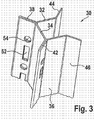
- the angular configuration of the inner part profile 30 is clearly in the Fig. 3 recognizable, which shows the inner part profile 30 in a perspective plan view.
- the seamed profile extensions 38, 42 show the system perforations of rectangles 52 and circular openings 54. Various system perforations are possible, for example a 19 "hole or a metric punching hole 47.
- the profile extensions 38, 42 are of double wall thickness like the walls 32, 34, 36 or the lugs 44, 46 are formed, so that the necessary stability for attaching components is provided
- the inner partial profile 30 can be produced as a sheet-metal bent stamped part and is then produced by means of an outer partial profile (FIG. Fig. 2 ) to a frame profile 10 according to the present invention.
- FIG Fig. 4 A corner joint in the floor area of a frame with frame profiles 10a, 10b and 10d according to the present invention is shown in FIG Fig. 4 shown.
- the inner section profile 30 of the vertical frame profile 10d is designed to be shorter than required by the cabinet dimension. This means a saving of material, also has to be subsequently not or only very little notched.
- the horizontal frame profiles 10a, 10b are cut at their profile lugs 38, 42 mitred, in which case, if necessary, still necessary adjustments of the inner section profile 30 is made to the geometry of the corner.
- the outer part profile 20 does not need to be processed further.
- Fig. 5 shows a cross-sectional view of a portion of a frame, which is composed of frame profiles 10, 10 'according to the present invention. Due to the perforated, folded profile approaches 38, 42 an assembly of structural components, such as chassis, from both sides of the profile approaches 38, 42 allows. With suitable chassis, different levels of build on the same mounting plane can be achieved, as indicated by levels 1, level 2, level 3 and level 4.
- the frame profile according to the present invention thus provides a material saving, without restricting the functionality.
Landscapes
- Engineering & Computer Science (AREA)
- Power Engineering (AREA)
- Casings For Electric Apparatus (AREA)
- Assembled Shelves (AREA)
- Patch Boards (AREA)
Description
- Die Erfindung betrifft ein Rahmenprofil für ein Rahmengestell eines Schaltschrankes. Das Rahmenprofil besteht aus einem Außenteilprofil, das aus einem ersten Material hergestellt ist, wobei das Außenteilprofil zumindest eine erste Wand des Rahmenprofils, die eine Hohlkammer teilweise begrenzt, bildet, und aus einem Innenprofil, das aus einem zweiten Material hergestellt ist, welches von dem ersten Material in mindestens einer Eigenschaft unterschiedlich ist, wobei das Innenprofil zumindest eine weitere Wand der Hohlkammer bildet. Ein derartiges Rahmenprofil ist aus der
US 2013/0221813 A1 bekannt. - Rahmenprofile sind in vielfältigen Ausgestaltungen bekannt, lediglich beispielhaft genannt seien Profile gemäß der
DE 195 36 950 C1 , derEP 0 789 983 B1 und derEP 1 601 074 B1 . Alle diese Profile haben eine mehr oder weniger komplexe Struktur, wobei von der Herstellerseite und auch der Benutzerseite her der Wunsch besteht, Material zu sparen und viele Funktionalitäten zur Verfügung zu haben. - Es ist daher die Aufgabe der Erfindung, ein Rahmenprofil für ein Rahmengestell eines Schaltschrankes zur Verfügung zu stellen, das bei gleichbleibender Steifigkeit und Tragfähigkeit für Einhängechassis eine Materialersparnis ermöglicht.
- Diese Aufgabe wird durch ein Rahmenprofil nach Anspruch 1 gelöst. Vorteilhafte Ausgestaltungen sind Gegenstand der Unteransprüche. Ein Rahmengestell für einen Schaltschrank, bei dem ein erfindungsgemäßes Rahmenprofil verbaut ist, ist Gegenstand des Anspruchs 13.
Erfindungsgemäß ist die Hohlkammer über die Länge des Rahmenprofils durchgängig ausgeführt und das Innenteilprofil zur Bildung mindestens eines Profilansatzes gefalzt, wobei der Profilansatz mit einer Lochung versehen ist. - Beispielsweise kann das Außenteilprofil aus einem Material bestehen, das korrosiv beständiger ist, als das Material des Innenteilprofils.
- Auch kann vorgesehen sein, dass die Stärke des Außenteilprofils von der Stärke des Innenteilprofis unterschiedlich ist, insbesondere größer ist als die Stärke des Innenteilprofils.
- Dadurch, dass die Hohlkammerüber die gesamte Länge des Rahmenprofils durchgängig ist, steht in der Hohlkammer ein Optionsraum zur Verfügung, der in vielfältiger Weise genutzt werden kann. So kann daran gedacht werden, Kabel durch die Hohlkammer zu ziehen, beispielsweise für Datenleitungen, die dann durch das Material des Außenteilprofils und des Innenteilprofils abgeschirmt und somit vor Störungen geschützt sind.
- Auch kann vorgesehen sein, dass die Hohlkammer mit einem Hartschaum versteift ist. Genauso sind Befüllungen mit Weichschaum denkbar, damit die Hohlkammer dämpfende Eigenschaften entwickelt. Auch können offenporige Strukturen, insbesondere offenporige Weichschäume vorgesehen sein, die einen Medientransport zulassen.
- Der Hartschaum oder der Weichschaum kann dabei ein Schaum auf Polyester- oder Polyurethanbasis sein. Auch Metallschäume sind denkbar, ebenso wie Beton und andere anorganische und organische Materialien.
- Bei gleichen Funktions- und Außenmaßen ist so eine Vielzahl von Profilen mit unterschiedlichsten Eigenschaften möglich, ohne dass die Funktionsgeometrie verändert wird. So kann der Hohlraum so gestaltet werden, dass sich die Eigenschaften des Profils einstellen lassen.
- Nach einer bevorzugten Ausgestaltung der Erfindung können das Außenteilprofil und das Innenteilprofil zu zumindest einem Profilansatz zusammengeführt sein, der sich von der Hohlkammer weg erstreckt. Es entsteht damit ein geradliniger Steg mit eckiger Außenkontur, auf den eine Aufsteckdichtung aufgesetzt werden kann. Dieses kann eine übliche Lippendichtung sein, aber auch eine Dichtung, wie sie Gegenstand der gleichzeitig eingereichten
DE 10 2014 101 401 A1 ist. - Dadurch, dass das Innenteilprofil zur Bildung mindestens eines Profilansatzes gefalzt ist, kann bei nur halber Materialdicke somit eine bestimmte Befestigungsdicke beibehalten werden, oder diese kann trotz Materialeinspannung vergrößert werden. Damit wird genügend Materialdicke für z.B. Blechschrauben zur Verfügung gestellt, für die eine Mindestdicke erforderlich ist.
- Die Hohlkammer ist vorzugsweise im Querschnitt rechteckig oder quadratisch, kann aber auch zum Beispiel trapezförmig oder als Parallelogramm, also rautenähnlich, ausgebildet sein. Weiter vorzugsweise ist der Profilansatz oder sind die Profilansätze an Kanten der Hohlkammer ausgebildet. Dabei ist vorgesehen, dass die Profilansätze mit den angrenzenden Profilseiten einen Winkel von 135° einschließen. Bei vier Profilansätzen an den vier Kanten der Hohlkammer ergibt sich somit ein symmetrisches Rahmenprofil, dessen Profilansätze unterschiedlichen Erfordernissen genügen.
- Es ist bevorzugt, dass die Lochung eine Systemlochung ist. Bei zwei derartigen Profilansätzen ergeben sich mehrere Aufbauebenen, so dass mit einem geeigneten Chassis mit gleichen Teilen auf der gleichen Befestigungsebene gearbeitet werden kann. Die Montage von Komponenten ist dabei von beiden Seiten des betreffenden Profilansatzes möglich.
- Aus Rahmenprofilen gemäß der vorliegenden Erfindung kann ein Rahmengestell für einen Schaltschrank aufgebaut werden, bei dem ein solches Rahmenprofil zumindest als Vertikalprofil verbaut ist, um die verbesserten Montagemöglichkeiten ausnutzen zu können. Es ist aber ebenso vorteilhaft, das Rahmenprofil gemäß der vorliegenden Erfindung auch als Horizontalprofil einzusetzen, und zwar sowohl im Decken- als auch im Bodenbereich. Gerade im Bodenbereich kann dann die Eckenlösung materialsparender ausgeführt werden, wenn das Innenteilprofil kürzer als von der Schrankabmessung benötigt ausgeführt wird, so dass es nachträglich nicht oder nur sehr wenig ausgeklinkt werden muss.
- Die Erfindung wird im Folgenden anhand der beigefügten Zeichnung näher erläutert. Dabei sind die Darstellungen nicht notwendigerweise maßstabsgetreu. Es zeigt:
- Fig. 1
- eine Querschnittsansicht eines Rahmenprofils gemäß der vorliegenden Erfindung;
- Fig. 2
- eine Frontansicht des Rahmenprofils aus
Fig. 1 ; - Fig. 3
- eine perspektivische Ansicht eines Innenteilprofils;
- Fig. 4
- eine Eckverbindung von drei Rahmenprofilen gemäß der vorliegenden Erfindung im Deckenbereich eines Rahmengestells für einen Schaltschrank;
- Fig. 5
- eine Eckverbindung im Bodenbereich eines Rahmengestells für einen Schaltschrank; und
- Fig. 6
- eine Schnittdarstellung durch einen Teil eines Rahmengestells mit zwei Rahmenprofilen gemäß der vorliegenden Erfindung, anhand der die unterschiedlichen Montageebene verdeutlicht werden.
-
Fig. 1 zeigt eine Querschnittsdarstellung eines Rahmenprofils 10 für ein Rahmengestell eines Schaltschranks, das ein Außenteilprofil 20 aufweist, welches aus einem ersten Material hergestellt ist. Das Außenteilprofil bildet zumindest eine erste Wand 22 des Rahmenprofils 10, die eine Hohlkammer 40 teilweise begrenzt. Von der ersten Wand gehen unter einem Winkel von etwa 135° zwei Ansätze 24, 26 ab. Das Rahmenprofil 10 umfasst weiterhin ein Innenteilprofil 30, das aus einem zweiten Material hergestellt ist, welches von dem ersten Material in mindestens einer Eigenschaft unterschiedlich ist. Dies kann eine physikalische oder eine chemische Eigenschaft sein, beispielsweise kann das Außenteilprofil 20 aus einem Material hergestellt sein, das korrosionsstabiler ist als das Material des Innenteilprofils 30. Auch weist das Außenteilprofil 20 eine Wandstärke auf, die größer ist als die Wandstärke des Innenteilprofils 30. Das Innenteilprofil 30 bildet zumindest eine weitere Wand der Hohlkammer, im dargestellten Ausführungsbeispiel werden drei weitere Wände 32, 34, 36 der Hohlkammer 40 durch das Innenteilprofil 30 gebildet. Insgesamt wird so eine Hohlkammer 40 gebildet, die im Querschnitt rechteckig oder quadratisch ist. An den Kanten der Hohlkammer 40 sind Profilansätze ausgebildet, die sich von der Hohlkammer 40 weg erstrecken. Zwei verschiedene Arten von Profilansätzen sind bevorzugt, nämlich einerseits Profilansätze, die aus Ansätzen 24, 26 des Außenteilprofils 20 und damit verbundenen Ansätzen 44, 46 des Innenteilprofils 30 gebildet sind. Ein derartiger Profilansatz, beispielsweise 26, 46, ist geradlinig und hat eine eckige Außenkontur, so dass eine Aufsteckdichtung 50 einfach aufzuschieben ist. Weitere Profilansätze 38, 42 sind dadurch gebildet, dass das Material des Innenteilprofils 30 gefalzt wird, so dass die Profilansätze 38, 42 sozusagen doppellagig aus dem Material des Innenteilprofils 30 ausgeführt sind. Diese gefalzten Profilansätze 38, 42 weisen Lochungen auf, die besser in denFig. 2 und3 zu erkennen sind. - Der Hohlraum 40 kann zur Kabelführung genutzt werden. Auch Befüllungen mit Hartschaum oder Weichschaum, beispielsweise auf Polyester- oder Polyurethanbasis, ist möglich, um das Rahmenprofil 10 zu versteifen oder ihm Dämpfungseigenschaften zu verleihen.
Fig. 2 zeigt eine Draufsicht auf das Profil derFig. 1 . Am Profilansatz 38 ist die Lochung zu erkennen, die aus abwechselnd rechteckigen und kreisrunden Lochungen 52, 54 besteht. Eine ähnliche Lochung, die auch als Systemlochung bezeichnet wird, ist im Profilansatz 42 vorgesehen, dort aber in der Darstellung nicht erkennbar. Die Profilansätze 38, 42 gehen über die Wand 34 ineinander über, wobei sie sich unter einem Winkel von etwa 135° von dieser erstrecken (sieheFig. 1 ). Der Profilansatz 42 geht über eine Wand 36 in den Ansatz 46 über, wobei auch hier die Übergangswinkel in der Größenordnung von 135° liegen. - Die winklige Ausgestaltung des Innenteilprofils 30 ist deutlich in der
Fig. 3 zu erkennen, die das Innenteilprofil 30 in einer perspektivischen Draufsicht zeigt. Die gefalzten Profilansätze 38, 42 zeigen die Systemlochung aus Rechtecken 52 und kreisrunden Öffnungen 54. Verschiedene Systemlochungen sind möglich, beispielsweise eine 19"-Lochungen oder eine metrische Lochung. Durch das Falzen sind die Profilansätze 38, 42 mit doppelter Wandstärke wie die Wände 32, 34, 36 bzw. die Ansätze 44, 46 ausgebildet, so dass die notwendige Stabilität zum Anbringen von Komponenten gegeben ist. Das Innenteilprofil 30 kann als Blech-Biegestanzteil hergestellt werden und wird dann mittels eines Außenteilprofils (Fig. 2 ) zu einem Rahmenprofil 10 gemäß der vorliegenden Erfindung ergänzt. - Eine Eckverbindung im Bodenbereich eines Rahmengestells mit Rahmenprofilen 10a, 10b und 10d gemäß der vorliegenden Erfindung ist in
Fig. 4 gezeigt. Das Innenteilprofil 30 des vertikalen Rahmenprofils 10d ist dabei kürzer ausgeführt, als es von der Schrankabmessung benötigt wird. Dies bedeutet eine Materialersparnis, außerdem muss nachträglich nicht oder nur sehr wenig ausgeklinkt werden. Die horizontalen Rahmenprofile 10a, 10b sind an ihren Profilansätzen 38, 42 auf Gehrung geschnitten, wobei dann gegebenenfalls noch notwendige Anpassungen des Innenteilprofils 30 an die Geometrie der Ecke erfolgt. Das Außenteilprofil 20 muss nicht weiter bearbeitet werden. -
Fig. 5 zeigt eine Querschnittsansicht eines Teils eines Rahmengestells, das aus Rahmenprofilen 10, 10' gemäß der vorliegenden Erfindung aufgebaut ist. Durch die gelochten, gefalzten Profilansätze 38, 42 ist eine Montage von Aufbaukomponenten, z.B. von Chassis, von beiden Seiten der Profilansätze 38, 42 ermöglicht. Mit geeigneten Chassis können so mit gleichen Teilen auf der gleichen Befestigungsebene verschiedene Aufbauebenen realisiert werden, wie es durch Ebene 1, Ebene 2, Ebene 3 und Ebene 4 angezeigt ist. - Das Rahmenprofil gemäß der vorliegenden Erfindung bietet somit eine Materialersparnis, ohne die Funktionalität einzuschränken.
- Die in der vorstehenden Beschreibung, in den Zeichnungen sowie in den Ansprüchen offenbarten Merkmale der Erfindung können sowohl einzeln als auch in beliebiger Kombination für die Verwirklichung der Erfindung wesentlich sein, wie in den beigefügten Ansprüchen definiert.
Claims (13)
- Rahmenprofil für ein Rahmengestell eines Schaltschrankes, bestehend aus- einem Außenteilprofil (20), das aus einem ersten Material hergestellt ist, wobei das Außenteilprofil (20) zumindest eine erste Wand (22) des Rahmenprofils (10), die eine Hohlkammer (40) teilweise begrenzt, bildet; und- einem Innenteilprofil (30), das aus einem zweiten Material hergestellt ist, welches von dem ersten Material in mindestens einer Eigenschaft unterschiedlich ist, wobei das Innenteilprofil (30) zumindest eine weitere Wand (32, 34, 36) der Hohlkammer (40) bildet,dadurch gekennzeichnet, dass die Hohlkammer (40) über die Länge des Rahmenprofils (10) durchgängig ausgeführt und das Innenteilprofil (30) zur Bildung mindestens eines Profilansatzes (38, 42) gefalzt ist, der mit einer Lochung (52, 54) versehen ist.
- Rahmenprofil nach Anspruch 1, dadurch gekennzeichnet, dass die Stärke des Außenteilprofils (20) von der Stärke des Innenteilprofils (30) unterschiedlich ist.
- Rahmenprofil nach Anspruch 1, dadurch gekennzeichnet, dass die Hohlkammer (40) mit einem Hartschaum versteift ist.
- Rahmenprofil nach Anspruch 1, dadurch gekennzeichnet, dass die Hohlkammer (40) mit einem Weichschaum befüllt ist.
- Rahmenprofil nach Anspruch 4, dadurch gekennzeichnet, dass die Hohlkammer (40) mit einem offenporigen Weichschaum befüllt ist.
- Rahmenprofil nach einem der Ansprüche 1 bis 4, dadurch gekennzeichnet, dass der Hartschaum oder Weichschaum ein Schaum auf Polyester- oder Polyurethanbasis ist.
- Rahmenprofil nach Anspruch 1, dadurch gekennzeichnet, dass die Hohlkammer (40) mit einem anorganischen Material, wie Metallschaum oder Beton, befüllt ist.
- Rahmenprofil nach Anspruch 1, dadurch gekennzeichnet, dass das Außenteilprofil (20) und das Innenteilprofil (30) zu zumindest einem Profilansatz (24, 44; 26, 46) zusammengeführt sind, der sich von der Hohlkammer (40) weg erstreckt.
- Rahmenprofil nach Anspruch 1, dadurch gekennzeichnet, dass die Hohlkammer (40) im Querschnitt rechteckig, quadratisch, trapezförmig oder rautenähnlich ist.
- Rahmenprofil nach Anspruch 8, dadurch gekennzeichnet, das der Profilansatz oder die Profilansätze (24, 44; 26, 46; 38; 42) an Kanten der Hohlkammer (40) ausgebildet sind.
- Rahmenprofil nach Anspruch 1, dadurch gekennzeichnet, dass die Profilansätze (24, 44; 26, 46; 38; 42) mit den angrenzenden Profilseiten (22, 32, 34, 36) einen Winkel von 135° einschließen.
- Rahmenprofil nach Anspruch 1, dadurch gekennzeichnet, dass die Lochung (52, 54) eine Systemlochung ist.
- Rahmengestell für einen Schaltschrank, bei dem ein Rahmenprofil nach einem der Ansprüche 1 bis 12 zumindest als Vertikalprofil verbaut ist.
Priority Applications (1)
| Application Number | Priority Date | Filing Date | Title |
|---|---|---|---|
| PL15714161T PL3103169T3 (pl) | 2014-02-05 | 2015-01-28 | Profil ramowy do wykonania korpusu ramowego szafy rozdzielczej |
Applications Claiming Priority (2)
| Application Number | Priority Date | Filing Date | Title |
|---|---|---|---|
| DE102014101402.2A DE102014101402B4 (de) | 2014-02-05 | 2014-02-05 | Rahmenprofil für ein Rahmengestell eines Schaltschrankes |
| PCT/DE2015/100033 WO2015117596A1 (de) | 2014-02-05 | 2015-01-28 | Rahmenprofil für ein rahmengestell eines schaltschrankes |
Publications (2)
| Publication Number | Publication Date |
|---|---|
| EP3103169A1 EP3103169A1 (de) | 2016-12-14 |
| EP3103169B1 true EP3103169B1 (de) | 2019-10-23 |
Family
ID=52810913
Family Applications (1)
| Application Number | Title | Priority Date | Filing Date |
|---|---|---|---|
| EP15714161.5A Active EP3103169B1 (de) | 2014-02-05 | 2015-01-28 | Rahmenprofil für ein rahmengestell eines schaltschrankes |
Country Status (6)
| Country | Link |
|---|---|
| US (1) | US9966738B2 (de) |
| EP (1) | EP3103169B1 (de) |
| CN (1) | CN106063061B (de) |
| DE (1) | DE102014101402B4 (de) |
| PL (1) | PL3103169T3 (de) |
| WO (1) | WO2015117596A1 (de) |
Families Citing this family (3)
| Publication number | Priority date | Publication date | Assignee | Title |
|---|---|---|---|---|
| DE102014101404B4 (de) | 2014-02-05 | 2017-11-16 | Rittal Gmbh & Co. Kg | Rahmengestell für einen Schalt- oder Verteilerschrank |
| DE102015121192B4 (de) | 2015-12-04 | 2019-09-19 | Rittal Gmbh & Co. Kg | Rahmengestell für einen Schaltschrank |
| DE102016124078B3 (de) * | 2016-12-12 | 2018-05-09 | Rittal Gmbh & Co. Kg | Verbindungsanordnung für die Verbindung von zwei Schaltschrankrahmengestellen |
Family Cites Families (27)
| Publication number | Priority date | Publication date | Assignee | Title |
|---|---|---|---|---|
| DE1223663B (de) * | 1955-08-09 | 1966-08-25 | Ernst Wieger | Aus Walz- und Profileisen zusammengeschweisster Maschinenteil, insbesondere Staender fuer Tafelscheren, Abkantpressen od. dgl. |
| US3891288A (en) * | 1973-12-27 | 1975-06-24 | John L Marquette | Plug-in equipment shipping container and rack system |
| US4158998A (en) * | 1976-05-12 | 1979-06-26 | The Mead Corporation | Shelf support structure |
| US4351244A (en) * | 1980-01-29 | 1982-09-28 | The Mead Corporation | Shelving system |
| GB2121676B (en) | 1982-06-08 | 1986-01-15 | Peter Baron | Frame construction |
| FR2568326A1 (fr) * | 1984-07-27 | 1986-01-31 | Dauphine Cadres | Systeme pour l'assemblage des elements constitutifs des meubles demontables et ensembles analogues |
| DE3731547C3 (de) * | 1987-09-19 | 1995-05-04 | Loh Kg Rittal Werk | Schaltschrank |
| DE9217801U1 (de) * | 1992-12-23 | 1993-02-25 | Hansa Ventilatoren u. Maschinenbau Neumann GmbH & Co KG, 2915 Saterland | Profil zur Aufnahme von Beplankungselementen |
| DE4336187C2 (de) | 1993-10-23 | 1996-12-12 | Loh Kg Rittal Werk | Rahmenschenkel für ein Rahmengestell eines Schaltschrankes |
| DE4439551C1 (de) | 1994-11-05 | 1995-12-21 | Loh Kg Rittal Werk | Rahmenschenkel für ein Rahmengestell eines Schaltschrankes |
| DE19536950C1 (de) | 1995-10-04 | 1996-11-21 | Loh Kg Rittal Werk | Rahmenschenkel für ein Rahmengestell eines Schaltschrankes |
| DE19837367C2 (de) * | 1998-08-18 | 2003-01-09 | Rittal Gmbh & Co Kg | Rahmenprofil für einen Schaltschrank |
| CN2402099Y (zh) * | 1999-12-09 | 2000-10-18 | 上海贝尔有限公司 | 一种机柜框架 |
| DE10101649C1 (de) | 2001-01-16 | 2002-08-29 | Daimler Chrysler Ag | Mit Metallschaum verstärktes Strukturelement |
| US6831225B2 (en) * | 2001-05-15 | 2004-12-14 | Prima Corporation | Method and arrangement for providing electrical power to an electronic equipment cabinet |
| US6938389B2 (en) * | 2001-10-03 | 2005-09-06 | Steel Stitch Corporation | Roll formed staple-in awning frame and method |
| BR0202231A (pt) * | 2002-06-06 | 2004-04-27 | Melquisedec Francisquini | Aperfeiçoamento em perfil metálico para composição de estruturas para montagem de quadros elétricos |
| BR0301083A (pt) | 2003-04-03 | 2004-11-03 | Melquisedec Francisquini | Aperfeiçoamento em perfil metálico para composição de estruturas para montagem de quadros elétricos |
| FR2870995B1 (fr) | 2004-05-28 | 2006-09-01 | Hispano Mecano Electrica Sa Sa | Armoire electrique a profiles d'ossature |
| FI120915B (fi) * | 2004-08-27 | 2010-04-30 | Runtech Systems Oy | Palkkirakenne |
| US20070069613A1 (en) * | 2005-09-29 | 2007-03-29 | Alexander Dinota | Outdoor base station housing assembly |
| CN101577398B (zh) * | 2009-06-10 | 2012-05-02 | 深圳市怡富精密机械有限公司 | 一种便于装配的机柜框架及其装配方法 |
| DE102010033319A1 (de) * | 2010-08-04 | 2012-02-09 | Protektorwerk Florenz Maisch Gmbh & Co. Kg | Schrankprofil, insbesondere Schaltschrankprofil und Schrank, insbesondere Schaltschrank |
| US8901438B2 (en) * | 2010-09-10 | 2014-12-02 | Chatsworth Products, Inc. | Electronic equipment cabinet structure |
| CN202797616U (zh) * | 2012-09-20 | 2013-03-13 | 天津市滨海新区奕晟电气设备有限公司 | 电控柜用加固纵梁型钢 |
| DE102014101401A1 (de) | 2014-02-05 | 2015-08-06 | Rittal Gmbh & Co. Kg | Anreih-Schaltschranksystem |
| DE102014101404B4 (de) | 2014-02-05 | 2017-11-16 | Rittal Gmbh & Co. Kg | Rahmengestell für einen Schalt- oder Verteilerschrank |
-
2014
- 2014-02-05 DE DE102014101402.2A patent/DE102014101402B4/de active Active
-
2015
- 2015-01-28 US US15/116,770 patent/US9966738B2/en active Active
- 2015-01-28 WO PCT/DE2015/100033 patent/WO2015117596A1/de not_active Ceased
- 2015-01-28 EP EP15714161.5A patent/EP3103169B1/de active Active
- 2015-01-28 CN CN201580007452.5A patent/CN106063061B/zh active Active
- 2015-01-28 PL PL15714161T patent/PL3103169T3/pl unknown
Non-Patent Citations (1)
| Title |
|---|
| None * |
Also Published As
| Publication number | Publication date |
|---|---|
| EP3103169A1 (de) | 2016-12-14 |
| PL3103169T3 (pl) | 2020-03-31 |
| US9966738B2 (en) | 2018-05-08 |
| WO2015117596A1 (de) | 2015-08-13 |
| CN106063061B (zh) | 2019-03-22 |
| DE102014101402A1 (de) | 2015-08-20 |
| DE102014101402B4 (de) | 2024-10-17 |
| CN106063061A (zh) | 2016-10-26 |
| US20160352079A1 (en) | 2016-12-01 |
Similar Documents
| Publication | Publication Date | Title |
|---|---|---|
| EP3384568B1 (de) | Rahmenprofil für ein rahmengestell eines schaltschranks und ein entsprechendes rahmengestell | |
| DE102014101404B4 (de) | Rahmengestell für einen Schalt- oder Verteilerschrank | |
| EP0404284A1 (de) | Gerüst für einen Schaltschrank aus mehrfach abgewinkelten Profilelementen | |
| DE3815140C2 (de) | Blendrahmen zur Bildung einer Fugenschalung zwecks Verbindung von einzelnen Glasbauelementen | |
| DE102014101402B4 (de) | Rahmenprofil für ein Rahmengestell eines Schaltschrankes | |
| EP0312646A2 (de) | Mittelträger für Fensterrahmen | |
| DE19739644C2 (de) | Wand für die Kabine einer Lackieranlage | |
| DE102013014530A1 (de) | Rollladenkastenbaugruppe, sowie Kastenwandprofil und Zusatzprofil dafür | |
| DE10227217B4 (de) | Unterflur-Bodendose | |
| DE2543174A1 (de) | Fassadenunterkonstruktion | |
| DE9302320U1 (de) | Wandelement, insbesondere Doppelwandelement | |
| DE202014104306U1 (de) | Möbelplatte aus Holz oder einem Holzwerkstoff | |
| DE19948467A1 (de) | Kasten für Rolläden oder dergleichen | |
| DE3430497C2 (de) | Möbel | |
| DE202008007983U1 (de) | Bodenrevisionsvorrichtung | |
| DE202006004211U1 (de) | Schrank | |
| DE102009003910A1 (de) | Tragschiene für eine Vorrichtung zur Halterung von Wandplatten an einer Wand sowie Fassadenbekleidung | |
| DE19836171B4 (de) | Fertigteilsatz zur Errichtung eines Gebäudes | |
| DE202017002614U1 (de) | Bürsteneinführung für Schaltschrankböden | |
| EP3103114B1 (de) | Schallabsorber | |
| DE202023104429U1 (de) | Brandabschottung für Leitungen in Gebäuden | |
| DD262886A5 (de) | Mitteltraeger fuer fensterrahmen | |
| DE102015121325A1 (de) | Türflügel und flächenbündige Türeinheit | |
| DE202008011511U1 (de) | Sockelleistenanordnung | |
| AT505808A1 (de) | Justierschiene fur die anpassung von zwischenwanden an angrenzende baukírper |
Legal Events
| Date | Code | Title | Description |
|---|---|---|---|
| PUAI | Public reference made under article 153(3) epc to a published international application that has entered the european phase |
Free format text: ORIGINAL CODE: 0009012 |
|
| STAA | Information on the status of an ep patent application or granted ep patent |
Free format text: STATUS: REQUEST FOR EXAMINATION WAS MADE |
|
| 17P | Request for examination filed |
Effective date: 20160712 |
|
| AK | Designated contracting states |
Kind code of ref document: A1 Designated state(s): AL AT BE BG CH CY CZ DE DK EE ES FI FR GB GR HR HU IE IS IT LI LT LU LV MC MK MT NL NO PL PT RO RS SE SI SK SM TR |
|
| AX | Request for extension of the european patent |
Extension state: BA ME |
|
| DAX | Request for extension of the european patent (deleted) | ||
| GRAP | Despatch of communication of intention to grant a patent |
Free format text: ORIGINAL CODE: EPIDOSNIGR1 |
|
| STAA | Information on the status of an ep patent application or granted ep patent |
Free format text: STATUS: GRANT OF PATENT IS INTENDED |
|
| INTG | Intention to grant announced |
Effective date: 20190715 |
|
| GRAS | Grant fee paid |
Free format text: ORIGINAL CODE: EPIDOSNIGR3 |
|
| GRAA | (expected) grant |
Free format text: ORIGINAL CODE: 0009210 |
|
| STAA | Information on the status of an ep patent application or granted ep patent |
Free format text: STATUS: THE PATENT HAS BEEN GRANTED |
|
| AK | Designated contracting states |
Kind code of ref document: B1 Designated state(s): AL AT BE BG CH CY CZ DE DK EE ES FI FR GB GR HR HU IE IS IT LI LT LU LV MC MK MT NL NO PL PT RO RS SE SI SK SM TR |
|
| REG | Reference to a national code |
Ref country code: GB Ref legal event code: FG4D Free format text: NOT ENGLISH |
|
| REG | Reference to a national code |
Ref country code: CH Ref legal event code: EP |
|
| REG | Reference to a national code |
Ref country code: IE Ref legal event code: FG4D Free format text: LANGUAGE OF EP DOCUMENT: GERMAN |
|
| REG | Reference to a national code |
Ref country code: DE Ref legal event code: R096 Ref document number: 502015010733 Country of ref document: DE |
|
| REG | Reference to a national code |
Ref country code: AT Ref legal event code: REF Ref document number: 1194734 Country of ref document: AT Kind code of ref document: T Effective date: 20191115 |
|
| REG | Reference to a national code |
Ref country code: NL Ref legal event code: MP Effective date: 20191023 |
|
| REG | Reference to a national code |
Ref country code: LT Ref legal event code: MG4D |
|
| PG25 | Lapsed in a contracting state [announced via postgrant information from national office to epo] |
Ref country code: LT Free format text: LAPSE BECAUSE OF FAILURE TO SUBMIT A TRANSLATION OF THE DESCRIPTION OR TO PAY THE FEE WITHIN THE PRESCRIBED TIME-LIMIT Effective date: 20191023 Ref country code: NL Free format text: LAPSE BECAUSE OF FAILURE TO SUBMIT A TRANSLATION OF THE DESCRIPTION OR TO PAY THE FEE WITHIN THE PRESCRIBED TIME-LIMIT Effective date: 20191023 Ref country code: BG Free format text: LAPSE BECAUSE OF FAILURE TO SUBMIT A TRANSLATION OF THE DESCRIPTION OR TO PAY THE FEE WITHIN THE PRESCRIBED TIME-LIMIT Effective date: 20200123 Ref country code: SE Free format text: LAPSE BECAUSE OF FAILURE TO SUBMIT A TRANSLATION OF THE DESCRIPTION OR TO PAY THE FEE WITHIN THE PRESCRIBED TIME-LIMIT Effective date: 20191023 Ref country code: PT Free format text: LAPSE BECAUSE OF FAILURE TO SUBMIT A TRANSLATION OF THE DESCRIPTION OR TO PAY THE FEE WITHIN THE PRESCRIBED TIME-LIMIT Effective date: 20200224 Ref country code: FI Free format text: LAPSE BECAUSE OF FAILURE TO SUBMIT A TRANSLATION OF THE DESCRIPTION OR TO PAY THE FEE WITHIN THE PRESCRIBED TIME-LIMIT Effective date: 20191023 Ref country code: LV Free format text: LAPSE BECAUSE OF FAILURE TO SUBMIT A TRANSLATION OF THE DESCRIPTION OR TO PAY THE FEE WITHIN THE PRESCRIBED TIME-LIMIT Effective date: 20191023 Ref country code: NO Free format text: LAPSE BECAUSE OF FAILURE TO SUBMIT A TRANSLATION OF THE DESCRIPTION OR TO PAY THE FEE WITHIN THE PRESCRIBED TIME-LIMIT Effective date: 20200123 Ref country code: GR Free format text: LAPSE BECAUSE OF FAILURE TO SUBMIT A TRANSLATION OF THE DESCRIPTION OR TO PAY THE FEE WITHIN THE PRESCRIBED TIME-LIMIT Effective date: 20200124 |
|
| PG25 | Lapsed in a contracting state [announced via postgrant information from national office to epo] |
Ref country code: IS Free format text: LAPSE BECAUSE OF FAILURE TO SUBMIT A TRANSLATION OF THE DESCRIPTION OR TO PAY THE FEE WITHIN THE PRESCRIBED TIME-LIMIT Effective date: 20200224 Ref country code: RS Free format text: LAPSE BECAUSE OF FAILURE TO SUBMIT A TRANSLATION OF THE DESCRIPTION OR TO PAY THE FEE WITHIN THE PRESCRIBED TIME-LIMIT Effective date: 20191023 Ref country code: HR Free format text: LAPSE BECAUSE OF FAILURE TO SUBMIT A TRANSLATION OF THE DESCRIPTION OR TO PAY THE FEE WITHIN THE PRESCRIBED TIME-LIMIT Effective date: 20191023 |
|
| PG25 | Lapsed in a contracting state [announced via postgrant information from national office to epo] |
Ref country code: AL Free format text: LAPSE BECAUSE OF FAILURE TO SUBMIT A TRANSLATION OF THE DESCRIPTION OR TO PAY THE FEE WITHIN THE PRESCRIBED TIME-LIMIT Effective date: 20191023 |
|
| REG | Reference to a national code |
Ref country code: DE Ref legal event code: R097 Ref document number: 502015010733 Country of ref document: DE |
|
| PG2D | Information on lapse in contracting state deleted |
Ref country code: IS |
|
| PG25 | Lapsed in a contracting state [announced via postgrant information from national office to epo] |
Ref country code: RO Free format text: LAPSE BECAUSE OF FAILURE TO SUBMIT A TRANSLATION OF THE DESCRIPTION OR TO PAY THE FEE WITHIN THE PRESCRIBED TIME-LIMIT Effective date: 20191023 Ref country code: CZ Free format text: LAPSE BECAUSE OF FAILURE TO SUBMIT A TRANSLATION OF THE DESCRIPTION OR TO PAY THE FEE WITHIN THE PRESCRIBED TIME-LIMIT Effective date: 20191023 Ref country code: ES Free format text: LAPSE BECAUSE OF FAILURE TO SUBMIT A TRANSLATION OF THE DESCRIPTION OR TO PAY THE FEE WITHIN THE PRESCRIBED TIME-LIMIT Effective date: 20191023 Ref country code: EE Free format text: LAPSE BECAUSE OF FAILURE TO SUBMIT A TRANSLATION OF THE DESCRIPTION OR TO PAY THE FEE WITHIN THE PRESCRIBED TIME-LIMIT Effective date: 20191023 Ref country code: DK Free format text: LAPSE BECAUSE OF FAILURE TO SUBMIT A TRANSLATION OF THE DESCRIPTION OR TO PAY THE FEE WITHIN THE PRESCRIBED TIME-LIMIT Effective date: 20191023 Ref country code: IS Free format text: LAPSE BECAUSE OF FAILURE TO SUBMIT A TRANSLATION OF THE DESCRIPTION OR TO PAY THE FEE WITHIN THE PRESCRIBED TIME-LIMIT Effective date: 20200223 |
|
| PLBE | No opposition filed within time limit |
Free format text: ORIGINAL CODE: 0009261 |
|
| STAA | Information on the status of an ep patent application or granted ep patent |
Free format text: STATUS: NO OPPOSITION FILED WITHIN TIME LIMIT |
|
| PG25 | Lapsed in a contracting state [announced via postgrant information from national office to epo] |
Ref country code: MC Free format text: LAPSE BECAUSE OF FAILURE TO SUBMIT A TRANSLATION OF THE DESCRIPTION OR TO PAY THE FEE WITHIN THE PRESCRIBED TIME-LIMIT Effective date: 20191023 Ref country code: SM Free format text: LAPSE BECAUSE OF FAILURE TO SUBMIT A TRANSLATION OF THE DESCRIPTION OR TO PAY THE FEE WITHIN THE PRESCRIBED TIME-LIMIT Effective date: 20191023 Ref country code: SK Free format text: LAPSE BECAUSE OF FAILURE TO SUBMIT A TRANSLATION OF THE DESCRIPTION OR TO PAY THE FEE WITHIN THE PRESCRIBED TIME-LIMIT Effective date: 20191023 |
|
| REG | Reference to a national code |
Ref country code: CH Ref legal event code: PL |
|
| GBPC | Gb: european patent ceased through non-payment of renewal fee |
Effective date: 20200128 |
|
| 26N | No opposition filed |
Effective date: 20200724 |
|
| REG | Reference to a national code |
Ref country code: BE Ref legal event code: MM Effective date: 20200131 |
|
| PG25 | Lapsed in a contracting state [announced via postgrant information from national office to epo] |
Ref country code: LU Free format text: LAPSE BECAUSE OF NON-PAYMENT OF DUE FEES Effective date: 20200128 Ref country code: GB Free format text: LAPSE BECAUSE OF NON-PAYMENT OF DUE FEES Effective date: 20200128 |
|
| PG25 | Lapsed in a contracting state [announced via postgrant information from national office to epo] |
Ref country code: BE Free format text: LAPSE BECAUSE OF NON-PAYMENT OF DUE FEES Effective date: 20200131 Ref country code: SI Free format text: LAPSE BECAUSE OF FAILURE TO SUBMIT A TRANSLATION OF THE DESCRIPTION OR TO PAY THE FEE WITHIN THE PRESCRIBED TIME-LIMIT Effective date: 20191023 Ref country code: LI Free format text: LAPSE BECAUSE OF NON-PAYMENT OF DUE FEES Effective date: 20200131 Ref country code: CH Free format text: LAPSE BECAUSE OF NON-PAYMENT OF DUE FEES Effective date: 20200131 |
|
| PG25 | Lapsed in a contracting state [announced via postgrant information from national office to epo] |
Ref country code: IE Free format text: LAPSE BECAUSE OF NON-PAYMENT OF DUE FEES Effective date: 20200128 |
|
| REG | Reference to a national code |
Ref country code: AT Ref legal event code: MM01 Ref document number: 1194734 Country of ref document: AT Kind code of ref document: T Effective date: 20200128 |
|
| PG25 | Lapsed in a contracting state [announced via postgrant information from national office to epo] |
Ref country code: AT Free format text: LAPSE BECAUSE OF NON-PAYMENT OF DUE FEES Effective date: 20200128 |
|
| PG25 | Lapsed in a contracting state [announced via postgrant information from national office to epo] |
Ref country code: MT Free format text: LAPSE BECAUSE OF FAILURE TO SUBMIT A TRANSLATION OF THE DESCRIPTION OR TO PAY THE FEE WITHIN THE PRESCRIBED TIME-LIMIT Effective date: 20191023 Ref country code: CY Free format text: LAPSE BECAUSE OF FAILURE TO SUBMIT A TRANSLATION OF THE DESCRIPTION OR TO PAY THE FEE WITHIN THE PRESCRIBED TIME-LIMIT Effective date: 20191023 |
|
| PG25 | Lapsed in a contracting state [announced via postgrant information from national office to epo] |
Ref country code: MK Free format text: LAPSE BECAUSE OF FAILURE TO SUBMIT A TRANSLATION OF THE DESCRIPTION OR TO PAY THE FEE WITHIN THE PRESCRIBED TIME-LIMIT Effective date: 20191023 |
|
| P01 | Opt-out of the competence of the unified patent court (upc) registered |
Effective date: 20230525 |
|
| PGFP | Annual fee paid to national office [announced via postgrant information from national office to epo] |
Ref country code: DE Payment date: 20260120 Year of fee payment: 12 |
|
| PGFP | Annual fee paid to national office [announced via postgrant information from national office to epo] |
Ref country code: IT Payment date: 20260130 Year of fee payment: 12 |
|
| PGFP | Annual fee paid to national office [announced via postgrant information from national office to epo] |
Ref country code: FR Payment date: 20260128 Year of fee payment: 12 |
|
| PGFP | Annual fee paid to national office [announced via postgrant information from national office to epo] |
Ref country code: TR Payment date: 20260126 Year of fee payment: 12 |
|
| PGFP | Annual fee paid to national office [announced via postgrant information from national office to epo] |
Ref country code: PL Payment date: 20260120 Year of fee payment: 12 |