EP3102853B1 - Series parallel hydraulic hybrid architecture - Google Patents
Series parallel hydraulic hybrid architecture Download PDFInfo
- Publication number
- EP3102853B1 EP3102853B1 EP15703768.0A EP15703768A EP3102853B1 EP 3102853 B1 EP3102853 B1 EP 3102853B1 EP 15703768 A EP15703768 A EP 15703768A EP 3102853 B1 EP3102853 B1 EP 3102853B1
- Authority
- EP
- European Patent Office
- Prior art keywords
- hydraulic
- displacement unit
- valve
- pump
- fluid port
- Prior art date
- Legal status (The legal status is an assumption and is not a legal conclusion. Google has not performed a legal analysis and makes no representation as to the accuracy of the status listed.)
- Active
Links
Images

Classifications
-
- F—MECHANICAL ENGINEERING; LIGHTING; HEATING; WEAPONS; BLASTING
- F16—ENGINEERING ELEMENTS AND UNITS; GENERAL MEASURES FOR PRODUCING AND MAINTAINING EFFECTIVE FUNCTIONING OF MACHINES OR INSTALLATIONS; THERMAL INSULATION IN GENERAL
- F16H—GEARING
- F16H61/00—Control functions within control units of change-speed- or reversing-gearings for conveying rotary motion ; Control of exclusively fluid gearing, friction gearing, gearings with endless flexible members or other particular types of gearing
- F16H61/38—Control of exclusively fluid gearing
- F16H61/40—Control of exclusively fluid gearing hydrostatic
- F16H61/44—Control of exclusively fluid gearing hydrostatic with more than one pump or motor in operation
- F16H61/452—Selectively controlling multiple pumps or motors, e.g. switching between series or parallel
-
- B—PERFORMING OPERATIONS; TRANSPORTING
- B60—VEHICLES IN GENERAL
- B60K—ARRANGEMENT OR MOUNTING OF PROPULSION UNITS OR OF TRANSMISSIONS IN VEHICLES; ARRANGEMENT OR MOUNTING OF PLURAL DIVERSE PRIME-MOVERS IN VEHICLES; AUXILIARY DRIVES FOR VEHICLES; INSTRUMENTATION OR DASHBOARDS FOR VEHICLES; ARRANGEMENTS IN CONNECTION WITH COOLING, AIR INTAKE, GAS EXHAUST OR FUEL SUPPLY OF PROPULSION UNITS IN VEHICLES
- B60K6/00—Arrangement or mounting of plural diverse prime-movers for mutual or common propulsion, e.g. hybrid propulsion systems comprising electric motors and internal combustion engines
- B60K6/08—Prime-movers comprising combustion engines and mechanical or fluid energy storing means
- B60K6/12—Prime-movers comprising combustion engines and mechanical or fluid energy storing means by means of a chargeable fluidic accumulator
-
- F—MECHANICAL ENGINEERING; LIGHTING; HEATING; WEAPONS; BLASTING
- F16—ENGINEERING ELEMENTS AND UNITS; GENERAL MEASURES FOR PRODUCING AND MAINTAINING EFFECTIVE FUNCTIONING OF MACHINES OR INSTALLATIONS; THERMAL INSULATION IN GENERAL
- F16H—GEARING
- F16H47/00—Combinations of mechanical gearing with fluid clutches or fluid gearing
- F16H47/02—Combinations of mechanical gearing with fluid clutches or fluid gearing the fluid gearing being of the volumetric type
-
- F—MECHANICAL ENGINEERING; LIGHTING; HEATING; WEAPONS; BLASTING
- F16—ENGINEERING ELEMENTS AND UNITS; GENERAL MEASURES FOR PRODUCING AND MAINTAINING EFFECTIVE FUNCTIONING OF MACHINES OR INSTALLATIONS; THERMAL INSULATION IN GENERAL
- F16H—GEARING
- F16H61/00—Control functions within control units of change-speed- or reversing-gearings for conveying rotary motion ; Control of exclusively fluid gearing, friction gearing, gearings with endless flexible members or other particular types of gearing
- F16H61/38—Control of exclusively fluid gearing
- F16H61/40—Control of exclusively fluid gearing hydrostatic
- F16H61/4078—Fluid exchange between hydrostatic circuits and external sources or consumers
- F16H61/4096—Fluid exchange between hydrostatic circuits and external sources or consumers with pressure accumulators
-
- F—MECHANICAL ENGINEERING; LIGHTING; HEATING; WEAPONS; BLASTING
- F16—ENGINEERING ELEMENTS AND UNITS; GENERAL MEASURES FOR PRODUCING AND MAINTAINING EFFECTIVE FUNCTIONING OF MACHINES OR INSTALLATIONS; THERMAL INSULATION IN GENERAL
- F16H—GEARING
- F16H47/00—Combinations of mechanical gearing with fluid clutches or fluid gearing
- F16H47/02—Combinations of mechanical gearing with fluid clutches or fluid gearing the fluid gearing being of the volumetric type
- F16H2047/025—Combinations of mechanical gearing with fluid clutches or fluid gearing the fluid gearing being of the volumetric type the fluid gearing comprising a plurality of pumps or motors
-
- F—MECHANICAL ENGINEERING; LIGHTING; HEATING; WEAPONS; BLASTING
- F16—ENGINEERING ELEMENTS AND UNITS; GENERAL MEASURES FOR PRODUCING AND MAINTAINING EFFECTIVE FUNCTIONING OF MACHINES OR INSTALLATIONS; THERMAL INSULATION IN GENERAL
- F16H—GEARING
- F16H47/00—Combinations of mechanical gearing with fluid clutches or fluid gearing
- F16H47/02—Combinations of mechanical gearing with fluid clutches or fluid gearing the fluid gearing being of the volumetric type
- F16H47/04—Combinations of mechanical gearing with fluid clutches or fluid gearing the fluid gearing being of the volumetric type the mechanical gearing being of the type with members having orbital motion
- F16H2047/045—Combinations of mechanical gearing with fluid clutches or fluid gearing the fluid gearing being of the volumetric type the mechanical gearing being of the type with members having orbital motion the fluid gearing comprising a plurality of pumps or motors
-
- Y—GENERAL TAGGING OF NEW TECHNOLOGICAL DEVELOPMENTS; GENERAL TAGGING OF CROSS-SECTIONAL TECHNOLOGIES SPANNING OVER SEVERAL SECTIONS OF THE IPC; TECHNICAL SUBJECTS COVERED BY FORMER USPC CROSS-REFERENCE ART COLLECTIONS [XRACs] AND DIGESTS
- Y02—TECHNOLOGIES OR APPLICATIONS FOR MITIGATION OR ADAPTATION AGAINST CLIMATE CHANGE
- Y02T—CLIMATE CHANGE MITIGATION TECHNOLOGIES RELATED TO TRANSPORTATION
- Y02T10/00—Road transport of goods or passengers
- Y02T10/60—Other road transportation technologies with climate change mitigation effect
- Y02T10/62—Hybrid vehicles
Definitions
- the present invention relates to a hydraulic hybrid transmission, the transmission comprising a hydraulic circuit including a hydraulic pump and two hy- draulic displacement units in fluid communication with the hydraulic pump, and further comprising a hydraulic accumulator assembly in fluid communication with the hydraulic circuit.
- Hydraulic hybrid transmission systems of this sort may find application in off-highway working machines used in agriculture, mining or construction, such as tractors, wheel loaders, wheeled excavators, backhoe loaders, telehandlers, dumpers, or the like.
- All hybrid powertrain systems reduce fuel consumption by recuperating kinetic energy and by enabling engine power buffering (for example, through opti- mal management of a powertrain operating point).
- a series hydraulic hybrid arrangement as known is characterized by a pressure coupling of an accumulator and main lines, which means that boosting and regeneration are possible only when the accumulator pressure is consistent with the powertrain operating conditions (external load and speed).
- US20110314801A1 relates to a hydrostatic drive system having a motor-driven hydraulic pump that can be connected to at least one hydraulic drive unit by means of a first and a second working line forming a hydraulic circuit, said drive unit being connected to a gear set, having a first hydraulic accumulator for accumulating pressure energy that can be connected to one of the working lines, and a second hydraulic accumulator that can be connected to the other working line, and having a valve device by which the segment of each working line running to the drive unit can be separated in order to separate an accumulator part from the part of the circuit comprising the hydraulic pump, said accumulator part comprising the hydraulic accumulators and the at least one drive unit.
- a dual motor hydraulic hybrid transmission comprising:
- control valves provide fluid communication between the hydraulic pump, the hydraulic displacement units and the accumulator assembly in such a way and are configured such that the control valves can be selectively switched or set to a position or configuration in which they:
- formulation "in fluid communication with” may include at least one of “fluidly connected to” and “selectively fluidly connected to”, for example through one or more valves.
- the proposed arrangement allows greater freedom in the energy management strategy by enabling the use of accumulator power at any level of pressure (or state of charge).
- the advantage of the proposed transmission with respect to the known series hybrid architecture is the ability to sum torque at the output shaft at any level of accumulator pressure, thus decoupling the accumulator pressure from the output load.
- the power source may be an engine, for example an internal combustion engine or an electric engine.
- the hydraulic pump may include a hydrostatic pump such as a hydrostatic axial piston pump or a hydrostatic radial piston pump.
- the hydraulic pump may have a variable hydraulic displacement.
- the hydraulic pump may have a moveable swashplate or a bent-axis design.
- the first and/or the second hydraulic displacement unit may include a hydraulic motor, for example a hydrostatic axial piston motor or a hydrostatic radial piston motor.
- the first and/or the second hydraulic displacement unit may have a variable hydraulic displacement.
- the first and/or the second hydraulic displacement unit may have a moveable swashplate or a bent-axis design.
- the accumulators may be configured as compressed gas accumulators.
- An accumulator may be pressurized by filling or by partially filling the corresponding accumulator with a hydraulic fluid such as oil, thereby compressing a quantity of gas contained in the accumulator.
- the gas may be an inert gas such as nitrogen.
- an accumulator may be de-pressurized by letting a compressed gas contained in the accumulator expand, thereby pushing hydraulic fluid contained in the accumulator out of the accumulator and creating a fluid flow.
- the accumulators may be adapted to operate at hydrostatic pressures up to a maximum operating pressure of at least 300 bar or of at least 400 bar, for example.
- the control valves may include one or more shut-off valves and/or one or more directional valves and/or one or more proportional valves, for example.
- the control valves may be controllable through electromagnetic forces and/or through hydraulic forces.
- the control valves or some of the control valves may be controllable through one or more pilot valves.
- the output shaft may be drivingly engaged or selectively drivingly engaged with a vehicle output.
- the vehicle output may include at least one of a drive shaft, a vehicle axle, a final drive or one or more wheels, for example.
- control valves provide fluid communication between the hydraulic circuit and the accumulator assembly in such a way and are configured such that the control valves may selectively fluidly disconnect one or both of the high pressure accumulator and the low pressure accumulator from the hydraulic circuit.
- the control valves additionally provide fluid communication between the hydraulic pump, the hydraulic displacement units and the accumulator assembly in such a way and are configured such that they can be selectively switched or set to a position or configuration in which they:
- first and the second hydraulic displacement unit may feature different designs and/or when they differ in their (selective) mechanical coupling to the output shaft.
- the first and the second hydraulic displacement unit may feature a different (maximum) displacement and/or may be (selectively) mechanically coupled to the output shaft through different gear ratios.
- control valves may provide fluid communication between the hydraulic pump, the hydraulic displacement units and the accumulator assembly in such a way and may be configured such that the control valves can be selectively switched or set to a position or configuration in which they simultaneously fluidly connect the hydraulic pump to the first hydraulic displacement unit and to the second hydraulic displacement unit.
- the hydraulic pump, the first hydraulic displacement unit and the second hydraulic displacement unit each have a first fluid port and a second fluid port.
- the hydraulic pump being fluidly connected to the first hydraulic displacement unit then typically includes the first fluid port of the hydraulic pump being fluidly connected to the first fluid port of the first hydraulic displacement unit and the second fluid port of the hydraulic pump being fluidly connected to the second fluid port of the first hydraulic displacement unit, preferably in a closed-circuit configuration, i. e. sealed from the external environment.
- a minimum hydraulic pressure in such a closed circuit including the hydraulic pump and the first hydraulic displacement unit may be at least 10 bar or at least 20 bar.
- the hydraulic pump being fluidly connected to the second hydraulic displacement unit typically includes the first fluid port of the hydraulic pump being fluidly connected to the first fluid port of the second hydraulic displacement unit and the second fluid port of the hydraulic pump being fluidly connected to the second fluid port of the second hydraulic displacement unit, preferably in a closed-circuit configuration, i. e. sealed from the external environment.
- a minimum hydraulic pressure in such a closed circuit including the hydraulic pump and the second hydraulic displacement unit may be at least 10 bar or at least 20 bar.
- the control valves may comprise at least one pump valve, the pump valve providing fluid communication between the hydraulic pump and the hydraulic displacement units and the pump valve having three control positions or control configurations; wherein when the pump valve is set to the first position/configuration, the pump valve fluidly connects the hydraulic pump to the first hydraulic displacement unit and to the second hydraulic displacement unit; when the pump valve is set to the second position/configuration, the pump valve fluidly connects the hydraulic pump to the first hydraulic displacement unit and fluidly disconnects the hydraulic pump from the second hydraulic displacement unit; and when the pump valve is set to the third position/configuration, the pump valve fluidly connects the hydraulic pump to the second hydraulic displacement unit and fluidly disconnects the hydraulic pump from the first hydraulic displacement unit.
- control valves may comprise a first pump valve, the first pump valve providing fluid communication between the first fluid port of the hydraulic pump, the first fluid port of the first hydraulic displacement unit and the first fluid port of the second hydraulic displacement unit, and the first pump valve having three control positions, wherein:
- the control valves may further comprise a second pump valve, the second pump valve providing fluid communication between the second fluid port of the hydraulic pump, the second fluid port of the first hydraulic displacement unit and the second fluid port of the second hydraulic displacement unit, and the second pump valve having three control positions, wherein:
- the first pump valve and the second pump valve are then typically configured such or are controlled such that they are selectively both set to their first control position, both set to their second control position, or both set to their third control position.
- the control valves may additionally provide fluid communication between the accumulator assembly and the hydraulic displacement units in such a way and may be configured such that they can be switched or set to a position or configuration in which they simultaneously fluidly connect the hydraulic accumulator assembly to the first hydraulic displacement unit and to the second hydraulic displacement unit.
- the control valves may provide fluid communication between the accumulator assembly and the hydraulic displacement units in such a way and may be configured such that fluidly connecting the hydraulic accumulator assembly to one or both of the first hydraulic displacement unit and the second hydraulic displacement unit includes selectively one of:
- the control valves may comprise at least one accumulator valve, the accumulator valve providing fluid communication between the accumulator assembly and the hydraulic displacement units and the accumulator valve having at least three control positions or control configurations, wherein the accumulator valve is configured such that:
- the at least one accumulator valve the accumulator valve may be in fluid communication with the hydraulic displacement units through the at least one pump valve.
- the accumulator valve may comprise a high pressure accumulator valve, the high pressure accumulator valve providing fluid communication between the high pressure accumulator and the hydraulic displacement units and the high pressure accumulator valve having three control positions, wherein:
- the at least one accumulator valve may further comprise a low pressure accumulator valve, the low pressure accumulator valve providing fluid communication between the low pressure accumulator and the hydraulic displacement units and the low pressure accumulator valve having at least three control positions, wherein:
- the at least one pump valve and the at least one accumulator valve may further be configured such that:
- the first hydraulic displacement unit and the second hydraulic displacement unit may be drivingly engaged or selectively drivingly engaged with the output shaft through a summing gearbox, the summing gearbox configured to sum a first torque provided by the first hydraulic displacement unit and a second torque provided by the second hydraulic displacement unit at the output shaft.
- the summing gearbox may additionally be configured to selectively one of:
- the proposed dual motor hydraulic hybrid transmission may include an electronic control unit configured to control one or more of the control valves.
- the control unit may be configured to switch the control valves to one or more control configurations.
- the control unit may be configured to control the control valve based on an input from an operator and/or based measurement data provided by one or more sensors.
- the sensors may include a speed sensor and the measurement data may include speed data, for example.
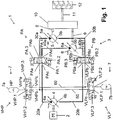
- Fig. 1 shows a dual motor hydraulic hybrid transmission 1 of an automotive vehicle (not shown).
- the vehicle may be an off-highway vehicle such as a wheel loader, for example.
- the transmission 1 comprises an internal combustion engine 2 and a hydraulic circuit 3.
- the hydraulic circuit 3 comprises a hydrostatic pump 4 drivingly engaged with the engine 2, a first hydrostatic motor 5 and a second hydrostatic motor 6.
- the hydrostatic motors 5, 6 are in fluid communication with the pump 4 through a first pump valve PA, through a second pump valve PB and through fluid lines 20a, 20b, 30a, 30b, 40a, 40b.
- a control position or spool position of the pump valves PA, PB can be controlled through electromagnetic forces or through hydraulic forces, for example.
- the pump valves PA, PB can be controlled through corresponding pilot valves (not shown).
- the pump valves PA, PB (or the corresponding pilot valves, if applicable) can be controlled through an electronic control unit (not shown) via wired or wireless electromagnetic signals.
- the fluid lines 20a, 20b, 30a, 30b, 40a, 40b connect the pump 4 and the motors 5, 6 in such a way and the valves PA, PB are configured such that by switching the valves PA, PB to corresponding control positions or control configurations the pump 4 may be selectively fluidly connected to at least one of the motors 5, 6.
- the pump 4 in one control configuration of the valves PA, PB, the pump 4 is fluidly connected to both motors 5, 6.
- the pump 4 is fluidly connected to the first motor 5 and fluidly disconnected from the second motor 6.
- the pump 4 is fluidly connected to the second motor 6 and fluidly disconnected from the first motor 5. This will be explained in more detail further below.
- a transmission shaft 8 of the first motor 5 and a transmission shaft 9 of the second motor 6 are selectively drivingly engaged with and output shaft 11 of the transmission 1 through a summing gearbox 10.
- the output shaft 11 is drivingly engaged or selectively drivingly engaged with a vehicle output 12.
- the vehicle output 12 may include at least one of a drive shaft, a vehicle axle, a final drive and one or more wheels, for example.
- the gearbox 10 is configured to selectively sum a torque provided by the motors 5, 6 at the output shaft 11. That is, the gearbox 10 may selectively simultaneously couple the output shafts 8, 9 of both motors 5, 6 to the output shaft 11.
- the gearbox 10 is further configured to selectively disengage the output shaft 11 from both motors 5, 6 at the same time.
- the gearbox 10 is further configured to selectively drivingly engage only one of the motors 5, 6 with the output shaft 11 at a given time. That is, the gearbox 10 is configured to selectively drivingly engage the first motor 5 with the output shaft 11 while disengaging the second motor 6 from the output shaft. And the gearbox 10 is configured to selectively drivingly engage the second motor 6 with the output shaft 11 while disengaging the first motor 5 from the output shaft 11.
- the transmission 1 further comprises a hydraulic accumulator assembly 7 including a high pressure accumulator 7a and a low pressure accumulator 7b.
- the accumulators 7a, 7b are configured as compressed gas accumulators.
- the accumulators 7a, 7b are configured as hollow vessels including a closed bladder filled with an inert gas such as nitrogen.
- the accumulators 7a, 7b may be pressurized by filling or partially filling the accumulator vessel with a hydraulic fluid such as oil, thereby compressing the gas contained in the bladder.
- the accumulators 7a, 7b may be de-pressurized by letting the gas contained in the bladder expand such that hydraulic fluid contained in the accumulator vessel is displaced out of the vessel, thereby creating a fluid flow.
- the accumulator assembly 7 is in fluid communication with the hydraulic circuit 3 through a high pressure accumulator valve VHP, through a low pressure accumulator valve VLP and through fluid lines 50, 60.
- the high pressure accumulator 7a is in fluid communication with the hydraulic circuit 3 through the high pressure accumulator valve VHP and through the fluid lines 50, 60
- the low pressure accumulator 7b is in fluid communication with the hydraulic circuit 3 through the low pressure accumulator valve VLP and through the fluid lines 50, 60.
- a control position or spool position of the accumulator valves VHP, VLP can be controlled through electromagnetic forces or through hydraulic forces, for example.
- the accumulator valves VHP, VLP can be controlled through corresponding pilot valves (not shown).
- the accumulator valves VHP, VLP (or the corresponding pilot valves, if applicable) can be controlled through the above mentioned electronic control unit (not shown) via wired or wireless electromagnetic signals.
- the pump 4 has a first fluid port 4a and a second fluid port 4b.
- the first motor 5 has a first fluid port 5a and a second fluid port 5b.
- the second motor 6 has a first fluid port 6a and a second fluid port 6b.
- the first pump valve PA is a 4/3-way directional valve having four fluid ports PAa, PAb, PAc, PAd and three control positions PA.1, PA.2, PA.3.
- the first fluid port PAa is fluidly connected to the fourth fluid port PAd so that hydraulic fluid may flow between the first fluid port PAa and the fourth fluid port PAd
- the second fluid port PAb is fluidly connected to the third fluid port PAc so that hydraulic fluid may flow between the second fluid port PAb and the third fluid port PAc.
- both the first fluid port PAa and the fourth fluid port PAd are fluidly disconnected from both the second fluid port PAb and from the third fluid port PAc so that no hydraulic fluid may flow between the fluid ports PAa, PAd on the one hand and the fluid ports PAb, PAc on the other hand.
- the first fluid port PAa is fluidly connected to the second fluid port PAb so that hydraulic fluid may flow between the first fluid port PAa and the second fluid port PAb
- the third fluid port PAc is fluidly connected to the fourth fluid port PAd so that hydraulic fluid may flow between the third fluid port PAc and the fourth fluid port PAd.
- both the first fluid port PAa and the second fluid port PAb are fluidly disconnected from both the third fluid port PAc and from the fourth fluid port PAd so that no hydraulic fluid may flow between the fluid ports PAa, PAb on the one hand and the fluid ports PAc, PAd on the other hand.
- the second pump valve PB is identical to the first pump valve PA. That is, the second pump valve, too, is a 4/3-way directional valve having four fluid ports PBa, PBb, PBc, PBd and three control positions PB.1, PB.2, PB.3.
- the fluid connection/disconnection between the fluid ports PBa, PBb, PBc, PBd of the second pump valve PB in the three control positions PB.1, PB.2, PB.3 of the second pump valve PB is analogous to that described with respect to the first pump valve PA. To a skilled person this is immediately apparent from the illustration of the valves PA and PB in Fig. 1 .
- the fluid line 20a fluidly connects the first fluid port 4a of the pump 4 to the third fluid port PAc of the first pump valve PA.
- the fluid line 20b fluidly connects the second fluid port 4b of the pump 4 to the first fluid port PBa of the second pump valve PB.
- the fluid line 30a fluidly connects the second fluid port PAb of the first pump valve PA to the first fluid port 5a of the first motor 5.
- the fluid line 30b fluidly connects the fourth fluid port PBd of the second pump valve PB to the second fluid port 5b of the first motor 5.
- the fluid line 40a fluidly connects the fourth fluid port PAd of the first pump valve PA to the first fluid port 6a of the first motor 6.
- the fluid line 40b fluidly connects the second fluid port PBb of the second pump valve PB to the second fluid port 6b of the first motor 6.
- the above mentioned control unit is configured to control the pump valves PA, PB such that, at a given time, both valves are in their first control position PA.1 and PB.1, in their second control position PA.2 and PB.2, or in their third control position PA.3 and PB.3.
- the pump valves PA, PB can be in one of three possible control configurations, termed P.1, P.2 and P.3 in the following.
- P.1, P.2 and P.3 in the first control configuration P.1
- the first pump valve PA is in the first control position PA.1 and the second pump valve PB is in the first control position PB.1.
- the first pump valve PA is in the second control position PA.2 and the second pump valve PB is in the second control position PB.2.
- the third control configuration P.3 the first pump valve PA is in the third control position PA.3 and the second pump valve PB is in the third control position PB.3.
- the high pressure accumulator valve VHP is a 3/3-way directional valve having three fluid ports VHPa, VHPb, VHPc and three control positions VHP.1, VHP.2, VHP.3.
- the first fluid port VHPa is fluidly connected to the second fluid port VHPb so that hydraulic fluid may flow between the first fluid port VHPa and the second fluid port VHPb.
- both the first fluid port VHPa and the second fluid port VHPb are fluidly disconnected from the third fluid port VHPc so that no hydraulic fluid may flow between the fluid ports VHPa, VHPb on the one hand and the fluid port VHPc on the other hand.
- the first fluid port VHPa is fluidly connected to the third fluid port VHPc so that hydraulic fluid may flow between the first fluid port VHPa and the third fluid port VHPc.
- both the first fluid port VHPa and the third fluid port VHPc are fluidly disconnected from the second fluid port VHPb so that no hydraulic fluid may flow between the fluid ports VHPa, VHPc on the one hand and the fluid port VHPb on the other hand.
- the low pressure accumulator valve VLP is identical to the high pressure accumulator valve VHP. That is, the low pressure accumulator valve VLP, too, is a 3/3-way directional valve having three fluid ports VLPa, VLPb, VLPc and three control positions VLP.1, VLP.2, VLP.3.
- the fluid connection/disconnection between the fluid ports VLPa, VLPb, VLPc of the low pressure accumulator valve VLP in the three control positions VLP.1, VLP.2, VLP.3 of the low pressure accumulator valve VLP is analogous to that described with respect to the high pressure accumulator valve VHP (except that VLP.2 corresponds to the right-most position and that VLP.3 corresponds to the left most position of the valve VLP in Fig. 1 ). To a skilled person this is immediately apparent from the illustration of the valves VHP and VLP in Fig. 1 .
- the first fluid port VHPa of the high pressure accumulator valve VHP is (permanently) fluidly connected to the high pressure accumulator 7a.
- the first fluid port VLPa of the low pressure accumulator valve VLP is (permanently) fluidly connected to the low pressure accumulator 7b.
- the fluid line 50 fluidly connects the second fluid port VHPb of the high pressure accumulator valve VHP and the third fluid port VLPc of the low pressure accumulator valve VLP to the first fluid port PAa of the first pump valve PA.
- the fluid line 60 fluidly connects the third fluid port VHPc of the high pressure accumulator valve VHP and the second fluid port VLPb of the low pressure accumulator valve VLP to the third fluid port PBc of the second pump valve PB.
- the above mentioned control unit is configured to control the accumulator valves VHP, VLP such that, at a given time, both valves are in their first control position VHP.1 and VLP.1, in their second control position VHP.2 and VLP.2, or in their third control position VHP.3 and VLP.3.
- the accumulator valves VHP, VLP can be in one of three possible control configurations, termed V.1, V.2 and VP.3 in the following.
- the first control configuration V.1 the high pressure accumulator valve VHP is in the first control position VHP.1 and the low pressure accumulator valve VLP is in the first control position VLP.1.
- the high pressure accumulator valve VHP is in the second control position VHP.2 and the low pressure accumulator valve VLP is in the second control position VLP.2.
- the high pressure accumulator valve VHP is in the third control position VHP.3 and the low pressure accumulator valve VLP is in the third control position VLP.3.
- T.1 P.1+V.1; T.2: P.1+V.2; T.3: P.1+V.3; T.4: P.2+V.1; T.5: P.2+V.2; T.6: P.2+V.3; T.7: P.3+V.1; T.8: P.3+V.2; T.9: P.3+V.3.
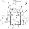
- the accumulator assembly 7 is fluidly disconnected from the hydraulic circuit 3, and the pump 4 is fluidly connected to the first motor 5 and the second motor 6 (see Fig. 1 ).
- This mode corresponds to the standard hydrostatic mode of a dual motor hydrostatic transmission. Both motors 5, 6 are driven by the pump 4.
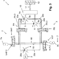
- the pump 4 is fluidly connected to both motors 5, 6.
- the accumulator assembly 7 is fluidly connected to both motors 5, 6.
- the high pressure accumulator 7a is fluidly connected to the first fluid port 5a of the first motor 5 and to the first fluid port 6a of the second motor 6, and the low pressure accumulator 7b is fluidly connected to the second fluid port 5b of the first motor 5 and to the second fluid port 6b of the second motor 6.
- This mode corresponds to a dual motor series hybrid mode.
- hydraulic fluid stored under high pressure in the high pressure accumulator 7a may be displaced from the high pressure accumulator 7a to the low pressure accumulator 7b through both motors 5, 6, thereby applying additional torque to the motors 5, 6 during a forward movement of the vehicle, for example (forward acceleration).
- the accumulators 7a, 7b may be used to decelerate the vehicle during a rearward movement of the vehicle (rearward deceleration).
- the pump 4 is again fluidly connected to both motors 5, 6.
- the accumulator assembly 7 is fluidly connected to both motors 5, 6.
- the high pressure accumulator 7a is fluidly connected to the second fluid port 5b of the first motor 5 and to the second fluid port 6b of the second motor 6, and the low pressure accumulator 7b is fluidly connected to the first fluid port 5a of the first motor 5 and to the first fluid port 6a of the second motor 6.
- this mode corresponds to a dual motor series hybrid mode.
- the accumulator assembly 7 may be used to decelerate the vehicle during a forward movement of the vehicle (forward deceleration) or to accelerate the vehicle during a rearward movement of the vehicle (rearward acceleration).
- the accumulator assembly 7 is again fluidly disconnected from the hydraulic circuit 3.
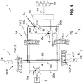
- the pump 4 is fluidly connected to the first motor 5 and fluidly disconnected from the second motor 6. This mode corresponds to the standard hydrostatic mode of a single motor hydrostatic transmission using the first motor 5 only.
- the pump 4 is fluidly connected to the first motor 5 and fluidly disconnected from the second motor 6.
- the accumulator assembly 7 is fluidly connected to the second motor 6 and fluidly disconnected from the first motor 5.
- the high pressure accumulator 7a is fluidly connected to the first fluid port 6a of the second motor 6, and the low pressure accumulator 7b is fluidly connected to the second fluid port 6b of the second motor 6.
- the (sub)circuit formed by the pump 4, the first motor 5 and the fluid lines 20a, 30a, 20b, 30b is fluidly isolated from the (sub)circuit formed by the accumulators 7a, 7b, the second motor 6 and the fluid lines 50, 60, 40a, 40b.
- the first motor 5 is powered only by the pump 4 and the second motor 6 is powered only by the accumulator assembly 7.
- the torque/power provided by the pump 4 and the torque/power provided by the accumulator assembly 7 is only summed in the gearbox 10. Therefore, the transmission 1 can be switched into this mode even if there is a pressure mismatch between the hydraulic pressure in the hydraulic circuit 3 and the hydraulic pressure in the accumulator assembly 7.
- This mode corresponds to a parallel mode and may be used during forward acceleration, for example.
- the accumulator assembly 7 is fluidly disconnected from the hydraulic circuit 3.
- the pump 4 is fluidly connected to the second motor 6 and fluidly disconnected from the first motor 5. This mode corresponds to the standard hydrostatic mode of a single motor hydrostatic transmission using the second motor 6 only.
- This mode is similar to the mode associated with the configuration T.5 described above.
- the roles of the first motor 5 and the second motor 6 are interchanged.
- the pump 4 is now fluidly connected to the second motor 6 and fluidly disconnected from the first motor 5.
- the accumulator assembly 7 is fluidly connected to the first motor 5 and fluidly disconnected from the second motor 6.
- the high pressure accumulator 7a is fluidly connected to the first fluid port 5a of the first motor 5
- the low pressure accumulator 7b is fluidly connected to the second fluid port 5b of the first motor 5.
- the (sub)circuit formed by the pump 4, the second motor 6 and the fluid lines 20a, 40a, 20b, 40b is fluidly isolated from the (sub)circuit formed by the accumulators 7a, 7b, the first motor 5 and the fluid lines 50, 60, 30a, 30b.
- the first motor 5 is powered only by the accumulator assembly 7 and the second motor 6 is powered only by the pump 4.
- the torque/power provided by the pump 4 and the torque/power provided by the accumulator assembly 7 is only summed in the gearbox 10. Therefore, the transmission 1 can be switched into this mode even if there is a pressure mismatch between the hydraulic pressure in the hydraulic circuit 3 and the hydraulic pressure in the accumulator assembly 7.
- This mode corresponds to a parallel mode and may be used during forward acceleration, for example.
- Fig. 5 shows a dual motor hydraulic hybrid transmission 1' which is a variant of the transmission 1 of Figs. 1-4 .
- the embodiment of Fig. 5 differs from the embodiment of Figs. 1-4 in that the accumulators 7a, 7b can be selectively fluidly connected to the motors 5, 6 mostly independently of the control configuration of the pump valves PA, PB.
- each of the pump valves PA, PB is realized with two 2/2 valves. More specifically, valve PA is realized with the two valves PA.A, PA.B, and valve PB is realized with the two valves PB.A and PB.B.
- the pump 4 can be selectively fluidly connected to both motors 5, 6 or to only one of the motors 5, 6.
- the pump 4 can be fluidly connected to both motors 5, 6 by switching the first pump valves PA.A and PA.B to the first control position PA.A.1 and PA.B.1 (as shown in Fig. 5 ), respectively, and by simultaneously switching the second pump valves PB.A and PB.B to the first control position PB.A.1 and PB.B.1, respectively.
- the pump 4 can be fluidly connected to the first motor 5 and, at the same time, fluidly disconnected from the second motor 6 by switching each of the pump valves PA.A, PA.B, PB.A and PB.B to their respective control positions PA.A.1, PA.B.2, PB.A.2 and PB.B.2.
- the pump 4 can be fluidly connected to the second motor 6 and, at the same time, fluidly disconnected from the first motor 5 by switching each of the pump valves PA.A, PA.B, PB.A and PB.B to their respective control positions PA.A.2, PA.B.1, PB.A.1 and PB.B.2.
- the accumulator assembly 7 comprising the high pressure accumulator 7a and the low pressure accumulator 7b can be selectively fluidly connected to the hydraulic circuit using 2/2 valves VHP1, VHP2, VHP3, VHP4, VHP5, VHP6, VLP1, VLP2, VLP3, VLP4, VLP5, VLP6.
- Each of the valves VHP1...6, VLP1...6 is a 2/2-way shut-off valve having an open position and a closed position.
- the high pressure accumulator 7a can be selectively fluidly connected to each of the fluid lines 20a, 30a, 40a, 20b, 30b, 40b through a set of six high pressure accumulator valves VHP1, VHP2, VHP3, VHP4, VHP5, VHP6.
- Valve VHP1 when it is in the open position, selectively fluidly connects the high-pressure accumulator 7a, via its fluid line 100, to the fluid line 20a. When it is in the closed position, it isolates fluid line 20a from the high-pressure accumulator 7a.
- Valve VHP2 when it is in the open position, selectively fluidly connects the high-pressure accumulator 7a, via its fluid line 100, to the fluid line 20b. When it is in the closed position, it isolates fluid line 20b from the high-pressure accumulator 7a.
- Valve VHP3 when it is in the open position, selectively fluidly connects the high-pressure accumulator 7a, via its fluid line 100, to the fluid line 30a. When it is in the closed position, it isolates fluid line 30a from the high-pressure accumulator 7a.
- Valve VHP4 when it is in the open position, selectively fluidly connects the high-pressure accumulator 7a, via its fluid line 100, to the fluid line 40a. When it is in the closed position, it isolates fluid line 40a from the high-pressure accumulator 7a.
- Valve VHP5 when it is in the open position, selectively fluidly connects the high-pressure accumulator 7a, via its fluid line 100, to the fluid line 40b. When it is in the closed position, it isolates fluid line 40b from the high-pressure accumulator 7a.
- Valve VHP6 when it is in the open position, selectively fluidly connects the high-pressure accumulator 7a, via its fluid line 100, to the fluid line 30b. When it is in the closed position, it isolates fluid line 30b from the high-pressure accumulator 7a.
- valves VHP1, VHP2, VHP3, VHP4, VHP5, VHP6 can be used to selectively one of: disconnect the high pressure accumulator 7a from the hydraulic circuit 3; fluidly connect the high pressure accumulator 7a to the first fluid port 5a of the first motor 5; fluidly connect the high pressure accumulator 7a to the first fluid port 6a of the second motor 6; fluidly connect the high pressure accumulator 7a to the second fluid port 5b of the first motor 5; fluidly connect the high pressure accumulator 7a to the second fluid port 6b of the second motor 6; fluidly connect the low pressure accumulator 7b to the first fluid port 5a of the first motor 5 and to the first fluid port 6a of the second motor 6; and fluidly connect the low pressure accumulator 7b to the second fluid port 5b of the first motor 5 and to the second fluid port 6b of the second motor 6.
- the high pressure accumulator 7a may be simultaneously fluidly connected to the first fluid ports 5a, 6a of the first motor 5 and of the second motor 6, respectively, through valve VHP1.
- the high pressure accumulator 7a may be simultaneously fluidly connected to the second fluid ports 5b, 6b of the first motor 5 and of the second motor 6, respectively, through valve VHP2.
- the low pressure accumulator 7b can be selectively fluidly connected to each of the fluid lines 20a, 20b, 30a, 30b, 40a, 40b through a set of low pressure accumulator valves VLP1, VLP2, VLP3, VLP4, VLP5, VLP6.
- Valve VLP1 when it is in the open position, selectively fluidly connects the high-pressure accumulator 7a, via its fluid line 100, to the fluid line 20a. When it is in the closed position, it isolates fluid line 20a from the high-pressure accumulator 7a.
- Valve VLP2 when it is in the open position, selectively fluidly connects the high-pressure accumulator 7a, via its fluid line 100, to the fluid line 20b. When it is in the closed position, it isolates fluid line 20b from the high-pressure accumulator 7a.
- Valve VLP3 when it is in the open position, selectively fluidly connects the high-pressure accumulator 7a, via its fluid line 100, to the fluid line 30b. When it is in the closed position, it isolates fluid line 30b from the high-pressure accumulator 7a.
- Valve VLP4 when it is in the open position, selectively fluidly connects the high-pressure accumulator 7a, via its fluid line 100, to the fluid line 40b. When it is in the closed position, it isolates fluid line 40b from the high-pressure accumulator 7a.
- Valve VLP5 when it is in the open position, selectively fluidly connects the high-pressure accumulator 7a, via its fluid line 100, to the fluid line 40a. When it is in the closed position, it isolates fluid line 40a from the high-pressure accumulator 7a.
- Valve VLP6 when it is in the open position, selectively fluidly connects the high-pressure accumulator 7a, via its fluid line 100, to the fluid line 30a. When it is in the closed position, it isolates fluid line 30a from the high-pressure accumulator 7a.
- valves VLP1, VLP2, VLP3, VLP4, VLP5, VLP6 can be used to selectively one of: disconnect the low pressure accumulator 7b from the hydraulic circuit 3; fluidly connect the low pressure accumulator 7b to the first fluid port 5a of the first motor 5; fluidly connect the low pressure accumulator 7b to the first fluid port 6a of the second motor 6; fluidly connect the low pressure accumulator 7b to the second fluid port 5b of the first motor 5; fluidly connect the low pressure accumulator 7b to the second fluid port 6b of the second motor 6; fluidly connect the low pressure accumulator 7b to the first fluid port 5a of the first motor 5 and to the first fluid port 6a of the second motor 6; and fluidly connect the low pressure accumulator 7b to the second fluid port 5b of the first motor 5 and to the second fluid port 6b of the second motor 6.
- the low pressure accumulator 7b may be simultaneously fluidly connected to the first fluid ports 5a, 6a of the first motor 5 and of the second motor 6, respectively, through valve VLP1.
- the pump valves PA.A, PA.B, PB.A, PB.B are switched to their first control position PA.A.1, PA.B.1, PB.A.1, PB.B.1, respectively, the low pressure accumulator 7b may be simultaneously fluidly connected to the second fluid ports 5b, 6b of the first motor 5 and the second motor 6 through valve VLP2.
- two extra 2/2 valves e.g. VHP and VLP
- VHP and VLP could be used to isolate accumulators 7a and 7b from lines 100 and 200 respectively, for extra safety and to reduce leakage.
- the advantage of the presently proposed transmission with respect to the simple series hybrid mode is the ability to sum torque at the mechanical transmission input at any level of accumulator pressure, thus decoupling the accumulator pressure from the road load. In addition, it allows hydraulic disconnection of one of the two motors even in standard hydrostatic mode, thus reducing losses.
- Figs. 1-4 show the basic operating modes and the operation of the hydraulic control devices to obtain each mode.
- the 3/3 accumulator valves resolve the function of connecting each accumulator to the high pressure line of the hydraulic circuit 3, the low pressure line of the hydraulic circuit 3 or neither, while the 4/3 line valves switch between series and parallel modes.
- the series mode corresponds to the center position, when both motors are connected to the same pressure source, while the parallel mode is realized by connecting the pump to the first motor and the accumulator to the second motor.
- switching the accumulator valves changes the pressure acting on the second motor (equivalent to switching from boosting vs. regen).
Landscapes
- Engineering & Computer Science (AREA)
- General Engineering & Computer Science (AREA)
- Mechanical Engineering (AREA)
- Chemical & Material Sciences (AREA)
- Combustion & Propulsion (AREA)
- Transportation (AREA)
- Control Of Fluid Gearings (AREA)
- Fluid-Pressure Circuits (AREA)
- Motor Power Transmission Devices (AREA)
- Arrangement Or Mounting Of Propulsion Units For Vehicles (AREA)
- Operation Control Of Excavators (AREA)
Applications Claiming Priority (2)
| Application Number | Priority Date | Filing Date | Title |
|---|---|---|---|
| US201461935642P | 2014-02-04 | 2014-02-04 | |
| PCT/EP2015/052215 WO2015117964A1 (en) | 2014-02-04 | 2015-02-03 | Series parallel hydraulic hybrid architecture |
Publications (2)
| Publication Number | Publication Date |
|---|---|
| EP3102853A1 EP3102853A1 (en) | 2016-12-14 |
| EP3102853B1 true EP3102853B1 (en) | 2019-11-06 |
Family
ID=52465360
Family Applications (1)
| Application Number | Title | Priority Date | Filing Date |
|---|---|---|---|
| EP15703768.0A Active EP3102853B1 (en) | 2014-02-04 | 2015-02-03 | Series parallel hydraulic hybrid architecture |
Country Status (7)
| Country | Link |
|---|---|
| US (1) | US10215276B2 (enExample) |
| EP (1) | EP3102853B1 (enExample) |
| JP (1) | JP6583965B2 (enExample) |
| KR (1) | KR20160128321A (enExample) |
| CN (1) | CN105940248B (enExample) |
| AU (1) | AU2015215028B2 (enExample) |
| WO (1) | WO2015117964A1 (enExample) |
Families Citing this family (14)
| Publication number | Priority date | Publication date | Assignee | Title |
|---|---|---|---|---|
| JP6509881B2 (ja) | 2014-02-04 | 2019-05-08 | ダナ イタリア エスピーエー | 直列油圧式ハイブリッドシステム及び直列油圧式ハイブリッドシステムを操作する方法 |
| CN105980712B (zh) | 2014-02-04 | 2018-06-01 | 意大利德纳股份有限公司 | 蓄能器架 |
| JP6583965B2 (ja) | 2014-02-04 | 2019-10-02 | ダナ イタリア エスピーエー | 直並列油圧式ハイブリット構造 |
| CN106163849B (zh) | 2014-02-04 | 2019-01-18 | 意大利德纳股份有限公司 | 功率提升中枢 |
| EP3002147A1 (en) * | 2014-10-02 | 2016-04-06 | Dana Italia S.p.A. | Dual drive driveline |
| DE102015006321A1 (de) * | 2015-05-16 | 2016-11-17 | Hydac System Gmbh | Hydrostatischer Antrieb |
| CN107856576A (zh) * | 2017-10-24 | 2018-03-30 | 西南交通大学 | 一种车辆电液混合驱动系统 |
| CN111306279B (zh) * | 2020-02-21 | 2021-08-03 | 江苏大学 | 一种单泵控双马达机械液压复合传动装置 |
| US11885103B2 (en) * | 2020-05-04 | 2024-01-30 | Volvo Construction Equipment Ab | Power system for a working machine and corresponding operation method |
| CN112681418A (zh) * | 2021-01-13 | 2021-04-20 | 长沙理工大学 | 一种挖掘机工作机构内置垂直分布式液压储能装置 |
| DE102021127442A1 (de) * | 2021-10-22 | 2023-04-27 | Hamm Ag | Bodenbearbeitungsmaschine und Verfahren zum Betreiben einer Bodenbearbeitungsmaschine |
| CN113815398B (zh) * | 2021-10-28 | 2023-05-26 | 华侨大学 | 一种轮式移动机械及其并联式油电液混合驱动系统和驱动方法 |
| US12428811B2 (en) * | 2021-11-19 | 2025-09-30 | Robert Bosch Gmbh | Construction machine with active ride control |
| KR20230151122A (ko) | 2022-04-22 | 2023-11-01 | 현대자동차주식회사 | 하이브리드 자동차 및 그를 위한 변속 제어 방법 |
Family Cites Families (49)
| Publication number | Priority date | Publication date | Assignee | Title |
|---|---|---|---|---|
| US4098083A (en) * | 1977-04-20 | 1978-07-04 | Carman Vincent Earl | Hydraulic energy storage multi-speed transmission |
| DE3625141A1 (de) | 1986-07-25 | 1988-02-04 | Man Nutzfahrzeuge Gmbh | Antriebseinrichtung fuer ein fahrzeug mit notfahraggregat |
| US4760697A (en) | 1986-08-13 | 1988-08-02 | National Research Council Of Canada | Mechanical power regeneration system |
| DE4307616C2 (de) | 1993-03-08 | 1996-06-27 | Mannesmann Ag | Hydrostatisch-mechanisches Getriebe |
| US5579640A (en) | 1995-04-27 | 1996-12-03 | The United States Of America As Represented By The Administrator Of The Environmental Protection Agency | Accumulator engine |
| US5887674A (en) | 1995-10-11 | 1999-03-30 | The United States Of America As Represented By The Administrator Of The U.S. Environmental Protection Agency | Continuously smooth transmission |
| DE19931208B4 (de) | 1999-07-06 | 2005-06-02 | Gustav Magenwirth Gmbh & Co. Kg | Geschlossenes hydraulisches Betätigungssystem |
| US6719080B1 (en) | 2000-01-10 | 2004-04-13 | The United States Of America As Represented By The Administrator Of The Environmental Protection Agency | Hydraulic hybrid vehicle |
| US7337869B2 (en) | 2000-01-10 | 2008-03-04 | The United States Of America As Represented By The Administrator Of The United States Environmental Protection Agency | Hydraulic hybrid vehicle with integrated hydraulic drive module and four-wheel-drive, and method of operation thereof |
| US6622484B2 (en) | 2001-02-02 | 2003-09-23 | Caterpillar Inc. | Hystat/split torque modulation |
| US6732828B1 (en) | 2002-10-22 | 2004-05-11 | Robert Abend | Hydraulically driven vehicle |
| WO2007035997A1 (en) | 2005-09-28 | 2007-04-05 | Permo-Drive Research And Development Pty Ltd | Hydraulic circuit for a energy regenerative drive system |
| DE102006060014B4 (de) | 2005-12-20 | 2009-05-14 | Bosch Rexroth Aktiengesellschaft | Hydrostatischer Antrieb mit Rückgewinnung von Bremsenergie |
| DE102005061991A1 (de) | 2005-12-23 | 2007-07-05 | Bosch Rexroth Aktiengesellschaft | Hydrostatischer Antrieb |
| DE102006017581A1 (de) * | 2006-03-02 | 2007-09-13 | Robert Bosch Gmbh | Hydrostatischer Mehrmotorenantrieb |
| US7669414B2 (en) | 2006-03-28 | 2010-03-02 | Parker-Hannifin Corporation | Hydraulic energy recovery system with dual-powered auxiliary hydraulics |
| DE102006019672B4 (de) | 2006-04-27 | 2013-11-14 | Robert Bosch Gmbh | Hydraulikfluidspeicher mit integrierter Hochdruck- und Niederdruckkammer |
| JP4628309B2 (ja) * | 2006-05-18 | 2011-02-09 | トヨタ自動車株式会社 | 車両およびその制御方法 |
| GB0614930D0 (en) * | 2006-07-27 | 2006-09-06 | Arternis Intelligent Power Ltd | Hydrostatic regenerative drive system |
| CN201176978Y (zh) | 2008-04-16 | 2009-01-07 | 长沙矿山研究院 | 一种深海水压储能式液压动力源 |
| DE102008062836B3 (de) | 2008-12-23 | 2010-08-05 | Hydac Technology Gmbh | Hydrostatisches Antriebssystem |
| US8616323B1 (en) | 2009-03-11 | 2013-12-31 | Echogen Power Systems | Hybrid power systems |
| JP2011040244A (ja) * | 2009-08-10 | 2011-02-24 | Sony Corp | 発光素子 |
| DE102009056153A1 (de) | 2009-11-27 | 2011-06-01 | Robert Bosch Gmbh | Antriebssystem mit multifunktionaler Energierückgewinnung und Verfahren zu dessen Betrieb |
| US9032723B2 (en) | 2010-03-09 | 2015-05-19 | The United States Of America, As Represented By The Administrator Of The U.S. Environmental Protection Agency | Hydraulic hybrid vehicle with safe and efficient hydrostatic operation |
| CN103249950B (zh) * | 2010-10-15 | 2015-07-22 | 伊顿公司 | 用于工业过程的混合液压系统 |
| FR2971741B1 (fr) | 2011-02-17 | 2014-06-13 | Peugeot Citroen Automobiles Sa | Chaine de traction d'un vehicule hybride utilisant une energie hydraulique |
| DE102011005356A1 (de) | 2011-03-10 | 2012-09-13 | Robert Bosch Gmbh | Serieller Hydraulikhybridantriebsstrang |
| WO2012125798A1 (en) | 2011-03-16 | 2012-09-20 | Parker Hannifin Corporation | Start control system using single hydraulic pump |
| US20120233991A1 (en) | 2011-03-16 | 2012-09-20 | Purdue Research Foundtion | Multi-function machines, hydraulic systems therefor, and methods for their operation |
| US10233949B2 (en) | 2011-03-21 | 2019-03-19 | Dana Belgium N.V. | Accumulator assisted hydrostatic driveline and optimization method thereof |
| EP2688761B1 (en) * | 2011-03-21 | 2015-12-16 | Dana Belgium N.V. | Accumulator assisted hydrostatic driveline and optimization method thereof |
| US9057389B2 (en) * | 2011-09-30 | 2015-06-16 | Caterpillar Inc. | Meterless hydraulic system having multi-actuator circuit |
| DE102011055178B4 (de) | 2011-11-09 | 2021-03-04 | Linde Hydraulics Gmbh & Co. Kg | Hydrostatischer Fahrantrieb einer allradgetriebenen Arbeitsmaschine |
| US9096115B2 (en) | 2011-11-17 | 2015-08-04 | Caterpillar Inc. | System and method for energy recovery |
| DE102011119309A1 (de) | 2011-11-24 | 2013-05-29 | Robert Bosch Gmbh | Hydraulischer Fahrantrieb mit geschlossenem hydraulischem Kreislauf und Verfahren zum Betrieb eines derartigen Fahrantriebs |
| CN102518169B (zh) | 2011-12-27 | 2014-06-18 | 山重建机(济宁)有限公司 | 一种混合动力液压挖掘机 |
| FR2987002B1 (fr) | 2012-02-16 | 2014-03-21 | Peugeot Citroen Automobiles Sa | Circuit hydraulique equipant un vehicule automobile et groupe de propulsion hybride hydraulique comprenant un tel circuit hydraulique |
| DE102012008192A1 (de) * | 2012-04-26 | 2013-10-31 | Deutz Aktiengesellschaft | Hydraulikhybrid |
| CN102734237B (zh) | 2012-07-16 | 2015-07-15 | 北京市三一重机有限公司 | 一种蓄能器系统和水泵系统 |
| US9765502B2 (en) | 2013-06-03 | 2017-09-19 | Volvo Construction Equipment Ab | Power system for a working machine |
| JP6583965B2 (ja) | 2014-02-04 | 2019-10-02 | ダナ イタリア エスピーエー | 直並列油圧式ハイブリット構造 |
| WO2015117960A1 (en) | 2014-02-04 | 2015-08-13 | Dana Italia Spa | Hybrid powermode with series hybrid |
| EP2913212A1 (en) | 2014-02-28 | 2015-09-02 | DANA ITALIA S.p.A | Dual mode hybrid hydrostatic driveline |
| FR3019612B1 (fr) | 2014-04-02 | 2016-04-08 | Poclain Hydraulics Ind | Systeme d'assistance hydraulique |
| EP3040226B1 (en) | 2014-12-30 | 2020-07-08 | Dana Belgium N.V. | Hydraulic Hybrid Powertrain |
| FR3016671B1 (fr) | 2014-08-26 | 2016-01-22 | Poclain Hydraulics Ind | Dispositif de repartition d'huile avec clapet anti-retour |
| EP3002147A1 (en) | 2014-10-02 | 2016-04-06 | Dana Italia S.p.A. | Dual drive driveline |
| CN107000564B (zh) | 2014-10-27 | 2019-12-24 | 伊顿智能动力有限公司 | 具有静流体选择的液压混合推进回路以及操作方法 |
-
2015
- 2015-02-03 JP JP2016541716A patent/JP6583965B2/ja not_active Expired - Fee Related
- 2015-02-03 KR KR1020167024079A patent/KR20160128321A/ko not_active Withdrawn
- 2015-02-03 WO PCT/EP2015/052215 patent/WO2015117964A1/en not_active Ceased
- 2015-02-03 AU AU2015215028A patent/AU2015215028B2/en not_active Ceased
- 2015-02-03 EP EP15703768.0A patent/EP3102853B1/en active Active
- 2015-02-03 US US14/999,974 patent/US10215276B2/en active Active
- 2015-02-03 CN CN201580006877.4A patent/CN105940248B/zh not_active Expired - Fee Related
Non-Patent Citations (1)
| Title |
|---|
| None * |
Also Published As
| Publication number | Publication date |
|---|---|
| AU2015215028A1 (en) | 2016-07-07 |
| EP3102853A1 (en) | 2016-12-14 |
| JP6583965B2 (ja) | 2019-10-02 |
| US20160341309A1 (en) | 2016-11-24 |
| KR20160128321A (ko) | 2016-11-07 |
| JP2017511863A (ja) | 2017-04-27 |
| CN105940248B (zh) | 2018-08-14 |
| WO2015117964A1 (en) | 2015-08-13 |
| CN105940248A (zh) | 2016-09-14 |
| AU2015215028B2 (en) | 2018-07-12 |
| US10215276B2 (en) | 2019-02-26 |
Similar Documents
| Publication | Publication Date | Title |
|---|---|---|
| EP3102853B1 (en) | Series parallel hydraulic hybrid architecture | |
| EP3102834B1 (en) | Travel and work functions integrated into a hydraulic hybrid system | |
| CN104203799B (zh) | 用于工作机器的推进回路和工作回路组合 | |
| EP3003756B1 (en) | A working machine power system | |
| US10464409B2 (en) | Hydraulic hybrid powertrain | |
| EP3102470B1 (en) | Hybrid powermode with series hybrid | |
| US10214102B2 (en) | Dual drive hybrid driveline | |
| US10220697B2 (en) | Powerboost hub |
Legal Events
| Date | Code | Title | Description |
|---|---|---|---|
| PUAI | Public reference made under article 153(3) epc to a published international application that has entered the european phase |
Free format text: ORIGINAL CODE: 0009012 |
|
| STAA | Information on the status of an ep patent application or granted ep patent |
Free format text: STATUS: REQUEST FOR EXAMINATION WAS MADE |
|
| 17P | Request for examination filed |
Effective date: 20160905 |
|
| AK | Designated contracting states |
Kind code of ref document: A1 Designated state(s): AL AT BE BG CH CY CZ DE DK EE ES FI FR GB GR HR HU IE IS IT LI LT LU LV MC MK MT NL NO PL PT RO RS SE SI SK SM TR |
|
| AX | Request for extension of the european patent |
Extension state: BA ME |
|
| DAX | Request for extension of the european patent (deleted) | ||
| STAA | Information on the status of an ep patent application or granted ep patent |
Free format text: STATUS: EXAMINATION IS IN PROGRESS |
|
| 17Q | First examination report despatched |
Effective date: 20170703 |
|
| GRAJ | Information related to disapproval of communication of intention to grant by the applicant or resumption of examination proceedings by the epo deleted |
Free format text: ORIGINAL CODE: EPIDOSDIGR1 |
|
| GRAP | Despatch of communication of intention to grant a patent |
Free format text: ORIGINAL CODE: EPIDOSNIGR1 |
|
| GRAP | Despatch of communication of intention to grant a patent |
Free format text: ORIGINAL CODE: EPIDOSNIGR1 |
|
| STAA | Information on the status of an ep patent application or granted ep patent |
Free format text: STATUS: GRANT OF PATENT IS INTENDED |
|
| INTG | Intention to grant announced |
Effective date: 20190517 |
|
| INTG | Intention to grant announced |
Effective date: 20190522 |
|
| GRAS | Grant fee paid |
Free format text: ORIGINAL CODE: EPIDOSNIGR3 |
|
| GRAA | (expected) grant |
Free format text: ORIGINAL CODE: 0009210 |
|
| STAA | Information on the status of an ep patent application or granted ep patent |
Free format text: STATUS: THE PATENT HAS BEEN GRANTED |
|
| AK | Designated contracting states |
Kind code of ref document: B1 Designated state(s): AL AT BE BG CH CY CZ DE DK EE ES FI FR GB GR HR HU IE IS IT LI LT LU LV MC MK MT NL NO PL PT RO RS SE SI SK SM TR |
|
| REG | Reference to a national code |
Ref country code: GB Ref legal event code: FG4D |
|
| REG | Reference to a national code |
Ref country code: CH Ref legal event code: EP Ref country code: AT Ref legal event code: REF Ref document number: 1199158 Country of ref document: AT Kind code of ref document: T Effective date: 20191115 |
|
| REG | Reference to a national code |
Ref country code: IE Ref legal event code: FG4D |
|
| REG | Reference to a national code |
Ref country code: DE Ref legal event code: R096 Ref document number: 602015041075 Country of ref document: DE |
|
| REG | Reference to a national code |
Ref country code: NL Ref legal event code: MP Effective date: 20191106 |
|
| REG | Reference to a national code |
Ref country code: LT Ref legal event code: MG4D |
|
| PG25 | Lapsed in a contracting state [announced via postgrant information from national office to epo] |
Ref country code: PT Free format text: LAPSE BECAUSE OF FAILURE TO SUBMIT A TRANSLATION OF THE DESCRIPTION OR TO PAY THE FEE WITHIN THE PRESCRIBED TIME-LIMIT Effective date: 20200306 Ref country code: SE Free format text: LAPSE BECAUSE OF FAILURE TO SUBMIT A TRANSLATION OF THE DESCRIPTION OR TO PAY THE FEE WITHIN THE PRESCRIBED TIME-LIMIT Effective date: 20191106 Ref country code: NL Free format text: LAPSE BECAUSE OF FAILURE TO SUBMIT A TRANSLATION OF THE DESCRIPTION OR TO PAY THE FEE WITHIN THE PRESCRIBED TIME-LIMIT Effective date: 20191106 Ref country code: LV Free format text: LAPSE BECAUSE OF FAILURE TO SUBMIT A TRANSLATION OF THE DESCRIPTION OR TO PAY THE FEE WITHIN THE PRESCRIBED TIME-LIMIT Effective date: 20191106 Ref country code: LT Free format text: LAPSE BECAUSE OF FAILURE TO SUBMIT A TRANSLATION OF THE DESCRIPTION OR TO PAY THE FEE WITHIN THE PRESCRIBED TIME-LIMIT Effective date: 20191106 Ref country code: PL Free format text: LAPSE BECAUSE OF FAILURE TO SUBMIT A TRANSLATION OF THE DESCRIPTION OR TO PAY THE FEE WITHIN THE PRESCRIBED TIME-LIMIT Effective date: 20191106 Ref country code: GR Free format text: LAPSE BECAUSE OF FAILURE TO SUBMIT A TRANSLATION OF THE DESCRIPTION OR TO PAY THE FEE WITHIN THE PRESCRIBED TIME-LIMIT Effective date: 20200207 Ref country code: FI Free format text: LAPSE BECAUSE OF FAILURE TO SUBMIT A TRANSLATION OF THE DESCRIPTION OR TO PAY THE FEE WITHIN THE PRESCRIBED TIME-LIMIT Effective date: 20191106 Ref country code: BG Free format text: LAPSE BECAUSE OF FAILURE TO SUBMIT A TRANSLATION OF THE DESCRIPTION OR TO PAY THE FEE WITHIN THE PRESCRIBED TIME-LIMIT Effective date: 20200206 Ref country code: NO Free format text: LAPSE BECAUSE OF FAILURE TO SUBMIT A TRANSLATION OF THE DESCRIPTION OR TO PAY THE FEE WITHIN THE PRESCRIBED TIME-LIMIT Effective date: 20200206 |
|
| PGFP | Annual fee paid to national office [announced via postgrant information from national office to epo] |
Ref country code: IT Payment date: 20200220 Year of fee payment: 6 |
|
| PG25 | Lapsed in a contracting state [announced via postgrant information from national office to epo] |
Ref country code: RS Free format text: LAPSE BECAUSE OF FAILURE TO SUBMIT A TRANSLATION OF THE DESCRIPTION OR TO PAY THE FEE WITHIN THE PRESCRIBED TIME-LIMIT Effective date: 20191106 Ref country code: IS Free format text: LAPSE BECAUSE OF FAILURE TO SUBMIT A TRANSLATION OF THE DESCRIPTION OR TO PAY THE FEE WITHIN THE PRESCRIBED TIME-LIMIT Effective date: 20200306 Ref country code: HR Free format text: LAPSE BECAUSE OF FAILURE TO SUBMIT A TRANSLATION OF THE DESCRIPTION OR TO PAY THE FEE WITHIN THE PRESCRIBED TIME-LIMIT Effective date: 20191106 |
|
| PG25 | Lapsed in a contracting state [announced via postgrant information from national office to epo] |
Ref country code: AL Free format text: LAPSE BECAUSE OF FAILURE TO SUBMIT A TRANSLATION OF THE DESCRIPTION OR TO PAY THE FEE WITHIN THE PRESCRIBED TIME-LIMIT Effective date: 20191106 |
|
| PG25 | Lapsed in a contracting state [announced via postgrant information from national office to epo] |
Ref country code: RO Free format text: LAPSE BECAUSE OF FAILURE TO SUBMIT A TRANSLATION OF THE DESCRIPTION OR TO PAY THE FEE WITHIN THE PRESCRIBED TIME-LIMIT Effective date: 20191106 Ref country code: DK Free format text: LAPSE BECAUSE OF FAILURE TO SUBMIT A TRANSLATION OF THE DESCRIPTION OR TO PAY THE FEE WITHIN THE PRESCRIBED TIME-LIMIT Effective date: 20191106 Ref country code: EE Free format text: LAPSE BECAUSE OF FAILURE TO SUBMIT A TRANSLATION OF THE DESCRIPTION OR TO PAY THE FEE WITHIN THE PRESCRIBED TIME-LIMIT Effective date: 20191106 Ref country code: CZ Free format text: LAPSE BECAUSE OF FAILURE TO SUBMIT A TRANSLATION OF THE DESCRIPTION OR TO PAY THE FEE WITHIN THE PRESCRIBED TIME-LIMIT Effective date: 20191106 Ref country code: ES Free format text: LAPSE BECAUSE OF FAILURE TO SUBMIT A TRANSLATION OF THE DESCRIPTION OR TO PAY THE FEE WITHIN THE PRESCRIBED TIME-LIMIT Effective date: 20191106 |
|
| REG | Reference to a national code |
Ref country code: DE Ref legal event code: R097 Ref document number: 602015041075 Country of ref document: DE |
|
| REG | Reference to a national code |
Ref country code: AT Ref legal event code: MK05 Ref document number: 1199158 Country of ref document: AT Kind code of ref document: T Effective date: 20191106 |
|
| PG25 | Lapsed in a contracting state [announced via postgrant information from national office to epo] |
Ref country code: SK Free format text: LAPSE BECAUSE OF FAILURE TO SUBMIT A TRANSLATION OF THE DESCRIPTION OR TO PAY THE FEE WITHIN THE PRESCRIBED TIME-LIMIT Effective date: 20191106 Ref country code: SM Free format text: LAPSE BECAUSE OF FAILURE TO SUBMIT A TRANSLATION OF THE DESCRIPTION OR TO PAY THE FEE WITHIN THE PRESCRIBED TIME-LIMIT Effective date: 20191106 |
|
| PLBE | No opposition filed within time limit |
Free format text: ORIGINAL CODE: 0009261 |
|
| STAA | Information on the status of an ep patent application or granted ep patent |
Free format text: STATUS: NO OPPOSITION FILED WITHIN TIME LIMIT |
|
| REG | Reference to a national code |
Ref country code: CH Ref legal event code: PL |
|
| 26N | No opposition filed |
Effective date: 20200807 |
|
| GBPC | Gb: european patent ceased through non-payment of renewal fee |
Effective date: 20200206 |
|
| REG | Reference to a national code |
Ref country code: BE Ref legal event code: MM Effective date: 20200229 |
|
| PG25 | Lapsed in a contracting state [announced via postgrant information from national office to epo] |
Ref country code: MC Free format text: LAPSE BECAUSE OF FAILURE TO SUBMIT A TRANSLATION OF THE DESCRIPTION OR TO PAY THE FEE WITHIN THE PRESCRIBED TIME-LIMIT Effective date: 20191106 Ref country code: LU Free format text: LAPSE BECAUSE OF NON-PAYMENT OF DUE FEES Effective date: 20200203 |
|
| PG25 | Lapsed in a contracting state [announced via postgrant information from national office to epo] |
Ref country code: CH Free format text: LAPSE BECAUSE OF NON-PAYMENT OF DUE FEES Effective date: 20200229 Ref country code: SI Free format text: LAPSE BECAUSE OF FAILURE TO SUBMIT A TRANSLATION OF THE DESCRIPTION OR TO PAY THE FEE WITHIN THE PRESCRIBED TIME-LIMIT Effective date: 20191106 Ref country code: AT Free format text: LAPSE BECAUSE OF FAILURE TO SUBMIT A TRANSLATION OF THE DESCRIPTION OR TO PAY THE FEE WITHIN THE PRESCRIBED TIME-LIMIT Effective date: 20191106 Ref country code: LI Free format text: LAPSE BECAUSE OF NON-PAYMENT OF DUE FEES Effective date: 20200229 |
|
| PG25 | Lapsed in a contracting state [announced via postgrant information from national office to epo] |
Ref country code: GB Free format text: LAPSE BECAUSE OF NON-PAYMENT OF DUE FEES Effective date: 20200206 Ref country code: IE Free format text: LAPSE BECAUSE OF NON-PAYMENT OF DUE FEES Effective date: 20200203 Ref country code: FR Free format text: LAPSE BECAUSE OF NON-PAYMENT OF DUE FEES Effective date: 20200229 |
|
| PG25 | Lapsed in a contracting state [announced via postgrant information from national office to epo] |
Ref country code: BE Free format text: LAPSE BECAUSE OF NON-PAYMENT OF DUE FEES Effective date: 20200229 |
|
| PG25 | Lapsed in a contracting state [announced via postgrant information from national office to epo] |
Ref country code: IT Free format text: LAPSE BECAUSE OF NON-PAYMENT OF DUE FEES Effective date: 20210203 |
|
| PGFP | Annual fee paid to national office [announced via postgrant information from national office to epo] |
Ref country code: DE Payment date: 20220119 Year of fee payment: 8 |
|
| PG25 | Lapsed in a contracting state [announced via postgrant information from national office to epo] |
Ref country code: TR Free format text: LAPSE BECAUSE OF FAILURE TO SUBMIT A TRANSLATION OF THE DESCRIPTION OR TO PAY THE FEE WITHIN THE PRESCRIBED TIME-LIMIT Effective date: 20191106 Ref country code: MT Free format text: LAPSE BECAUSE OF FAILURE TO SUBMIT A TRANSLATION OF THE DESCRIPTION OR TO PAY THE FEE WITHIN THE PRESCRIBED TIME-LIMIT Effective date: 20191106 Ref country code: CY Free format text: LAPSE BECAUSE OF FAILURE TO SUBMIT A TRANSLATION OF THE DESCRIPTION OR TO PAY THE FEE WITHIN THE PRESCRIBED TIME-LIMIT Effective date: 20191106 |
|
| PG25 | Lapsed in a contracting state [announced via postgrant information from national office to epo] |
Ref country code: MK Free format text: LAPSE BECAUSE OF FAILURE TO SUBMIT A TRANSLATION OF THE DESCRIPTION OR TO PAY THE FEE WITHIN THE PRESCRIBED TIME-LIMIT Effective date: 20191106 |
|
| REG | Reference to a national code |
Ref country code: DE Ref legal event code: R119 Ref document number: 602015041075 Country of ref document: DE |
|
| PG25 | Lapsed in a contracting state [announced via postgrant information from national office to epo] |
Ref country code: DE Free format text: LAPSE BECAUSE OF NON-PAYMENT OF DUE FEES Effective date: 20230901 |