EP3101802A2 - Verfahren zur steuerung mehrerer motoren - Google Patents
Verfahren zur steuerung mehrerer motoren Download PDFInfo
- Publication number
- EP3101802A2 EP3101802A2 EP16170067.9A EP16170067A EP3101802A2 EP 3101802 A2 EP3101802 A2 EP 3101802A2 EP 16170067 A EP16170067 A EP 16170067A EP 3101802 A2 EP3101802 A2 EP 3101802A2
- Authority
- EP
- European Patent Office
- Prior art keywords
- motors
- motor
- total cumulative
- priorities
- operation time
- Prior art date
- Legal status (The legal status is an assumption and is not a legal conclusion. Google has not performed a legal analysis and makes no representation as to the accuracy of the status listed.)
- Withdrawn
Links
- 238000000034 method Methods 0.000 title claims abstract description 81
- 230000001186 cumulative effect Effects 0.000 claims abstract description 61
- 230000000694 effects Effects 0.000 description 4
- 238000012986 modification Methods 0.000 description 1
- 230000004048 modification Effects 0.000 description 1
- 230000001151 other effect Effects 0.000 description 1
- 238000006467 substitution reaction Methods 0.000 description 1
Images




Classifications
-
- H—ELECTRICITY
- H02—GENERATION; CONVERSION OR DISTRIBUTION OF ELECTRIC POWER
- H02P—CONTROL OR REGULATION OF ELECTRIC MOTORS, ELECTRIC GENERATORS OR DYNAMO-ELECTRIC CONVERTERS; CONTROLLING TRANSFORMERS, REACTORS OR CHOKE COILS
- H02P29/00—Arrangements for regulating or controlling electric motors, appropriate for both AC and DC motors
- H02P29/02—Providing protection against overload without automatic interruption of supply
-
- H—ELECTRICITY
- H02—GENERATION; CONVERSION OR DISTRIBUTION OF ELECTRIC POWER
- H02P—CONTROL OR REGULATION OF ELECTRIC MOTORS, ELECTRIC GENERATORS OR DYNAMO-ELECTRIC CONVERTERS; CONTROLLING TRANSFORMERS, REACTORS OR CHOKE COILS
- H02P1/00—Arrangements for starting electric motors or dynamo-electric converters
- H02P1/16—Arrangements for starting electric motors or dynamo-electric converters for starting dynamo-electric motors or dynamo-electric converters
- H02P1/54—Arrangements for starting electric motors or dynamo-electric converters for starting dynamo-electric motors or dynamo-electric converters for starting two or more dynamo-electric motors
-
- H—ELECTRICITY
- H02—GENERATION; CONVERSION OR DISTRIBUTION OF ELECTRIC POWER
- H02P—CONTROL OR REGULATION OF ELECTRIC MOTORS, ELECTRIC GENERATORS OR DYNAMO-ELECTRIC CONVERTERS; CONTROLLING TRANSFORMERS, REACTORS OR CHOKE COILS
- H02P5/00—Arrangements specially adapted for regulating or controlling the speed or torque of two or more electric motors
- H02P5/74—Arrangements specially adapted for regulating or controlling the speed or torque of two or more electric motors controlling two or more AC dynamo-electric motors
-
- H—ELECTRICITY
- H02—GENERATION; CONVERSION OR DISTRIBUTION OF ELECTRIC POWER
- H02P—CONTROL OR REGULATION OF ELECTRIC MOTORS, ELECTRIC GENERATORS OR DYNAMO-ELECTRIC CONVERTERS; CONTROLLING TRANSFORMERS, REACTORS OR CHOKE COILS
- H02P27/00—Arrangements or methods for the control of AC motors characterised by the kind of supply voltage
- H02P27/04—Arrangements or methods for the control of AC motors characterised by the kind of supply voltage using variable-frequency supply voltage, e.g. inverter or converter supply voltage
- H02P27/06—Arrangements or methods for the control of AC motors characterised by the kind of supply voltage using variable-frequency supply voltage, e.g. inverter or converter supply voltage using DC to AC converters or inverters
-
- H—ELECTRICITY
- H02—GENERATION; CONVERSION OR DISTRIBUTION OF ELECTRIC POWER
- H02P—CONTROL OR REGULATION OF ELECTRIC MOTORS, ELECTRIC GENERATORS OR DYNAMO-ELECTRIC CONVERTERS; CONTROLLING TRANSFORMERS, REACTORS OR CHOKE COILS
- H02P3/00—Arrangements for stopping or slowing electric motors, generators, or dynamo-electric converters
- H02P3/06—Arrangements for stopping or slowing electric motors, generators, or dynamo-electric converters for stopping or slowing an individual dynamo-electric motor or dynamo-electric converter
-
- H—ELECTRICITY
- H02—GENERATION; CONVERSION OR DISTRIBUTION OF ELECTRIC POWER
- H02P—CONTROL OR REGULATION OF ELECTRIC MOTORS, ELECTRIC GENERATORS OR DYNAMO-ELECTRIC CONVERTERS; CONTROLLING TRANSFORMERS, REACTORS OR CHOKE COILS
- H02P5/00—Arrangements specially adapted for regulating or controlling the speed or torque of two or more electric motors
- H02P5/46—Arrangements specially adapted for regulating or controlling the speed or torque of two or more electric motors for speed regulation of two or more dynamo-electric motors in relation to one another
Definitions
- the present disclosure relates to a method for controlling multiple motors, and more particularly to a method for controlling multiple motors to control a plurality of motors connected to a single inverter stably and efficiently.
- pressure in the pipeline is generally received as feedback for PID operation.
- the pipeline feedback value is below a set point of the pipeline although the operation speed of a main motor in operation is not lower than the speed predetermined by a motor operator, one or more auxiliary motors may be driven for creating a pressure required by the system.
- the one or more auxiliary motors are connected to the inverter through relays, etc.
- FIG. 1 is an exemplary configuration of a conventional system for controlling multiple motors.
- the ordinary motor for controlling multiple motors includes a single inverter 110, a main motor 120, a plurality of auxiliary motors 130 and relays 140.
- the plurality of auxiliary motors 130 connected through the relays 140 may be driven additionally to keep the pressure in the pipeline at a pressure higher than the set point.
- FIG. 2 is a graph for describing the state of prior art motor operation of the system shown in FIG. 1
- FIG. 3 is a graph showing total cumulative operation time of each of the auxiliary motors in FIG. 2 .
- driving auxiliary motors additionally (c) increases gradually to (b) keep the feedback pressure in the pipeline P to be higher than the set point, so that the whole inverter output frequency (a)thus increases.
- the auxiliary motor 1 the auxiliary motor 2 and the auxiliary motor 3 are operated in sequence equally in ⁇ step 2> and ⁇ step 3> after they are driven additionally in sequence in ⁇ step 1>, too much load is thus concentrated just on the auxiliary motors of higher priorities in consideration of the priorities predetermined in setting up the system.
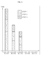
- the graph shown in FIG. 3 illustrates the total cumulative operation time of each of the auxiliary motors of FIG. 2 .
- the cumulative operation time of all ⁇ step 1> to ⁇ step 3> shows a significant difference depending on operation priorities predetermined for each of the auxiliary motors because the operation time of auxiliary motors withpriorities in each step is longer.
- the significant difference in such cumulative operation time contributes to concentrating mechanical stress just on some auxiliary motors to result in inefficient system operation, for example, failure.
- the present disclosure provides a method for controlling multiple motors to control a plurality of motors connected to a single inverter more stably and efficiently.
- a method for controlling multiple motors applicable to a multi-motor control system for controlling a plurality of motors through a single inverter includes: priority calculating process to calculate operation priorities of each of the plurality of motors through the use of cumulative operation time information for each of the plurality of motors; and motor controlling process to operate or stop the plurality of motors based on the priorities, which are calculated through the priority calculating process.
- the motor controlling process includes: motor operating process to operate the motor having the highest operation priority from the priorities, which are calculated through the priority calculating process, when additional operation of the motors is requested; and motor stopping process to stop operation of the motor having the lowest operation priority from the priorities, which are calculated through the priority calculating process, when stopping at least one of the motors in operation is requested.
- the operation priorities of each of the plurality of motors which are calculated through the priority calculating process, are set to be in inverse proportion to total cumulative operation time of the each motor.
- the operation priorities of each of the plurality of motors are calculated by the addition of weight information having total cumulative ON/OFF count information or recent operation time information relative to total cumulative operation time information of the each motor.
- the method further includes: when the difference between the total cumulative operation time of one motor with the longest total cumulative operation time among the motors in operation and the total cumulative operation time of the other motor with the shortest cumulative operation time among the motors which is not in operation is greater than a given range of limit, motor changing process to change operation of motors from the one motor to the other motor.
- auxiliary motors of which the total cumulative operation time is relatively shorter are always operated first to control a plurality of auxiliary motors connected to a single inverter. By doing this, since the operation time between entire auxiliary motors are balanced, it is thus possible to control multiple motors stably and efficiently.
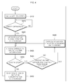
- FIG. 4 is a flow chart for illustrating a method for controlling multiple motors in accordance with an embodiment of the present disclosure.
- the method for controlling multiple motors in accordance with the embodiment of the present disclosure corresponds with a technology applicable to the system for controlling multiple motors described above and shown in FIG. 1 .
- the system for controlling multiple motors includes an inverter 110, a main motor 120 connected directly to the inverter 110, and a plurality of auxiliary motors 130 connected selectively to the inverter 110 through each relay 140.
- the system for controlling multiple motors shown in FIG. 1 operates one of the plurality of auxiliary motors 130 additionally when output thereof is not enough just by the main motor 120.
- the method in accordance with the present disclosure may be usefully applicable to a system for controlling motors which includes the main motor 120 and the plurality of auxiliary motors 130 and drives the plurality of auxiliary motors 130 connected through the relay 140 when the feedback pressure in the pipeline P is not be normally kept just by driving the main motor 120.
- the present disclosure is not limited and applicable just to this configuration.
- auxiliary motors that may be driven additionally together with the main motor may be called "motors”.
- the method for controlling multiple motors in accordance with an embodiment of the present disclosure includes process S410 for calculating priorities, process S420 for operating motors and process S430 for stopping motor operation. That is, the process S410 for calculating priorities is a process of using total cumulative operation time information for each motor and calculating operation priorities.
- process S410 for calculating priorities of the method for controlling multiple motors is to calculate operation priorities of each of the plurality of motors, on the basis of the total cumulative operation time information of the plurality of motors.
- a control unit of the system calculates and manages total cumulative operation time information for each of the plurality of motors, and determines operation priorities of each of the plurality of motors to be in inverse proportion to the calculated cumulative operation time of each motor. That is, in accordance with an embodiment, the operation priorities of each motor are in inverse proportion to the cumulative operation time of each motor.
- process S420 for operating motors is carried out to operate at least one of the plurality of motors in order of higher operation priorities.
- any motor with a higher operation priority that is, shorter total cumulative operation time among the plurality of motors, is first operated.
- process S440 for changing operation from the first motor in operation to the second motor which is not in operation may be carried out additionally.
- process S440 for changing operation of motors may be automatically carried out for stopping the first motor in operation and operating the second motor which is not in operation instead.
- the method for controlling multiple motors in accordance with an embodiment of the present disclosure includes process S450 for updating the cumulative operation time information to identify operation time information of each motor in real time.
- simultaneous operation of the motors of changed operation may be carried out for a given time period in order to avoid a gap that occurs when no motor operates.
- a gap may occur when no motor operates for a given time period until output from the other motor reaches a normal level.
- the first motor may be stopped after the output of the second motor reaches the normal level.
- simultaneous operation may be carried out for a given time period among the motors of changed operation.
- the configuration is made to allow operators to change the time predetermined for simultaneous operation of the motors.
- the present disclosure is not limited to the configuration.
- both the first motor and the second motor are simultaneously operated for a given time period to enable the output of the second motor to reach a normal level. After that, when the output of the second motor reaches the normal level, the first motor is stopped and the second motor is just operated.
- total cumulative operation time information about the motors in operation may be updated and saved in real time at process S450 in this case.
- calculating the operation priorities of each of the plurality of motors may be further based on at least one of total cumulative ON/OFF count information and recent operation time information of the plurality of motors in addition to the total cumulative operation time information of each motor.
- operation priorities of each motor are calculated by using just the total cumulative operation time of each motor.
- weights are calculated by using total cumulative ON/OFF count information or recent operation time information of each motor to apply them to calculating operation priorities of the motors.
- the recent operation time information refers to the operation time information about a concerned motor which has been operated for hours to days before the current time.
- the time range in the recent operation time information may be configured to be predetermined or changed by users including operators.
- the recent operation time information may mean operation time information about the concerned motor of concentrated operation, carried out commonly for 24 to 48 hours before the current time.
- the information applicable to calculating weights in accordance with the embodiment of the present disclosure is not limited just to total cumulative ON/OFF count information or recent concentrated operation time information, and it will be apparent to those skilled in the art that operators may determine weight configuration factors and their ratios in consideration of actually implemented system environment and the like.
- any common techniques may be applied to addressing the case that the same priorities are calculated for two or more motors.
- the total cumulative ON/OFF count information or the recent cumulative concentrated operation time information described above may be applied to addressing the issue of same priorities.
- the same priorities may be resolved by means of the technique for putting more weights on the total cumulative operation time information.
- FIG. 5 is a graph for illustrating the state of motor operation in accordance with each embodiment of the present disclosure for the system shown in FIG. 1 .
- the auxiliary motor 4 on the assumption that the auxiliary motor 1, the auxiliary motor 2 and the auxiliary motor 3 are operated additionally in sequence in ⁇ step 1>, the auxiliary motor 4, the auxiliary motor 5 and the auxiliary motor 3 are operated additionally, in ⁇ step 2>, in sequence in consideration of the priorities calculated by using the cumulative operation time information of ⁇ step 1>.
- the auxiliary motor 5, the auxiliary motor 2 and the auxiliary motor 4 are operated additionally in sequence in ⁇ step 3>in consideration of the priorities determined by using the motor operation information (total cumulative operation time information, etc.) in ⁇ step 1> and ⁇ step 2>.
- FIG. 1 is a configuration with one main motor 120 and five auxiliary motors 130 and five relays 140 connected to each auxiliary motor in the pipeline P, but it should be noted that this is an exemplary configuration of the system for describing embodiments of the present disclosure, and the present disclosure is not limited just to systems with such a configuration.
- FIG. 6 is a graph showing total cumulative operation time of each of auxiliary motors of FIG. 5 .
- auxiliary motors represent somewhat uniform total cumulative operation time.
- the auxiliary motor 3 with the shortest total cumulative operation time currently is given the highest priority. Therefore, it is seen that if operation of auxiliary motors is requested in the next step, additional operation is carried out in order of the auxiliary motor 3, the auxiliary motor 2 and the auxiliary motor 4.
- calculating priorities applied to the method for controlling multiple motors in accordance with each embodiment of the present disclosure is not determined just in consideration of the total cumulative operation time information of motors. As described above, different weights may be added, with various configuration factors and ratios determined by operators in consideration of actually implemented environment of the system provided with motors.
- the system is configured to identify priorities in detail among motors with the same operation priorities through the technique for giving weights to the total cumulative ON/OFF count information, recent concentrated operation time information or total cumulative operation time information of the motors.
- the operation priorities of each of the plurality of auxiliary motors are calculated on the basis of the order of shorter total cumulative operation time, the order of smaller total ON/OFF switch counts and the order of shorter recent operation time.
- at least one of the plurality of auxiliary motors is driven in sequence in order of higher operation priorities.
- at least one of the auxiliary motors in operation is stopped in sequence in order of lower operation priorities.
- the similar level of operation times of each of auxiliary motors may be implemented each other.
- controlling the system by using the plurality of auxiliary motors may be further facilitated and managing the plurality of auxiliary motors may be further facilitated.
- auxiliary motors with relatively higher priorities calculated by using total cumulative operation time information are first operated to control a plurality of auxiliary motors connected selectively to an inverter through relays or switches unlike the main motor connected directly to the inverter.
- operation time may be kept uniform among entire auxiliary motors. Therefore, repeated failure of conventional motors that happens due to load concentrated just on some motors may be resolved, and a multi-motor control system may be further controlled stably and efficiently.
Landscapes
- Engineering & Computer Science (AREA)
- Power Engineering (AREA)
- Control Of Multiple Motors (AREA)
- Inverter Devices (AREA)
Applications Claiming Priority (1)
| Application Number | Priority Date | Filing Date | Title |
|---|---|---|---|
| KR1020150077584A KR20160148729A (ko) | 2015-06-01 | 2015-06-01 | 복수 전동기의 제어 방법 |
Publications (2)
| Publication Number | Publication Date |
|---|---|
| EP3101802A2 true EP3101802A2 (de) | 2016-12-07 |
| EP3101802A3 EP3101802A3 (de) | 2016-12-21 |
Family
ID=56087117
Family Applications (1)
| Application Number | Title | Priority Date | Filing Date |
|---|---|---|---|
| EP16170067.9A Withdrawn EP3101802A3 (de) | 2015-06-01 | 2016-05-18 | Verfahren zur steuerung mehrerer motoren |
Country Status (5)
| Country | Link |
|---|---|
| US (1) | US20160352261A1 (de) |
| EP (1) | EP3101802A3 (de) |
| JP (1) | JP2016226280A (de) |
| KR (1) | KR20160148729A (de) |
| CN (1) | CN106208825A (de) |
Families Citing this family (5)
| Publication number | Priority date | Publication date | Assignee | Title |
|---|---|---|---|---|
| CN108643283A (zh) * | 2018-05-09 | 2018-10-12 | 合肥亿福自动化科技有限公司 | 一种冗余水泵均衡不停机系统 |
| CN108730170A (zh) * | 2018-05-25 | 2018-11-02 | 蚌埠凯盛工程技术有限公司 | 一种多电机优化控制系统及其优化控制方法 |
| JPWO2020202469A1 (ja) * | 2019-04-02 | 2021-10-14 | 三菱電機株式会社 | 電動機制御装置 |
| JP7329184B2 (ja) * | 2019-07-25 | 2023-08-18 | 株式会社リコー | シート搬送装置及び画像形成装置 |
| JP2021024440A (ja) * | 2019-08-05 | 2021-02-22 | 株式会社デンソーテン | 制御装置および制御方法 |
Citations (1)
| Publication number | Priority date | Publication date | Assignee | Title |
|---|---|---|---|---|
| JPH09269802A (ja) * | 1996-04-02 | 1997-10-14 | Hitachi Building Syst Co Ltd | 給水用ポンプの運転制御装置 |
Family Cites Families (15)
| Publication number | Priority date | Publication date | Assignee | Title |
|---|---|---|---|---|
| US3948060A (en) * | 1972-05-24 | 1976-04-06 | Andre Jean Gaspard | Air conditioning system particularly for producing refrigerated air |
| US3757179A (en) * | 1972-10-24 | 1973-09-04 | Gen Electric | Voltage control of an ac drive system during motor starting |
| US3881140A (en) * | 1974-03-01 | 1975-04-29 | American Seating Co | System for expanding and retracting telescoping seating row sections |
| CH611089A5 (de) * | 1976-11-22 | 1979-05-15 | Carpano & Pons | |
| US4686434A (en) * | 1985-03-14 | 1987-08-11 | Mitsubishi Denki Kabushiki Kaisha | Electric vehicle monitoring system |
| JPS63107495A (ja) * | 1986-10-22 | 1988-05-12 | Hitachi Ltd | 電動機の運転制御装置 |
| DE58903262D1 (de) * | 1988-07-06 | 1993-02-25 | Rieter Ag Maschf | Synchronisierbare antriebssysteme. |
| JPH05168293A (ja) * | 1991-12-18 | 1993-07-02 | Toshiba Corp | 電動機運転システム |
| JPH1172087A (ja) * | 1997-07-03 | 1999-03-16 | Kensetsusho Kanto Chiho Kensetsu Kyokucho | モータ駆動による回転機械の運転装置およびその運転制御方法 |
| JP4595406B2 (ja) * | 2004-07-06 | 2010-12-08 | 富士電機システムズ株式会社 | 複数台モータ駆動装置 |
| KR20060033358A (ko) * | 2004-10-15 | 2006-04-19 | 삼성전자주식회사 | 다실형 공기 조화기의 압축기 제어장치 및 방법 |
| FI121130B (fi) * | 2008-02-29 | 2010-07-15 | Vacon Oyj | Sähkömoottorin kytkeminen syöttöverkkoon |
| JP5884154B2 (ja) * | 2011-09-29 | 2016-03-15 | Jfeスチール株式会社 | 被制御機器の運転制御方法 |
| KR20140049107A (ko) * | 2012-10-12 | 2014-04-25 | 대우조선해양 주식회사 | 선박의 해수펌프 제어시스템 및 그 방법 |
| JP5752296B2 (ja) * | 2013-06-27 | 2015-07-22 | ファナック株式会社 | 振動モータを備えた可搬式操作盤 |
-
2015
- 2015-06-01 KR KR1020150077584A patent/KR20160148729A/ko not_active Ceased
-
2016
- 2016-05-18 EP EP16170067.9A patent/EP3101802A3/de not_active Withdrawn
- 2016-05-27 US US15/167,143 patent/US20160352261A1/en not_active Abandoned
- 2016-05-31 JP JP2016108038A patent/JP2016226280A/ja active Pending
- 2016-06-01 CN CN201610382464.2A patent/CN106208825A/zh active Pending
Patent Citations (1)
| Publication number | Priority date | Publication date | Assignee | Title |
|---|---|---|---|---|
| JPH09269802A (ja) * | 1996-04-02 | 1997-10-14 | Hitachi Building Syst Co Ltd | 給水用ポンプの運転制御装置 |
Also Published As
| Publication number | Publication date |
|---|---|
| JP2016226280A (ja) | 2016-12-28 |
| EP3101802A3 (de) | 2016-12-21 |
| CN106208825A (zh) | 2016-12-07 |
| US20160352261A1 (en) | 2016-12-01 |
| KR20160148729A (ko) | 2016-12-27 |
Similar Documents
| Publication | Publication Date | Title |
|---|---|---|
| EP3101802A2 (de) | Verfahren zur steuerung mehrerer motoren | |
| US9939804B2 (en) | Numerical control device and numerical control method | |
| EP2846320B1 (de) | Einzelzyklusoffsetabgleich für Verkehrssignalsteuerungen | |
| EP2942679A3 (de) | Systeme und Verfahren zur Steuerung und Bedienung einer parallelen Motorsteuerungsarchitektur | |
| EP4535644A3 (de) | Sensorlose motorsteuerung für ein elektrowerkzeug | |
| US20150015173A1 (en) | Motor control device | |
| CN101261501A (zh) | 受控制的机器的运行方法 | |
| WO2011049568A1 (en) | Stepper motor controller | |
| JP6657060B2 (ja) | 複数のインバータの制御装置およびこれを適用したインバータシステム | |
| US9780699B2 (en) | Motor protection relay and method for starting motor of motor protection relay | |
| JP2016001437A (ja) | 制御軸切換えを行う数値制御装置 | |
| EP3564817B1 (de) | Steuerungssystem für mobilen körper und steuerungsverfahren für mobilen körper | |
| JP5220298B2 (ja) | 電圧型インバータ制御装置 | |
| JP6632710B2 (ja) | 機械制御部のためのフィルタ切り換え方法、プログラム、機械の制御ユニットおよび機械 | |
| CN115333426B (zh) | 电机的控制模式切换方法、装置、伺服驱动设备和介质 | |
| US12123360B2 (en) | Pooled architecture for controlling electromechanical actuators | |
| JP2000020118A (ja) | 数値制御装置及びその指令位置算出方法 | |
| US9124198B2 (en) | Multiplexed motor controller | |
| CN118107633A (zh) | 车辆的控制方法、存储介质和电子设备 | |
| US7627403B2 (en) | Bias correcting phase compensating rate limiter | |
| US9798296B2 (en) | Method for controlling inverter | |
| KR102492399B1 (ko) | 감시제어장치 | |
| JP2023148366A (ja) | モータ制御装置、モータシステム、モータ制御方法およびモータ制御プログラム | |
| CN108136915A (zh) | 一种运行永励同步电机,尤其转向系统中的伺服马达的方法 | |
| CN112443901A (zh) | 制冷循环系统、用于控制制冷循环系统的方法以及用于制冷循环系统的控制器 |
Legal Events
| Date | Code | Title | Description |
|---|---|---|---|
| PUAI | Public reference made under article 153(3) epc to a published international application that has entered the european phase |
Free format text: ORIGINAL CODE: 0009012 |
|
| STAA | Information on the status of an ep patent application or granted ep patent |
Free format text: STATUS: THE APPLICATION HAS BEEN PUBLISHED |
|
| PUAL | Search report despatched |
Free format text: ORIGINAL CODE: 0009013 |
|
| AK | Designated contracting states |
Kind code of ref document: A2 Designated state(s): AL AT BE BG CH CY CZ DE DK EE ES FI FR GB GR HR HU IE IS IT LI LT LU LV MC MK MT NL NO PL PT RO RS SE SI SK SM TR |
|
| AX | Request for extension of the european patent |
Extension state: BA ME |
|
| AK | Designated contracting states |
Kind code of ref document: A3 Designated state(s): AL AT BE BG CH CY CZ DE DK EE ES FI FR GB GR HR HU IE IS IT LI LT LU LV MC MK MT NL NO PL PT RO RS SE SI SK SM TR |
|
| AX | Request for extension of the european patent |
Extension state: BA ME |
|
| RIC1 | Information provided on ipc code assigned before grant |
Ipc: H02P 5/46 20060101AFI20161116BHEP Ipc: H02P 29/02 20060101ALI20161116BHEP |
|
| STAA | Information on the status of an ep patent application or granted ep patent |
Free format text: STATUS: REQUEST FOR EXAMINATION WAS MADE |
|
| 17P | Request for examination filed |
Effective date: 20170619 |
|
| RBV | Designated contracting states (corrected) |
Designated state(s): AL AT BE BG CH CY CZ DE DK EE ES FI FR GB GR HR HU IE IS IT LI LT LU LV MC MK MT NL NO PL PT RO RS SE SI SK SM TR |
|
| STAA | Information on the status of an ep patent application or granted ep patent |
Free format text: STATUS: EXAMINATION IS IN PROGRESS |
|
| 17Q | First examination report despatched |
Effective date: 20200107 |
|
| STAA | Information on the status of an ep patent application or granted ep patent |
Free format text: STATUS: THE APPLICATION HAS BEEN WITHDRAWN |
|
| 18W | Application withdrawn |
Effective date: 20200323 |