EP3101363A1 - Absperrklappe für den einsatz in einem kanal einer raumlufttechnischen anlage oder einer maschinellen entrauchungsanlage - Google Patents
Absperrklappe für den einsatz in einem kanal einer raumlufttechnischen anlage oder einer maschinellen entrauchungsanlage Download PDFInfo
- Publication number
- EP3101363A1 EP3101363A1 EP15170058.0A EP15170058A EP3101363A1 EP 3101363 A1 EP3101363 A1 EP 3101363A1 EP 15170058 A EP15170058 A EP 15170058A EP 3101363 A1 EP3101363 A1 EP 3101363A1
- Authority
- EP
- European Patent Office
- Prior art keywords
- seal
- flap
- butterfly valve
- housing
- valve according
- Prior art date
- Legal status (The legal status is an assumption and is not a legal conclusion. Google has not performed a legal analysis and makes no representation as to the accuracy of the status listed.)
- Granted
Links
Images




Classifications
-
- F—MECHANICAL ENGINEERING; LIGHTING; HEATING; WEAPONS; BLASTING
- F24—HEATING; RANGES; VENTILATING
- F24F—AIR-CONDITIONING; AIR-HUMIDIFICATION; VENTILATION; USE OF AIR CURRENTS FOR SCREENING
- F24F13/00—Details common to, or for air-conditioning, air-humidification, ventilation or use of air currents for screening
- F24F13/08—Air-flow control members, e.g. louvres, grilles, flaps or guide plates
- F24F13/10—Air-flow control members, e.g. louvres, grilles, flaps or guide plates movable, e.g. dampers
- F24F13/14—Air-flow control members, e.g. louvres, grilles, flaps or guide plates movable, e.g. dampers built up of tilting members, e.g. louvre
- F24F13/1406—Air-flow control members, e.g. louvres, grilles, flaps or guide plates movable, e.g. dampers built up of tilting members, e.g. louvre characterised by sealing means
-
- A—HUMAN NECESSITIES
- A62—LIFE-SAVING; FIRE-FIGHTING
- A62C—FIRE-FIGHTING
- A62C2/00—Fire prevention or containment
- A62C2/06—Physical fire-barriers
- A62C2/12—Hinged dampers
-
- C—CHEMISTRY; METALLURGY
- C09—DYES; PAINTS; POLISHES; NATURAL RESINS; ADHESIVES; COMPOSITIONS NOT OTHERWISE PROVIDED FOR; APPLICATIONS OF MATERIALS NOT OTHERWISE PROVIDED FOR
- C09K—MATERIALS FOR MISCELLANEOUS APPLICATIONS, NOT PROVIDED FOR ELSEWHERE
- C09K3/00—Materials not provided for elsewhere
- C09K3/10—Materials in mouldable or extrudable form for sealing or packing joints or covers
- C09K3/1006—Materials in mouldable or extrudable form for sealing or packing joints or covers characterised by the chemical nature of one of its constituents
-
- C—CHEMISTRY; METALLURGY
- C09—DYES; PAINTS; POLISHES; NATURAL RESINS; ADHESIVES; COMPOSITIONS NOT OTHERWISE PROVIDED FOR; APPLICATIONS OF MATERIALS NOT OTHERWISE PROVIDED FOR
- C09K—MATERIALS FOR MISCELLANEOUS APPLICATIONS, NOT PROVIDED FOR ELSEWHERE
- C09K3/00—Materials not provided for elsewhere
- C09K3/10—Materials in mouldable or extrudable form for sealing or packing joints or covers
- C09K2003/1034—Materials or components characterised by specific properties
- C09K2003/1037—Intumescent materials
-
- E—FIXED CONSTRUCTIONS
- E06—DOORS, WINDOWS, SHUTTERS, OR ROLLER BLINDS IN GENERAL; LADDERS
- E06B—FIXED OR MOVABLE CLOSURES FOR OPENINGS IN BUILDINGS, VEHICLES, FENCES OR LIKE ENCLOSURES IN GENERAL, e.g. DOORS, WINDOWS, BLINDS, GATES
- E06B5/00—Doors, windows, or like closures for special purposes; Border constructions therefor
- E06B5/10—Doors, windows, or like closures for special purposes; Border constructions therefor for protection against air-raid or other war-like action; for other protective purposes
- E06B5/16—Fireproof doors or similar closures; Adaptations of fixed constructions therefor
- E06B5/164—Sealing arrangements between the door or window and its frame, e.g. intumescent seals specially adapted therefor
-
- F—MECHANICAL ENGINEERING; LIGHTING; HEATING; WEAPONS; BLASTING
- F24—HEATING; RANGES; VENTILATING
- F24F—AIR-CONDITIONING; AIR-HUMIDIFICATION; VENTILATION; USE OF AIR CURRENTS FOR SCREENING
- F24F11/00—Control or safety arrangements
- F24F11/30—Control or safety arrangements for purposes related to the operation of the system, e.g. for safety or monitoring
- F24F11/32—Responding to malfunctions or emergencies
- F24F11/33—Responding to malfunctions or emergencies to fire, excessive heat or smoke
- F24F11/35—Responding to malfunctions or emergencies to fire, excessive heat or smoke by closing air passages
-
- F—MECHANICAL ENGINEERING; LIGHTING; HEATING; WEAPONS; BLASTING
- F24—HEATING; RANGES; VENTILATING
- F24F—AIR-CONDITIONING; AIR-HUMIDIFICATION; VENTILATION; USE OF AIR CURRENTS FOR SCREENING
- F24F2221/00—Details or features not otherwise provided for
- F24F2221/30—Details or features not otherwise provided for comprising fireproof material
Definitions
- the invention relates to a butterfly valve for use in a duct of a ventilation system or a mechanical smoke extraction system, the butterfly valve having a, in particular a quadrangular cross-section, housing having a housing wall and one in the housing to one, in particular centrally relative to the housing cross-section arranged, Swivel axis between an open position and a closed position pivotally mounted flap with a circumferential, interrupted only by the pivot axis, comprises, wherein at least one passage for the pivot axis is provided in the housing, wherein on the outside of the edge a seal is provided and wherein the flap under Forming a remaining in the closed position of the flap gap between the edge of the flap and the inside of the housing is smaller than the cross-sectional area of the housing is formed and the seal in the closed position of the flap, the gap a bêtt.
- Butterfly valves should close the flow cross-section in their closed position and thus prevent a flow of a medium.
- a stop may be provided in the housing, against which the flap rests in its closed position.
- Butterfly valves especially if they are designed as fire or smoke control, represent a safety-relevant component, so that, for example, in the case of fire, the flow cross-section must be sufficiently sealed. Known seals do not provide a sufficient seal in every situation.
- the object of the invention is to avoid the aforementioned disadvantages and to provide a butterfly valve, which ensures a secure seal of the flow cross-section in the closed position of the flap.
- the seal comprises a cold seal and a heat seal expanding heat seal, wherein at least the cold seal protrudes from the edge of the flap and wherein on the edge at least on one side of the cold seal, preferably on both sides of the cold seal , one each - in particular directly adjacent to the cold seal, ie with the cold seal in contact - hot seal is arranged.
- the seal may for example be glued or screwed onto the edge of the flap.
- a groove-shaped recess is provided in the edge, in which the seal is fixed accordingly.
- the butterfly valve according to the invention is characterized in that only one seal on the edge of the flap is required and - if, for example, a stop for defining the closed position is provided on the inside of the housing - no stop seal is required. This leads to a reduction of the components.
- the seal according to the invention thus ensures both a cold seal through the cold seal and, in the case of a temperature development, a hot seal through the hot seal.
- the cold seal may consist, for example, of a non-combustible mineral fiber-containing material, in particular a mineral fiber foam.
- the heat-expanding, intumescent hot seal can be, for example, powdered graphite, a polymer compound and Synthetic resin include.
- a polymer compound is a polymer that is mixed with certain chemical components that are released when melting under the influence of temperature and then enter into a chemical reaction with the graphite. In this chemical reaction, long molecular chains are formed, which produce the desired volume change.
- the task of the resin is to prevent dripping of the mixture in case of fire.
- a foaming of the material should be carried out at a temperature of about 160 ° C.
- the flap may for example consist of a cement-bound calcium-silicate material, such as a fire protection board.
- the hot seal may be strip-shaped. If it comes to a temperature development, the material foams accordingly.
- the cold seal can be designed as a hollow profile seal, in particular as a hollow profile seal having a round or semicircular cross section. Of course, other cross-sectional shapes are conceivable.
- thermoplastic elastomer TPE
- the cold seal can be in contact with the inside of the housing at least in its closed position in the closed position Area have at least one, at least over a portion of the cold seal, preferably over the entire length of the cold seal, extending, in particular made of polypropylene (PP), existing sliding strip.
- PP polypropylene
- the seal for attachment to the flap on its side facing the flap at least over a partial area the seal, preferably over the entire length of the seal, extending, in particular made of polypropylene (PP), have web, which is insertable into a groove provided in the edge of the flap.
- PP polypropylene
- the web may have at least one laterally projecting, in particular made of a thermoplastic elastomer (TPE), locking lug.
- TPE thermoplastic elastomer
- corresponding latching lugs are provided on both sides of the web, so that the web has a kind of pine profile.
- the seal may be formed as an extruded component. In such a configuration is so far a coextruded seal consisting of a cold seal and at least one hot seal.
- the seal may be formed in one piece.
- each hot seal is firmly connected to the cold seal so that the seal as a whole can be attached to the flap and removed.
- the one-piece design does not exclude that the cold seal and the hot seal (s) consist of different materials.
- the butterfly valve may be designed as smoke control.
- Smoke dampers serve to keep areas in a building, for example an escape area, smoke-free.
- the area of application of a smoke extraction damper is at a temperature which is between the ambient temperature of the respective smoke-free area (cold smoke extraction) and a temperature of up to 1000 ° C or more (hot smoke extraction).
- smoke control valves must firstly a cold seal and the other ensure a warm seal. Due to the possibly high temperatures usually consist of the housing, the flap, the stops and arranged on the outside of the housing motor encapsulation of the drive means of calcium silicate.
- Smoke dampers are usually triggered by a smoke detector. Of course, other tripping devices, such.
- a remote triggering device As a manual triggering device, a remote triggering device or the like, conceivable.
- the energy to open and close must be permanently applied to the flap.
- Smoke dampers are designed so that even after the release, ie after pivoting from the open position into the closed position, a subsequent opening, ie pivoting into the open position, is ensured. Of course, this also applies to the reverse case.
- the butterfly valve can also be designed as a fire damper.
- Fire dampers usually have a metal housing in which a made of calcium silicate flap is pivotally mounted.
- a fire damper for example, be manually operable.
- the flap is displaceable against a restoring force from its closed position into its open position and can be fixed in its open position by a fixing and releasing device.
- For pivoting the flap from its closed position against the restoring force in the open position, ie for tensioning the spring, is usually a preferably arranged on the outside of the housing actuating element, such.
- B. an actuating handle provided.
- the flap is fixed by means of a fixing device against a restoring force in its open position.
- the flap in case of fire, ie when the temperature exceeds a value of about 72 ° C, the flap is from the fixed position after triggering a triggering device, such as a fusible link, by the restoring force, which is provided by the spring from its open position to its closed position pivoted.
- a triggering device such as a fusible link
- the intumescent material ie the material that expands or foams when the heat is warm, puffs up.
- the intumescent material now completely fills a possibly existing gap between the edge of the flap and the inside of the housing, so that the gap is sealed.
- the flap can now no longer be opened and must later be replaced.
- a triggering devices other embodiments, such as an electric fusible link, conceivable.
- butterfly valve can also be designed as a combined fire protection and smoke control.
- a drive device acts directly or indirectly on the flap.
- the flap can be moved by motor to the desired position.
- the drive device is designed for example as a spring return motor.
- a spring is tensioned in the spring return motor.
- a thermoelectric triggering device which may be, for example, an electric soldering, causes a power interruption.
- the spring return motor can no longer counteract the restoring force generated by the tensioned spring, so that the flap is closed by the restoring force applied by the spring.
- a smoke control damper comprises a motor drive device
- an applied voltage is required both for pivoting the flap from the open position to its closed position and for pivoting the flap from the closed position to its open position.
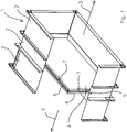
- Fig. 1 shows a butterfly valve for use in a duct of a ventilation system, wherein the butterfly valve has a housing 1 with a quadrangular cross-section.
- the housing 1 has a housing wall 2.
- the butterfly valve is seen in the flow direction 3 is formed in three parts, ie it consists of three segments, adjacent segments are connected to each other via a flange.
- the butterfly valve seen in the flow direction 3 has only one segment.
- Each housing wall 2 of a segment consists in the illustrated embodiment of four housing wall areas.
- a flap 4 is provided in the housing, which is pivotally mounted about an axis of rotation relative to the cross section of the housing 1 arranged pivot axis 5 between an open position and a closed position.
- a passage for the pivot axis 5 is provided on each side.
- the flap 4 has a peripheral edge 6. On the outside of the edge 6 of the flap 4, a seal 7 is provided, which only by the pivot axis 5 is interrupted. In the closed position of the flap 4 remains a gap between the edge 6 of the flap 4 and the inside of the housing 1, since the flap 4 is smaller than the cross-sectional area of the housing 1 is formed.
- the seal 7 consists of a cold seal 8 and two heat seals expanding heat seals 9.
- the cold seal 8 is opposite the edge 6 of the flap 4 clearly out, so that in the closed position of the flap 4, the gap is sealed.
- the two hot seals 9 are each formed strip-shaped.
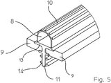
- the cold seal 8 is designed as a hollow profile seal, wherein in the Fig. 2 to 4 the hollow profile seal a round and in the Fig. 5 to 7 has a semicircular cross-section.
- the cold seal 8 may consist of a thermoplastic elastomer.
- Fig. 5 to 7 has the cold seal 8 on its upper side in the in the closed position with the inside of the housing 1 in contact area several over the entire length of the cold seal 8 extending, in particular of polypropylene (PP) existing, sliding strip 10.
- PP polypropylene
- the seal 7 for attachment to the flap 4 on its side facing the flap 4 a over the entire length of the seal 7 extending web 11 which is insertable into a provided in the edge 6 of the flap 4 groove 12.
- a mounting portion 13 is provided on the web 11, to which the cold seal 8 is attached.
- the mounting area 13 rests on the upper side on the respectively adjacent hot seal 9.
- the web 11 has in the illustrated embodiments on both sides in each case two continuous locking lugs 14, which consist for example of a thermoplastic elastomer on.
- the bridge 11 is a kind of fir profile.
- the locking lugs 14 prevent inadvertent release of the inserted into the groove 12 web 11th
- a recess 15 is provided in the edge 6, whose width is slightly larger than the width of the seal 7.
- the height of the recess 15 is selected so that the thickness of the two heat seals 9 is slightly lower, so that only the cold seal 8 protrudes from the edge 6.
Landscapes
- Chemical & Material Sciences (AREA)
- Engineering & Computer Science (AREA)
- Combustion & Propulsion (AREA)
- Mechanical Engineering (AREA)
- General Engineering & Computer Science (AREA)
- Materials Engineering (AREA)
- Organic Chemistry (AREA)
- Health & Medical Sciences (AREA)
- Public Health (AREA)
- Business, Economics & Management (AREA)
- Emergency Management (AREA)
- Lift Valve (AREA)
- Air-Flow Control Members (AREA)
Abstract
Description
- Die Erfindung betrifft eine Absperrklappe für den Einsatz in einem Kanal einer raumlufttechnischen Anlage oder einer maschinellen Entrauchungsanlage, wobei die Absperrklappe ein, insbesondere einen viereckigen Querschnitt aufweisendes, Gehäuse mit einer Gehäusewandung und eine in dem Gehäuse um eine, insbesondere mittig auf den Gehäusequerschnitt bezogen angeordnete, Schwenkachse zwischen einer Offenstellung und einer Schließstellung schwenkbar gelagerte Klappe mit einer umlaufenden, lediglich durch die Schwenkachse unterbrochenen Kante, umfasst, wobei in dem Gehäuse zumindest eine Durchführung für die Schwenkachse vorgesehen ist, wobei außenseitig auf der Kante eine Dichtung vorgesehen ist und wobei die Klappe unter Bildung eines in der Schließstellung der Klappe verbleibenden Spaltes zwischen der Kante der Klappe und der Innenseite des Gehäuses kleiner als die Querschnittsfläche des Gehäuses ausgebildet ist und die Dichtung in der Schließstellung der Klappe den Spalt abdichtet.
- Absperrklappen sollen in ihrer Schließstellung den Strömungsquerschnitt abschließen und so ein Strömen eines Mediums verhindern. Zur Definition der Schließstellung kann in dem Gehäuse ein Anschlag vorgesehen sein, an dem die Klappe in ihrer Schließstellung anliegt. Absperrklappen, insbesondere wenn sie als Brandschutz- oder Entrauchungsklappe ausgebildet sind, stellen eine sicherheitsrelevante Komponente dar, so dass beispielsweise im Falle eines Brandes der Strömungsquerschnitt hinreichend abgedichtet sein muss. Bekannte Dichtungen gewähren nicht in jeder Situation eine hinreichende Abdichtung.
- Aufgabe der Erfindung ist es, die vorgenannten Nachteile zu vermeiden und eine Absperrklappe anzugeben, die eine sichere Abdichtung des Strömungsquerschnittes in der Schließstellung der Klappe gewährleistet.
- Diese Aufgabe wird dadurch gelöst, dass die Dichtung eine Kaltdichtung und eine sich bei Wärmeeinwirkung ausdehnende Warmdichtung aufweist, wobei zumindest die Kaltdichtung gegenüber der Kante der Klappe hervorsteht und wobei auf der Kante zumindest auf einer der beiden Seiten der Kaltdichtung, vorzugsweise auf beiden Seiten der Kaltdichtung, jeweils eine - insbesondere unmittelbar an die Kaltdichtung angrenzende, d.h. mit der Kaltdichtung in Kontakt befindliche - Warmdichtung angeordnet ist. Im einfachsten Fall kann die Dichtung beispielsweise auf die Kante der Klappe aufgeklebt oder aufgeschraubt sein. Selbstverständlich ist es aber auch möglich, dass in der Kante eine nutenförmige Ausnehmung vorgesehen ist, in die die Dichtung entsprechend fixierbar ist.
- Die erfindungsgemäße Absperrklappe zeichnet sich dadurch aus, dass nur noch eine Dichtung auf der Kante der Klappe erforderlich ist und - sofern beispielsweise auf der Innenseite des Gehäuses ein Anschlag zur Definition der Schließstellung vorgesehen ist - keine Anschlagdichtung mehr erforderlich ist. Dies führt zu einer Reduzierung der Bauteile. Die erfindungsgemäße Dichtung gewährleistet insoweit sowohl eine Kaltabdichtung durch die Kaltdichtung als auch im Falle einer Temperaturentwicklung eine Warmabdichtung durch die Warmdichtung.
- Die Kaltdichtung kann beispielsweise aus einem nicht brennbaren mineralfaserhaltigen, insbesondere als Mineralfaserschaumstoff ausgebildeten, Material bestehen.
- Die durch Wärmeeinwirkung ausdehnende, intumeszierende Warmdichtung kann beispielsweise pulverisiertes Graphit, einen Polymer-Compound und Kunstharz umfassen. Ein Polymer-Compound stellt ein Polymer dar, welches mit bestimmten chemischen Bestandteilen versetzt ist, die beim Schmelzen unter Temperatureinfluss freigesetzt werden und dann mit dem Graphit eine chemische Reaktion eingehen. Bei dieser chemischen Reaktion bilden sich lange Molekülketten, die die gewünschte Volumenänderung hervorrufen. Die Aufgabe des Harzes ist es, ein Abtropfen der Mischung im Brandfall zu verhindern. Üblicherweise soll ein Aufschäumen des Materials bei einer Temperatur von etwa 160 °C erfolgen.
- Die Klappe kann beispielsweise aus einem zementgebundenen Kalzium-Silikat-Material, wie beispielsweise einer Brandschutzbauplatte, bestehen.
- Die Warmdichtung kann streifenförmig ausgebildet sein. Kommt es zu einer Temperaturentwicklung, schäumt das Material entsprechend auf.
- Die Kaltdichtung kann als Hohlprofildichtung, insbesondere als eine einen runden oder halbkreisförmigen Querschnitt aufweisende Hohlprofildichtung, ausgebildet sein. Selbstverständlich sind auch andere Querschnittsformen denkbar.
- Es bietet sich an, wenn die Kaltdichtung aus einem thermoplastischen Elastomer (TPE) besteht.
- Um die Reibung beim Verschwenken der Klappe, insbesondere beim Verschwenken aus ihrer Offenstellung in die Schließstellung, gegenüber der Innenseite des Gehäuses so gering wie möglich zu halten, kann die Kaltdichtung auf ihrer Oberseite zumindest in dem in der Schließstellung mit der Innenseite des Gehäuses in Kontakt befindlichen Bereich wenigstens einen, sich zumindest über einen Teilbereich der Kaltdichtung, vorzugsweise sich über die komplette Länge der Kaltdichtung, erstreckenden, insbesondere aus Polypropylen (PP) bestehenden, Gleitstreifen aufweisen.
- Es bietet sich an, wenn die Dichtung zur Befestigung an der Klappe auf ihrer der Klappe zugewandten Seite einen sich zumindest über einen Teilbereich der Dichtung, vorzugweise sich über die ganze Länge der Dichtung, erstreckenden, insbesondere aus Polypropylen (PP) bestehenden, Steg aufweisen, der in eine in der Kante der Klappe vorgesehene Nut einführbar ist. Dies erlaubt eine einfache Befestigung der Dichtung an der Klappe, da der Steg lediglich in die Nut eingeführt werden muss. Der Steg kann beispielsweise mit der Kaltdichtung der Dichtung verbunden sein.
- Es bietet sich an, wenn der Steg an seinem der Dichtung zugewandten Ende einen, insbesondere aus Polypropylen (PP) bestehenden, Montagebereich für die Befestigung weiterer Bestandteile der Dichtung, wie z.B. der Kaltdichtung, aufweist.
- Der Steg kann zumindest eine seitlich vorstehende, insbesondere aus einem thermoplastischen Elastomer (TPE) bestehende, Rastnase aufweisen. Vorzugsweise sind beidseits des Stegs entsprechende Rastnasen vorgesehen, so dass dem Steg eine Art Tannenprofil zukommt.
- Die Dichtung kann als extrudiertes Bauteil ausgebildet sein. Bei einer solchen Ausgestaltung handelt es sich insoweit um eine koextrudierte Dichtung bestehend aus einer Kaltdichtung und zumindest einer Warmdichtung.
- Die Dichtung kann einteilig ausgebildet sein. Bei einer solchen Ausgestaltung ist jede Warmdichtung fest mit der Kaltdichtung verbunden, so dass die Dichtung als Ganzes an der Klappe befestigt und entfernt werden kann. Die einteilige Ausgestaltung schließt nicht aus, dass die Kaltdichtung und die Warmdichtung(en) aus unterschiedlichen Materialien bestehen.
- Die Absperrklappe kann als Entrauchungsklappe ausgebildet sein. Entrauchungsklappen dienen dazu, Bereiche in einem Gebäude, beispielsweise einen Fluchtbereich, rauchfrei zu halten. Der Einsatzbereich einer Entrauchungsklappe ist bei einer Temperatur, die zwischen der Umgebungstemperatur des jeweils rauchfrei zu haltenden Bereichs (Kaltentrauchung) und einer Temperatur von bis zu 1000°C oder mehr (Heißentrauchung) liegt. Insoweit müssen Entrauchungsklappen zum einen eine Kaltabdichtung und zum anderen eine Warmabdichtung gewährleisten. Aufgrund der eventuell hohen Temperaturen bestehen üblicherweise das Gehäuse, die Klappe, die Anschläge und die auf der Außenseite des Gehäuses angeordnete Motorenkapselung der Antriebseinrichtung aus Calciumsilikat. Entrauchungsklappen werden üblicherweise durch einen Rauchmelder ausgelöst. Selbstverständlich sind auch andere Auslöseeinrichtungen, wie z. B. eine Handauslöseeinrichtung, eine Fernauslöseeinrichtung oder dergleichen, denkbar. Die Energie zum Öffnen und zum Schließen muss dauerhaft an der Klappe anliegen. Entrauchungsklappen sind so ausgelegt, dass auch nach dem Auslösen, d.h. nach einem Verschwenken aus der Offenstellung in die Schließstellung, ein anschließendes Öffnen, d.h. ein Verschwenken in die Offenstellung, gewährleistet ist. Selbstverständlich gilt dies auch für den umgekehrten Fall.
- Die Absperrklappe kann auch als Brandschutzklappe ausgebildet sein. Brandschutzklappen weisen üblicherweise ein Gehäuse aus Metall auf, in dem eine aus Calciumsilikat bestehende Klappe schwenkbar gelagert ist. Eine Brandschutzklappe kann beispielsweise manuell betätigbar sein. Die Klappe ist gegen eine Rückstellkraft aus ihrer Schließstellung in ihre Offenstellung verlagerbar und in ihrer Offenstellung durch eine Fixier- und Auslöseeinrichtung fixierbar. Für das Verschwenken der Klappe aus ihrer Schließstellung gegen die Rückstellkraft in die Offenstellung, d.h. zum Spannen der Feder, ist üblicherweise ein vorzugsweise auf der Außenseite des Gehäuses angeordnetes Betätigungselement, wie z. B. ein Betätigungsgriff, vorgesehen. Die Klappe wird mittels einer Fixiereinrichtung gegen eine Rückstellkraft in ihrer Offenstellung fixiert. Beispielsweise im Brandfall, d.h. wenn die Temperatur einen Wert von etwa 72°C übersteigt, wird die Klappe aus der fixierten Position nach Auslösen einer Auslöseeinrichtung, beispielsweise einem Schmelzlot, durch die Rückstellkraft, die von der Feder bereitgestellt wird, aus ihrer Offenstellung in ihre Schließstellung verschwenkt. Gleichzeitig bläht sich das intumeszierende Material, d.h. das die aus einem bei Wärme ausdehnende bzw. aufschäumende Material der Warmdichtung, auf. Das intumeszierende Material füllt nunmehr einen eventuell noch bestehenden Spalt zwischen der Kante der Klappe und der Innenseite des Gehäuses vollständig aus, so dass der Spalt abgedichtet ist. Die Klappe kann nunmehr nicht mehr geöffnet werden und muss später ausgetauscht werden. Selbstverständlich sind als Auslöseeinrichtungen auch andere Ausgestaltungen, wie beispielsweise ein elektrisches Schmelzlot, denkbar.
- Selbstverständlich kann die Absperrklappe auch als kombinierte Brandschutzund als Entrauchungsklappe ausgebildet sein.
- Es bietet sich an, wenn an der Klappe mittelbar oder unmittelbar eine Antriebseinrichtung angreift. Damit kann die Klappe motorisch in die gewünschte Stellung verfahren werden.
- Sofern es sich um eine Brandschutzklappe handelt, ist die Antriebseinrichtung beispielsweise als Federrücklaufmotor ausgebildet. Beim Öffnen der Klappe wird eine Feder in dem Federrücklaufmotor gespannt. Im Brandfall bewirkt eine thermoelektrische Auslöseeinrichtung, bei der es sich beispielsweise um ein elektrisches Schmelzlot handeln kann, eine Spannungsunterbrechung. Damit kann der Federrücklaufmotor der durch die gespannte Feder erzeugten Rückstellkraft nicht mehr entgegenwirken, so dass die Klappe durch die von der Feder aufgebrachte Rückstellkraft geschlossen wird.
- Soweit eine Entrauchungsklappe eine motorische Antriebseinrichtung umfasst, ist sowohl für ein Verschwenken der Klappe aus der Offenstellung in ihre Schließstellung als auch für ein Verschwenken der Klappe aus der Schließstellung in ihre Offenstellung eine anliegende Spannung erforderlich.
- Im Folgenden werden in den Zeichnungen dargestellte Ausführungsbeispiele der Erfindung erläutert. Es zeigen:
- Fig. 1
- eine schräge Draufsicht auf eine teilweise geschnitten dargestellte Absperrklappe mit rechteckigem Querschnitt,
- Fig. 2
- ein erstes Ausführungsbeispiel einer Dichtung,
- Fig. 3
- eine schräge Draufsicht auf den Bereich der Kante einer Klappe mit einer darin befestigten Dichtung gemäß
Fig. 2 , - Fig. 4
- einen Schnitt durch den Gegenstand nach
Fig. 3 , - Fig. 5
- ein zweites Ausführungsbeispiel einer Dichtung,
- Fig. 6
- eine schräge Draufsicht auf den Bereich der Kante einer Klappe mit einer darin befestigten Dichtung gemäß
Fig. 5 und - Fig. 7
- einen Schnitt durch den Gegenstand nach
Fig. 6 . - In allen Figuren werden für gleiche bzw. gleichartige Bauteile übereinstimmende Bezugszeichen verwendet.
-
Fig. 1 zeigt eine Absperrklappe für den Einsatz in einem Kanal einer raumlufttechnischen Anlage, wobei die Absperrklappe ein Gehäuse 1 mit einem viereckigen Querschnitt aufweist. Das Gehäuse 1 weist eine Gehäusewandung 2 auf. In dem dargestellten Ausführungsbeispiel ist die Absperrklappe in Strömungsrichtung 3 gesehen dreiteilig ausgebildet, d.h. sie besteht aus drei Segmenten, wobei benachbarte Segmente über eine Flanschverbindung miteinander verbunden sind. Selbstverständlich ist es auch möglich, dass die Absperrklappe in Strömungsrichtung 3 gesehen nur ein Segment aufweist. Jede Gehäusewandung 2 eines Segmentes besteht in dem dargestellten Ausführungsbeispiel aus vier Gehäusewandungsbereichen. - Ferner ist in dem Gehäuse eine Klappe 4 vorgesehen, die um eine bezogen auf den Querschnitt des Gehäuses 1 mittig angeordnete Schwenkachse 5 zwischen einer Offenstellung und einer Schließstellung schwenkbar gelagert ist. In dem Gehäuse 1 ist auf jeder Seite eine Durchführung für die Schwenkachse 5 vorgesehen.
- Die Klappe 4 weist eine umlaufende Kante 6 auf. Außenseitig auf der Kante 6 der Klappe 4 ist eine Dichtung 7 vorgesehen, die lediglich durch die Schwenkachse 5 unterbrochen ist. In der Schließstellung der Klappe 4 verbleibt ein Spalt zwischen der Kante 6 der Klappe 4 und der Innenseite des Gehäuses 1, da die Klappe 4 kleiner als die Querschnittsfläche des Gehäuses 1 ausgebildet ist.
- Wie den
Fig. 2 bis 7 zu entnehmen ist, besteht die Dichtung 7 aus einer Kaltdichtung 8 und zwei sich bei Wärmeeinwirkung ausdehnenden Warmdichtungen 9. Die Kaltdichtung 8 steht gegenüber der Kante 6 der Klappe 4 deutlich hervor, so dass hierdurch in der Schließstellung der Klappe 4 der Spalt abgedichtet wird. Die beiden Warmdichtungen 9 sind jeweils streifenförmig ausgebildet. - In allen Figuren ist die Kaltdichtung 8 als Hohlprofildichtung ausgebildet, wobei in den
Fig. 2 bis 4 die Hohlprofildichtung einen runden und in denFig. 5 bis 7 einen halbkreisförmigen Querschnitt aufweist. Die Kaltabdichtung 8 kann aus einem thermoplastischen Elastomer bestehen. - Bei dem Ausführungsbeispiel nach den
Fig. 5 bis 7 weist die Kaltdichtung 8 auf ihrer Oberseite in dem in der Schließstellung mit der Innenseite des Gehäuses 1 in Kontakt befindlichen Bereich mehrere sich über die komplette Länge der Kaltdichtung 8 erstreckende, insbesondere aus Polypropylen (PP) bestehende, Gleitstreifen 10 auf. - In den Ausführungsbeispielen weist die Dichtung 7 zur Befestigung an der Klappe 4 auf ihrer der Klappe 4 zugewandten Seite eine sich über die ganze Länge der Dichtung 7 erstreckenden Steg 11 auf, der in eine in der Kante 6 der Klappe 4 vorgesehene Nut 12 einführbar ist.
- Bei dem Ausführungsbeispiel nach den
Figuren 5 bis 7 ist zusätzlich an dem Steg 11 ein Montagebereich 13 vorgesehen, an dem die Kaltdichtung 8 befestigt ist. Der Montagebereich 13 liegt randseitig auf der jeweils angrenzenden Warmdichtung 9 oberseitig auf. - Der Steg 11 weist in den dargestellten Ausführungsbeispielen beidseitig jeweils zwei durchgehende Rastnasen 14, die beispielsweise aus einem thermoplastischen Elastomer bestehen, auf. Damit kommt dem Steg 11 eine Art Tannenprofil zu. Die Rastnasen 14 verhindern ein unbeabsichtigtes Lösen des in die Nut 12 eingesteckten Steges 11.
- In allen Ausführungsbeispielen ist in der Kante 6 eine Ausnehmung 15 vorgesehen, deren Breite etwas größer als die Breite der Dichtung 7 ist. Die Höhe der Ausnehmung 15 ist so gewählt, dass die Dicke der beiden Warmdichtungen 9 etwas geringer ist, so dass lediglich die Kaltdichtung 8 gegenüber der Kante 6 vorsteht.
- Bei dem in den Figuren dargestellten Ausführungsbeispiel ist die Dichtung 7, d.h. die Kaltdichtung 8 und die beiden Warmdichtungen 9, einteilig und als extrudiertes Bauteil ausgebildet.
Claims (14)
- Absperrklappe für den Einsatz in einem Kanal einer raumlufttechnischen Anlage oder einer maschinellen Entrauchungsanlage, wobei die Absperrklappe ein, insbesondere einen viereckigen Querschnitt aufweisendes, Gehäuse (1) mit einer Gehäusewandung (2) und eine in dem Gehäuse (1) um eine, insbesondere mittig auf den Gehäusequerschnitt bezogen angeordnete, Schwenkachse (5) zwischen einer Offenstellung und einer Schließstellung schwenkbar gelagerte Klappe (4) mit einer umlaufenden, lediglich durch die Schwenkachse (5) unterbrochenen Kante (6), umfasst, wobei in dem Gehäuse (1) zumindest eine Durchführung für die Schwenkachse (5) vorgesehen ist, wobei außenseitig auf der Kante (6) eine Dichtung (7) vorgesehen ist und wobei die Klappe (4) unter Bildung eines in der Schließstellung der Klappe (4) verbleibenden Spaltes zwischen der Kante (6) der Klappe (4) und der Innenseite des Gehäuses (1) kleiner als die Querschnittsfläche des Gehäuses (1) ausgebildet ist und die Dichtung (7) in der Schließstellung der Klappe (4) den Spalt abdichtet, dadurch gekennzeichnet, dass die Dichtung (7) eine Kaltdichtung (8) und eine sich bei Wärmeeinwirkung ausdehnende Warmdichtung (9) aufweist, wobei zumindest die Kaltdichtung (8) gegenüber der Kante (6) der Klappe (4) hervorsteht und wobei auf der Kante (6) zumindest auf einer der beiden Seiten der Kaltdichtung (8), vorzugsweise auf beiden Seiten der Kaltdichtung (8), jeweils eine Warmdichtung (9) angeordnet ist.
- Absperrklappe nach dem vorhergehenden Anspruch, dadurch gekennzeichnet, dass die Warmdichtung (9) streifenförmig ausgebildet ist.
- Absperrklappe nach einem der vorhergehenden Ansprüche, dadurch gekennzeichnet, dass die Kaltdichtung (8) als Hohlprofildichtung, insbesondere als eine einen runden oder halbkreisförmigen Querschnitt aufweisende Hohlprofildichtung, ausgebildet ist.
- Absperrklappe nach einem der vorhergehenden Ansprüche, dadurch gekennzeichnet, dass die Kaltdichtung (8) aus einem thermoplastischen Elastomer (TPE) besteht.
- Absperrklappe nach einem der vorhergehenden Ansprüche, dadurch gekennzeichnet, dass die Kaltdichtung (8) auf ihrer Oberseite zumindest in dem in der Schließstellung mit der Innenseite des Gehäuses (1) in Kontakt befindlichen Bereich wenigstens einen, sich zumindest über einen Teilbereich der Kaltdichtung (8), vorzugsweise sich über die komplette Länge der Kaltdichtung (8), erstreckenden, insbesondere aus Polypropylen (PP) bestehenden, Gleitstreifen (10) aufweist.
- Absperrklappe nach einem der vorhergehenden Ansprüche, dadurch gekennzeichnet, dass die Dichtung (7) zur Befestigung an der Klappe (4) auf ihrer der Klappe (4) zugewandten Seite einen sich zumindest über einen Teilbereich der Dichtung (7), vorzugweise sich über die ganze Länge der Dichtung (7), erstreckenden, insbesondere aus Polypropylen (PP) bestehenden, Steg (11) aufweist, der in eine in der Kante (6) der Klappe (4) vorgesehene Nut (12) einführbar ist.
- Absperrklappe nach dem vorhergehenden Anspruch, dadurch gekennzeichnet, dass der Steg (11) an seinem der Dichtung (7) zugewandten Ende einen, insbesondere aus Polypropylen (PP) bestehenden, Montagebereich (13) für die Befestigung der Kaltdichtung (8) aufweist.
- Absperrklappe nach einem Ansprüche 6 oder 7, dadurch gekennzeichnet, dass der Steg (11) zumindest eine seitlich vorstehende, insbesondere aus einem thermoplastischen Elastomer (TPE) bestehende, Rastnase (14) aufweist.
- Absperrklappe nach einem der vorhergehenden Ansprüche, dadurch gekennzeichnet, dass die Dichtung (7) als extrudiertes Bauteil ausgebildet ist.
- Absperrklappe nach einem der vorhergehenden Ansprüche, dadurch gekennzeichnet, dass die Dichtung (7) einteilig ausgebildet ist.
- Absperrklappe nach einem der vorhergehenden Ansprüche, dadurch gekennzeichnet, dass die Absperrklappe als Entrauchungsklappe ausgebildet ist.
- Absperrklappe nach einem der Ansprüche 1 bis 10, dadurch gekennzeichnet, dass die Absperrklappe als Brandschutzklappe ausgebildet ist.
- Absperrklappe nach dem vorhergehenden Anspruch, dadurch gekennzeichnet, dass die Klappe (4) mittels einer Fixiereinrichtung gegen eine Rückstellkraft in ihrer Offenstellung fixierbar ist und aus der fixierten Position, beispielsweise im Brandfall, nach Lösen der Fixiereinrichtung durch die Rückstellkraft in ihre Schließstellung verschwenkbar ist.
- Absperrklappe nach einem der vorhergehenden Ansprüche, dadurch gekennzeichnet, dass an der Klappe (4) mittelbar oder unmittelbar eine Antriebseinrichtung angreift.
Priority Applications (3)
| Application Number | Priority Date | Filing Date | Title |
|---|---|---|---|
| ES15170058T ES2773648T3 (es) | 2015-06-01 | 2015-06-01 | Válvula de cierre para utilización en un conducto de un sistema de climatización o en un conjunto de ventilación de humo maquinal |
| EP15170058.0A EP3101363B1 (de) | 2015-06-01 | 2015-06-01 | Absperrklappe für den einsatz in einem kanal einer raumlufttechnischen anlage oder einer maschinellen entrauchungsanlage |
| DK15170058.0T DK3101363T3 (da) | 2015-06-01 | 2015-06-01 | Afspærringsklap til anvendelse i en kanal i et luftkonditioneringssystem eller en installation til mekanisk røgfjernelse |
Applications Claiming Priority (1)
| Application Number | Priority Date | Filing Date | Title |
|---|---|---|---|
| EP15170058.0A EP3101363B1 (de) | 2015-06-01 | 2015-06-01 | Absperrklappe für den einsatz in einem kanal einer raumlufttechnischen anlage oder einer maschinellen entrauchungsanlage |
Publications (2)
| Publication Number | Publication Date |
|---|---|
| EP3101363A1 true EP3101363A1 (de) | 2016-12-07 |
| EP3101363B1 EP3101363B1 (de) | 2019-11-13 |
Family
ID=53298181
Family Applications (1)
| Application Number | Title | Priority Date | Filing Date |
|---|---|---|---|
| EP15170058.0A Active EP3101363B1 (de) | 2015-06-01 | 2015-06-01 | Absperrklappe für den einsatz in einem kanal einer raumlufttechnischen anlage oder einer maschinellen entrauchungsanlage |
Country Status (3)
| Country | Link |
|---|---|
| EP (1) | EP3101363B1 (de) |
| DK (1) | DK3101363T3 (de) |
| ES (1) | ES2773648T3 (de) |
Families Citing this family (1)
| Publication number | Priority date | Publication date | Assignee | Title |
|---|---|---|---|---|
| DE202024102987U1 (de) | 2024-06-06 | 2025-09-09 | Wildeboer Bauteile Gmbh | Brandschutztechnische Einrichtung mit einer Brandschutzklappe |
Citations (6)
| Publication number | Priority date | Publication date | Assignee | Title |
|---|---|---|---|---|
| GB2259249A (en) * | 1991-08-23 | 1993-03-10 | Halton Oy | Fire damper and method of sealing a closing element of a fire damper |
| EP1132563A2 (de) * | 2000-03-07 | 2001-09-12 | Intumex Brandschutzprodukte AG | Intumeszierende, dreiseitig ummantelte Brandschutzstreifen und kombinierte Kalt-Heissgasdichtung |
| EP1960060A1 (de) * | 2005-12-13 | 2008-08-27 | Fläkt Woods AB | Brandschutzklappenschiene |
| BE1018652A5 (fr) * | 2008-02-08 | 2011-06-07 | Halton Oy | Clapet anti-feu et anti-fumee. |
| EP2412409A1 (de) * | 2010-07-28 | 2012-02-01 | Posa S.P.A. | Anschwellende Einzelkörperdichtung für Kalt- und Warmrauchdichtung, insbesondere für Brandschutzklappen |
| DE202014007432U1 (de) * | 2014-09-12 | 2014-10-22 | Wildeboer Bauteile Gmbh | Brandschutz- und Entrauchungseinrichtung für Lüftungsanlagen, umfassend zumindest ein Absperrelement |
-
2015
- 2015-06-01 EP EP15170058.0A patent/EP3101363B1/de active Active
- 2015-06-01 DK DK15170058.0T patent/DK3101363T3/da active
- 2015-06-01 ES ES15170058T patent/ES2773648T3/es active Active
Patent Citations (6)
| Publication number | Priority date | Publication date | Assignee | Title |
|---|---|---|---|---|
| GB2259249A (en) * | 1991-08-23 | 1993-03-10 | Halton Oy | Fire damper and method of sealing a closing element of a fire damper |
| EP1132563A2 (de) * | 2000-03-07 | 2001-09-12 | Intumex Brandschutzprodukte AG | Intumeszierende, dreiseitig ummantelte Brandschutzstreifen und kombinierte Kalt-Heissgasdichtung |
| EP1960060A1 (de) * | 2005-12-13 | 2008-08-27 | Fläkt Woods AB | Brandschutzklappenschiene |
| BE1018652A5 (fr) * | 2008-02-08 | 2011-06-07 | Halton Oy | Clapet anti-feu et anti-fumee. |
| EP2412409A1 (de) * | 2010-07-28 | 2012-02-01 | Posa S.P.A. | Anschwellende Einzelkörperdichtung für Kalt- und Warmrauchdichtung, insbesondere für Brandschutzklappen |
| DE202014007432U1 (de) * | 2014-09-12 | 2014-10-22 | Wildeboer Bauteile Gmbh | Brandschutz- und Entrauchungseinrichtung für Lüftungsanlagen, umfassend zumindest ein Absperrelement |
Also Published As
| Publication number | Publication date |
|---|---|
| DK3101363T3 (da) | 2020-02-17 |
| ES2773648T3 (es) | 2020-07-14 |
| EP3101363B1 (de) | 2019-11-13 |
Similar Documents
| Publication | Publication Date | Title |
|---|---|---|
| EP2921634B1 (de) | Dichtung für Türen zum Abdichten eines Luftspaltes zwischen einem Türflügel einerseits und einem Türahmen, einem Fußboden, einer Zimmerdecke, einem Sturz o.ä. andererseits | |
| AT407417B (de) | Revisionsabdeckung | |
| EP3101363B1 (de) | Absperrklappe für den einsatz in einem kanal einer raumlufttechnischen anlage oder einer maschinellen entrauchungsanlage | |
| EP3299740B1 (de) | Jalousieklappe für den einsatz in einer leitung einer klima- und raumlufttechnischen anlage oder einer maschinellen entrauchungsanlage | |
| DE10321802B4 (de) | Sicherungsvorrichtung für eine Tür, insbesondere Feuerschutztür oder dergleichen | |
| EP0396785B1 (de) | Vorrichtung zum Absperren von Lüftungseinrichtungen | |
| EP2813632A1 (de) | Dachfenster | |
| EP3165702B1 (de) | Fensterelement mit optimierter anordnung einer zwangslüftung | |
| EP2778554A1 (de) | Absperrklappe für den Einsatz in einer Leitung einer raumlufttechnischen Anlage oder einer maschinellen Entrauchungsanlage | |
| DE2708109A1 (de) | Feuerschutzklappe fuer kanaele von klima- und belueftungsanlagen | |
| EP2732851A1 (de) | Einbauelement für eine Brandschutzklappe sowie Brandschutzklappe mit einem Einbauelement | |
| EP2947217B1 (de) | Dämmblock für ein fenster oder dergleichen | |
| DE19919700A1 (de) | Brandschutzventil für eine Rohrleitung | |
| DE2820208C2 (de) | Absperrvorrichtung, insbesondere Druckentlastungsjalousie | |
| DE102011000163A1 (de) | Dachaufsatz | |
| AT506328A2 (de) | Verfahren zum brand- und rauchdichten einbau einer brand- und rauchabsperrvorrichtung in eine wand und eine brand- und rauchabsperrvorrichtung | |
| DE69703104T2 (de) | Verbesserungen an rauch- und brandschutzabschlüssen | |
| EP1302220B1 (de) | Klappe, insbesondere Brandschutzklappe | |
| DE202015102532U1 (de) | Absperrklappe für den Einsatz in einem Kanal einer raumlufttechnischen Anlage oder einer maschinellen Entrauchungsanlage | |
| DE102021001542B4 (de) | Brandschutzklappe für einen durchströmten Luftkanal | |
| EP3885666B1 (de) | Absperrvorrichtung für den einsatz in einer luftleitung einer raumlufttechnischen anlage oder einer maschinellen entrauchungsanlage | |
| DE3115129A1 (de) | Sperrvorrichtung fuer lueftungs- und funktionsschlitze | |
| DE202009012128U1 (de) | Jalousieklappensystem | |
| DE202004004184U1 (de) | Profil mit verbesserten Wärmedämmwerten | |
| DE202004000441U1 (de) | Absperrklappe |
Legal Events
| Date | Code | Title | Description |
|---|---|---|---|
| PUAI | Public reference made under article 153(3) epc to a published international application that has entered the european phase |
Free format text: ORIGINAL CODE: 0009012 |
|
| STAA | Information on the status of an ep patent application or granted ep patent |
Free format text: STATUS: THE APPLICATION HAS BEEN PUBLISHED |
|
| AK | Designated contracting states |
Kind code of ref document: A1 Designated state(s): AL AT BE BG CH CY CZ DE DK EE ES FI FR GB GR HR HU IE IS IT LI LT LU LV MC MK MT NL NO PL PT RO RS SE SI SK SM TR |
|
| AX | Request for extension of the european patent |
Extension state: BA ME |
|
| STAA | Information on the status of an ep patent application or granted ep patent |
Free format text: STATUS: REQUEST FOR EXAMINATION WAS MADE |
|
| 17P | Request for examination filed |
Effective date: 20170602 |
|
| RBV | Designated contracting states (corrected) |
Designated state(s): AL AT BE BG CH CY CZ DE DK EE ES FI FR GB GR HR HU IE IS IT LI LT LU LV MC MK MT NL NO PL PT RO RS SE SI SK SM TR |
|
| GRAP | Despatch of communication of intention to grant a patent |
Free format text: ORIGINAL CODE: EPIDOSNIGR1 |
|
| STAA | Information on the status of an ep patent application or granted ep patent |
Free format text: STATUS: GRANT OF PATENT IS INTENDED |
|
| INTG | Intention to grant announced |
Effective date: 20181214 |
|
| GRAS | Grant fee paid |
Free format text: ORIGINAL CODE: EPIDOSNIGR3 |
|
| GRAJ | Information related to disapproval of communication of intention to grant by the applicant or resumption of examination proceedings by the epo deleted |
Free format text: ORIGINAL CODE: EPIDOSDIGR1 |
|
| GRAL | Information related to payment of fee for publishing/printing deleted |
Free format text: ORIGINAL CODE: EPIDOSDIGR3 |
|
| STAA | Information on the status of an ep patent application or granted ep patent |
Free format text: STATUS: REQUEST FOR EXAMINATION WAS MADE |
|
| INTC | Intention to grant announced (deleted) | ||
| GRAP | Despatch of communication of intention to grant a patent |
Free format text: ORIGINAL CODE: EPIDOSNIGR1 |
|
| STAA | Information on the status of an ep patent application or granted ep patent |
Free format text: STATUS: GRANT OF PATENT IS INTENDED |
|
| INTG | Intention to grant announced |
Effective date: 20190611 |
|
| GRAA | (expected) grant |
Free format text: ORIGINAL CODE: 0009210 |
|
| STAA | Information on the status of an ep patent application or granted ep patent |
Free format text: STATUS: THE PATENT HAS BEEN GRANTED |
|
| AK | Designated contracting states |
Kind code of ref document: B1 Designated state(s): AL AT BE BG CH CY CZ DE DK EE ES FI FR GB GR HR HU IE IS IT LI LT LU LV MC MK MT NL NO PL PT RO RS SE SI SK SM TR |
|
| REG | Reference to a national code |
Ref country code: CH Ref legal event code: EP Ref country code: AT Ref legal event code: REF Ref document number: 1202073 Country of ref document: AT Kind code of ref document: T Effective date: 20191115 |
|
| REG | Reference to a national code |
Ref country code: DE Ref legal event code: R096 Ref document number: 502015010906 Country of ref document: DE |
|
| REG | Reference to a national code |
Ref country code: IE Ref legal event code: FG4D Free format text: LANGUAGE OF EP DOCUMENT: GERMAN |
|
| REG | Reference to a national code |
Ref country code: DK Ref legal event code: T3 Effective date: 20200211 |
|
| REG | Reference to a national code |
Ref country code: NL Ref legal event code: FP |
|
| REG | Reference to a national code |
Ref country code: LT Ref legal event code: MG4D |
|
| PG25 | Lapsed in a contracting state [announced via postgrant information from national office to epo] |
Ref country code: LV Free format text: LAPSE BECAUSE OF FAILURE TO SUBMIT A TRANSLATION OF THE DESCRIPTION OR TO PAY THE FEE WITHIN THE PRESCRIBED TIME-LIMIT Effective date: 20191113 Ref country code: SE Free format text: LAPSE BECAUSE OF FAILURE TO SUBMIT A TRANSLATION OF THE DESCRIPTION OR TO PAY THE FEE WITHIN THE PRESCRIBED TIME-LIMIT Effective date: 20191113 Ref country code: PT Free format text: LAPSE BECAUSE OF FAILURE TO SUBMIT A TRANSLATION OF THE DESCRIPTION OR TO PAY THE FEE WITHIN THE PRESCRIBED TIME-LIMIT Effective date: 20200313 Ref country code: NO Free format text: LAPSE BECAUSE OF FAILURE TO SUBMIT A TRANSLATION OF THE DESCRIPTION OR TO PAY THE FEE WITHIN THE PRESCRIBED TIME-LIMIT Effective date: 20200213 Ref country code: GR Free format text: LAPSE BECAUSE OF FAILURE TO SUBMIT A TRANSLATION OF THE DESCRIPTION OR TO PAY THE FEE WITHIN THE PRESCRIBED TIME-LIMIT Effective date: 20200214 Ref country code: PL Free format text: LAPSE BECAUSE OF FAILURE TO SUBMIT A TRANSLATION OF THE DESCRIPTION OR TO PAY THE FEE WITHIN THE PRESCRIBED TIME-LIMIT Effective date: 20191113 Ref country code: LT Free format text: LAPSE BECAUSE OF FAILURE TO SUBMIT A TRANSLATION OF THE DESCRIPTION OR TO PAY THE FEE WITHIN THE PRESCRIBED TIME-LIMIT Effective date: 20191113 Ref country code: FI Free format text: LAPSE BECAUSE OF FAILURE TO SUBMIT A TRANSLATION OF THE DESCRIPTION OR TO PAY THE FEE WITHIN THE PRESCRIBED TIME-LIMIT Effective date: 20191113 Ref country code: BG Free format text: LAPSE BECAUSE OF FAILURE TO SUBMIT A TRANSLATION OF THE DESCRIPTION OR TO PAY THE FEE WITHIN THE PRESCRIBED TIME-LIMIT Effective date: 20200213 |
|
| PG25 | Lapsed in a contracting state [announced via postgrant information from national office to epo] |
Ref country code: RS Free format text: LAPSE BECAUSE OF FAILURE TO SUBMIT A TRANSLATION OF THE DESCRIPTION OR TO PAY THE FEE WITHIN THE PRESCRIBED TIME-LIMIT Effective date: 20191113 Ref country code: IS Free format text: LAPSE BECAUSE OF FAILURE TO SUBMIT A TRANSLATION OF THE DESCRIPTION OR TO PAY THE FEE WITHIN THE PRESCRIBED TIME-LIMIT Effective date: 20200313 Ref country code: HR Free format text: LAPSE BECAUSE OF FAILURE TO SUBMIT A TRANSLATION OF THE DESCRIPTION OR TO PAY THE FEE WITHIN THE PRESCRIBED TIME-LIMIT Effective date: 20191113 |
|
| PG25 | Lapsed in a contracting state [announced via postgrant information from national office to epo] |
Ref country code: AL Free format text: LAPSE BECAUSE OF FAILURE TO SUBMIT A TRANSLATION OF THE DESCRIPTION OR TO PAY THE FEE WITHIN THE PRESCRIBED TIME-LIMIT Effective date: 20191113 |
|
| REG | Reference to a national code |
Ref country code: ES Ref legal event code: FG2A Ref document number: 2773648 Country of ref document: ES Kind code of ref document: T3 Effective date: 20200714 |
|
| PG25 | Lapsed in a contracting state [announced via postgrant information from national office to epo] |
Ref country code: CZ Free format text: LAPSE BECAUSE OF FAILURE TO SUBMIT A TRANSLATION OF THE DESCRIPTION OR TO PAY THE FEE WITHIN THE PRESCRIBED TIME-LIMIT Effective date: 20191113 Ref country code: EE Free format text: LAPSE BECAUSE OF FAILURE TO SUBMIT A TRANSLATION OF THE DESCRIPTION OR TO PAY THE FEE WITHIN THE PRESCRIBED TIME-LIMIT Effective date: 20191113 Ref country code: RO Free format text: LAPSE BECAUSE OF FAILURE TO SUBMIT A TRANSLATION OF THE DESCRIPTION OR TO PAY THE FEE WITHIN THE PRESCRIBED TIME-LIMIT Effective date: 20191113 |
|
| REG | Reference to a national code |
Ref country code: DE Ref legal event code: R097 Ref document number: 502015010906 Country of ref document: DE |
|
| PG25 | Lapsed in a contracting state [announced via postgrant information from national office to epo] |
Ref country code: SK Free format text: LAPSE BECAUSE OF FAILURE TO SUBMIT A TRANSLATION OF THE DESCRIPTION OR TO PAY THE FEE WITHIN THE PRESCRIBED TIME-LIMIT Effective date: 20191113 Ref country code: SM Free format text: LAPSE BECAUSE OF FAILURE TO SUBMIT A TRANSLATION OF THE DESCRIPTION OR TO PAY THE FEE WITHIN THE PRESCRIBED TIME-LIMIT Effective date: 20191113 |
|
| PLBE | No opposition filed within time limit |
Free format text: ORIGINAL CODE: 0009261 |
|
| STAA | Information on the status of an ep patent application or granted ep patent |
Free format text: STATUS: NO OPPOSITION FILED WITHIN TIME LIMIT |
|
| 26N | No opposition filed |
Effective date: 20200814 |
|
| PG25 | Lapsed in a contracting state [announced via postgrant information from national office to epo] |
Ref country code: SI Free format text: LAPSE BECAUSE OF FAILURE TO SUBMIT A TRANSLATION OF THE DESCRIPTION OR TO PAY THE FEE WITHIN THE PRESCRIBED TIME-LIMIT Effective date: 20191113 |
|
| PG25 | Lapsed in a contracting state [announced via postgrant information from national office to epo] |
Ref country code: MC Free format text: LAPSE BECAUSE OF FAILURE TO SUBMIT A TRANSLATION OF THE DESCRIPTION OR TO PAY THE FEE WITHIN THE PRESCRIBED TIME-LIMIT Effective date: 20191113 |
|
| PG25 | Lapsed in a contracting state [announced via postgrant information from national office to epo] |
Ref country code: LU Free format text: LAPSE BECAUSE OF NON-PAYMENT OF DUE FEES Effective date: 20200601 |
|
| REG | Reference to a national code |
Ref country code: BE Ref legal event code: MM Effective date: 20200630 |
|
| PG25 | Lapsed in a contracting state [announced via postgrant information from national office to epo] |
Ref country code: IE Free format text: LAPSE BECAUSE OF NON-PAYMENT OF DUE FEES Effective date: 20200601 |
|
| PG25 | Lapsed in a contracting state [announced via postgrant information from national office to epo] |
Ref country code: BE Free format text: LAPSE BECAUSE OF NON-PAYMENT OF DUE FEES Effective date: 20200630 |
|
| PG25 | Lapsed in a contracting state [announced via postgrant information from national office to epo] |
Ref country code: MT Free format text: LAPSE BECAUSE OF FAILURE TO SUBMIT A TRANSLATION OF THE DESCRIPTION OR TO PAY THE FEE WITHIN THE PRESCRIBED TIME-LIMIT Effective date: 20191113 Ref country code: CY Free format text: LAPSE BECAUSE OF FAILURE TO SUBMIT A TRANSLATION OF THE DESCRIPTION OR TO PAY THE FEE WITHIN THE PRESCRIBED TIME-LIMIT Effective date: 20191113 |
|
| PG25 | Lapsed in a contracting state [announced via postgrant information from national office to epo] |
Ref country code: MK Free format text: LAPSE BECAUSE OF FAILURE TO SUBMIT A TRANSLATION OF THE DESCRIPTION OR TO PAY THE FEE WITHIN THE PRESCRIBED TIME-LIMIT Effective date: 20191113 |
|
| P01 | Opt-out of the competence of the unified patent court (upc) registered |
Effective date: 20230517 |
|
| REG | Reference to a national code |
Ref country code: DE Ref legal event code: R081 Ref document number: 502015010906 Country of ref document: DE Owner name: TROX SE, DE Free format text: FORMER OWNER: TROX GMBH, 47506 NEUKIRCHEN-VLUYN, DE |
|
| PGFP | Annual fee paid to national office [announced via postgrant information from national office to epo] |
Ref country code: DE Payment date: 20250528 Year of fee payment: 11 |
|
| PGFP | Annual fee paid to national office [announced via postgrant information from national office to epo] |
Ref country code: GB Payment date: 20250620 Year of fee payment: 11 Ref country code: DK Payment date: 20250618 Year of fee payment: 11 |
|
| PGFP | Annual fee paid to national office [announced via postgrant information from national office to epo] |
Ref country code: NL Payment date: 20250618 Year of fee payment: 11 |
|
| PGFP | Annual fee paid to national office [announced via postgrant information from national office to epo] |
Ref country code: FR Payment date: 20250626 Year of fee payment: 11 |
|
| PGFP | Annual fee paid to national office [announced via postgrant information from national office to epo] |
Ref country code: AT Payment date: 20250616 Year of fee payment: 11 |
|
| PGFP | Annual fee paid to national office [announced via postgrant information from national office to epo] |
Ref country code: TR Payment date: 20250526 Year of fee payment: 11 |
|
| PGFP | Annual fee paid to national office [announced via postgrant information from national office to epo] |
Ref country code: ES Payment date: 20250718 Year of fee payment: 11 |
|
| PGFP | Annual fee paid to national office [announced via postgrant information from national office to epo] |
Ref country code: IT Payment date: 20250630 Year of fee payment: 11 |
|
| PGFP | Annual fee paid to national office [announced via postgrant information from national office to epo] |
Ref country code: CH Payment date: 20250701 Year of fee payment: 11 |