EP3101192A1 - Trennwandelement - Google Patents
Trennwandelement Download PDFInfo
- Publication number
- EP3101192A1 EP3101192A1 EP16172304.4A EP16172304A EP3101192A1 EP 3101192 A1 EP3101192 A1 EP 3101192A1 EP 16172304 A EP16172304 A EP 16172304A EP 3101192 A1 EP3101192 A1 EP 3101192A1
- Authority
- EP
- European Patent Office
- Prior art keywords
- diaphragm
- pressure
- profile
- holding means
- partition wall
- Prior art date
- Legal status (The legal status is an assumption and is not a legal conclusion. Google has not performed a legal analysis and makes no representation as to the accuracy of the status listed.)
- Granted
Links
- 238000005192 partition Methods 0.000 title claims abstract description 151
- 239000000463 material Substances 0.000 claims description 3
- 238000009434 installation Methods 0.000 claims description 2
- 239000000203 mixture Substances 0.000 claims description 2
- 235000014676 Phragmites communis Nutrition 0.000 description 9
- 238000005253 cladding Methods 0.000 description 9
- 238000007789 sealing Methods 0.000 description 8
- 238000006073 displacement reaction Methods 0.000 description 5
- 238000004519 manufacturing process Methods 0.000 description 4
- 238000010276 construction Methods 0.000 description 3
- 240000006829 Ficus sundaica Species 0.000 description 2
- 238000009413 insulation Methods 0.000 description 2
- 230000010354 integration Effects 0.000 description 2
- 230000003068 static effect Effects 0.000 description 2
- 230000007704 transition Effects 0.000 description 2
- 235000003332 Ilex aquifolium Nutrition 0.000 description 1
- 241000209027 Ilex aquifolium Species 0.000 description 1
- 230000001419 dependent effect Effects 0.000 description 1
- 238000011161 development Methods 0.000 description 1
- 230000018109 developmental process Effects 0.000 description 1
- 230000000694 effects Effects 0.000 description 1
- 238000003780 insertion Methods 0.000 description 1
- 230000037431 insertion Effects 0.000 description 1
- 238000003754 machining Methods 0.000 description 1
- 230000003584 silencer Effects 0.000 description 1
- 238000003860 storage Methods 0.000 description 1
- 230000000007 visual effect Effects 0.000 description 1
Images


Classifications
-
- E—FIXED CONSTRUCTIONS
- E04—BUILDING
- E04B—GENERAL BUILDING CONSTRUCTIONS; WALLS, e.g. PARTITIONS; ROOFS; FLOORS; CEILINGS; INSULATION OR OTHER PROTECTION OF BUILDINGS
- E04B2/00—Walls, e.g. partitions, for buildings; Wall construction with regard to insulation; Connections specially adapted to walls
- E04B2/74—Removable non-load-bearing partitions; Partitions with a free upper edge
- E04B2/82—Removable non-load-bearing partitions; Partitions with a free upper edge characterised by the manner in which edges are connected to the building; Means therefor; Special details of easily-removable partitions as far as related to the connection with other parts of the building
- E04B2/827—Partitions constituted of sliding panels
-
- E—FIXED CONSTRUCTIONS
- E04—BUILDING
- E04B—GENERAL BUILDING CONSTRUCTIONS; WALLS, e.g. PARTITIONS; ROOFS; FLOORS; CEILINGS; INSULATION OR OTHER PROTECTION OF BUILDINGS
- E04B2/00—Walls, e.g. partitions, for buildings; Wall construction with regard to insulation; Connections specially adapted to walls
- E04B2/74—Removable non-load-bearing partitions; Partitions with a free upper edge
- E04B2/82—Removable non-load-bearing partitions; Partitions with a free upper edge characterised by the manner in which edges are connected to the building; Means therefor; Special details of easily-removable partitions as far as related to the connection with other parts of the building
- E04B2/825—Removable non-load-bearing partitions; Partitions with a free upper edge characterised by the manner in which edges are connected to the building; Means therefor; Special details of easily-removable partitions as far as related to the connection with other parts of the building the connection between the floor and the ceiling being achieved without any restraining forces acting in the plane of the partition
-
- E—FIXED CONSTRUCTIONS
- E04—BUILDING
- E04B—GENERAL BUILDING CONSTRUCTIONS; WALLS, e.g. PARTITIONS; ROOFS; FLOORS; CEILINGS; INSULATION OR OTHER PROTECTION OF BUILDINGS
- E04B2/00—Walls, e.g. partitions, for buildings; Wall construction with regard to insulation; Connections specially adapted to walls
- E04B2/74—Removable non-load-bearing partitions; Partitions with a free upper edge
- E04B2/82—Removable non-load-bearing partitions; Partitions with a free upper edge characterised by the manner in which edges are connected to the building; Means therefor; Special details of easily-removable partitions as far as related to the connection with other parts of the building
- E04B2/828—Connections between partitions and structural walls
-
- E—FIXED CONSTRUCTIONS
- E06—DOORS, WINDOWS, SHUTTERS, OR ROLLER BLINDS IN GENERAL; LADDERS
- E06B—FIXED OR MOVABLE CLOSURES FOR OPENINGS IN BUILDINGS, VEHICLES, FENCES OR LIKE ENCLOSURES IN GENERAL, e.g. DOORS, WINDOWS, BLINDS, GATES
- E06B3/00—Window sashes, door leaves, or like elements for closing wall or like openings; Layout of fixed or moving closures, e.g. windows in wall or like openings; Features of rigidly-mounted outer frames relating to the mounting of wing frames
- E06B3/32—Arrangements of wings characterised by the manner of movement; Arrangements of movable wings in openings; Features of wings or frames relating solely to the manner of movement of the wing
- E06B3/34—Arrangements of wings characterised by the manner of movement; Arrangements of movable wings in openings; Features of wings or frames relating solely to the manner of movement of the wing with only one kind of movement
- E06B3/42—Sliding wings; Details of frames with respect to guiding
- E06B3/46—Horizontally-sliding wings
- E06B3/4636—Horizontally-sliding wings for doors
Definitions
- the invention relates to a partition wall element for a partition wall system, wherein the partition wall element has a telescoping element extendable in the horizontal direction according to the preamble of patent claim 1.
- the invention also relates to a partition wall system.
- a partition wall system usually comprises a plurality of partition wall elements. Arranged next to one another, the partition wall elements can together form a partition wall.
- an edge-side telescoping element which is extendable by a drive device.
- the telescoping element is horizontally extensible when closing the partition against a fixed building wall or the like to clamp the partition wall elements horizontally against each other and to close the available residual width of the respective building opening gap-free.
- the telescoping is extended against a fixed stop when instead of a fixed building wall another partition or the like connects, which may not be charged with clamping forces.
- the telescopic element In semi-automatic or fully automatic partition systems or partition elements, hereinafter collectively referred to as automatic partition systems or partition elements, usually the telescopic element is provided with safety switches that interrupt the motor drive of Teleskopierelements or other partition element when in contact with an obstacle or switch off. In manually operated partition systems or partition elements can usually be dispensed with such safety switch. This has the consequence that the equipped with the telescoping partition wall element for a manual partition wall system is structurally different designed as equipped with the telescopic partition wall element for automatic partition systems. This leads to an increased complexity in the variety of variants of such partition walls and the resulting high costs.
- the telescoping elements of manual and automatic partition wall elements are usually different from each other in aesthetic appearance due to the corresponding different constructions, which is undesirable in particular in the combination of manual and automatic partition wall elements or partition wall systems in a room.
- a drive device is connected in a complex manner in production with a pressure spar.
- the telescoping element comprises a pressure spar and a diaphragm profile, wherein the diaphragm profile is held in or on the pressure spar, wherein the diaphragm profile comprises at least a first diaphragm holding means, which cooperates with at least one corresponding pressure bar retaining means of the pressure beam.
- the telescoping element comprises, in addition to the pressure spar, an aperture profile which conceals the pressure spar at least partially, preferably completely.
- the diaphragm profile preferably forms at least partially the telescopic side surface of the Partition element.
- the pressure bar can be designed in a simple manner as technically necessary, without having to take into account an aesthetic impression. For example, necessary screwing in the partition element can be made on the pressure spar, which are then covered by the diaphragm profile. By the diaphragm profile is held on the pressure spar, the diaphragm profile is attached to the rest of the telescoping element in a technically simple manner.
- the existing in the telescoping telescoping for pressure bar receives an additional technical function by holding the panel profile. It is particularly advantageous that the diaphragm profile and the pressure bar comprise the necessary holding means. Thus, a particularly aesthetically pleasing design of the side surface of a partition element is achieved in a technically simple manner.
- the diaphragm holding means and the pressure bar retaining means can cooperate positively and / or non-positively.
- the diaphragm holding means and the pressure bar retaining means act positively, d. H. latching together.
- the latching can therefore be designed so that the panel profile is immovably arranged in or on the pressure beam or that the panel profile is movable, in particular with respect to the distance between the pressure beam and panel profile and / or in the vertical direction, is formed.
- room and location information such as "vertical”, “horizontal”, “front”, “rear”, “side”, “telescoping” used as a viewer of a mounted partition system would use the space and location.
- At least two diaphragm retaining means ie a first diaphragm retaining means and a second diaphragm retaining means, are preferably provided, which cooperate in particular latching with at least two pressure strut holding means corresponding thereto.
- features relating to the diaphragm retaining means and / or the pressure bar retaining means also refer to the at least two diaphragm holding means and / or the at least two pressure bar retaining means.
- a partition wall system may comprise one or more partition wall elements, which are arranged movably along a travel path.
- the travel path can in particular be defined by cover-side and / or bottom-side rails, in which the partition wall element or elements are guided.
- the partition elements together can form a partition.
- the partition wall elements can preferably be stowed parallel to one another when the partition wall is dismantled.
- the partition wall elements are arranged close together in a row.
- the partition wall elements are braced by sealing strips, which are extended against the ceiling and / or against the ground.
- a partition wall element according to the invention preferably has rollers for moving in the rail of the partition wall system.
- the partition wall element may comprise cladding panels, by which in particular the predominant part of a front and a back of the partition wall element is formed. A space can be formed between the cladding panels.
- the partition wall element may have at least one sealing strip, preferably two sealing strips for bracing against the ceiling and / or the floor.
- a fully automatic partition wall element the displacement of the partition wall element and the extension of the telescoping element are motorized, while both are performed manually by an operator in a manual partition wall element.
- a semi-automatic partition wall element the partition wall element is moved manually while the telescopic element is extended by a motor.
- the motor extension can be controlled by an electric motor, i. H. electrically, done.
- the telescoping member serves to extend in a horizontal direction.
- the telescoping element can assume a retracted and an extended state.
- a gap which in the retracted state between the partition element and a stationary element, for. B. a building wall, was present, bridged.
- the telescoping element thus forms an end-side connection.
- the telescoping element preferably has cover plates.
- the cover plates may at least partially form the front and the back of the telescoping element.
- the cover plates of the telescoping element overlap with the cladding panels.
- the cover plates enclose the cladding panels.
- the telescoping takes in the retracted state, the cladding panels partially in itself.
- the cover plates can be in the retracted state within the cladding panels.
- the telescoping element is received in the retracted state between the cover plates.
- the pressure spar is used to connect a drive device with the cover plates.
- the drive device serves to extend the telescoping element.
- the drive device may have one or more drive units.
- the pressure bar can extend in the vertical in such a way that the cover plates are extendable.
- the pressure spar extends between 40% and 100%, preferably between 60% and 100%, particularly preferably between 75% and 100%, over the vertical height of the cover plates.
- the pressure spar may have an end face directed towards the side surface of the partition wall element.
- the drive device can be designed to be operated manually or by a motor.
- the diaphragm profile covers at least the end face of the pressure beam.
- the diaphragm profile on the side surface extends approximately or completely over the vertical height of the cover plates. It may be that the aperture profile at the top and / or bottom is formed slightly shorter than the cover plates. Thus, it may be that the cover plates at the top and / or bottom of between 0.1 mm and 20 mm, preferably between 0.1 mm and 10 mm, more preferably between 0.1 mm and 5 mm, formed longer than the diaphragm profile are. This ensures that when tilting the partition wall element, only the soft cover plates and not the diaphragm profile form the tilt.
- the diaphragm profile on the side surface can cover the cover plates in their width.
- the panel profile on the side surface may extend over the entire width and / or substantially over the vertical height of the cover plates.
- the interior of the telescoping element is covered and protected by the diaphragm profile.
- Different technical configurations in the interior of the partition element, the z. B. thereby, whether the partition element and / or the telescoping be moved manually or by motor, are not for the viewer visible, noticeable.
- the side surfaces of automatic and manual partition wall elements and / or partition wall systems despite different constructions in the interior of the Teleskopierelements in the aesthetic appearance of each other. This is particularly desirable in the combination of manual and automatic partition systems in a room.
- the diaphragm profile has a cover element.
- the cover member forms in particular the telescopic side surface.
- the cover preferably extends at least in sections perpendicular to the front or back of the partition element.
- the cover element preferably covers at least the pressure spar.
- the cover is preferably continuous, d. H. open, designed.
- the cover member may be formed with at least one plate-like portion.
- On an outer side of the cover may be an elastic muffler.
- a fastening element for. B. a screw
- the pressure bar can be attached to the drive device in a particularly simple manner.
- the fastening element is preferably concealed by the panel profile. Thus, the aesthetic impression is not disturbed.
- a stop is defined as a position at which the diaphragm holding means and the pressure bar retaining means are positively connected.
- the stop is preferably arranged in the interior of the telescoping element. In particular, the stop is not visible to the viewer of the partition element.
- the diaphragm holding means extends from the cover element inwardly into the telescoping element.
- the diaphragm holding means is located on an inner side of the cover element.
- the diaphragm holding means is integrated in the diaphragm profile in one piece and / or in the same material, in particular monolithic.
- the diaphragm holding means can be integrally and / or materially, in particular monolithic, connected to the cover.
- the pressure strut holding means in one piece and / or material, especially monolithic, in integrated pressure bar. As a result, the pressure bar can be made easy to install.
- the panel profile can be mounted by a horizontal movement on the pressure spar, in particular latched.
- the panel profile can only be mounted, in particular latched, by a horizontal movement on the pressure spar.
- the panel profile is clipped into the pressure spar.
- the panel profile and / or the pressure beam of the partition wall element according to the invention may be suitable both for use in a manual partition wall element as well as an automatic partition wall element, resulting in a significant reduction in complexity for the production and procurement of components for partition systems.
- At least one safety switch is preferably arranged.
- the safety switch is provided to interrupt or switch off the motor drive device of the telescoping element and / or the motor drive of the entire partition element upon contact of the telescoping element with an obstacle.
- a switching pulse is generated for a control of the partition wall element and / or the telescoping element.
- the safety switch is preferably arranged on the end face of the pressure beam.
- the cover profile preferably conceals the safety switch.
- the panel profile can be provided for operating the safety switch.
- the diaphragm holding means and the Druckholhaltesch cooperate such that the diaphragm profile against the Teleskopierides relative to the pressure spar can be arranged movable.
- the diaphragm holding means and the Druckkholmhaltesch counter to the Teleskopierides can be arranged form-fitting manner to each other.
- the diaphragm holding means can be arranged in such a way that it can be arranged by the pressure spar that the safety switch, in particular by a movement of the diaphragm profile against the telescoping direction, can be actuated.
- the shutter profile acts as an actuating means for the safety switch.
- the panel profile can be exempted, in the safety switch is unactuated, and at least one operating position in which the safety switch is actuated and generates a switching pulse for interrupting or switching off the motor drive or the motor drive device occupy.
- the diaphragm profile for actuating the safety switch can be movable via an actuating travel W of 2 mm ⁇ W ⁇ 20 mm, preferably 3 mm ⁇ W ⁇ 15 mm, particularly preferably 4 mm ⁇ W ⁇ 10 mm.
- the diaphragm holding means is reversibly operable. This means that the diaphragm profile between the release and the actuating position is movable back and forth.
- a spring element is arranged between the diaphragm profile and the pressure spar, which acts on the diaphragm profile with a directed away from the pressure beam force.
- the spring element can serve to keep the panel profile, if it is out of contact with the obstacle, in the exemption. Additionally or alternatively, the spring element can serve to move the diaphragm profile from the actuation position into the release position.
- the spring element can move the diaphragm profile into the release position
- the spring element can be attached to the end face of the pressure beam, z. B. screwed, be.
- the spring element is designed in particular as a leaf spring. It can also be distributed over the end face of the pressure beam several spring elements. Preferably, the diaphragm profile covers the spring element or the spring elements.
- a safety switch in particular a microswitch can be provided.
- at least one magnetically actuated switch can be attached, in particular glued, to the inside of the panel profile, in particular on the inside of the cover element.
- a reed switch can serve an obstacle from the end position of the partition element, for. B. on a building wall to distinguish.
- magnets are arranged on or in the building wall, which can interact with the magnetically actuated switch.
- the magnetically actuated switch can override the switching pulse of the safety switch in the vicinity of the end position and so on allow further extension of the telescopic element in the end position. This makes it possible to achieve a sufficiently strong contact pressure for sound insulation and / or for bracing the partition in the end position.
- the diaphragm profile is shaped such that the magnetically actuated switch is not visible to the viewer.
- the same diaphragm profile can also be used for a manually extendable telescoping element.
- the pressure strut holding means and the diaphragm holding means cooperate in such a way that the diaphragm profile is durable, in particular latchable, in a first position in or on the pressure strut, in which in particular a first distance A1 is formed between a first abutment portion of the pressure beam and the diaphragm profile is, and in a second position in or on the pressure spar durable, in particular latched, in which in particular a second distance A2 between a first stop portion of the pressure beam and the blend profile is formed.
- the panel profile can be held in each telescoping direction on the pressure spar.
- the diaphragm profile in a first and in a second position on or in the pressure spar in the telescoping direction can be durable, in particular latched, wherein in the first position, the diaphragm profile occupies a first distance A1 against the Teleskopierides against the pressure spar and in the second position occupies a second distance A2 against the Teleskopierides against the pressure spar.
- the panel profile in the second position can have a greater distance from the pressure spar than in the first position.
- the distance A2 may be greater than the distance A1.
- the diaphragm profile can be substantially fixed to the pressure spar, while at the second distance A2, which in particular in the case of a motor-extendable telescope element and / or or a motor-displaceable partition wall element is present, the diaphragm profile relative to the pressure spar movable, in particular resiliently, be stored.
- the second position may correspond to the exemption.
- the first position does not correspond to the operating position.
- the stopper portion and the diaphragm profile in one of the possible operating positions have a similar or the same first distance A1 relative to the pressure beam as in the first position.
- the diaphragm profile is preferably not held in the telescoping direction on the pressure spar, unlike in the first position.
- the diaphragm profile is fixed in the first position counter to the telescoping direction.
- the diaphragm profile in the first position, is movable only slightly or not at all against the telescoping direction.
- the aperture profile z. B. only less than 2 mm, preferably less than 1 mm, more preferably less than 0.5 mm against the Teleskopieriques be movable.
- the diaphragm profile bears against the telescoping direction on the remaining telescopic element, in particular on the pressure beam and / or on the cover plates.
- the diaphragm profile can be present directly.
- a distal end of the diaphragm retaining means may abut the pressure spar.
- the diaphragm profile and the pressure beam can be actuated via a resilient element, for. B. a sealing tape, abut each other.
- the resilient element can also exert a force on the positive connection of the diaphragm holding means with the pressure spar in the telescoping direction.
- the pressure spar can comprise a first stop section and a second stop section, against which the panel profile, in particular the cover element, preferably with interposition of a respective resilient element, rests.
- the pressure rail and the diaphragm profile in the first position and / or in the actuated position abut each other via at least two resilient elements.
- reaching the first position starting from the second position is prevented by a movement of the diaphragm profile against the telescoping direction. Since in the first position the diaphragm profile is held in the telescoping direction, in particular in a form-locking manner, a movement starting from the second position, ie the release, in the first position is opposed to a reversibility of the switch actuation.
- the diaphragm profile can be arranged in a first mounting position and in a second mounting position on the pressure beam, wherein the diaphragm profile is rotated in the second mounting position about a horizontal axis compared to the first mounting position.
- the diaphragm profile is rotated by 180 ° in this case.
- the first mounting position is provided so that the panel profile assumes the first position
- the second mounting position is provided so that the panel profile occupies the second position.
- the diaphragm profile occupy the first position only in the first mounting position and / or the diaphragm profile, the second position only in the second mounting position.
- the diaphragm profile and / or the pressure beam can be configured asymmetrically with respect to a vertical center plane of the partition wall element.
- the diaphragm holding means with a first pressure strut holding means and in the second mounting position the diaphragm holding means with a further pressure strut holding means, which is asymmetrical in particular to the first pressure strut holding means with respect to the median plane, cooperate.
- At least two stops are provided, on each of which a diaphragm holding means and a pressure strut holding means cooperate, wherein the stops are horizontally spaced apart.
- two stops are provided both in the first position and in the second position.
- a low-wobble arrangement can be achieved both for fully automatic, semi-automatic and manual partition wall elements.
- three stops are provided by the two in the first and in the second position two stops are provided.
- a stop is used both in the first and in the second position.
- the at least two stops can be arranged at the same distance from the vertical center plane of the partition wall element.
- the diaphragm holding means extends in the vertical direction over the diaphragm profile and / or the pressure bar retaining means in the vertical direction over the pressure beam. In this way, the reliability of the partition wall element can be increased because a rotation of the panel profile is prevented relative to the pressure spar.
- the diaphragm holding means and / or the pressure bar retaining means is preferably formed continuously in the vertical direction.
- the diaphragm holding means and / or the pressure bar retaining means may preferably have interruptions at regular intervals. Through these alternatives, it is possible to easily adjust the pressure bar and / or the panel profile to different vertical heights of the cover plates.
- the pressure spar with the pressure strut holding means and / or the diaphragm profile with the diaphragm retaining means are extruded.
- the diaphragm profile is prevented by the resilient element against vertical displacement.
- the panel profile and / or the pressure beam is in this case pressed against the resilient element, that a vertical displacement is prevented by static friction.
- This solution is chosen in particular for a diaphragm profile in the first position and / or in an actuating position.
- the diaphragm profile has a holder which rests on the spring element. As a result, the diaphragm profile in the second position and / or in an actuated position can be prevented from moving vertically. It is also conceivable that the diaphragm profile of a manual partition element is equipped with the spring element. This equipment may serve to reduce noise and / or prevent vertical displacement.
- the panel profile has side parts which overlap the cover plates of the telescoping element, in particular on the front and rear sides of the telescoping element.
- the side parts are formed such that the Side parts in both the first and in the second position and / or over the actuation path overlap the cover plates of the partition wall element.
- first diaphragm holding means comprise a first web and the second diaphragm holding means comprise a second web.
- the first and the second web can in particular be spaced horizontally with respect to one another and / or extend vertically over the diaphragm profile in each case. This ensures that a particularly simple and reliable design of the diaphragm holding means is made possible.
- first web and the second web run parallel to one another. This ensures that a simple and secure mounting and holding the panel profile, in particular in both the first and in the second mounting position, is possible.
- the first web and the second web may alternatively or additionally be parallel to the vertical center plane of the diaphragm profile.
- the first and the second bridge can, for. B. have the same distance from the vertical center plane.
- first web and the second web have a substantially identical horizontal height H. This ensures that a simple and secure holding the panel profile z. B. by a simple insertion of the diaphragm holding means is made possible.
- first and the second web can come to rest on the diaphragm spar such that the covering element can be arranged perpendicular to the cover plates.
- the first web and / or the second web of the diaphragm profile can be designed flexurally elastic. As a result, the panel profile can be clipped onto the pressure spar in a simple manner.
- the first diaphragm holding means has a form-locking means formed on the web, in particular a detent protruding from the first web
- the second diaphragm holding means has a second interlocking means formed on the second web, in particular a second detent protruding from the second web.
- the positive locking means for. As groove or locking lug, may in particular be arranged such that the positive locking means in both the first and in the second mounting position with Interact with pressure beam means. This ensures that the panel profile is kept material-saving and safe.
- the first positive locking means in particular the first locking lug, are arranged at a first height H1 on the first web and the second positive locking means, in particular the second detent nose, on a second height H2 on the second web, wherein the first height H1 of the second height H2 is different.
- height H1, H2 the distance of the positive locking means is referred to the cover.
- the first detent can be arranged at the distal end of the first web. This ensures that the arrangement of a first latching lug at the distal end of the first web a particularly easy Einclipsen the panel profile is made possible by high flexibility.
- the second latching lug of the second web can be arranged below the distal end of the second web. This makes it possible that the distal end of the second web acts as a stop, is prevented by the holding in the Teleskopieriques in the operating position.
- the pressure spar comprises a first wall portion and a second wall portion on which the pressure strut holding means are arranged.
- the first and / or the second wall portion may be L-shaped, wherein in particular a leg of the "L" is opposite to a distal end of a web.
- the first wall portion of the pressure beam and the second wall portion of the pressure beam may extend at least in a portion substantially parallel to the first web of the diaphragm profile and the second web of the diaphragm profile. This ensures that a particularly simple and reliable guidance of the panel profile is ensured during locking and / or during the actuation path with the pressure spar.
- the webs and the corresponding wall sections are spaced from each other, so that no disturbing noises are caused due to the lack of friction.
- the pressure strut holding means comprise a first pressure strut holding means, a second pressure strut holding means and a third pressure strut holding means, wherein preferably the first pressure strut holding means and the second pressure strut holding means on the first wall portion of the pressure beam and the third pressure strut holding means on the second wall portion of the pressure beam are arranged.
- the first, the second and the third pressure strut holding means are arranged at different heights relative to the cover element.
- the height difference between the first and the second diaphragm holding means corresponds to the height difference between the first and the third pressure bar retaining means and / or that the height difference between the first and the second diaphragm holding means corresponds to the height difference between the second and third pressure bar retaining means.
- the first position of the diaphragm profile and the second position of the diaphragm profile can be realized in or on the pressure beam, wherein these defined positions can be produced by a 180 ° rotation of the diaphragm profile.
- only one pressure strut holding means is preferably provided on one of the wall sections and / or only two diaphragm holding means.
- the diaphragm profile extends substantially perpendicular to the vertical center plane of the partition wall element. This ensures that a particularly aesthetic appearance of the side surface is effected, as well as a safe operation of the partition wall element when abutting the side surface of a building wall or the fixed stop.
- Fig. 1 is roughly schematically illustrated a partition wall system 1 according to the invention and an inventive partition wall element 2 of the partition wall system 1 during the construction of a partition wall.
- the partition wall element 2 is z. B. ceiling side over rollers 32 in a rail 31 and includes the ceiling side and bottom side a sealing strip, not shown.
- the sealing strips can be extended against the ceiling or the floor for sound-proof connection and can clamp the partition wall element 2.
- the partition wall element 2 has a first vertical side surface 3 and a second vertical side surface 4, the first side surface 3 in the exemplary embodiment shown Fig. 1 is telescopic.
- the partition wall element 2 comprises a telescoping element 23 that can be extended in the horizontal direction, which - in the image plane of the Fig. 1 - Is extendable to the right in a Teleskopieriques according to the arrow 50.
- the extension movement of the telescopic element 23 relative to the remaining partition element 2 is by means of a purely schematically illustrated and in Fig. 1 generated by a cladding panel 26 hidden and therefore shown only dashed drive device 25 which is manually and / or motor-operated.
- the drive device 25 has, by way of example, two extension units 37.
- the drive device 25 comprises a manual and / or electromotive drive (not shown), which can be integrated in one of the drive units 37 or arranged between the drive units.
- each take-out unit 37 may comprise a spindle nut driven by the manual and / or electromotive drive via a spindle.
- the spindle nut can be connected to the telescoping element 23, for example via a scissors linkage.
- the spindle nut moves along the spindle as a result of the rotation of the spindle, so that the telescoping element 23 moves laterally out of the remaining partition element 2 in the horizontal direction, so that the telescoping element 23 has a extended state II can take.
- the telescoping member 23 can be retracted by the drive device 25 and assume a retracted state I. In FIG. 1 the telescopic element 23 is shown in the retracted state I.
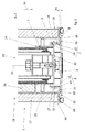
- the telescoping element 23 comprises an in FIG. 1 covert and in the FIGS. 2 to 5 illustrated pressure bar 5, which is coupled to the drive device 25.
- the pressure beam 5 is further connected to cover plates 27 of the telescoping element 23, of which a cover plate 27 in FIG. 1 is shown.
- cover plates 27 In the retracted state I cover the cover plates 27 partially covering the panels 26.
- the cover plates 27 By means of the drive device 25 laterally retracted or retracted.
- a gap 100 between a fixed wall 101 and the partition wall element 2 can be closed.
- the telescoping element 23 is in the extended state II.
- a visual and sound protection is achieved.
- FIGS. 2 to 5 For the sake of clarity, only one cover plate 27 or cladding plate 26 is partially shown, but in each case opposite cover plates 27 and cladding plates 26 are present.
- the pressure spar 5 is preferably formed as a profile, which is in particular extruded or extrusion-molded.
- the pressure bar 5 is screwed to the drive device 25 on an end face 30 of the pressure beam 5 by a fastening element 29. This eliminates or reduces the machining effort in the production of the pressure beam 5.
- a diaphragm profile 6 which forms the lateral end of the telescoping element 23 and conceals the pressure beam 5.
- the diaphragm profile 6 forms together in the FIGS. 2 to 5 shown and acting as elastic muffler 28 hollow chamber seals the side surface 3 of the partition wall element 2.
- the fastening element 29 is covered. This makes it possible that despite the simple production of the pressure beam 5, the partition wall element 2 has an attractive aesthetic design.
- the panel profile 6 extends substantially over the entire vertical height 52 of the cover plates 27.
- the panel profile 6 is extruded.
- the panel profile 6 can be easily adapted to the vertical height of the cover plates 27.
- a first and a second diaphragm holding means 7, 8 are formed monolithically with the remaining diaphragm profile 6.
- the diaphragm holding means 7, 8 extend over the entire vertical height of the diaphragm profile 6.
- pressure bar retaining means 9, 10, 11 are monolithically formed with the remaining pressure bar 5.
- the pressure strut holding means 9, 10, 11 extend over the entire vertical height of the pressure beam 5.
- the diaphragm profile 6 Due to the integration of the diaphragm retaining means 7, 8 in the diaphragm profile 6 and the integration of Druckholmhaltesch 9, 10, 11 in the pressure beam 5, the diaphragm profile 6 is held on the pressure spar 5 in a technically simple manner.
- the diaphragm retaining means 7, 8 extend into the interior of the telescoping element 23. In this way stops formed by the diaphragm retaining means 7, 8 and the pressure bar retaining means 9, 10, 11, which form the stop of the diaphragm profile 6 on the pressure spar 5, are not visible.
- the partition wall element 2 according to the invention FIG. 1 may have a motor extendable telescoping element 23 or a manually extendable telescopic element 23, depending on the design of the drive device 25.
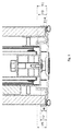
- the partition wall element 2 with the motor extendable telescopic element 23 and the partition wall element 2 with the manually extendable telescoping member 23 from the outside are identical. If there is no obstacle overlaps in the retracted state I according FIG. 1 the aperture profile 6 of the motor extendable telescopic element 23 slightly less with the cover plates 27 than the diaphragm profile 6 of the manually extendable telescoping member 23, as a comparison of Figures 2 and 4 shows. Otherwise, the external impression is identical even when retracted.
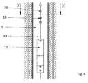
- the panel profile 6 covers, for example, spring elements 22, safety switch 35 and / or reed switch 36 of a motor-extendable telescoping element 23.
- the spring elements 22, the safety switch 35 and / or reed switch 36 are not visible to the viewer.
- the Spring elements 22, the safety switch 35 and / or reed switch 36 are arranged in the interior of the telescoping element 23.
- FIGS. 2 to 4 show a cross-sectional view of the partition wall element 2 FIG. 1 according to the line AA.
- FIG. 5 shows a cross-sectional view of the partition wall element FIG. 4 according to the line XX FIG. 1 ,
- a partition wall element 2 with a manually extendable telescoping element 23 and in the FIGS. 4 and 5 a partition wall element 2 is shown with a motor extendable telescoping element 23.
- the same diaphragm profile 6 can be used both in a manually and in a motor extendable telescoping element 23.
- the diaphragm profile 6 is in the Figures 2 and 3 in a first mounting position III and in the FIGS. 4 and 5 in a second mounting position IV.
- the diaphragm profile 6 is rotated in the first mounting position III in comparison to the diaphragm profile 6 in the second mounting position IV by 180 ° about a horizontal axis 53.
- the pressure beam 5 in a motor-extendable telescopic element 23 the same as in a manually extendable telescopic element 23.
- the partition wall element 22 with a manually extendable telescoping element 23 in a simple manner be converted into a partition wall member 22 with a motor extendable telescoping element 23.
- the pressure beam 5 has a U-shaped base profile 24 on which a first L-shaped wall portion 16 and a second L-shaped wall portion 17 of the pressure beam 5 are arranged.
- a first pressure strut holding means 9 and a second pressure strut holding means 10 are formed on the first wall section 16.
- a third pressure strut holding means 11 is formed at the second wall portion 17.
- a first stopper portion 18 and the second L-shaped wall portion 17, a second stop portion 19 connects.
- the first stop section 18 and the second stop section 19 extend at right angles to the L-shaped wall sections 16, 17, so that the short leg of an L-shaped wall section 16, 17 runs parallel to the stop section 18, 19.
- the panel profile 6 is captively arranged in or on the pressure spar 5.
- the diaphragm profile 6 has the first diaphragm holding means 7 and the second diaphragm holding means 8.
- the first and second diaphragm holding means 7, 8 are horizontally spaced.
- the first diaphragm holding means 7 is formed from a first web 12, at the distal end of a first latching lug 14 is arranged.
- the second diaphragm holding means 8 comprises a second web 13, the first web 12 and the second web 13 having approximately the same height H5 as in FIG FIG. 3 shown. At the second web 13, a second locking lug 15 is arranged.
- the webs 12,13 are formed so that they are flexurally elastic, that is, for example, when inserting the panel profile 6 in or on the pressure beam 5, by the configuration of the wall sections 16,17 causes to pivot elastically towards each other.
- the panel profile 6 can be clipped by a horizontal movement in the pressure spar 5.
- the diaphragm holding means 7, 8 form a positive connection with the pressure bar retaining means 9, 10, 11 in the telescoping direction 50.
- the diaphragm profile 6 is latched to the pressure beam 5.
- the pressure strut holding means 9, 10, 11 and the diaphragm holding means 7, 8 are formed asymmetrically to a center plane 51.
- the latching lugs 14, 15 are latched with pressure strut holding means 9, 10, 11, so that the panel profile 6 is held in the telescoping direction 50 on the pressure strut 5.
- FIG. 4 shown configuration of the distance A2 between the diaphragm profile 6 and the pressure spar 5 compared to in Fig. 2 shown configuration with the distance A1 between the diaphragm profile 6 and the pressure spar 5 has increased.
- the two diaphragm holding means 7, 8 respectively engage with different pressure bar retaining means 9, 10, 11.
- the first diaphragm holding means 7 is engaged with the first pressure bar retaining means 9
- the second diaphragm holding means 8 is engaged with the third pressure beam holding means 11 of the second wall portion 17.
- the first diaphragm holding means 7 is engaged with the third pressure beam holding means 11 of the second wall portion 17 and the second diaphragm holding means 8 is engaged with the second pressure bar retaining means 10 of the first wall section 16.
- the distance A1 of the first position V which deviates from the distance A2 of the second position VI, results.
- the second latching lug 15 is arranged at a height H2 on the second web 13, wherein the height H2 is less than the height H1 of the first latching lug 14 of the first web 12 is formed.
- the height H3 of the first pressure strut holding means 9 is greater than the height H6 of the third pressure hold means 11.
- the height H6 is again greater than the height H4 of the second pressure strut holding means 10.
- the height difference H1-H2 of the detents 14, 15 corresponds to the height difference H3- H6 of the first and third pressure strut holding means 9, 11 and the height difference H6-H4 of the third and the second pressure strut holding means 10, 11.
- the heights H1 to H6 are each related to a cover 33 of the panel profile 6.
- the diaphragm holding means 7, 8 can be clipped well both in the first and in the second mounting position III, IV, the first and second webs 12, 13 are aligned parallel to one another.
- the long legs of the first and second wall portions 16, 17 are formed parallel and spaced from the first and second web and serve as a guide for the locking lugs 14, 15th
- the panel profile 6 has the plate-like cover 33.
- the covering element 33 forms the side surface 3 of the partition wall element 2 together with the hollow chamber profiles 28.
- the covering element 33 conceals the pressure beam 5 in the vertical direction Outside facing surface of the panel profile 6 is configured consistently and advantageously has no visible from the outside fasteners, buttons or switches.
- the cover element 33 is adjoined by side parts 34, which cover a part of the cover plates 27 in a plan view of the front or rear side of the partition element.
- side parts 34 which cover a part of the cover plates 27 in a plan view of the front or rear side of the partition element.
- a cover is provided that both in a first position V of the diaphragm profile 6, the in Fig. 2 is shown, and in the second position VI, the in Fig. 4 is shown, a partial overlap of the cover plates 27 takes place, so that a transition between the cover 33 and the cover plates 27 is hidden in each case.
- the diaphragm profile is fixed substantially immovably on the pressure spar.
- a resilient element 21st arranged in the region of the first stop portion 18 and preferably in the region of the second stop portion 19 .
- This may be, for example, a rubber-like sealing tape.
- the resilient element 21 also serves for the vertical fixation of the panel profile 6 on the pressure beam 5.
- a static friction is generated by the resilient element 21, which prevents vertical movement of the panel profile 6.
- the concern of the panel profile 6 on the resilient element 21 on the pressure bar 5 also prevents a significant for the viewer movement of the panel profile 6 against the Teleskopieriques.
- the panel profile 6 in the in Fig. 4 On the other hand, the arrangement shown is movably arranged in the direction of the pressure beam 5, ie against the telescoping direction 50. If the panel profile 6 encounters an obstacle during extension, the panel profile 6 is moved counter to the telescoping direction 50 and actuates the safety switch 35 fastened to the pressure spar 5. In this way, the extension of the telescoping element 23 can be interrupted.
- the diaphragm profile 6 is movable, the diaphragm holding means 7, 8 in the second position VI against the telescoping direction 50 form-fitting manner to the pressure strut holding means 9, 10, 11 is formed. Likewise, the distal ends of the diaphragm holding means 7, 8 are spaced from the pressure beam 5 against the telescoping direction 50.
- spring elements 22 are arranged (s. FIG. 6 ), which act on the diaphragm profile 6 with a directed away from the pressure beam 5 force and in the in Fig. 3 shown second position VI against the second pressure strut holding means 10 and the third pressure strut holding means 11 press. This force can be overcome by the obstacle, so that the safety switch 35 is actuated.
- formed as leaf springs spring elements 22 are mounted on the end face 30 of the pressure beam 5.
- FIG. 4 illustrated second position VI thus corresponds to an exemption in which the diaphragm profile 6 against the telescoping 50 is actuated.
- FIG. 5 the shutter profile 6 is shown after actuation of the safety switch 35 in an operating position VII.
- the telescoping element 23 has reached an end position and thus the extended state II and abuts the wall 101.
- the diaphragm profile 6 has in the operating position VII the same distance A1 to the pressure beam 5 as in the first position V.
- seals can be used to the same extent in a manually extendable telescopic element 23 as well as a motor-extendable telescoping element 23 and the same sound insulation Offer.
- the operating position VII does not correspond to the first position V.
- the diaphragm profile 6 is not positively held in the operating position VII in Teleskopieriques 50, but the diaphragm profile 6 can by the force of the spring element 22 without lifting a form fit in the exemption FIG. 4 move back.
- the safety switch 35 can be reversibly actuated.
- the distal ends of the webs 12, 13 are provided, which previously come to rest against the pressure strut 5.
- the distal ends of the webs 12, 13 act as a stop.
- reed switch 36 (s. Fig. 6 ), which are mounted on an inner side of the cover 33.
- the reed switches 36 are intended to in the vicinity of the wall 101 to override an operation of the safety switch 35 and display so that no unwanted obstacle, but to be reached wall 101 has been reached.
- the reed switch 36 which cooperate with arranged on the wall 101 magnet, thus serve to distinguish between an unwanted obstacle and the wall 101.
- the extension of the telescoping element 23 is not immediately interrupted, but continued until the in FIG. 5 illustrated operating position VII has been achieved with the same sealing effect.
Landscapes
- Engineering & Computer Science (AREA)
- Architecture (AREA)
- Civil Engineering (AREA)
- Structural Engineering (AREA)
- Physics & Mathematics (AREA)
- Electromagnetism (AREA)
- Power-Operated Mechanisms For Wings (AREA)
- Building Environments (AREA)
- Specific Sealing Or Ventilating Devices For Doors And Windows (AREA)
Abstract
Description
- Die Erfindung betrifft ein Trennwandelement für eine Trennwandanlage, wobei das Trennwandelement ein in horizontaler Richtung ausfahrbares Teleskopierelement aufweist gemäß dem Oberbegriff des Patentanspruchs 1. Ebenfalls betrifft die Erfindung eine Trennwandanlage.
- Trennwandanlagen sind in verschiedenen Ausführungen bekannt. Eine Trennwandanlage umfasst in der Regel mehrere Trennwandelemente. Nebeneinander angeordnet können die Trennwandelemente zusammen eine Trennwand bilden.
- Vorgesehen ist bei einem ein seitliches Ende der Trennwand bildendes Trennwandelement ein randseitiges Teleskopierelement, welches durch eine Antriebsvorrichtung ausfahrbar ist. Das Teleskopierelement ist beim Schließen der Trennwand horizontal gegen eine feststehende Gebäudewand oder dergleichen ausfahrbar, um die Trennwandelemente horizontal gegeneinander zu verspannen und die verfügbare Restweite der betreffenden Gebäudeöffnung spaltfrei zu verschließen. Alternativ wird das Teleskopierelement gegen einen befestigten Anschlag ausgefahren, wenn sich statt einer feststehenden Gebäudewand eine andere Trennwand oder dergleichen anschließt, die nicht mit Spannkräften belastet werden darf.
- Bei teilautomatischen oder vollautomatischen Trennwandanlagen oder Trennwandelementen, im Folgenden zusammenfassend als automatische Trennwandanlagen oder Trennwandelemente bezeichnet, ist üblicherweise das Teleskopierelement mit Sicherheitsschaltern versehen, die bei Kontakt mit einem Hindernis den motorischen Antrieb des Teleskopierelements oder des übrigen Trennwandelements unterbrechen oder abschalten. Bei manuell betätigten Trennwandanlagen oder Trennwandelementen kann üblicherweise auf derartige Sicherheitsschalter verzichtet werden. Dies hat zur Folge, dass das mit dem Teleskopierelement ausgestattete Trennwandelement für eine manuelle Trennwandanlage konstruktiv anders ausgestaltet ist als das mit dem Teleskopierelement ausgestattete Trennwandelement für automatische Trennwandanlagen. Dies führt zu einer erhöhten Komplexität in der Variantenvielfalt derartigerTrennwandanlagen und den daraus resultierenden hohen Kosten.
- Ferner sind die Teleskopierelemente von manuellen und automatischen Trennwandelementen bedingt durch die entsprechenden unterschiedlichen Konstruktionen üblicherweise in der ästhetischen Anmutung voneinander verschieden, was insbesondere bei der Kombination von manuellen und automatischen Trennwandelementen oder Trennwandanlagen in einem Raum unerwünscht ist.
- Bei automatischen und manuellen Trennwandelementen ist eine Antriebsvorrichtung in einer in der Fertigung aufwändigen Art und Weise mit einem Druckholm verbunden.
- Es ist die Aufgabe der Erfindung, ein Trennwandelement für eine Trennwandanlage mit einem Teleskopierelement anzugeben, das auf technisch einfache Weise eine besonders ästhetisch ansprechende Gestaltung der teleskopierbaren Seitenfläche des Trennwandelements hervorruft.
- In den bevorzugten Ausführungsformen soll zudem erreicht werden, dass die Variantenvielfalt der Baugruppen, die zum Aufbau eines mit einem Teleskopierelement ausgestatteten Trennwandelements notwendig sind, reduziert wird und/oder die Funktionssicherheit eines derartigen Trennwandelements erhöht wird.
- Die Aufgabe wird gelöst durch den unabhängigen Anspruch 1. Vorteilhafte Weiterbildungen des Trennwandelements sind in den abhängigen Ansprüchen, der Beschreibung und in den Figuren angegeben. Dabei können die in der Beschreibung und in den Ansprüchen erwähnten Merkmale jeweils einzeln für sich oder in Kombination erfindungswesentlich sein. Ferner wird eine Trennwandanlage mit einem erfindungsgemäßen Trennwandelement unter Schutz gestellt, insbesondere eine Trennwandanlage mit einem Trennwandelement nach einem der Ansprüche 1 bis 15.
- Erfindungsgemäß ist vorgesehen, dass das Teleskopierelement einen Druckholm und ein Blendenprofil umfasst, wobei das Blendenprofil in oder an dem Druckholm gehalten ist, wobei das Blendenprofil wenigstens ein erstes Blendenhaltemittel umfasst, welches mit wenigstens einem korrespondierenden Druckholmhaltemittel des Druckholms zusammenwirkt.
- Das Teleskopierelement umfasst neben dem Druckholm ein Blendenprofil, das den Druckholm zumindest teilweise, bevorzugt vollständig, verdeckt. Hierbei bildet das Blendenprofil bevorzugt zumindest teilweise die teleskopierbare Seitenfläche des Trennwandelements. Dadurch dass das Blendenprofil vorgesehen ist, kann der Druckholm auf einfache Weise wie technisch notwendig ausgestaltet werden, ohne auf einen ästhetischen Eindruck Rücksicht nehmen zu müssen. Beispielsweise können notwendige Verschraubungen im Trennwandelement am Druckholm vorgenommen werden, welche dann vom Blendenprofil verdeckt werden. Indem das Blendenprofil am Druckholm gehalten ist, wird das Blendenprofil auf technisch einfache Art und Weise an dem übrigen Teleskopierelement befestigt. Der in dem Teleskopierelement zum Teleskopieren vorhandene Druckholm erhält durch das Halten des Blendenprofils eine zusätzliche technische Funktion. Besonders vorteilhaft ist es, dass das Blendenprofil und der Druckholm die dafür notwendigen Haltemittel umfassen. Somit ist auf technisch einfache Art und Weise eine besonders ästhetisch ansprechende Gestaltung der Seitenfläche eines Trennwandelements erreicht.
- Das Blendenhaltemittel und das Druckholmhaltemittel können form- und/oder kraftschlüssig zusammenwirken. Bevorzugt wirken das Blendenhaltemittel und das Druckholmhaltemittel formschlüssig, d. h. verrastend, zusammen.
- Für eine Verrastung im hier verwendeten Sinne ist es ausreichend, dass ein Formschluss, d. h. eine Verrastung, in einer Raumrichtung, insbesondere in einer Teleskopierrichtung, erfolgt. Die Verrastung kann demnach so ausgebildet sein, dass das Blendenprofil unbeweglich im oder am Druckholm angeordnet ist oder dass das Blendenprofil beweglich, insbesondere bezüglich des Abstands zwischen Druckholm und Blendenprofil und/oder in vertikaler Richtung, ausgebildet ist.
- Im Folgenden werden Raum- und Ortsangaben, wie "vertikal", "horizontal", "Vorder", "Rück", "seitlich", "Teleskopierrichtung", so verwendet, wie ein Betrachter einer montierten Trennwandanlage die Raum- und Ortsangaben verwenden würde.
- Bevorzugt sind mindestens zwei Blendenhaltemittel, d. h. ein erstes Blendenhaltemittel und ein zweites Blendenhaltemittel, vorgesehen, die insbesondere verrastend mit dazu korrespondierenden, mindestens zwei Druckholmhaltemitteln zusammenwirken. Sofern nicht anders angegeben, beziehen sich Merkmale, die sich auf das Blendenhaltemittel und/oder das Druckholmhaltemittel beziehen, auch die mindestens zwei Blendenhaltemittel und/oder die mindestens zwei Druckholmhaltemittel.
- Eine erfindungsgemäße Trennwandanlage kann ein oder mehrere Trennwandelemente, welche entlang eines Verfahrweges bewegbar angeordnet sind, umfassen. Der Verfahrweg kann insbesondere durch deckenseitige und/oder bodenseitige Schienen definiert sein, in welchen das oder die Trennwandelemente geführt sind. Die Trennwandelemente können zusammen eine Trennwand bilden. In der Trennwandanlage können bevorzugt bei demontierter Trennwand die Trennwandelemente parallel zueinander verstaut sein. Im montierten Zustand der Trennwand sind hingegen die Trennwandelemente dicht aneinander gereiht in einer Reihe angeordnet. Bevorzugt sind die Trennwandelemente durch Dichtleisten verspannt, welche gegen die Decke und/oder gegen den Boden ausgefahren sind.
- Ein erfindungsgemäßes Trennwandelement weist bevorzugt Laufrollen zum Verfahren in der Schiene der Trennwandanlage auf. Das Trennwandelement kann Verkleidungsplatten aufweisen, durch die insbesondere der überwiegende Teil einer Vorder- und Rückseite des Trennwandelements gebildet ist. Zwischen den Verkleidungsplatten kann ein Raum gebildet sein. Das Trennwandelement kann zumindest eine Dichtleiste, bevorzugt zwei Dichtleisten zum Verspannen gegen die Decke und/oder den Boden aufweisen.
- Bei einem vollautomatischen Trennwandelement erfolgen das Verschieben des Trennwandelementes und das Ausfahren des Teleskopierelements motorisch, während dies beides bei einem manuellen Trennwandelement manuell durch einen Bediener ausgeführt wird. Bei einem teilautomatischen Trennwandelement wird das Trennwandelement manuell verschoben, während das Teleskopierelement motorisch ausgefahren wird. Das motorische Ausfahren kann durch einen Elektromotor, d. h. elektrisch, erfolgen.
- Das Teleskopierelement dient dazu, in einer horizontalen Richtung ausgefahren zu werden. Somit kann das Teleskopierelement einen eingefahrenen und einen ausgefahrenen Zustand einnehmen. Im ausgefahrenen Zustand kann ein Spalt, der im eingefahrenen Zustand zwischen dem Trennwandelement und einem feststehenden Element, z. B. einer Gebäudewand, vorhanden war, überbrückt sein. Das Teleskopierelement bildet somit einen endseitigen Anschluss. Bevorzugt weist das Teleskopierelement Deckplatten auf. Die Deckplatten können zumindest teilweise die Vorder- und die Rückseite des Teleskopierelements bilden. Insbesondere zumindest im eingefahrenen Zustand überlagern sich die Deckplatten des Teleskopierelements mit den Verkleidungsplatten. Hierbei können zum einen die Deckplatten die Verkleidungsplatten umschließen. Somit nimmt das Teleskopierelement im eingefahrenen Zustand die Verkleidungsplatten teilweise in sich auf. Alternativ können sich die Deckplatten im eingefahrenen Zustand innerhalb der Verkleidungsplatten befinden. Somit ist in diesem Fall das Teleskopierelement im eingefahrenen Zustand zwischen den Deckplatten aufgenommen.
- Der Druckholm dient zur Verbindung einer Antriebsvorrichtung mit den Deckplatten. Die Antriebsvorrichtung dient zum Ausfahren des Teleskopierelements. Die Antriebsvorrichtung kann eine oder mehrere Ausfahreinheiten aufweisen. Der Druckholm kann sich derart in der Vertikalen erstrecken, dass die Deckplatten ausfahrbar sind. Beispielsweise ist es denkbar, dass sich der Druckholm zwischen 40% und 100%, bevorzugt zwischen 60% und 100%, besonders bevorzugt zwischen 75% und 100% über die vertikale Höhe der Deckplatten erstreckt. Der Druckholm kann eine zur Seitenfläche des Trennwandelements gerichtete Stirnfläche aufweisen. Die Antriebsvorrichtung kann manuell oder motorisch betreibbar ausgeführt sein.
- Es kann vorgesehen sein, dass das Blendenprofil zumindest die Stirnfläche des Druckholms abdeckt.
- Bevorzugt erstreckt sich das Blendenprofil an der Seitenfläche in etwa oder vollständig über die vertikale Höhe der Deckplatten. Hierbei kann es sein, dass das Blendenprofil am oberen und/oder unteren Ende geringfügig kürzer ausgebildet ist als die Deckplatten. So kann es sein, dass die Deckplatten am oberen und/oder unteren Ende zwischen 0,1 mm und 20 mm, bevorzugt zwischen 0,1 mm und 10 mm, besonders bevorzugt zwischen 0,1 mm und 5 mm, länger als das Blendenprofil ausgebildet sind. Hierdurch wird erreicht, dass bei einem Verkanten des Trennwandelements nur die weichen Deckplatten und nicht das Blendenprofil die Verkantung bilden.
- Zusätzlich oder alternativ kann das Blendenprofil an der Seitenfläche die Deckplatten in ihrer Breite überdecken. Somit kann sich das Blendenprofil an der Seitenfläche über die gesamte Breite und/oder im Wesentlichen über die vertikale Höhe der Deckplatten erstrecken. Hierdurch ist das Innere des Teleskopierelements durch das Blendenprofil abgedeckt und geschützt. Unterschiedliche technische Ausgestaltungen im Inneren des Trennwandelements, die z. B. dadurch herrühren, ob das Trennwandelement und/oder das Teleskopierelement manuell oder motorisch verfahren werden, sind für den Betrachter nicht sichtbar. Hierdurch können die Seitenflächen von automatischen und manuellen Trennwandelemente und/oder Trennwandanlagen trotz unterschiedlicher Konstruktionen im Inneren des Teleskopierelements in der ästhetischen Anmutung einander gleichen. Dies ist insbesondere bei der Kombination von manuellen und automatischen Trennwandanlagen in einem Raum erwünscht.
- Es ist denkbar, dass das Blendenprofil ein Abdeckelement aufweist. Das Abdeckelement bildet insbesondere die teleskopierbare Seitenfläche aus. Das Abdeckelement verläuft bevorzugt zumindest abschnittsweise senkrecht zur Vorder- oder Rückseite des Trennwandelements. Bevorzugt überdeckt das Abdeckelement zumindest den Druckholm.
- Das Abdeckelement ist bevorzugt durchgehend, d. h. öffnungsfrei, ausgestaltet. Das Abdeckelement kann mit zumindest einen plattenartigen Abschnitt ausgeformt sein. An einer Außenseite des Abdeckelements kann sich ein elastischer Schalldämpfer befinden.
- Es ist denkbar, dass an der Stirnfläche des Druckholms ein Befestigungselement, z. B. eine Schraube, zur Befestigung des Druckholms an der Antriebsvorrichtung angeordnet ist. Hierdurch kann der Druckholm besonders einfach an der Antriebsvorrichtung befestigt sein. Bevorzugt ist durch das Blendenprofil das Befestigungselement verdeckt. Somit wird der ästhetische Eindruck nicht gestört.
- Eine Haltestelle ist als eine Stelle definiert, an der das Blendenhaltemittel und das Druckholmhaltemittel formschlüssig verbunden sind. Die Haltestelle ist bevorzugt im Inneren des Teleskopierelements angeordnet. Insbesondere ist die Haltestelle für den Betrachter des Trennwandelements nicht sichtbar.
- Es kann vorgesehen sein, dass sich das Blendenhaltemittel von dem Abdeckelement nach innen ins Teleskopierelement erstreckt. Bevorzugt befindet sich das Blendenhaltemittel an einer Innenseite des Abdeckelements.
- Um auf eine technisch einfache Art und Weise das Blendenhaltemittel zur Verfügung zu stellen, kann vorgesehen sein, dass das Blendenhaltemittel einstückig und/oder materialeinheitlich, insbesondere monolitisch, in dem Blendenprofil integriert ist. So kann das Blendenhaltemittel einstückig und/oder materialeinheitlich, insbesondere monolithisch, mit dem Abdeckelement verbunden sein. Zusätzlich oder alternativ ist es denkbar, dass das Druckholmhaltemittel einstückig und/oder materialeinheitlich, insbesondere monolitisch, in dem Druckholm integriert ist. Hierdurch kann der Druckholm montagefreundlich hergestellt sein.
- Bevorzugt ist das Blendenprofil durch eine horizontale Bewegung an dem Druckholm montierbar, insbesondere verrastbar. Besonders bevorzugt ist das Blendenprofil nur durch eine horizontale Bewegung an dem Druckholm montierbar, insbesondere verrastbar. Besonders bevorzugt wird das Blendenprofil in den Druckholm eingeclipst. Hierdurch kann auf technisch einfache Art und Weise das Blendenprofil montierbar sein.
- Das Blendenprofil und/oder der Druckholm des erfindungsgemäßen Trennwandelements kann sowohl für eine Verwendung bei einem manuellen Trennwandelement als auch bei einem automatischen Trennwandelement geeignet sein, wodurch sich eine deutliche Komplexitätsreduktion für die Fertigung und Beschaffung von Bauelementen für Trennwandanlagen ergibt.
- Bei einem motorisch ausfahrbaren Teleskopierelement und/oder einem motorisch verschiebbaren Trennwandelement ist bevorzugt zumindest ein Sicherheitsschalter angeordnet. Der Sicherheitsschalter ist vorgesehen, um bei Kontakt des Teleskopierelements mit einem Hindernis die motorische Antriebsvorrichtung des Teleskopierelements und/oder den motorischen Antrieb des gesamten Trennwandelements zu unterbrechen oder abzuschalten. Somit wird beim Anfahren an ein Hindernis einen Schaltimpuls für eine Steuerung des Trennwandelements und/oder des Teleskopierelements erzeugt. Der Sicherheitsschalter ist bevorzugt an der Stirnfläche des Druckholms angeordnet. Bevorzugt verdeckt das Blendenprofil den Sicherheitsschalter.
- Das Blendenprofil kann zur Betätigung des Sicherheitsschalters vorgesehen sein. Bevorzugt um diese Funktionalität zu erreichen, kann vorgesehen sein, dass das Blendenhaltemittel und das Druckholhaltemittel derart zusammenwirken, dass das Blendenprofil entgegen der Teleskopierrichtung bezogen auf den Druckholm beweglich anordbar ist. Hierbei ist es denkbar, dass die Blendenhaltemittel und die Druckkholmhaltemittel entgegen der Teleskopierrichtung formschlussfrei zueinander anordbar sind. Insbesondere ist das Blendenhaltemittel derart von dem Druckholm beanstandet anordbar, dass der Sicherheitsschalter, insbesondere durch eine Bewegung des Blendenprofils entgegen der Teleskopierrichtung, betätigbar ist. Somit wirkt das Blendenprofil als ein Betätigungsmittel für den Sicherheitsschalter. Derart angeordnet kann das Blendenprofil eine Freistellung, in der der Sicherheitsschalter unbetätigt ist, und mindestens eine Betätigungsstellung, in der der Sicherheitsschalter betätigt ist und einen Schaltimpuls zur Unterbrechung oder Abschaltung des motorischen Antriebs oder der motorischen Antriebsvorrichtung erzeugt, einnehmen.
- Rein beispielhaft kann das Blendenprofil zur Betätigung des Sicherheitsschalters über einen Betätigungsweg W von 2 mm ≤ W ≤ 20 mm, bevorzugt 3 mm ≤ W ≤ 15 mm, besonders bevorzugt von 4 mm ≤ W ≤ 10 mm bewegbar sein.
- Bevorzugt ist das Blendenhaltemittel reversibel betätigbar. Das heißt, dass das Blendenprofil zwischen der Freistellung und der Betätigungsstellung hin und her bewegbar ist.
- Es ist denkbar, dass zwischen dem Blendenprofil und dem Druckholm ein Federelement angeordnet ist, welches das Blendenprofil mit einer vom Druckholm weg gerichteten Kraft beaufschlagt. Das Federelement kann dazu dienen, das Blendenprofil, sofern es außer Kontakt ist mit dem Hindernis, in der Freistellung zu halten. Zusätzlich oder alternativ kann das Federelement dazu dienen, das Blendenprofil von der Betätigungsstellung in die Freistellung zu bewegen.
- Damit das Federelement das Blendenprofil in die Freistellung bewegen kann, kann vorgesehen sein, dass das Blendenhaltemittel und das Druckholmhaltemittel in der Betätigungsstellung in Teleskopierrichtung formschlussfrei zueinander ausgebildet sind.
- Das Federelement kann an der Stirnfläche des Druckholms befestigt, z. B. angeschraubt, sein. Das Federelement ist insbesondere als eine Blattfeder ausgebildet. Es können auch mehrere Federelemente über die Stirnfläche des Druckholms verteilt sein. Bevorzugt überdeckt das Blendenprofil das Federelement bzw. die Federelemente.
- Als Sicherheitsschalter kann insbesondere ein Microschalter vorgesehen sein. Zusätzlich kann innen am Blendenprofil, insbesondere auf der Innenseite des Abdeckelements, zumindest ein magnetisch betätigbare Schalter befestigt, insbesondere aufgeklebt, sein. Der magnetisch betätigbaren Schalter, z. B. ein Reedschalter, kann dazu dienen, ein Hindernis von der Endlage des Trennwandelements, z. B. an einer Gebäudewand, zu unterscheiden. Hierzu sind an oder in der Gebäudewand Magnete angeordnet, die mit dem magnetisch betätigbaren Schalter zusammenwirken können. Der magnetisch betätigbare Schalter kann in der Nähe der Endlage den Schaltimpuls des Sicherheitsschalters übersteuern und so ein weiteres Ausfahren des Teleskopierelements in die Endlage ermöglichen. Hierdurch ist es möglich, einen genügend festen Anpressdruck zum Schallschutz und/oder zum Verspannen der Trennwand in der Endlage zu erreichen. Bevorzugt ist das Blendenprofil derart geformt, dass der magnetisch betätigbare Schalter für den Betrachter nicht sichtbar ist.
- Bevorzugt ist dasselbe Blendenprofil auch für ein manuell ausfahrbares Teleskopierelement verwendbar. Hierzu kann vorgesehen sein, dass das Druckholmhaltemittel und das Blendenhaltemittel derart zusammenwirken, dass das Blendenprofil in einer ersten Position in oder an dem Druckholm haltbar, insbesondere verrastbar, ist, in welcher insbesondere ein erster Abstand A1 zwischen einem ersten Anschlagabschnitt des Druckholms und dem Blendenprofil ausgebildet ist, und in einer zweiten Position in oder an dem Druckholm haltbar, insbesondere verrastbar, ist, in welcher insbesondere ein zweiter Abstand A2 zwischen einem ersten Anschlagabschnitt des Druckholms und dem Blendprofil ausgebildet ist. Das Blendenprofil kann dabei jeweils in Teleskopierrichtung am Druckholm gehalten sein. Anders ausgedrückt, kann das Blendenprofil in einer ersten und in einer zweiten Position an oder in dem Druckholm in der Teleskopierrichtung haltbar, insbesondere verrastbar, sein, wobei in der ersten Position das Blendenprofil einen ersten Abstand A1 entgegen der Teleskopierrichtung gegenüber dem Druckholm einnimmt und in der zweiten Position einen zweiten Abstand A2 entgegen der Teleskopierrichtung gegenüber dem Druckholm einnimmt. In der zweiten Position kann das Blendenprofil einen größeren Abstand zu dem Druckholm aufweisen als in der ersten Position. Der Abstand A2 kann größer sein als der Abstand A1.
- Bei dem ersten Abstand A1, welcher beispielsweise bei einem manuell ausfahrbares Teleskopierelement und/oder für ein manuell verschiebbares Trennwandelement ausgebildet ist, kann das Blendenprofil am Druckholm im Wesentlichen fixiert sein, während bei dem zweiten Abstand A2, welcher insbesondere bei einem motorisch ausfahrbaren Teleskopierelement und/oder einem motorisch verschiebbares Trennwandelement vorliegt, kann das Blendenprofil gegenüber dem Druckholm beweglich, insbesondere federnd, gelagert sein. Hierdurch lässt sich insbesondere dasselbe Blendenprofil sowohl für manuelle als auch für automatische Trennwandelemente verwenden, was zu einer deutlichen Komplexitätsreduktion in den zur Ausbildung eines Trennwandelements notwendigen Bauelementen führt.
- Die zweite Position kann der Freistellung entsprechen. Insbesondere entspricht jedoch die erste Position nicht der Betätigungsstellung. Zwar können bevorzugt der Anschlagabschnitt und das Blendenprofil in einer der möglichen Betätigungsstellungen einen ähnlichen oder denselben ersten Abstand A1 gegenüber dem Druckholm wie in der ersten Position aufweisen. Jedoch ist bevorzugt in der Betätigungsstellung das Blendenprofil anders als in der ersten Position nicht in Telekopierrichtung an dem Druckholm gehalten.
- Insbesondere ist das Blendenprofil in der ersten Position entgegen der Teleskopierrichtung fixiert. Anders ausgedrückt, ist in der ersten Position das Blendenprofil nur wenig oder gar nicht entgegen der Teleskopierrichtung bewegbar. So kann das Blendenprofil z. B. nur weniger als 2 mm, bevorzugt weniger als 1 mm, besonders bevorzugt weniger als 0,5 mm entgegen der Teleskopierrichtung bewegbar sein.
- Es kann sein, dass in der ersten Position und/oder in der Betätigungsstellung das Blendenprofil entgegen der Teleskopierrichtung an dem übrigen Teleskopierelement, insbesondere an dem Druckholm und/oder an den Deckplatten, anliegt. Hierbei kann das Blendenprofil unmittelbar anliegen. Z. B. kann ein distales Ende des Blendenhaltemittels an dem Druckholm anliegen. Alternativ oder zusätzlich können in der ersten Position und/oder in der Betätigungsstellung das Blendenprofil und der Druckholm über ein federelastisches Element, z. B. ein Dichtungsband, aneinander anliegen. Hierdurch kann eine störende Geräuschentwicklung verhindert sein. Das federelastische Element kann zudem eine Kraft auf den Formschluss des Blendenhaltemittels mit dem Druckholm in Teleskopierrichtung ausüben.
- Der Druckholm kann einen ersten Anschlagabschnitt und einen zweiten Anschlagabschnitt umfassen, an dem das Blendenprofil, insbesondere das Abdeckelement, bevorzugt unter Zwischenanordnung jeweils eines federelastischen Elements, anliegt. Somit können über mindestens zwei federelastische Elemente der Druckholm und das Blendenprofil in der ersten Position und/oder in der Betätigungsstellung aneinander anliegen.
- Vorzugsweise ist ein Erreichen der ersten Position ausgehend von der zweiten Position durch eine Bewegung des Blendenprofils entgegen der Teleskopierrichtung verhindert. Da in der ersten Position das Blendenprofil in Teleskopierrichtung, insbesondere formschlüssig, gehalten ist, so steht eine Bewegung ausgehend von der zweiten Position, d. h. der Freistellung, in die erste Position einer Reversiblität der Schalterbetätigung entgegen.
- Es ist denkbar, dass das Blendenprofil in einer ersten Montagestellung und in einer zweiten Montagestellung an dem Druckholm anordbar ist, wobei sich das Blendenprofil in der zweite Montagestellung um eine horizontale Achse gedreht im Vergleich zu der ersten Montagestellung befindet. Insbesondere ist das Blendenprofil hierbei um 180° gedreht. Bevorzugt ist die erste Montagestellung dazu vorgesehen, dass das Blendenprofil die erste Position einnimmt, und die zweite Montagestellung ist dazu vorgesehen, dass das Blendenprofil die zweite Position einnimmt.
- Besonders bevorzugt kann das Blendenprofil die erste Position nur in der ersten Montagestellung und/oder das Blendenprofil die zweite Position nur in der zweiten Montagestellung einnehmen. Hierzu können das Blendenprofil und/oder der Druckholm asymmetrisch in Bezug auf eine vertikale Mittelebene des Trennwandelements ausgestaltet sein. So kann in der ersten Montagestellung das Blendenhaltemittel mit einem ersten Druckholmhaltemittel und in der zweiten Montagestellung das Blendenhaltemittel mit einem weiteren Druckholmhaltemittel, das insbesondere zum ersten Druckholmhaltemittel bezogen auf die Mittelebene asymmetrisch ist, zusammenwirken. Durch diesen Aufbau ist es insbesondere möglich, dass in einer Betätigungsstellung zwar derselbe Abstand A1 eingenommen werden kann, ohne dass jedoch die erste Position eingenommen wird.
- Es ist denkbar, dass mindestens zwei Haltestellen vorgesehen sind, an denen jeweils ein Blendenhaltemittel und ein Druckholmhaltemittel zusammenwirken, wobei die Haltestellen horizontal voneinander beabstandet sind. Hierdurch kann eine mechanisch wackelarme Anordnung des Blendenprofils an dem Druckholm erreicht werden. Insbesondere sind sowohl in der ersten Position als auch in der zweiten Position jeweils zwei Haltestellen vorgesehen. Somit kann sowohl für vollautomatische, halbautomatische und manuelle Trennwandelemente eine wackelarme Anordnung erreicht werden. Besonders bevorzugt sind drei Haltestellen vorgesehen, durch die in der ersten und in der zweiten Position jeweils zwei Haltestellen zur Verfügung gestellt werden. Somit findet eine Haltestelle sowohl in der ersten als auch in der zweiten Position Verwendung. Die mindestens zwei Haltestellen können in demselben Abstand zu der vertikalen Mittelebene des Trennwandelements angeordnet sein.
- Bevorzugt wirken dieselben zumindest zwei Blendenhaltemittel, d. h. das erste und das zweiten Blendenhaltemittel, in der ersten und in der zweiten Position mit Druckholmhaltemitteln zusammen.
- Bevorzugt ist es vorgesehen, dass sich das Blendenhaltemittel in vertikaler Richtung über das Blendenprofil und/oder das Druckholmhaltemittel in vertikaler Richtung über den Druckholm erstreckt. Hierdurch kann die Funktionssicherheit des Trennwandelements erhöht werden, da ein Verdrehen des Blendenprofils gegenüber dem Druckholm verhindert ist. Das Blendenhaltemittel und/oder das Druckholmhaltemittel ist bevorzugt in vertikaler Richtung durchgehend ausgebildet. Alternativ kann das Blendenhaltemittel und/oder das Druckholmhaltemittel bevorzugt Unterbrechungen in gleichmäßige Abstände aufweisen. Durch diese Alternativen ist es möglich, den Druckholm und/oder das Blendenprofil an unterschiedliche vertikale Höhen der Deckplatten einfach anzupassen. Besonders bevorzugt sind der Druckholm mit dem Druckholmhaltemittel und/oder das Blendenprofil mit dem Blendenhaltemittel stranggepresst ausgeformt.
- Es kann sein, dass das Blendenprofil durch das federelastische Element gegen vertikales Verschieben gehindert ist. Das Blendenprofil und/oder der Druckholm ist hierbei derart gegen das federelastische Element gepresst, dass ein vertikales Verschieben durch Haftreibung verhindert ist. Diese Lösung ist insbesondere für ein Blendenprofil in der ersten Position und/oder in einer Betätigungsstellung gewählt.
- In der zweiten Position kann eine derartige Haftreibung fehlen. Es ist denkbar, dass das Blendenprofil einen Halter aufweist, der auf dem Federelement aufliegt. Hierdurch kann das Blendenprofil in der zweiten Position und/oder in einer Betätigungsstellung an einer vertikalen Verschiebung gehindert sein. Ebenfalls ist es denkbar, dass das Blendenprofil eines manuellen Trennwandelements mit dem Federelement ausgestattet ist. Diese Ausstattung kann der Geräuschreduzierung und/oder der Verhinderung einer vertikalen Verschiebung dienen.
- Bevorzugt weist das Blendenprofil Seitenteile auf, die die Deckplatten des Teleskopierelements, insbesondere auf der Vorder- und Rückseite des Teleskopierelements, überlappen. Hierdurch wird ein ästhetisch spaltfreier Übergang zwischen dem Blendenprofil und den Deckplatten erreicht. Insbesondere sind die Seitenteile derart ausgeformt, dass die Seitenteile sowohl in der ersten als auch in der zweiten Position und/oder über den Betätigungsweg die Deckplatten des Trennwandelements überlappen.
- Ferner kann vorgesehen sein, dass das erste Blendenhaltemittel einen ersten Steg und das zweite Blendenhaltemittel einen zweiten Steg umfassen. Der erste und der zweite Steg können insbesondere horizontal zueinander beanstandet sein und/oder sich in der Vertikalen jeweils über das Blendenprofil erstrecken. Hierdurch wird erreicht, dass eine besonders einfache und funktionssichere Ausgestaltung der Blendenhaltemittel ermöglicht wird.
- Zudem kann vorgesehen sein, dass der erste Steg und der zweite Steg parallel zueinander verlaufen. Hierdurch wird erreicht, dass ein einfaches und sicheres Montieren und Halten des Blendenprofils, insbesondere sowohl in der ersten als auch in der zweiten Montagestellung, ermöglicht wird. Der erste Steg und der zweite Steg können alternativ oder zusätzlich parallel zu der vertikalen Mittelebene des Blendenprofils verlaufen. Der erste und der zweite Steg können z. B. denselben Abstand von der vertikalen Mittelebene aufweisen.
- Ferner kann vorgesehen sein, dass das der erste Steg und der zweite Steg eine im Wesentlichen identische horizontale Höhe H aufweisen. Hierdurch wird erreicht, dass ein einfaches und sicheres Halten des Blendenprofils z. B. durch ein einfaches Einführen der Blendenhaltemittel, ermöglicht wird. Zudem können der erste und der zweite Steg derart an dem Blendenholm zur Anlage kommen, dass das Abdeckelement senkrecht zu den Deckplatten anordbar ist.
- Der erste Steg und/oder der zweite Steg können des Blendenprofils können biegeelastisch ausgebildet sein. Hierdurch kann auf einfache Art das Blendenprofil an dem Druckholm aufclipsbar sein.
- Es kann vorgesehen sein, dass das erste Blendenhaltemittel ein am Steg ausgeformtes Formschlussmittel, insbesondere eine vom ersten Steg abstehende Rastnase, aufweist und das zweite Blendenhaltemittel ein am zweiten Steg ausgeformtes zweites Formschlussmittel, insbesondere eine vom zweiten Steg abstehende zweite Rastnase, aufweist. Die Formschlussmittel, z. B. Nut oder Rastnase, können insbesondere derart angeordnet sein, dass die Formschlussmittel sowohl in der ersten als auch in der zweiten Montagestellung mit Druckholmmitteln zusammenwirken. Hierdurch wird erreicht, dass das Blendenprofil materialsparend und sicher gehalten ist.
- Ferner kann vorgesehen sein, dass das erste Formschlussmittel, insbesondere die erste Rastnase, auf einer ersten Höhe H1 am ersten Steg und das zweite Formschlussmittel, insbesondere die zweite Rastnase, auf einer zweiten Höhe H2 am zweiten Steg angeordnet sind, wobei die erste Höhe H1 von der zweiten Höhe H2 verschieden ist. Als Höhe H1, H2 wird der Abstand der Formschlussmittel zum Abdeckelement bezeichnet. Hierdurch kann beispielsweise die erste Position des Blendenprofils und die zweite Position des Blendenprofils im oder am Druckholm realisiert sein.
- Die erste Rastnase kann am distalen Ende des ersten Steges angeordnet sein. Hierdurch wird erreicht, dass durch die Anordnung einer ersten Rastnase am distalen Ende des ersten Steges ein besonders leichtes Einclipsen des Blendenprofils durch hohe Biegsamkeit ermöglicht wird. Alternativ oder zusätzlich kann die zweite Rastnase des zweiten Steges unterhalb des distalen Endes des zweiten Steges angeordnet sein. Hierdurch ist es möglich, dass das distale Ende des zweiten Steges als Anschlag wirkt, durch den ein Halten in der Teleskopierrichtung in der Betätigungsstellung verhindert ist.
- Ferner kann es sein, dass der Druckholm einen ersten Wandabschnitt und einen zweiten Wandabschnitt umfasst, an dem die Druckholmhaltemittel angeordnet sind. Der erste und/oder der zweite Wandabschnitt können L-förmig ausgestaltet sein, wobei insbesondere ein Schenkel des "L" einem distalen Ende eines Steges gegenüberliegt.
- Der erste Wandabschnitt des Druckholms und der zweite Wandabschnitt des Druckholms können zumindest in einem Abschnitt im Wesentlichen parallel zum ersten Steg des Blendenprofils und zum zweiten Steg des Blendenprofils verlaufen. Hierdurch wird erreicht, dass eine besonders einfache und funktionssichere Führung des Blendenprofils beim Verrasten und/oder während des Betätigungswegs mit dem Druckholm gewährleistet ist. Bevorzugt sind die Stege und die dazu korrespondierenden Wandabschnitte beabstandet voneinander angeordnet, so dass aufgrund der fehlenden Reibung keine störende Geräusche hervorgerufen werden.
- Ferner kann vorgesehen sein, dass die Druckholmhaltemittel ein erstes Druckholmhaltemittel, ein zweites Druckholmhaltemittel und ein drittes Druckholmhaltemittel umfassen, wobei bevorzugt das erste Druckholmhaltemittel und das zweite Druckholmhaltemittel am ersten Wandabschnitt des Druckholms sowie das dritte Druckholmhaltemittel am zweiten Wandabschnitt des Druckholms angeordnet sind. Bevorzugt sind dabei das erste, das zweite und das dritte Druckholmhaltemittel in unterschiedlichen Höhen bezogen auf das Abdeckelement angeordnet.
- Es kann sein, dass der Höhenunterschied zwischen dem ersten und dem zweiten Blendenhaltemittel dem Höhenunterschied zwischen dem ersten und dem dritten Druckholmhaltemittel und/oder dass der Höhenunterschied zwischen dem ersten und dem zweiten Blendenhaltemittel dem Höhenunterschied zwischen dem zweiten und dritten Druckholmhaltemittel entspricht. Hierdurch kann beispielsweise erreicht werden, dass die erste Position des Blendenprofils und die zweite Position des Blendenprofils im oder am Druckholm realisierbar ist, wobei diese definierten Positionen durch eine 180° Drehung des Blendenprofils herstellbar sind. Hierzu sind bevorzugt nur ein Druckholmhaltemittel an einem der Wandabschnitte und/oder nur zwei Blendenhaltemittel vorgesehen.
- Ferner kann vorgesehen sein, dass das Blendenprofil im Wesentlichen senkrecht zur vertikalen Mittelebene des Trennwandelements verläuft. Hierdurch wird erreicht, dass eine besonders ästhetische Anmutung der Seitenfläche bewirkt wird, als auch eine sichere Funktionsweise des Trennwandelements beim Anschlag der Seitenfläche an eine Gebäudewand oder den befestigten Anschlag.
- Die Erfindung wird nachfolgend anhand von Ausführungsbeispielen näher erläutert. Technische Merkmale mit gleicher Funktion sind in den Figuren mit denselben Bezugszeichen versehen. Es zeigen:
- Fig. 1
- eine erfindungsgemäße Trennwandanlage mit einem erfindungsgemäßen Trennwandelement in einer Frontansicht
- Fig. 2
- Querschnittsansicht durch ein erfindungsgemäßes Trennwandelement mit einem manuell ausfahrbaren Teleskopierelement gemäß A-A aus
Figur 1 , - Fig. 3
- dieselbe Ansicht wie in
Figur 2 , in der Höhen H1 bis H6 dargestellt sind, - Fig. 4
- Querschnittsansicht durch ein erfindungsgemäßes Trennwandelement mit einem automatisch ausfahrbaren Teleskopierelement in einer Freistellung gemäß A-A aus
Figur 1 - Fig. 5
- Querschnittsansicht durch ein erfindungsgemäßes Trennwandelement mit einem automatisch ausfahrbaren Teleskopierelement aus
Figur 4 in einer Betätigungsstellung gemäß X-X ausFigur 1 - Fig. 6
- ein Ausschnitt aus einem Längsschnitt gemäß B-B der
Figur 1 für das in denFiguren 4 und5 gezeigte Ausführungsbeispiel. - In
Fig. 1 ist grob schematisch eine erfindungsgemäße Trennwandanlage 1 und ein erfindungsgemäßes Trennwandelement 2 der Trennwandanlage 1 während dem Aufbau einer Trennwand abgebildet. Das Trennwandelement 2 ist z. B. deckenseitig über Laufrollen 32 in einer Schiene 31 geführt und umfasst deckenseitig sowie bodenseitig eine nicht dargestellte Dichtleiste. Die Dichtleisten sind gegen die Decke bzw. den Boden zum schalldichten Anschluss ausfahrbar und können das Trennwandelement 2 verspannen. - Das Trennwandelement 2 weist eine erste vertikale Seitenfläche 3 und eine zweite vertikale Seitenfläche 4 auf, wobei die erste Seitenfläche 3 im gezeigten Ausführungsbeispiel der
Fig. 1 teleskopierbar ist. - Das Trennwandelement 2 umfasst hierzu ein in horizontaler Richtung ausfahrbares Teleskopierelement 23, welches - in der Bildebene der
Fig. 1 - nach rechts in eine Teleskopierrichtung gemäß dem Pfeil 50 ausfahrbar ist. Die Ausfahrbewegung des Teleskopierelements 23 gegenüber dem übrigen Trennwandelement 2 wird mittels einer rein schematisch dargestellten und inFig. 1 durch eine Verkleidungsplatte 26 verdeckten und daher nur gestrichelt dargestellten Antriebsvorrichtung 25 erzeugt, welche manuell und/oder motorisch betätigbar ist. Die Antriebsvorrichtung 25 weist exemplarisch zwei Ausfahreinheiten 37 auf. Die Antriebsvorrichtung 25 umfasst einen manuellen und/oder elektromotorischen Antrieb (nicht dargestellt), der in eine der Ausfahreinheiten 37 integriert oder zwischen den Ausfahreinheiten angeordnet sein kann. Jede Ausfahreinheit 37 kann beispielsweise eine Spindelmutter, die von dem manuellen und/oder elektromotorischen Antrieb über eine Spindel angetrieben wird, umfassen. Die Spindelmutter kann beispielsweise über ein Scherengestänge mit dem Teleskopierelement 23 verbunden sein. In jeder Ausfahreinheit 37 bewegt sich durch die Rotation der Spindel die Spindelmutter entlang der Spindel, so dass das Teleskopierelement 23 in horizontaler Richtung seitlich aus dem übrigen Trennwandelement 2 herausfährt, so dass das Teleskopierelement 23 einen ausgefahrenen Zustand II einnehmen kann. Ebenfalls kann das Teleskopierelement 23 durch die Antriebsvorrichtung 25 wieder eingefahren werden und einen eingefahrenen Zustand I annehmen. InFigur 1 ist das Teleskopierelement 23 in dem eingefahrenen Zustand I dargestellt. - Das Teleskopierelement 23 umfasst einen in
Figur 1 verdeckten und in denFiguren 2 bis 5 dargestellten Druckholm 5, welcher mit der Antriebsvorrichtung 25 gekoppelt ist. Der Druckholm 5 ist des Weiteren mit Deckplatten 27 des Teleskopierelements 23 verbunden, von denen eine Deckplatte 27 inFigur 1 dargestellt ist. Im eingefahrenen Zustand I verdecken die Deckplatten 27 teilweise die Verkleidungsplatten 26. Über den Druckholm 5 werden die Deckplatten 27 mittels der Antriebsvorrichtung 25 seitlich aus- oder wieder eingefahren. Durch das Ausfahren des Telekopierelements 23 kann ein Spalt 100 zwischen einer feststehenden Wand 101 und dem Trennwandelement 2 geschlossen werden. Bei geschlossenen Spalt liegt das Teleskopierelement 23 in dem ausgefahrenen Zustand II vor. Hierdurch wird ein Sicht- und Schallschutz erreicht. Obwohl in denFiguren 2 bis 5 der Übersichtlichkeit halber teilweise nur jeweils eine Deckplatte 27 oder Verkleidungsplatte 26 dargestellt ist, sind jedoch jeweils gegenüberliegende Deckplatten 27 und Verkleidungsplatten 26 vorhanden. - Wie in den
Figuren 2 bis 4 dargestellt, ist der Druckholm 5 ist bevorzugt als Profil ausgebildet, welches insbesondere stranggepresst oder extrusionsgeformt ist. Der Druckholm 5 ist mit der Antriebsvorrichtung 25 an einer Stirnfläche 30 des Druckholms 5 durch ein Befestigungselement 29 verschraubt. Hierdurch entfällt oder reduziert sich der Zerspanungsaufwand bei der Herstellung des Druckholms 5. - Erfindungsgemäß ist ein Blendenprofil 6 vorgesehen, das den seitlichen Abschluss des Teleskopierelements 23 bildet und den Druckholm 5 verdeckt. Das Blendenprofil 6 bildet zusammen in den
Figuren 2 bis 5 dargestellten und als elastische Schalldämpfer 28 wirkenden Hohlkammerdichtungen die Seitenfläche 3 des Trennwandelements 2. Durch das Blendenprofil 6 wird das Befestigungselement 29 verdeckt. Hierdurch ist es möglich, dass trotz der einfachen Herstellung des Druckholms 5 das Trennwandelement 2 eine ansprechende ästhetische Gestaltung aufweist. - Wie in
Figur 1 dargestellt, erstreckt sich das Blendenprofil 6 im Wesentlichen über die gesamte vertikale Höhe 52 der Deckplatten 27. Das Blendenprofil 6 ist stranggepresst. Damit kann das Blendenprofil 6 einfach an die vertikale Höhe der Deckplatten 27 angepasst werden. - Wie in den
Figuren 2 bis 5 dargestellt, sind ein erstes und ein zweites Blendenhaltemittel 7, 8 monolithisch mit dem übrigen Blendenprofil 6 ausgeformt. Die Blendenhaltemittel 7, 8 erstrecken sich über die gesamte vertikale Höhe des Blendenprofils 6. Entsprechend sind Druckholmhaltemittel 9, 10, 11 monolithisch mit dem übrigen Druckholm 5 ausgeformt. Die Druckholmhaltemittel 9, 10, 11 erstrecken sich über die gesamte vertikale Höhe des Druckholms 5. Hierdurch sind das Blendenprofil 6 und der Druckholm 5 einfach skalierbar und sicher aneinander gehalten. Durch die Integration der Blendenhaltemittel 7, 8 in das Blendenprofil 6 und der Integration der Druckholmhaltemittel 9, 10, 11 in den Druckholm 5 ist auf technisch einfache Weise das Blendenprofil 6 an dem Druckholm 5 gehalten. Die Blendenhaltemittel 7, 8 erstrecken sich in das Innere des Teleskopierelements 23. Hierdurch sind durch die Blendenhaltemittel 7, 8 und die Druckholmhaltemittel 9, 10, 11 gebildete Haltestellen, die den Halt des Blendenprofils 6 an dem Druckholm 5 bilden, nicht sichtbar. - Das erfindungsgemäße Trennwandelement 2 gemäß
Figur 1 kann ein motorisch ausfahrbares Teleskopierelement 23 oder ein manuell ausfahrbares Teleskopierelement 23 aufweisen, je nach Ausbildung der Antriebsvorrichtung 25. Im ausgefahrenen Zustand II sind das Trennwandelement 2 mit dem motorisch ausfahrbaren Teleskopierelement 23 und das Trennwandelement 2 mit dem manuell ausfahrbaren Teleskopierelement 23 von außen identisch. Sofern kein Hindernis vorliegt, überlappt im eingefahrenen Zustand I gemäßFigur 1 das Blendenprofil 6 des motorisch ausfahrbaren Teleskopierelements 23 etwas weniger mit den Deckplatten 27 als das Blendenprofil 6 des manuell ausfahrbaren Teleskopierelements 23, wie ein Vergleich derFiguren 2 und4 zeigt. Ansonsten ist der äußere Eindruck auch im eingefahrenen Zustand I identisch. Hierdurch sind vollautomatische, teilautomatische und manuelle Trennwandelemente 2 von der äußeren Anmutung her im Wesentlichen identisch. So überdeckt das Blendenprofil 6 beispielsweise Federelemente 22, Sicherheitsschalter 35 und/oder Reedschalter 36 eines motorisch ausfahrbaren Teleskopierelements 23. Hierdurch sind die Federelemente 22, die Sicherheitsschalter 35 und/oder Reedschalter 36 für den Betrachter nicht sichtbar. Die Federelemente 22, die Sicherheitsschalter 35 und/oder Reedschalter 36 sind im Inneren des Teleskopierelements 23 angeordnet. - Die
Figuren 2 bis 4 zeigen eine Querschnittsansicht des Trennwandelements 2 ausFigur 1 gemäß der Linie A-A. DieFigur 5 zeigt eine Querschnittsansicht des Trennwandelements ausFigur 4 gemäß der Linie X-X ausFigur 1 . Hierbei ist in denFiguren 2 und3 ein Trennwandelement 2 mit einem manuell ausfahrbaren Teleskopierelement 23 und in denFiguren 4 und5 ein Trennwandelement 2 mit einem motorisch ausfahrbaren Teleskopierelement 23 dargestellt. Wie dieFiguren 2 bis 5 zeigen, kann dasselbe Blendenprofil 6 sowohl bei einem manuell als auch bei einem motorisch ausfahrbaren Teleskopierelement 23 verwendet werden. Hierzu befindet sich das Blendenprofil 6 in denFiguren 2 und3 in einer ersten Montagestellung III und in denFiguren 4 und5 in einer zweiten Montagestellung IV. Das Blendenprofil 6 ist in der ersten Montagestellung III im Vergleich zu dem Blendenprofil 6 in der zweiten Montagestellung IV um 180° um eine horizontale Achse 53 gedreht. Ebenfalls ist der Druckholm 5 bei einem motorisch ausfahrbaren Teleskopierelement 23 derselbe wie bei einem manuell ausfahrbaren Teleskopierelement 23. Somit können durch die Verwendung derselben Komponenten die Variantenvielfalt und damit die Lagerhaltung für das erfindungsgemäße Trennwandelement 2 gering gehalten werden. Zudem kann durch einen Austausch einer manuellen Antriebsvorrichtung 25 gegen eine motorische Antriebsvorrichtung 25, ein Montieren der Sicherheitsschalter 35, der Reedschalter 36 und ggf. der Federelemente 22 und eine 180° Drehung des Blendenprofils 6 das Trennwandelement 22 mit einem manuell ausfahrbaren Teleskopierelement 23 auf einfache Weise in ein Trennwandelement 22 mit einem motorisch ausfahrbaren Teleskopierelement 23 umgewandelt werden. - Wie in den
Figuren 2 bis 5 jeweils dargestellt, weist der Druckholm 5 ein U-förmiges Grundprofil 24 auf, an dem ein erster L-förmiger Wandabschnitt 16 und ein zweiter L-förmiger Wandabschnitt 17 des Druckholms 5 angeordnet sind. An dem ersten Wandabschnitt 16 sind ein erstes Druckholmhaltemittel 9 und ein zweites Druckholmhaltemittel 10 ausgeformt. An dem zweiten Wandabschnitt 17 ist ein drittes Druckholmhaltemittel 11 ausgebildet. - An dem ersten L-förmigen Wandabschnitt 16 schließt sich ein erster Anschlagabschnitt 18 und am zweiten L-förmigen Wandabschnitt 17 ein zweiter Anschlagabschnitt 19 an. Der erste Anschlagabschnitt 18 und der zweite Anschlagabschnitt 19 verlaufen rechtwinklig zu den L-förmigen Wandabschnitten 16,17, so dass der kurze Schenkel eines L-förmigen Wandabschnitts 16,17 parallel zum Anschlagabschnitt 18,19 verläuft.
- Das Blendenprofil 6 ist verliersicher im oder an dem Druckholm 5 angeordnet. Hierzu weist das Blendenprofil 6 das erste Blendenhaltemittel 7 und das zweites Blendenhaltemittel 8 auf. Das erste und das zweite Blendenhaltemittel 7, 8 sind horizontal beabstandet. In dem gezeigten Ausführungsbeispiel der
Figuren 2 bis 5 ist das erste Blendenhaltemittel 7 aus einem ersten Steg 12 gebildet, an dessen distalem Ende eine erste Rastnase 14 angeordnet ist. Das zweite Blendenhaltemittel 8 umfasst einen zweiten Steg 13, wobei der erste Steg 12 und der zweite Steg 13 in etwa die gleiche Höhe H5 aufweisen, wie inFigur 3 dargestellt. Am zweiten Steg 13 ist eine zweite Rastnase 15 angeordnet. Die Stege 12,13 sind so ausgebildet, dass sie biegeelastisch sind, d.h. dass sie beispielsweise beim Einsetzen des Blendenprofils 6 in oder an dem Druckholm 5, durch die Ausgestaltung der Wandabschnitte 16,17 bewirkt, elastisch aufeinander zu verschwenken. Hierdurch kann das Blendenprofil 6 durch eine horizontale Bewegung in den Druckholm 5 eingeclipst werden. Eingeclipst gehen die Blendenhaltemittel 7, 8 einen Formschluss mit den Druckholmhaltemitteln 9, 10, 11 in Teleskopierrichtung 50 ein. Hierdurch ist das Blendenprofil 6 an dem Druckholm 5 verrastet. - Die Druckholmhaltemittel 9, 10, 11 und die Blendenhaltemittel 7, 8 sind asymmetrisch zu einer Mittelebene 51 ausgebildet. Hierdurch ist es möglich, dass in der ersten Montagestellung III das Blendenprofil 6 eine erste Position V in Bezug auf den Druckholm 5 einnimmt, die in den
Figuren 2 und3 dargestellt ist, während in der zweiten Montagestellung IV das Blendenprofil 6 eine zweiten Position VI in Bezug auf den Druckholm 5 einnimmt, wie in derFigur 4 dargestellt. Hierbei sind in der ersten Position V als auch in der zweiten Position VI die Rastnasen 14, 15 mit Druckholmhaltemittel 9, 10, 11 verrastet, so dass das Blendenprofil 6 in der Teleskopierrichtung 50 an dem Druckholm 5 gehalten ist. Es ist ersichtlich, dass sich in der inFig. 4 gezeigten Konfiguration der Abstand A2 zwischen dem Blendenprofil 6 und dem Druckholm 5 verglichen mit der inFig. 2 gezeigten Konfiguration mit dem Abstand A1 zwischen dem Blendenprofil 6 und dem Druckholm 5 vergrößert hat. - Je nachdem ob die erste Position V oder die zweite Position VI eingenommen werden, verrasten die beiden Blendenhaltemittel 7, 8 jeweils mit unterschiedlichen Druckholmhaltemitteln 9, 10, 11. So ist in der ersten Position V das erste Blendenhaltemittel 7 im Eingriff mit dem ersten Druckholmhaltemittel 9 des ersten Wandabschnitts 16. In der ersten Position V ist das zweite Blendenhaltemittel 8 im Eingriff mit dem dritten Druckholmhaltemittel 11 des zweiten Wandabschnitts 17. In der zweiten Position VI hingegen ist das erste Blendenhaltemittel 7 im Eingriff mit dem dritten Druckholmhaltemittel 11 des zweiten Wandabschnitts 17 und das zweite Blendenhaltemittel 8 ist im Eingriff mit dem zweiten Druckholmhaltemittel 10 des ersten Wandabschnitts 16.
- Durch die Asymmetrie der Blendenhaltemittel 7, 8 und der Druckholmhaltemittel 9, 10, 11 ergibt sich der Abstand A1 der ersten Position V, der von dem Abstand A2 der zweiten Position VI abweicht. Hierbei ist die zweite Rastnase 15 ist auf einer Höhe H2 am zweiten Steg 13 angeordnet, wobei die Höhe H2 geringer als die Höhe H1 der ersten Rastnase 14 des ersten Stegs 12 ausgebildet ist. Entsprechend ist die Höhe H3 des ersten Druckholmhaltemittels 9 größer als die Höhe H6 des dritten Druckholhaltemittels 11. Die Höhe H6 ist wiederum größer als die Höhe H4 des zweiten Druckholmhaltemittels 10. Der Höhenunterschied H1 -H2 der Rastnasen 14, 15 entspricht hierbei dem Höhenunterschied H3-H6 des ersten und dritten Druckholmhaltemittels 9, 11 sowie dem Höhenunterschied H6-H4 des dritten und des zweiten Druckholmhaltemittels 10, 11. Die Höhen H1 bis H6 sind hierbei jeweils auf ein Abdeckelement 33 des Blendenprofils 6 bezogen.
- Damit die Blendenhaltemittel 7, 8 sowohl in der ersten als auch in der zweiten Montagestellung III, IV gut verclipsbar sind, sind der erste und der zweite Steg 12, 13 parallel zueinander ausgerichtet. Die langen Schenkel des ersten und zweiten Wandabschnitts 16, 17 sind parallel und beabstandet zu dem ersten und zweiten Steg ausgebildet und dienen als Führung für die Rastnasen 14, 15.
- Das Blendenprofil 6 weist das plattenartige Abdeckelement 33 auf. Das Abdeckelement 33 bildet zusammen mit den Hohlkammerprofilen 28 die Seitenfläche 3 des Trennwandelements 2. Hierbei verdeckt das Abdeckelement 33 den Druckholm 5. die Das Abdeckelement 33 verläuft im Wesentlichen in vertikaler Richtung senkrecht zu einer Wandebene 20 und zur Mittelebene 51 des Trennwandelements 2. Die nach außen weisende Oberfläche des Blendenprofils 6 ist durchgängig ausgestaltet und weist vorteilhafter Weise keine von außen sichtbaren Befestigungsmittel, Taster oder Schalter auf.
- An das Abdeckelement 33 schließen sich Seitenteile 34 an, die in einer Draufsicht auf die Vorder- oder Rückseite des Trennwandelements einen Teil der Deckplatten 27 überdecken. Hierbei ist eine derartige Überdeckung vorgesehen, dass sowohl in einer ersten Position V des Blendenprofils 6, die in
Fig. 2 gezeigt ist, und in der zweiten Position VI, die inFig. 4 gezeigt ist, eine teilweise Überdeckung der Deckplatten 27 erfolgt, so dass ein Übergang zwischen dem Abdeckelement 33 und den Deckplatten 27 jeweils verdeckt ist. - In der in
Fig. 2 gezeigten Position des Blendenprofils 6 ist das Blendenprofil im Wesentlichen unbeweglich am Druckholm fixiert. - Um zum einen eine verbesserte Fixierung mittels einer auf die Verrastung wirkende Vorspannung zu gewährleisten und eine akustische Entkopplung zwischen dem Blendenprofil 6 und dem Druckholm 5 zu bewirken, ist im Bereich des ersten Anschlagabschnitts 18 und bevorzugt auch im Bereich des zweiten Anschlagsabschnitts 19 ein federelastisches Element 21 angeordnet. Dies kann beispielsweise ein gummiartiges Dichtungsband sein. Das federelastische Element 21 dient zudem zur vertikalen Fixierung des Blendenprofils 6 an dem Druckholm 5. Hierbei wird durch das federelastische Element 21 eine Haftreibung erzeugt, die eine vertikale Bewegung des Blendenprofils 6 verhindert. Das Anliegen des Blendenprofils 6 über das federelastische Element 21 am Druckholm 5 verhindert zudem eine für den Betrachter wesentlich erscheinende Bewegung des Blendenprofils 6 entgegen der Teleskopierrichtung. Zusätzlich ist eine Bewegung des Blendenprofils 6 entgegen der Teleskopierrichtung durch ein Anschlagen der distalen Enden der Blendenhaltemittel 7, 8 an den kurzen Schenkeln der Wandabschnitte 16, 17 und/oder ein Anschlagen des Abdeckelements 33 an den Deckplatten 27 im Wesentlichen verhindert.
- Das Blendenprofil 6 in der in
Fig. 4 gezeigten Anordnung ist hingegen in Richtung auf den Druckholm 5, d. h. gegen die Teleskopierrichtung 50, beweglich angeordnet. Stößt das Blendenprofil 6 beim Ausfahren auf ein Hindernis, so wird das Blendenprofil 6 entgegen der Teleskopierrichtung 50 bewegt und betätigt den am Druckholm 5 befestigte Sicherheitsschalter 35. Hierdurch kann das Ausfahren des Teleskopierelements 23 unterbrochen werden. Damit das Blendenprofil 6 beweglich ist, sind die Blendenhaltemittel 7, 8 in der zweiten Position VI entgegen der Teleskopierrichtung 50 formschlussfrei zu den Druckholmhaltemitteln 9, 10, 11 ausgebildet. Ebenfalls sind die distalen Enden der Blendenhaltemittel 7, 8 von dem Druckholm 5 entgegen der Teleskopierrichtung 50 beabstandet. - Zwischen dem Blendenprofil 6 und dem Druckholm 5 sind Federelemente 22 angeordnet (s.
Figur 6 ), welche das Blendenprofil 6 mit einer vom Druckholm 5 weg gerichteten Kraft beaufschlagen und in die inFig. 3 gezeigte zweite Position VI gegen das zweite Druckholmhaltemittel 10 und das dritte Druckholmhaltemittel 11 drücken. Diese Kraft kann durch das Hindernis überwunden werden, so dass der Sicherheitsschalter 35 betätigbar ist. Wie inFigur 6 dargestellt, sind die als Blattfedern ausgeformten Federelemente 22 auf der Stirnfläche 30 des Druckholms 5 befestigt. - Die in
Figur 4 dargestellte zweite Position VI entspricht somit einer Freistellung, in der das Blendenprofil 6 entgegen der Teleskopierrichtung 50 betätigbar ist. InFigur 5 ist das Blendenprofil 6 nach der Betätigung des Sicherheitsschalters 35 in einer Betätigungsstellung VII dargestellt. Zudem hat das Teleskopierelement 23 eine Endlage und damit den ausgefahrenen Zustand II erreicht und liegt an der Wand 101 an. Das Blendenprofil 6 weist in der Betätigungsstellung VII denselben Abstand A1 zu dem Druckholm 5 auf wie in der ersten Position V. Somit können nicht dargestellte Dichtungen im gleichen Maße bei einem manuell ausfahrbaren Teleskopierelement 23 als auch bei einem motorisch ausfahrbaren Teleskopierelement 23 verwendet werden und denselben Schallschutz bieten. Die Betätigungsstellung VII entspricht jedoch nicht der ersten Position V. Vielmehr ist das Blendenprofil 6 in der Betätigungsstellung VII nicht in Teleskopierrichtung 50 formschlüssig gehalten, sondern das Blendenprofil 6 kann durch die Kraft des Federelements 22 ohne Aufhebung eines Formschluss sich in die Freistellung gemäßFigur 4 zurückbewegen. Somit kann der Sicherheitsschalter 35 reversibel betätigbar sein. Um einen Formschluss der zweiten Rastnase 15 mit dem ersten Druckholmhaltemittel 9 zu verhindern, sind die distalen Enden der Stege 12, 13 vorgesehen, die zuvor gegen den Druckholm 5 zur Anlage kommen. Somit wirken die distalen Enden der Stege 12, 13 als Anschlag. - Neben den Sicherheitsschaltern 35 sind Reedschalter 36 (s.
Fig. 6 ) vorgesehen, die auf einer Innenseite des Abdeckelements 33 befestigt sind. Die Reedschalter 36 sind dazu vorgesehen, in der Nähe der Wand 101 eine Betätigung des Sicherheitsschalter 35 zu übersteuern und so anzuzeigen, dass kein ungewolltes Hindernis, sondern die zu erreichende Wand 101 erreicht wurde. Die Reedschalter 36, die mit an der Wand 101 angeordneten Magneten zusammenwirken, dienen damit der Unterscheidung zwischen einem ungewollten Hindernis und der Wand 101. Bei Erreichen der Wand 101 wird anders als bei einem ungewollten Hindernis das Ausfahren des Teleskopierelements 23 nicht sofort unterbrochen, sondern weitergeführt, bis die inFigur 5 dargestellte Betätigungsstellung VII mit derselben Dichtwirkung erreicht worden ist. - Um ein vertikales Verschieben des Blendenprofils 6 in der zweiten Position VI gemäß
Figur 4 zu verhindern, ist innen an dem Blendenprofil 6 ein Halter befestigt, der an dem Federelement 22 aufliegt. -
- 1
- Trennwandanlage
- 2
- Trennwandelement
- 3
- erste vertikale Seitenfläche
- 4
- zweite vertikale Seitenfläche
- 5
- Druckholm
- 6
- Blendenprofil
- 7
- erstes Blendenhaltemittel
- 8
- zweites Blendenhaltemittel
- 9
- erstes Druckholmhaltemittel
- 10
- zweites Druckholmhaltemittel
- 11
- drittes Druckholmhaltemittel
- 12
- erster Steg
- 13
- zweiter Steg
- 14
- erste Rastnase
- 15
- zweite Rastnase
- 16
- erster Wandabschnitt
- 17
- zweiter Wandabschnitt
- 18
- erster Anschlagabschnitt
- 19
- zweiter Anschlagabschnitt
- 20
- Wandebene
- 21
- federelastisches Element
- 22
- Federelement
- 23
- Teleskopierelement
- 24
- Grundprofil
- 25
- Antriebsvorrichtung
- 26
- Verkleidungsplatte
- 27
- Deckplatte
- 28
- Schalldämpfer, Hohlkammerdichtung
- 29
- Befestigungselement
- 30
- Stirnfläche von 5
- 31
- Schiene
- 32
- Laufrolle
- 33
- Abdeckelement
- 34
- Seitenteil
- 35
- Sicherheitsschalter
- 36
- Reedschalter
- 37
- Ausfahreinheit von 25
- 50
- Teleskopierrichtung
- 51
- Mittelebene
- 52
- vertikale Höhe
- 53
- horizontale Achse
- 100
- Spalt
- 101
- Wand
- I
- eingefahrener Zustand
- II
- ausgefahrener Zustand
- III
- erste Montagestellung
- IV
- zweite Montagestellung
- V
- erste Position
- VI
- zweite Position, Freistellung
- VII
- Betätigungsstellung
Claims (15)
- Trennwandelement (2) für eine Trennwandanlage (1), wobei das Trennwandelement (2) ein in horizontaler Richtung ausfahrbares Teleskopierelement (23) aufweist,
dadurch gekennzeichnet, dass
das Teleskopierelement (23) einen Druckholm (5) und ein Blendenprofil (6) umfasst, wobei das Blendenprofil (6) in oder an dem Druckholm (5) gehalten ist, wobei das Blendenprofil (6) wenigstens ein erstes Blendenhaltemittel (7, 8) umfasst, welches, insbesondere verrastend, mit wenigstens einem korrespondierenden Druckholmhaltemittel (9,10,11) des Druckholms (5) zusammenwirkt. - Trennwandelement (2) nach Anspruch 1, dadurch gekennzeichnet, dass das Blendenprofil (6) ein Abdeckelement (33) aufweist, von dem das Blendenhaltemittel (7,8) sich nach innen ins Teleskopierelement (23) erstreckt, wobei insbesondere das Abdeckelement (33) zumindest abschnittsweise senkrecht zu einer Wandebene (20) des Trennwandelements (2) verläuft und/oder das Abdeckelement (33) zumindest den Druckholm (5) überdeckt.
- Trennwandelement (2) nach Anspruch 1 oder 2, dadurch gekennzeichnet, dass das Blendenhaltemittel (7, 8) einstückig und/oder materialeinheitlich, insbesondere monolitisch, in dem Blendenprofil (6) integriert ist.
- Trennwandelement (2) nach einem der vorhergehenden Ansprüche, dadurch gekennzeichnet, dass das Blendenprofil (6) durch eine horizontale Bewegung an dem Druckholm (5) montierbar, insbesondere verrastbar, ist.
- Trennwandelement (2) nach einem der vorhergehenden Ansprüche, dadurch gekennzeichnet, dass das Blendenhaltemittel (7, 8) und das Druckholhaltemittel (9, 10, 11) derart zusammenwirken, dass das Blendenprofil (6) entgegen einer Teleskopierrichtung (50) bezogen auf den Druckholm (5) beweglich anordbar ist, wobei insbesondere zwischen dem Blendenprofil (6) und dem Druckholm (5) ein Federelement (22) angeordnet ist, welches das Blendenprofil (6) mit einer vom Druckholm (5) weg gerichteten Kraft beaufschlagt.
- Trennwandelement (1) nach einem der vorhergehenden Ansprüche, dadurch gekennzeichnet, dass die Druckholmhaltemittel (9,10,11) und die Blendenhaltemittel (7,8) derart zusammenwirken, dass das Blendenprofil (6) in einer ersten Position (V) in oder an dem Druckholm (5) haltbar, insbesondere verrastbar, ist, in welcher ein erster Abstand (A1) zwischen einem ersten Anschlagabschnitt (18) des Druckholms (5) und dem Blendenprofil (6) ausgebildet ist und in einer zweiten Position (VI) in oder an dem Druckholm (5) haltbar, insbesondere verrastbar, ist, in welcher ein zweiter Abstand (A2) zwischen dem ersten Anschlagabschnitt (18) des Druckholms (5) und dem Blendprofil (6) ausgebildet ist.
- Trennwandelement (2) nach einem der vorhergehenden Ansprüche, dadurch gekennzeichnet, dass das Blendenprofil (6) in einer ersten Montagestellung (III) und in einer in einer zweiten Montagestellung (IV) an dem Druckholm anordbar ist, wobei sich das Blendenprofil (6) in der zweite Montagestellung (IV) um eine horizontale Achse (53) gedreht im Vergleich zu der ersten Montagestellung (III) befindet, wobei insbesondere nur in der ersten Montagestellung (III) die erste Position (V) durch das Blendenprofil (6) und/oder nur in der zweiten Montagestellung (IV) die zweite Position (VI) durch das Blendenprofil (6) einnehmbar ist.
- Trennwandelement (2) nach einem der vorhergehenden Ansprüche, dadurch gekennzeichnet, dass sich das Blendenhaltemittel (7, 8) in vertikaler Richtung über das Blendenprofil (6) und/oder das Druckholmhaltemittel (9, 10, 11) in vertikaler Richtung über den Druckholm (5) erstreckt.
- Trennwandelement (2) nach einem der vorhergehenden Ansprüche, dass das Blendenprofil (6) Seitenteile (34) aufweist, die insbesondere in der ersten und in der zweiten Position (V, VI) und/oder über einen Betätigungsweg W Deckplatten (27) des Trennwandelements (2) überlappen.
- Trennwandelement (2) nach einem der vorhergehenden Ansprüche, dadurch gekennzeichnet, dass ein zweites Blendenhaltemittel (8) vorgesehen ist, wobei das erste Blendenhaltemittel (7) einen ersten Steg (12) und das zweite Blendenhaltemittel (8) einen zweiter Steg (13) umfasst.
- Trennwandelement (2) nach einem der vorhergehenden Ansprüche, dadurch gekennzeichnet, dass der erste Steg (12) und der zweite Steg (13) parallel zueinander verlaufen.
- Trennwandelement (2) nach einem der vorhergehenden Ansprüche, dadurch gekennzeichnet, dass das erste Blendenhaltemittel (7) ein am Steg ausgeformtes Formschlussmittel, insbesondere eine vom ersten Steg (12) abstehende Rastnase (14), aufweist und das zweite Blendenhaltemittel (8) ein am zweiten Steg (13) ausgeformtes zweites Formschlussmittel, insbesondere eine vom zweiten Steg abstehende zweite Rastnase (15), aufweist, wobei insbesondere das erste Formschlussmittel (14) auf einer ersten Höhe (H1) am ersten Steg (12) und das zweite Formschlussmittel (15) auf einer zweiten Höhe (H2) am zweiten Steg (13) angeordnet sind, wobei die erste Höhe (H1) von der zweiten Höhe (H2) verschieden ist.
- Trennwandelement (2) nach einem der vorhergehenden Ansprüche, dadurch gekennzeichnet, dass der Druckholm (5) einen ersten Wandabschnitt (16) und einen zweiten Wandabschnitt (17) umfasst, an dem die Druckholmhaltemittel (9,10,11) angeordnet sind, wobei insbesondere der erste Wandabschnitt (16) des Druckholms (5) und der zweite Wandabschnitt (17) des Druckholms (5) zumindest in einem Abschnitt im Wesentlichen parallel zum ersten Steg (12) des Blendenprofils (6) und zum zweiten Steg (13) des Blendenprofils (6) verlaufen.
- Trennwandelement (2) nach einem der vorhergehenden Ansprüche, dadurch gekennzeichnet, dass die Druckholmhaltemittel (9,10,11) ein erstes Druckholmhaltemittel (9), ein zweites Druckholmhaltemittel (10) und ein drittes Druckholmhaltemittel (11) umfassen, wobei insbesondere das erste Druckholmhaltemittel (9) und das zweite Druckholmhaltemittel (10) am ersten Wandabschnitt (16) des Druckholms (5) sowie das dritte Druckholmhaltemittel (11) am zweiten Wandabschnitt (17) des Druckholms (5) angeordnet sind.
- Trennwandelement (2) nach einem der vorhergehenden Ansprüche, dadurch gekennzeichnet, dass der Druckholm (5) einen ersten Anschlagabschnitt (18) und einen zweiten Anschlagabschnitt (19) umfasst, an dem das Blendenprofil (6) bevorzugt unter Zwischenanordnung eines federelastischen Elements (21), anliegt.
Applications Claiming Priority (1)
| Application Number | Priority Date | Filing Date | Title |
|---|---|---|---|
| DE102015108663.8A DE102015108663A1 (de) | 2015-06-01 | 2015-06-01 | Trennwandelement |
Publications (2)
| Publication Number | Publication Date |
|---|---|
| EP3101192A1 true EP3101192A1 (de) | 2016-12-07 |
| EP3101192B1 EP3101192B1 (de) | 2021-07-14 |
Family
ID=56112838
Family Applications (1)
| Application Number | Title | Priority Date | Filing Date |
|---|---|---|---|
| EP16172304.4A Active EP3101192B1 (de) | 2015-06-01 | 2016-05-31 | Trennwandelement |
Country Status (3)
| Country | Link |
|---|---|
| US (1) | US9903112B2 (de) |
| EP (1) | EP3101192B1 (de) |
| DE (1) | DE102015108663A1 (de) |
Families Citing this family (2)
| Publication number | Priority date | Publication date | Assignee | Title |
|---|---|---|---|---|
| DE102015108663A1 (de) * | 2015-06-01 | 2016-12-01 | Dorma Deutschland Gmbh | Trennwandelement |
| US10494811B1 (en) * | 2018-09-07 | 2019-12-03 | Haworth, Inc. | Expandable wall start for a movable wall |
Citations (1)
| Publication number | Priority date | Publication date | Assignee | Title |
|---|---|---|---|---|
| DE3425484A1 (de) * | 1984-07-11 | 1986-01-23 | aboplan Viol und Partner GmbH, 2903 Bad Zwischenahn | Versetzbare trennwand aus wandelementen und verfahren zur herstellung und demontage der wandelemente |
Family Cites Families (15)
| Publication number | Priority date | Publication date | Assignee | Title |
|---|---|---|---|---|
| US3566559A (en) * | 1968-12-23 | 1971-03-02 | Advanced Equipment Corp | Demountable wall structure |
| DE7629217U1 (de) * | 1976-09-18 | 1977-01-27 | Planacord Gmbh & Co Kg, 2900 Oldenburg | Wandelement mit ausfahrbarem ausgleichsstueck |
| US4454690A (en) * | 1976-09-28 | 1984-06-19 | Panelfold, Inc. | Portable and operable wall system |
| US4277920A (en) * | 1976-09-28 | 1981-07-14 | Panelfold Doors, Inc. | Portable and operable wall systems |
| US4103463A (en) * | 1976-09-28 | 1978-08-01 | Panelfold Doors, Inc. | Portable wall system |
| JPS5428411A (en) * | 1977-08-04 | 1979-03-03 | Kouji Unayama | Device for fixing room partition wall |
| DE3619392A1 (de) * | 1986-06-09 | 1987-12-10 | Hueppe Gmbh | Zweischaliges teleskopelement einer beweglichen trennwand |
| US5167575A (en) * | 1989-08-23 | 1992-12-01 | Macdonald Ross P | Clean room including an internal partition system |
| US5228254A (en) * | 1991-01-18 | 1993-07-20 | Plascore, Inc. | Wall system |
| DE9200754U1 (de) * | 1992-01-23 | 1992-04-23 | Hüppe Form Sonnenschutz- und Raumtrennsysteme GmbH, 2900 Oldenburg | Vorrichtung zum Aus- und Einfahren einer Dichtleiste an einem beweglichen Trennwandelement |
| US5644877A (en) * | 1995-07-25 | 1997-07-08 | Wood; Richard J. | Demountable ceiling closure |
| FR2805296B1 (fr) * | 2000-02-17 | 2002-12-27 | Jean Paul Scherrer | Profile de structure, notamment pour cloisons |
| NL2010367C2 (nl) * | 2013-02-27 | 2014-08-28 | Maars Holding Bv | Wand. |
| WO2014133387A1 (en) * | 2013-02-27 | 2014-09-04 | Maars Holding B.V. | Partition wall system with clamping profile |
| DE102015108663A1 (de) * | 2015-06-01 | 2016-12-01 | Dorma Deutschland Gmbh | Trennwandelement |
-
2015
- 2015-06-01 DE DE102015108663.8A patent/DE102015108663A1/de active Pending
-
2016
- 2016-05-31 EP EP16172304.4A patent/EP3101192B1/de active Active
- 2016-05-31 US US15/169,223 patent/US9903112B2/en active Active
Patent Citations (1)
| Publication number | Priority date | Publication date | Assignee | Title |
|---|---|---|---|---|
| DE3425484A1 (de) * | 1984-07-11 | 1986-01-23 | aboplan Viol und Partner GmbH, 2903 Bad Zwischenahn | Versetzbare trennwand aus wandelementen und verfahren zur herstellung und demontage der wandelemente |
Also Published As
| Publication number | Publication date |
|---|---|
| DE102015108663A1 (de) | 2016-12-01 |
| US20160348363A1 (en) | 2016-12-01 |
| EP3101192B1 (de) | 2021-07-14 |
| US9903112B2 (en) | 2018-02-27 |
Similar Documents
| Publication | Publication Date | Title |
|---|---|---|
| EP2333218B1 (de) | Einrichtung zum Dämpfen der Relativbewegung bewegter Vorrichtungsteile, insbesondere von Schiebetüren | |
| EP1836358B1 (de) | Vorgefertigtes fassadenelement | |
| DE2743007A1 (de) | Sockelbalken fuer schiebetore | |
| WO2010081567A1 (de) | Schiebetürbeschlag für zweiflügelige schiebetür | |
| CH707332A2 (de) | Rahmensystem für ein Insekten- und/oder Pollenschutzgitter. | |
| EP3101192B1 (de) | Trennwandelement | |
| EP2088275B1 (de) | Seitendichtungsprofil insbesondere für Rahmenprofile und damit ausgestattete Schiebetüranlagen | |
| AT10312U1 (de) | Tragekonstruktion zur befestigung wenigstens eines möbelantriebs | |
| EP2400099A1 (de) | Thermisch isolierende Flügelanlage | |
| EP0853713B1 (de) | Gleitschiene | |
| EP0784144A1 (de) | Magnetische Türdichtung und Zusatzprofile zu deren Herstellung | |
| EP1091081A2 (de) | Führungsvorrichtung für einen Rollladen, ein Rollo oder dgl | |
| EP1860262A2 (de) | Verriegelungsvorrichtung für eine Fahrzeugtür | |
| DE102017005236A1 (de) | Fahrzeugtür mit höhenverstellbarer Fensterscheibe | |
| EP2453097A2 (de) | Verriegelungseinrichtung für ein Seitensektionaltor | |
| DE10000163C1 (de) | Als Vorsatzkasten ausgebildeter Rollladenkasten | |
| EP1870549A2 (de) | Sektionaltor | |
| DE3520577C2 (de) | Elektromechanische Sicherheitskontaktleiste für kraftbetätigte Tore | |
| EP1231345B1 (de) | Gesteuerte Verriegelungsvorrichtung und Eckumlenkung | |
| EP0047880A1 (de) | Schieberlüftung | |
| DE102012005295B3 (de) | Pfostenverbinder | |
| EP1762691B1 (de) | Abdichtung einer Tür- oder Fensterecke | |
| DE29702221U1 (de) | Schiebetür | |
| EP3708751B1 (de) | Führungssystem für schiebetüren | |
| EP0672811A1 (de) | Fehlbedienungssperre für das Betätigungsgestänge eines Fensters, einer Tür od. dgl. |
Legal Events
| Date | Code | Title | Description |
|---|---|---|---|
| PUAI | Public reference made under article 153(3) epc to a published international application that has entered the european phase |
Free format text: ORIGINAL CODE: 0009012 |
|
| STAA | Information on the status of an ep patent application or granted ep patent |
Free format text: STATUS: THE APPLICATION HAS BEEN PUBLISHED |
|
| AK | Designated contracting states |
Kind code of ref document: A1 Designated state(s): AL AT BE BG CH CY CZ DE DK EE ES FI FR GB GR HR HU IE IS IT LI LT LU LV MC MK MT NL NO PL PT RO RS SE SI SK SM TR |
|
| AX | Request for extension of the european patent |
Extension state: BA ME |
|
| RAP1 | Party data changed (applicant data changed or rights of an application transferred) |
Owner name: DORMAKABA DEUTSCHLAND GMBH |
|
| STAA | Information on the status of an ep patent application or granted ep patent |
Free format text: STATUS: REQUEST FOR EXAMINATION WAS MADE |
|
| 17P | Request for examination filed |
Effective date: 20170607 |
|
| RBV | Designated contracting states (corrected) |
Designated state(s): AL AT BE BG CH CY CZ DE DK EE ES FI FR GB GR HR HU IE IS IT LI LT LU LV MC MK MT NL NO PL PT RO RS SE SI SK SM TR |
|
| STAA | Information on the status of an ep patent application or granted ep patent |
Free format text: STATUS: EXAMINATION IS IN PROGRESS |
|
| 17Q | First examination report despatched |
Effective date: 20200317 |
|
| STAA | Information on the status of an ep patent application or granted ep patent |
Free format text: STATUS: EXAMINATION IS IN PROGRESS |
|
| GRAP | Despatch of communication of intention to grant a patent |
Free format text: ORIGINAL CODE: EPIDOSNIGR1 |
|
| STAA | Information on the status of an ep patent application or granted ep patent |
Free format text: STATUS: GRANT OF PATENT IS INTENDED |
|
| INTG | Intention to grant announced |
Effective date: 20210203 |
|
| GRAS | Grant fee paid |
Free format text: ORIGINAL CODE: EPIDOSNIGR3 |
|
| GRAA | (expected) grant |
Free format text: ORIGINAL CODE: 0009210 |
|
| STAA | Information on the status of an ep patent application or granted ep patent |
Free format text: STATUS: THE PATENT HAS BEEN GRANTED |
|
| AK | Designated contracting states |
Kind code of ref document: B1 Designated state(s): AL AT BE BG CH CY CZ DE DK EE ES FI FR GB GR HR HU IE IS IT LI LT LU LV MC MK MT NL NO PL PT RO RS SE SI SK SM TR |
|
| REG | Reference to a national code |
Ref country code: GB Ref legal event code: FG4D Free format text: NOT ENGLISH |
|
| REG | Reference to a national code |
Ref country code: DE Ref legal event code: R096 Ref document number: 502016013400 Country of ref document: DE |
|
| REG | Reference to a national code |
Ref country code: IE Ref legal event code: FG4D Free format text: LANGUAGE OF EP DOCUMENT: GERMAN |
|
| REG | Reference to a national code |
Ref country code: AT Ref legal event code: REF Ref document number: 1410771 Country of ref document: AT Kind code of ref document: T Effective date: 20210815 |
|
| REG | Reference to a national code |
Ref country code: LT Ref legal event code: MG9D |
|
| REG | Reference to a national code |
Ref country code: NL Ref legal event code: MP Effective date: 20210714 |
|
| PG25 | Lapsed in a contracting state [announced via postgrant information from national office to epo] |
Ref country code: SE Free format text: LAPSE BECAUSE OF FAILURE TO SUBMIT A TRANSLATION OF THE DESCRIPTION OR TO PAY THE FEE WITHIN THE PRESCRIBED TIME-LIMIT Effective date: 20210714 Ref country code: RS Free format text: LAPSE BECAUSE OF FAILURE TO SUBMIT A TRANSLATION OF THE DESCRIPTION OR TO PAY THE FEE WITHIN THE PRESCRIBED TIME-LIMIT Effective date: 20210714 Ref country code: HR Free format text: LAPSE BECAUSE OF FAILURE TO SUBMIT A TRANSLATION OF THE DESCRIPTION OR TO PAY THE FEE WITHIN THE PRESCRIBED TIME-LIMIT Effective date: 20210714 Ref country code: ES Free format text: LAPSE BECAUSE OF FAILURE TO SUBMIT A TRANSLATION OF THE DESCRIPTION OR TO PAY THE FEE WITHIN THE PRESCRIBED TIME-LIMIT Effective date: 20210714 Ref country code: FI Free format text: LAPSE BECAUSE OF FAILURE TO SUBMIT A TRANSLATION OF THE DESCRIPTION OR TO PAY THE FEE WITHIN THE PRESCRIBED TIME-LIMIT Effective date: 20210714 Ref country code: NO Free format text: LAPSE BECAUSE OF FAILURE TO SUBMIT A TRANSLATION OF THE DESCRIPTION OR TO PAY THE FEE WITHIN THE PRESCRIBED TIME-LIMIT Effective date: 20211014 Ref country code: PT Free format text: LAPSE BECAUSE OF FAILURE TO SUBMIT A TRANSLATION OF THE DESCRIPTION OR TO PAY THE FEE WITHIN THE PRESCRIBED TIME-LIMIT Effective date: 20211115 Ref country code: NL Free format text: LAPSE BECAUSE OF FAILURE TO SUBMIT A TRANSLATION OF THE DESCRIPTION OR TO PAY THE FEE WITHIN THE PRESCRIBED TIME-LIMIT Effective date: 20210714 Ref country code: BG Free format text: LAPSE BECAUSE OF FAILURE TO SUBMIT A TRANSLATION OF THE DESCRIPTION OR TO PAY THE FEE WITHIN THE PRESCRIBED TIME-LIMIT Effective date: 20211014 Ref country code: LT Free format text: LAPSE BECAUSE OF FAILURE TO SUBMIT A TRANSLATION OF THE DESCRIPTION OR TO PAY THE FEE WITHIN THE PRESCRIBED TIME-LIMIT Effective date: 20210714 |
|
| PG25 | Lapsed in a contracting state [announced via postgrant information from national office to epo] |
Ref country code: PL Free format text: LAPSE BECAUSE OF FAILURE TO SUBMIT A TRANSLATION OF THE DESCRIPTION OR TO PAY THE FEE WITHIN THE PRESCRIBED TIME-LIMIT Effective date: 20210714 Ref country code: LV Free format text: LAPSE BECAUSE OF FAILURE TO SUBMIT A TRANSLATION OF THE DESCRIPTION OR TO PAY THE FEE WITHIN THE PRESCRIBED TIME-LIMIT Effective date: 20210714 Ref country code: GR Free format text: LAPSE BECAUSE OF FAILURE TO SUBMIT A TRANSLATION OF THE DESCRIPTION OR TO PAY THE FEE WITHIN THE PRESCRIBED TIME-LIMIT Effective date: 20211015 |
|
| REG | Reference to a national code |
Ref country code: DE Ref legal event code: R097 Ref document number: 502016013400 Country of ref document: DE |
|
| PG25 | Lapsed in a contracting state [announced via postgrant information from national office to epo] |
Ref country code: DK Free format text: LAPSE BECAUSE OF FAILURE TO SUBMIT A TRANSLATION OF THE DESCRIPTION OR TO PAY THE FEE WITHIN THE PRESCRIBED TIME-LIMIT Effective date: 20210714 |
|
| PLBE | No opposition filed within time limit |
Free format text: ORIGINAL CODE: 0009261 |
|
| STAA | Information on the status of an ep patent application or granted ep patent |
Free format text: STATUS: NO OPPOSITION FILED WITHIN TIME LIMIT |
|
| PG25 | Lapsed in a contracting state [announced via postgrant information from national office to epo] |
Ref country code: SM Free format text: LAPSE BECAUSE OF FAILURE TO SUBMIT A TRANSLATION OF THE DESCRIPTION OR TO PAY THE FEE WITHIN THE PRESCRIBED TIME-LIMIT Effective date: 20210714 Ref country code: SK Free format text: LAPSE BECAUSE OF FAILURE TO SUBMIT A TRANSLATION OF THE DESCRIPTION OR TO PAY THE FEE WITHIN THE PRESCRIBED TIME-LIMIT Effective date: 20210714 Ref country code: RO Free format text: LAPSE BECAUSE OF FAILURE TO SUBMIT A TRANSLATION OF THE DESCRIPTION OR TO PAY THE FEE WITHIN THE PRESCRIBED TIME-LIMIT Effective date: 20210714 Ref country code: EE Free format text: LAPSE BECAUSE OF FAILURE TO SUBMIT A TRANSLATION OF THE DESCRIPTION OR TO PAY THE FEE WITHIN THE PRESCRIBED TIME-LIMIT Effective date: 20210714 Ref country code: CZ Free format text: LAPSE BECAUSE OF FAILURE TO SUBMIT A TRANSLATION OF THE DESCRIPTION OR TO PAY THE FEE WITHIN THE PRESCRIBED TIME-LIMIT Effective date: 20210714 Ref country code: AL Free format text: LAPSE BECAUSE OF FAILURE TO SUBMIT A TRANSLATION OF THE DESCRIPTION OR TO PAY THE FEE WITHIN THE PRESCRIBED TIME-LIMIT Effective date: 20210714 |
|
| 26N | No opposition filed |
Effective date: 20220419 |
|
| PG25 | Lapsed in a contracting state [announced via postgrant information from national office to epo] |
Ref country code: IT Free format text: LAPSE BECAUSE OF FAILURE TO SUBMIT A TRANSLATION OF THE DESCRIPTION OR TO PAY THE FEE WITHIN THE PRESCRIBED TIME-LIMIT Effective date: 20210714 |
|
| REG | Reference to a national code |
Ref country code: CH Ref legal event code: PL |
|
| PG25 | Lapsed in a contracting state [announced via postgrant information from national office to epo] |
Ref country code: MC Free format text: LAPSE BECAUSE OF FAILURE TO SUBMIT A TRANSLATION OF THE DESCRIPTION OR TO PAY THE FEE WITHIN THE PRESCRIBED TIME-LIMIT Effective date: 20210714 Ref country code: LU Free format text: LAPSE BECAUSE OF NON-PAYMENT OF DUE FEES Effective date: 20220531 Ref country code: LI Free format text: LAPSE BECAUSE OF NON-PAYMENT OF DUE FEES Effective date: 20220531 Ref country code: CH Free format text: LAPSE BECAUSE OF NON-PAYMENT OF DUE FEES Effective date: 20220531 |
|
| PG25 | Lapsed in a contracting state [announced via postgrant information from national office to epo] |
Ref country code: IE Free format text: LAPSE BECAUSE OF NON-PAYMENT OF DUE FEES Effective date: 20220531 |
|
| PG25 | Lapsed in a contracting state [announced via postgrant information from national office to epo] |
Ref country code: HU Free format text: LAPSE BECAUSE OF FAILURE TO SUBMIT A TRANSLATION OF THE DESCRIPTION OR TO PAY THE FEE WITHIN THE PRESCRIBED TIME-LIMIT; INVALID AB INITIO Effective date: 20160531 |
|
| PG25 | Lapsed in a contracting state [announced via postgrant information from national office to epo] |
Ref country code: MK Free format text: LAPSE BECAUSE OF FAILURE TO SUBMIT A TRANSLATION OF THE DESCRIPTION OR TO PAY THE FEE WITHIN THE PRESCRIBED TIME-LIMIT Effective date: 20210714 Ref country code: CY Free format text: LAPSE BECAUSE OF FAILURE TO SUBMIT A TRANSLATION OF THE DESCRIPTION OR TO PAY THE FEE WITHIN THE PRESCRIBED TIME-LIMIT Effective date: 20210714 |
|
| PG25 | Lapsed in a contracting state [announced via postgrant information from national office to epo] |
Ref country code: TR Free format text: LAPSE BECAUSE OF FAILURE TO SUBMIT A TRANSLATION OF THE DESCRIPTION OR TO PAY THE FEE WITHIN THE PRESCRIBED TIME-LIMIT Effective date: 20210714 |
|
| PGFP | Annual fee paid to national office [announced via postgrant information from national office to epo] |
Ref country code: GB Payment date: 20240521 Year of fee payment: 9 |
|
| PGFP | Annual fee paid to national office [announced via postgrant information from national office to epo] |
Ref country code: DE Payment date: 20240521 Year of fee payment: 9 |
|
| PGFP | Annual fee paid to national office [announced via postgrant information from national office to epo] |
Ref country code: AT Payment date: 20240522 Year of fee payment: 9 |
|
| PGFP | Annual fee paid to national office [announced via postgrant information from national office to epo] |
Ref country code: FR Payment date: 20240528 Year of fee payment: 9 |
|
| PGFP | Annual fee paid to national office [announced via postgrant information from national office to epo] |
Ref country code: BE Payment date: 20240521 Year of fee payment: 9 |
|
| PG25 | Lapsed in a contracting state [announced via postgrant information from national office to epo] |
Ref country code: MT Free format text: LAPSE BECAUSE OF FAILURE TO SUBMIT A TRANSLATION OF THE DESCRIPTION OR TO PAY THE FEE WITHIN THE PRESCRIBED TIME-LIMIT Effective date: 20210714 |