EP3101190A1 - Trennwandmodul einer trennwand - Google Patents
Trennwandmodul einer trennwand Download PDFInfo
- Publication number
- EP3101190A1 EP3101190A1 EP16172296.2A EP16172296A EP3101190A1 EP 3101190 A1 EP3101190 A1 EP 3101190A1 EP 16172296 A EP16172296 A EP 16172296A EP 3101190 A1 EP3101190 A1 EP 3101190A1
- Authority
- EP
- European Patent Office
- Prior art keywords
- module
- vertical
- profiles
- profile
- partition
- Prior art date
- Legal status (The legal status is an assumption and is not a legal conclusion. Google has not performed a legal analysis and makes no representation as to the accuracy of the status listed.)
- Granted
Links
- 238000005192 partition Methods 0.000 title claims abstract description 65
- 230000013011 mating Effects 0.000 claims abstract description 34
- 238000007789 sealing Methods 0.000 claims description 19
- 239000000725 suspension Substances 0.000 claims description 13
- 238000005452 bending Methods 0.000 claims description 11
- 238000000034 method Methods 0.000 claims description 6
- 230000000087 stabilizing effect Effects 0.000 claims description 4
- 238000003780 insertion Methods 0.000 description 7
- 230000037431 insertion Effects 0.000 description 7
- 230000008901 benefit Effects 0.000 description 6
- 230000007246 mechanism Effects 0.000 description 5
- 230000009467 reduction Effects 0.000 description 5
- 238000004519 manufacturing process Methods 0.000 description 4
- 230000009471 action Effects 0.000 description 3
- 230000015572 biosynthetic process Effects 0.000 description 3
- 238000009434 installation Methods 0.000 description 3
- 230000002730 additional effect Effects 0.000 description 2
- 238000000926 separation method Methods 0.000 description 2
- 230000006978 adaptation Effects 0.000 description 1
- 230000000295 complement effect Effects 0.000 description 1
- 238000010276 construction Methods 0.000 description 1
- 238000005520 cutting process Methods 0.000 description 1
- 230000001419 dependent effect Effects 0.000 description 1
- 238000006073 displacement reaction Methods 0.000 description 1
- 230000006872 improvement Effects 0.000 description 1
- 238000009413 insulation Methods 0.000 description 1
- 230000003993 interaction Effects 0.000 description 1
- 239000002184 metal Substances 0.000 description 1
- 238000004080 punching Methods 0.000 description 1
- 230000002787 reinforcement Effects 0.000 description 1
- 230000006641 stabilisation Effects 0.000 description 1
- 238000011105 stabilization Methods 0.000 description 1
- 230000003068 static effect Effects 0.000 description 1
- 238000003860 storage Methods 0.000 description 1
- 238000003466 welding Methods 0.000 description 1
Images

Classifications
-
- E—FIXED CONSTRUCTIONS
- E04—BUILDING
- E04B—GENERAL BUILDING CONSTRUCTIONS; WALLS, e.g. PARTITIONS; ROOFS; FLOORS; CEILINGS; INSULATION OR OTHER PROTECTION OF BUILDINGS
- E04B2/00—Walls, e.g. partitions, for buildings; Wall construction with regard to insulation; Connections specially adapted to walls
- E04B2/74—Removable non-load-bearing partitions; Partitions with a free upper edge
- E04B2/7407—Removable non-load-bearing partitions; Partitions with a free upper edge assembled using frames with infill panels or coverings only; made-up of panels and a support structure incorporating posts
- E04B2/7416—Removable non-load-bearing partitions; Partitions with a free upper edge assembled using frames with infill panels or coverings only; made-up of panels and a support structure incorporating posts with free upper edge, e.g. for use as office space dividers
- E04B2/7422—Removable non-load-bearing partitions; Partitions with a free upper edge assembled using frames with infill panels or coverings only; made-up of panels and a support structure incorporating posts with free upper edge, e.g. for use as office space dividers with separate framed panels without intermediary support posts
-
- E—FIXED CONSTRUCTIONS
- E04—BUILDING
- E04B—GENERAL BUILDING CONSTRUCTIONS; WALLS, e.g. PARTITIONS; ROOFS; FLOORS; CEILINGS; INSULATION OR OTHER PROTECTION OF BUILDINGS
- E04B2/00—Walls, e.g. partitions, for buildings; Wall construction with regard to insulation; Connections specially adapted to walls
- E04B2/74—Removable non-load-bearing partitions; Partitions with a free upper edge
- E04B2/7407—Removable non-load-bearing partitions; Partitions with a free upper edge assembled using frames with infill panels or coverings only; made-up of panels and a support structure incorporating posts
-
- E—FIXED CONSTRUCTIONS
- E04—BUILDING
- E04B—GENERAL BUILDING CONSTRUCTIONS; WALLS, e.g. PARTITIONS; ROOFS; FLOORS; CEILINGS; INSULATION OR OTHER PROTECTION OF BUILDINGS
- E04B2/00—Walls, e.g. partitions, for buildings; Wall construction with regard to insulation; Connections specially adapted to walls
- E04B2/74—Removable non-load-bearing partitions; Partitions with a free upper edge
- E04B2/76—Removable non-load-bearing partitions; Partitions with a free upper edge with framework or posts of metal
- E04B2/78—Removable non-load-bearing partitions; Partitions with a free upper edge with framework or posts of metal characterised by special cross-section of the frame members as far as important for securing wall panels to a framework with or without the help of cover-strips
- E04B2/7854—Removable non-load-bearing partitions; Partitions with a free upper edge with framework or posts of metal characterised by special cross-section of the frame members as far as important for securing wall panels to a framework with or without the help of cover-strips of open profile
- E04B2/789—Removable non-load-bearing partitions; Partitions with a free upper edge with framework or posts of metal characterised by special cross-section of the frame members as far as important for securing wall panels to a framework with or without the help of cover-strips of open profile of substantially U- or C- section
-
- E—FIXED CONSTRUCTIONS
- E04—BUILDING
- E04B—GENERAL BUILDING CONSTRUCTIONS; WALLS, e.g. PARTITIONS; ROOFS; FLOORS; CEILINGS; INSULATION OR OTHER PROTECTION OF BUILDINGS
- E04B2/00—Walls, e.g. partitions, for buildings; Wall construction with regard to insulation; Connections specially adapted to walls
- E04B2/74—Removable non-load-bearing partitions; Partitions with a free upper edge
- E04B2/82—Removable non-load-bearing partitions; Partitions with a free upper edge characterised by the manner in which edges are connected to the building; Means therefor; Special details of easily-removable partitions as far as related to the connection with other parts of the building
- E04B2/821—Connections between two opposed surfaces (i.e. floor and ceiling) by means of a device offering a restraining force acting in the plane of the partition
- E04B2/822—Elastic connections, e.g. inflated joints
-
- E—FIXED CONSTRUCTIONS
- E04—BUILDING
- E04B—GENERAL BUILDING CONSTRUCTIONS; WALLS, e.g. PARTITIONS; ROOFS; FLOORS; CEILINGS; INSULATION OR OTHER PROTECTION OF BUILDINGS
- E04B2/00—Walls, e.g. partitions, for buildings; Wall construction with regard to insulation; Connections specially adapted to walls
- E04B2/74—Removable non-load-bearing partitions; Partitions with a free upper edge
- E04B2/82—Removable non-load-bearing partitions; Partitions with a free upper edge characterised by the manner in which edges are connected to the building; Means therefor; Special details of easily-removable partitions as far as related to the connection with other parts of the building
- E04B2/821—Connections between two opposed surfaces (i.e. floor and ceiling) by means of a device offering a restraining force acting in the plane of the partition
- E04B2/824—Connections between two opposed surfaces (i.e. floor and ceiling) by means of a device offering a restraining force acting in the plane of the partition restrained elastically at one surface and inelastically at the opposing surface
-
- E—FIXED CONSTRUCTIONS
- E04—BUILDING
- E04B—GENERAL BUILDING CONSTRUCTIONS; WALLS, e.g. PARTITIONS; ROOFS; FLOORS; CEILINGS; INSULATION OR OTHER PROTECTION OF BUILDINGS
- E04B2/00—Walls, e.g. partitions, for buildings; Wall construction with regard to insulation; Connections specially adapted to walls
- E04B2/74—Removable non-load-bearing partitions; Partitions with a free upper edge
- E04B2/82—Removable non-load-bearing partitions; Partitions with a free upper edge characterised by the manner in which edges are connected to the building; Means therefor; Special details of easily-removable partitions as far as related to the connection with other parts of the building
- E04B2/827—Partitions constituted of sliding panels
-
- E—FIXED CONSTRUCTIONS
- E04—BUILDING
- E04B—GENERAL BUILDING CONSTRUCTIONS; WALLS, e.g. PARTITIONS; ROOFS; FLOORS; CEILINGS; INSULATION OR OTHER PROTECTION OF BUILDINGS
- E04B2/00—Walls, e.g. partitions, for buildings; Wall construction with regard to insulation; Connections specially adapted to walls
- E04B2/74—Removable non-load-bearing partitions; Partitions with a free upper edge
- E04B2/82—Removable non-load-bearing partitions; Partitions with a free upper edge characterised by the manner in which edges are connected to the building; Means therefor; Special details of easily-removable partitions as far as related to the connection with other parts of the building
- E04B2/828—Connections between partitions and structural walls
Definitions
- the present invention relates to a partition wall module of a partition wall for covering an opening in a building structure, and to a method for mounting a partition wall module according to the present invention.
- partitions are usually provided as mobile partition systems in order to be able to separate corresponding smaller units in a large space by means of individual partition modules.
- these smaller units are not only visually but also acoustically separated from each other or decoupled.
- the known partition modules are provided standardized for this purpose and are manufactured uniformly.
- such partition modules are equipped with a module frame, which is provided on both sides with cover plates.
- cover plates Of course, an additional insulation for better acoustic decoupling can be made available between the cover plates, ie within the module frame.
- a disadvantage of the known solutions for partition modules is that they are usually very expensive to manufacture. In addition, a corresponding strength and thus a concomitant weight of the partition modules is difficult to undercut. This is due in particular to the fact that the module frame must have a high stability in order to be able to provide sufficient stability both in the static application situation and during the movement into the desired separating position.
- a partition wall module for a partition wall for covering an opening in a building structure.
- the partition wall module on a module frame of at least two vertical profiles and at least two horizontal profiles.
- a cover plate is attached to the module frame on both sides.
- a partition wall module according to the invention is characterized in that the horizontal profiles have a contact section at each end, which is in contact with a mating contact section of a vertical profile in at least partially form-fitting fastened contact for attachment of the horizontal profiles on the vertical profiles.
- An inventive separation profile has a known basic structure.
- a module frame is also provided here, which specifies a frame structure in order to ensure a corresponding attachment of the cover plate can.
- vertical profiles and horizontal profiles are provided to construct the module frame.
- the terminology of the vertical profile refers to a vertical arrangement of the vertical profile in installation situation.
- the terminology of the horizontal profile refers to an installation situation of the horizontal profile in a horizontal orientation.
- the module frame is preferably constructed such that the vertical profiles with the horizontal profiles after their connection in the installation situation to each other are substantially at right angles.
- each of the horizontal profiles is equipped with a contact section at each end. Since the horizontal profiles, like the vertical profiles, are usually designed with corresponding longitudinal extent, they have two ends with, accordingly, in total also two contact sections. The same applies to the vertical profiles, which also have at least at the respective end a mating contact portion.
- the correlation of contact sections and mating contact sections is now provided according to the invention. These correlate in a manner that they at least partially the fastening contact for the fastening horizontal profiles on the vertical profiles provide form-fitting training contact.
- This positive contact can be made in a variety of ways. For example, a nesting of the contact portion and the mating contact portion at least partially provide this desired form fit for attachment available. Of course, an additional action form this positive connection or reinforce it.
- a possible solution for this is when, for example, the contact portion is tab-shaped and is inserted into a corresponding tab slot of the mating contact portion. Already by this insertion of the at least partially positive fit is provided for the attachment available.
- plastic deformation of the contact section in the form of the tab is now possible, for example, in order in this way to be able to achieve an even better positive locking and thus a higher stability of the module frame.
- any description of a correlation between contact element and mating contact element also applies in the reverse manner, so that the kinematic reversal includes the same functionality, of course, within the scope of the scope of the present application.
- this refers to the thickness of the bulkhead module, so that a reduction in the thickness of the module frame may be followed by a reduction in the thickness of the bulkhead module.
- the reduction of the geometric dimensions and the weight also means that the new and inventive partition wall modules can be transported in an increased charge quantity.
- the contact sections of all horizontal profiles are identical to one another and / or the mating contact sections of all vertical profiles are identical to one another.
- the vertical profiles and / or the Horizontal profiles can be used in this way in both orientations in an identical manner.
- all contact portions with all mating contact portions in the inventive at least partially positively fastened contact can be brought.
- the applicability of the correlation between different horizontal profiles and different vertical profiles is further enhanced.
- not only the mating contact portions and the contact portions, but also all horizontal profiles or all vertical profiles are identical or substantially identical. However, differences may exist in particular with regard to the longitudinal extension and thus the geometric dimensions of the horizontal profiles or the vertical profiles.
- the contact sections are designed as contact tabs which extend through the mating contact sections in the form of tab slots in order to form a section-wise positive connection for the fastening.
- a tab is in the context of this embodiment, in particular a flat, elongated extension with a flat top and a flat bottom.
- a corresponding tab slot forms a complementary contour for this tab, so that the insertion of the tab in the tab slot with as little play around the tab around is possible. In particular, this is a clearance fit, which provides the desired positive connection as a plug connection available.
- this section-wise positive locking can be further improved by the insertion subsequently by an action, for example a plastic deformation, with regard to stability become.
- the formation of the contact portions or the mating contact portions is possible in this embodiment in the production, for example by sheet metal cutting or punching.
- At least one of the contact sections has a bending region which forms the fastening positive connection by plastic deformation.
- the bending region is arranged between the end portion of the contact portion and the base body of the horizontal profile, in particular with a reduced cross-section. If, for example, after insertion in accordance with the preceding paragraph, a force is applied to a tab slot, a plastic deformation can take place within the bending area. Specifically, the action of bending is based on a rotational movement so that a part of the contact portion is bent upward while at the same time another part of the contact portion is bent down.
- each vertical profile has at least two vertical telescope sections which overlap one another in the longitudinal extension direction of the vertical profile, wherein the Length of the overlap is variable.
- U profiles can then be pushed into one another in the vertical profile in order to form the vertical telescope sections in this way.
- an adaptation of the longitudinal extent of the vertical profiles can be carried out in this way.
- a lengthening of the cover plates can be made to perform the desired adjustment even in place on the site for the partition module.
- additional fastening means may be provided to connect the individual vertical telescoping sections together in the desired longitudinal extension relative position.
- a partition wall module between a top horizontal profile which forms an upper end of the module frame, and a lower horizontal profile which forms the lower end of the module frame, arranged a third horizontal profile and fixed to the vertical profiles for stabilizing the module frame is.
- the module frame can be a simple rectangle
- the stability is further increased by the provision of a third and centrally arranged horizontal profile.
- the central horizontal profile may have a parallel or substantially parallel orientation, and in particular be identical or substantially identical to the other two horizontal profiles in terms of its geometric extent.
- an employed and thus oblique orientation of the central horizontal profile provides an even stronger stabilizing effect for the module frame.
- a mounting interface can also be provided in the middle horizontal profile in order, for example, to fasten or store mechanical units in the form of an adjustment mechanism.
- an adjustment mechanism can bring advantages, for example, if sealing lips are to be mounted variably in a retracted position and an extended position.
- a partition wall module in the upper horizontal profile at least three bearing interfaces for the attachment of suspension devices for the movable suspension of the partition module are formed on a ceiling of the building.
- these bearing interfaces are actually used.
- a simple and especially provided with little friction displacement functionality for the partition module in associated rails are provided.
- the suspension with a single suspension is conceivable.
- This is designed in particular as a central suspension, so that a transverse locations of the partition module in the suspension is possible by the corresponding central arrangement of the third bearing interface. This is especially for a particularly simple and inexpensive training the rail system with respect to the storage position of the partition module in the rail system advantage.
- These individual bearing interfaces may be formed as holes, preferably also as elongated holes, in order to be able to additionally provide a corresponding fine adjustment of the relative positioning of the individual suspension devices.
- At least the upper horizontal profile has a profile nose, in which the cover plate is hooked by means of hook devices.
- This profile nose can be, for example, a locking projection or a section of a corresponding U-profile.
- the hook device of the cover plate may be, for example, an inverted U-profile to be hooked in a corresponding manner simple, inexpensive and fast in the associated profile nose.
- a self-stabilizing arrangement can be achieved by the weight of the cover plate in this way.
- the cover plate may additionally have plastic strips, which provide a corresponding contact with the module frame after hanging in the profile nose available and are formed in particular acoustically decoupled manner.
- the vertical profiles have a latching element for a latching of locking lugs of vertical sealing strips for the attachment of these vertical sealing strips on the vertical profiles.
- these locking elements are designed over the entire longitudinal extent of the vertical profiles. The same applies preferably for the entire longitudinal extension of the sealing strips with respect to the formation of the locking lugs.
- These sealing strips can be provided in particular with magnetic tapes to be able to enter according to tongue and groove with the adjacent partition module an even better connection. In particular, the goal of this sealing strips, the acoustic decoupling of the two separated space areas in a building.
- a horizontal sealing lip is arranged, in particular extendable manner, for a sealing of the partition module against the ceiling and / or the bottom of the building. This means that after reaching the partition module in its final covering position, for example by means of an adjustment mechanism, these sealing lips can be extended. This is a vertical extension movement. In other words, the sealing lips are now pressed up against the ceiling and down against the floor of the building to further improve the acoustic decoupling of the two separate room sections in addition to a stabilizing effect of the partition module.
- the method according to the invention brings about the same advantages as have been explained in detail with reference to a partition wall module according to the invention.
- the steps of suspending the cover plates may be provided.
- the order in which the fastening contact is made are essentially free.
- the vertical profile can be finished connected, and then the connection on the second side with the second vertical profile are provided.
- all insertion steps between contact sections and mating contact sections can first be completed in order finally to be able to complete the final action, for example bending over the individual contact sections around bending areas.
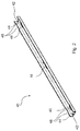
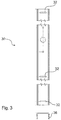
- FIG. 1 embodiments are shown which a partition module 10 with two vertical profiles 30 according to Fig. 3 and three horizontal profiles 40 according to FIG Fig. 2 represent.
- FIG. 2 embodiments are shown which a partition module 10 with two vertical profiles 30 according to Fig. 3 and three horizontal profiles 40 according to FIG Fig. 2 represent.
- a vertical profile 30 is provided, so that now a total of three horizontal profiles 40 according to Fig. 2 with tab-shaped contact portions 42 can be inserted into corresponding tab slots as mating contact portions 32. Already here forms by plugging a corresponding form-fitting and thus attaching contact between the contact portions 42 and the mating contact portions 32. Subsequently, a second vertical profile 30 is arranged in the same way at the opposite end of the horizontal profiles 40, so that finally, in particular by an additional bending of the individual contact portions 42 to a bending region 44 further reinforcement of the positive fastening situation can be achieved.
- a sealing lip 80 is now attached to the upper side and the underside of the module frame 20, which in these embodiments is designed to be retractable and extendable by means of a scissors mechanism.
- sealing strips 70 are latched on the two vertical profiles 30 via associated latching lugs 72 in corresponding latching elements 36 of the vertical profiles 30.
- latching lugs 72 are tongue-and-groove systems in order to be able to provide the best possible acoustic seal even in the vertical orientation of the partition wall module 10.
- the cover plates 50 can be hung on both sides, in particular a corresponding hook device 52 in associated profile lugs 48 according to Fig. 2 be hung.
- This suspension is simple, fast and inexpensive and the stabilization is done in particular by the weight of the cover plate 50.
Landscapes
- Engineering & Computer Science (AREA)
- Architecture (AREA)
- Physics & Mathematics (AREA)
- Electromagnetism (AREA)
- Civil Engineering (AREA)
- Structural Engineering (AREA)
- Building Environments (AREA)
- Specific Sealing Or Ventilating Devices For Doors And Windows (AREA)
Abstract
Description
- Die vorliegende Erfindung betrifft ein Trennwandmodul einer Trennwand zum Abdecken einer Öffnung in einem Baukörper sowie ein Verfahren für die Montage eines Trennwandmoduls gemäß der vorliegenden Erfindung.
- Es ist bekannt, dass in Baukörpern große Räume abtrennbar ausgestaltet werden sollen. Dafür werden üblicherweise Trennwände als mobile Trennwandsysteme zur Verfügung gestellt, um mithilfe einzelner Trennwandmodule entsprechende kleinere Einheiten in einem großen Raum abtrennen zu können. Insbesondere sind diese kleineren Einheiten nicht nur optisch, sondern auch akustisch voneinander getrennt bzw. entkoppelt. Die bekannten Trennwandmodule sind hierfür standardisiert zur Verfügung gestellt und werden einheitlich hergestellt. Üblicherweise sind solche Trennwandmodule mit einem Modulrahmen ausgestattet, welcher an beiden Seiten mit Abdeckplatten versehen ist. Selbstverständlich kann zwischen den Abdeckplatten, also innerhalb des Modulrahmens, noch eine zusätzliche Isolierung zur besseren akustischen Entkopplung zur Verfügung gestellt werden.
- Nachteilhaft bei den bekannten Lösungen für Trennwandmodule ist es, dass diese üblicherweise sehr aufwendig in der Herstellung sind. Darüber hinaus wird eine entsprechende Stärke und damit ein einhergehendes Gewicht der Trennwandmodule nur schwer unterschreitbar. Dies ruht insbesondere auf der Tatsache, dass der Modulrahmen eine hohe Stabilität aufweisen muss, um sowohl in der statischen Einsatzsituation, als auch während der Bewegung in die gewünschte abtrennende Position, eine ausreichende Stabilität zur Verfügung stellen zu können.
- Es ist Aufgabe der vorliegenden Erfindung, die voranstehend beschriebenen Nachteile zumindest teilweise zu beheben. Insbesondere ist es Aufgabe der vorliegenden Erfindung, in kostengünstiger und einfacher Weise die Fertigung des Trennwandmoduls weiter zu verbessern.
- Voranstehende Aufgabe wird gelöst durch ein Trennwandmodul mit den Merkmalen des Anspruchs 1 sowie ein Verfahren mit den Merkmalen des Anspruchs 11. Weitere Merkmale und Details der Erfindung ergeben sich aus den Unteransprüchen, der Beschreibung und den Zeichnungen. Dabei gelten Merkmale und Details, die im Zusammenhang mit dem erfindungsgemäßen Trennwandmodul beschrieben sind, selbstverständlich auch im Zusammenhang mit dem erfindungsgemäßen Verfahren und jeweils umgekehrt, so dass bezüglich der Offenbarung zu den einzelnen Erfindungsaspekten stets wechselseitig Bezug genommen wird bzw. werden kann.
- Erfindungsgemäß wird ein Trennwandmodul vorgesehen für eine Trennwand zum Abdecken einer Öffnung in einem Baukörper. Hierfür weist das Trennwandmodul einen Modulrahmen aus zumindest zwei Vertikalprofilen und zumindest zwei Horizontalprofilen auf. Dabei ist an dem Modulrahmen auf beiden Seiten jeweils eine Abdeckplatte befestigt. Ein erfindungsgemäßes Trennwandmodul zeichnet sich dadurch aus, dass die Horizontalprofile an jedem Ende einen Kontaktabschnitt aufweisen, welcher jeweils mit einem Gegenkontaktabschnitt eines Vertikalprofils in zumindest abschnittsweise formschlüssig befestigendem Kontakt steht für eine Befestigung der Horizontalprofile an den Vertikalprofilen.
- Ein erfindungsgemäßes Trennprofil weist eine bekannte Grundstruktur auf. So ist auch hier ein Modulrahmen vorgesehen, welcher eine Rahmenstruktur vorgibt, um eine entsprechende Befestigung der Abdeckplatte gewährleisten zu können. Insbesondere sind Vertikalprofile und Horizontalprofile vorgesehen, um den Modulrahmen aufzubauen. Die Begrifflichkeit des Vertikalprofils bezieht sich dabei auf eine vertikale Anordnung des Vertikalprofils in Einbausituation. In gleicher Weise bezieht sich die Begrifflichkeit des Horizontalprofils auf eine Einbausituation des Horizontalprofils in horizontaler Ausrichtung. Dementsprechend ist der Modulrahmen vorzugsweise derart aufgebaut, dass die Vertikalprofile mit den Horizontalprofilen nach ihrer Verbindung in Einbausituation zueinander im Wesentlichen im rechten Winkel stehen.
- Um die notwendige Verbindung zwischen den Vertikalprofilen und den Horizontalprofilen zur Verfügung stellen zu können, sind erfindungsgemäß nun Korrelationen zwischen Kontaktabschnitten und Gegenkontaktabschnitten vorgesehen. Jedes der Horizontalprofile ist am jeweiligen Ende mit einem Kontaktabschnitt ausgestattet. Da die Horizontalprofile genau wie die Vertikalprofile üblicherweise mit entsprechender Längserstreckung ausgestaltet sind, weisen sie zwei Enden mit dementsprechend in Summe auch zwei Kontaktabschnitten auf. Gleiches gilt für die Vertikalprofile, welche ebenfalls zumindest am jeweiligen Ende einen Gegenkontaktabschnitt aufweisen.
- Im Unterschied zu der aufwendigen Befestigung von den einzelnen Profilabschnitten zu einem Modulrahmen nach dem Stand der Technik ist erfindungsgemäß nun die Korrelation von Kontaktabschnitten und Gegenkontaktabschnitten vorgesehen. Diese korrelieren in einer Art und Weise, dass sie den befestigenden Kontakt für die befestigenden Horizontalprofile an den Vertikalprofilen durch zumindest abschnittsweise formschlüssig ausbildenden Kontakt zur Verfügung stellen. Dieser formschlüssige Kontakt kann in unterschiedlichster Weise hergestellt werden. So kann zum Beispiel ein Ineinanderstecken des Kontaktabschnitts und des Gegenkontaktabschnitts zumindest abschnittsweise diesen gewünschten Formschluss für die Befestigung zur Verfügung stellen. Selbstverständlich kann auch eine zusätzliche Aktion diesen Formschluss ausbilden oder aber verstärken. Eine mögliche Lösung hierfür ist es, wenn zum Beispiel der Kontaktabschnitt laschenförmig ausgebildet ist und in einen entsprechenden Laschenschlitz des Gegenkontaktabschnitts eingesteckt wird. Bereits durch dieses Einstecken wird der zumindest abschnittsweise Formschluss für die Befestigung zur Verfügung gestellt. Um die Befestigungssituation noch weiter zu verbessern, ist nun zum Beispiel eine plastische Verformung des Kontaktabschnitts in Form der Lasche möglich, um auf diese Weise einen noch weiter verbesserten Formschluss und damit eine höhere Stabilität des Modulrahmens erreichen zu können.
- Wie bereits zu diesem Zeitpunkt erkannt werden kann, ist dabei unerheblich, ob der Kontaktabschnitt oder der Gegenkontaktabschnitt eine entsprechende Ausbildung aufweist. Entscheidend ist dabei das Zusammenwirken der beiden Bauteile, also dem Kontaktabschnitt und dem Gegenkontaktabschnitt, so dass auf diese Weise die zumindest abschnittsweise formschlüssige Befestigungsfunktionalität gegeben wird. Im Rahmen dieser Anmeldung gilt demnach jede Beschreibung einer Korrelation zwischen Kontaktelement und Gegenkontaktelement auch in umgekehrter Weise, so dass die kinematische Umkehr die gleiche Funktionalität selbstverständlich innerhalb des Rahmens des Schutzbereichs der vorliegenden Anmeldung beinhaltet.
- Während bei bekannten Lösungen für Trennwandmodule ein hoher Aufwand hinsichtlich der Befestigung der einzelnen Profilabschnitte miteinander zur Verfügung gestellt werden musste, ist erfindungsgemäß nun ein einfaches Einstecken ausreichend, um die Befestigung zu erzielen. Auch das Ausbilden eines zusätzlichen Aktionsschrittes für das Durchführen eines Umbiegens als Beispiel für die Verbesserung des Formschlusses ist mit deutlich reduziertem Aufwand versehen, im Vergleich zu dem bekannten Verschrauben oder sogar Verschweißen der Modulrahmen. Neben der Reduktion des Aufwandes und der damit einhergehenden Herstellzeit der Modulrahmen wird erfindungsgemäß auch die Gesamtkonstruktion hinsichtlich ihrer Komplexität reduziert. Insbesondere können standardisierte und vor allem auch kleinere Bauteile zur Verfügung gestellt werden, um den Modulrahmen eines erfindungsgemäßen Trennwandmoduls aufzubauen. Neben der Standardisierung und den damit einhergehenden Kosteneinsparungen wird es auf diese Weise möglich, auch kleinere und leichtere Trennwandmodule zur Verfügung zu stellen. Insbesondere bezieht sich dies auf die Stärke des Trennwandmoduls, so dass auf eine Reduktion der Dicke des Modulrahmens eine Reduktion der Dicke des Trennwandmoduls folgen kann. Nicht zuletzt führt die Reduktion der geometrischen Abmessungen und des Gewichts auch dazu, dass in einer vergrößerten Lademenge die neuen und erfindungsgemäßen Trennwandmodule transportierbar werden.
- Es kann von Vorteil sein, wenn bei einem erfindungsgemäßen Trennwandmodul die Kontaktabschnitte aller Horizontalprofile zueinander identisch und/oder die Gegenkontaktabschnitte aller Vertikalprofile identisch zueinander ausgebildet sind. Das bedeutet, dass eine noch weiter vereinfachte Konstruktionsweise aller Profile des Modulrahmens zur Verfügung gestellt ist. Insbesondere sind die Vertikalprofile und/oder die Horizontalprofile auf diese Weise in beiden Ausrichtungen in identischer Weise einsetzbar. Dies führt auch dazu, dass alle Kontaktabschnitte mit allen Gegenkontaktabschnitten in den erfindungsgemäßen zumindest abschnittsweise formschlüssig befestigten Kontakt bringbar sind. So wird die Einsetzbarkeit der Korrelation zwischen unterschiedlichen Horizontalprofilen und unterschiedlichen Vertikalprofilen noch weiter verstärkt. Insbesondere sind nicht nur die Gegenkontaktabschnitte sowie die Kontaktabschnitte, sondern auch alle Horizontalprofile bzw. alle Vertikalprofile identisch oder im Wesentlichen identisch ausgebildet. Unterschiede können jedoch insbesondere hinsichtlich der Längserstreckung und damit der geometrischen Abmessungen der Horizontalprofile bzw. der Vertikalprofile bestehen.
- Ebenfalls von Vorteil kann es sein, wenn bei einem erfindungsgemäßen Trennwandmodul die Kontaktabschnitte als Kontaktlaschen ausgebildet sind, welche sich durch die Gegenkontaktabschnitte in Form von Laschenschlitzen hindurch erstrecken, um einen abschnittsweisen Formschluss für die Befestigung auszubilden. Dies ist eine besonders einfache und kostengünstige Ausführungsform für Kontaktabschnitte und Gegenkontaktabschnitte. Eine Lasche ist im Sinne dieser Ausführungsform insbesondere eine flache, längliche Erstreckung mit einer ebenen Oberseite sowie einer ebenen Unterseite. Ein entsprechender Laschenschlitz bildet eine komplementäre Kontur für diese Lasche, so dass das Einstecken der Lasche in den Laschenschlitz mit möglichst wenig Spiel um die Lasche herum möglich wird. Insbesondere handelt es sich hier um eine Spielpassung, welche den gewünschten Formschluss als Steckverbindung zur Verfügung stellt. Wie später noch erläutert wird, kann dieser abschnittsweise Formschluss durch das Einstecken anschließend durch eine Aktion, zum Beispiel eine plastische Verformung, noch weiter hinsichtlich der Stabilität verbessert werden. Die Ausbildung der Kontaktabschnitte bzw. der Gegenkontaktabschnitte ist bei dieser Ausführungsform in der Fertigung zum Beispiel durch Blechschneiden oder Stanzen möglich.
- Vorteilhaft ist es ebenfalls, wenn bei einem erfindungsgemäßen Trennwandmodul zumindest einer der Kontaktabschnitte einen Biegebereich aufweist, welcher durch plastische Verformung den befestigenden Formschluss ausbildet. Darunter ist zu verstehen, dass zwischen dem Endabschnitt des Kontaktabschnitts und dem Grundkörper des Horizontalprofils, insbesondere mit reduziertem Querschnitt, der Biegebereich angeordnet ist. Wird nun, zum Beispiel nach dem Einstecken gemäß dem voranstehenden Absatz, in einen Laschenschlitz eine Kraft aufgewendet, so kann innerhalb des Biegebereichs eine plastische Verformung vonstattengehen. Insbesondere ist die Aktion des Umbiegens auf Basis einer Rotationsbewegung gegeben, so dass ein Teil des Kontaktabschnittes nach oben gebogen wird, während gleichzeitig ein anderer Teil des Kontaktabschnitts nach unten gebogen wird. Dies erfolgt insbesondere um einen Winkel zwischen 30° und 90°, so dass auf diese Weise der Formschluss noch weiter verstärkt wird, und insbesondere eine Sicherung des Kontaktabschnitts gegen ein Herausziehen aus Gegenkontaktabschnitt gegeben wird. Dies führt zwar zu einem zusätzlichen, jedoch einfachen und vor allem werkzeuglos durchführbaren Arbeitsschritt in der Montage des Modulrahmens, und weiter zu einer verbesserten Sicherheit und zu einer erhöhten Stabilität des gesamten Trennwandmoduls.
- Ein weiterer Vorteil ist es, wenn bei einem erfindungsgemäßen Trennwandmodul jedes Vertikalprofil wenigstens zwei Vertikal-Teleskopabschnitte aufweist, welche einander in Längserstreckungsrichtung des Vertikalprofils überlappen, wobei die Länge des Überlappens variabel ausgebildet ist. Zum Beispiel können dann im Vertikalprofil U-Profile ineinandergeschoben werden, um auf diese Weise die Vertikal-Teleskopabschnitte auszubilden. Je nach aktueller Situation, insbesondere in Abhängigkeit der Raumhöhe im Baukörper, kann auf diese Weise eine Anpassung der Längserstreckung der Vertikalprofile durchgeführt werden. In gleicher Weise kann auch eine Ablängung der Abdeckplatten erfolgen, um die gewünschte Anpassung sogar an Ort und Stelle auf der Baustelle für das Trennwandmodul durchführen zu können. Selbstverständlich können zusätzliche Befestigungsmittel vorgesehen sein, um die einzelnen Vertikal-Teleskopabschnitte miteinander in der gewünschten Längserstreckungsrelativposition zu verbinden. Nicht zuletzt ist es denkbar, dass über die Korrelation unterschiedlicher Gegenkontaktabschnitte der Vertikalprofile die Fixierung der Vertikal-Teleskopabschnitte relativ zueinander automatisch durch das Einstecken der Kontaktabschnitte erfolgt. Mit anderen Worten überlappen entsprechende Gegenkontaktabschnitte der einzelnen Vertikal-Teleskopabschnitte in unterschiedlichen Korrelationen zueinander, so dass hier eine Funktionsunion erzielbar wird.
- Weiter von Vorteil ist es, wenn bei einem erfindungsgemäßen Trennwandmodul zwischen einem oberen Horizontalprofil, welches einen oberen Abschluss des Modulrahmens bildet, und einem unteren Horizontalprofil, welches den unteren Abschluss des Modulrahmens bildet, ein drittes Horizontalprofil angeordnet und an den Vertikalprofilen zur Stabilisierung des Modulrahmens befestigt ist. Während grundsätzlich der Modulrahmen ein einfaches Rechteck sein kann, wird durch das Vorsehen eines dritten und mittig angeordneten Horizontalprofils die Stabilität weiter erhöht. Dabei kann das mittlere Horizontalprofil eine parallele oder im Wesentlichen parallele Ausrichtung aufweisen, und insbesondere hinsichtlich seiner geometrischen Erstreckung identisch oder im Wesentlichen identisch mit den beiden anderen Horizontalprofilen ausgestaltet sein. Jedoch ist es auch denkbar, dass eine angestellte und damit schräge Ausrichtung des mittleren Horizontalprofils eine noch stärkere Stabilisierungswirkung für den Modulrahmen zur Verfügung stellt. Zusätzlich kann in dem mittleren Horizontalprofil auch eine Montageschnittstelle vorgesehen werden, um zum Beispiel mechanische Einheiten in Form eines Verstellmechanismus daran befestigen oder lagern zu können. Ein solcher Verstellmechanismus kann Vorteile mit sich bringen, wenn zum Beispiel Dichtlippen in einer eingefahrenen Position und einer ausgefahrenen Position variierbar gelagert sein sollen.
- Vorteilhaft ist es weiter, wenn bei einem erfindungsgemäßen Trennwandmodul in dem oberen Horizontalprofil zumindest drei Lagerschnittstellen für die Befestigung von Aufhängevorrichtungen für die bewegbare Aufhängung des Trennwandmoduls an einer Decke des Baukörpers ausgebildet sind. Üblicherweise werden ein oder zwei dieser Lagerschnittstellen tatsächlich eingesetzt. So kann insbesondere bei schweren Ausführungsformen eines Trennwandmoduls die Notwendigkeit gegeben sein, dass an zwei Lagerschnittstellen jeweils eine Aufhängevorrichtung befestigt ist. So kann eine einfache und vor allem mit wenig Reibung versehene Verschiebefunktionalität für das Trennwandmodul in zugehörigen Laufschienen zur Verfügung gestellt werden. Alternativ ist in der gleichen technischen Ausführungsform des Modulrahmens jedoch auch die Aufhängung mit einer einzigen Aufhängevorrichtung denkbar. Diese ist insbesondere als mittige Aufhängung ausgebildet, so dass durch die entsprechende mittige Anordnung der dritten Lagerschnittstelle ein Querstellen des Trennwandmoduls bei der Aufhängung möglich wird. Dies ist insbesondere für eine besonders einfache und kostengünstige Ausbildung des Schienensystems hinsichtlich der Lagerposition des Trennwandmoduls im Schienensystem von Vorteil. Diese einzelnen Lagerschnittstellen können als Löcher, vorzugsweise auch als Langlöcher ausgebildet sein, um eine entsprechende Feinjustierung der Relativpositionierung der einzelnen Aufhängevorrichtungen zusätzlich zur Verfügung stellen zu können.
- Ein weiterer Vorteil ist es, wenn bei einem erfindungsgemäßen Trennwandmodul zumindest das obere Horizontalprofil eine Profilnase aufweist, in welche die Abdeckplatte mittels Hakenvorrichtungen eingehängt ist. Diese Profilnase kann zum Beispiel ein Rastvorsprung oder ein Ausschnitt aus einem entsprechenden U-Profil sein. Die Hakenvorrichtung der Abdeckplatte kann zum Beispiel ein umgedrehtes U-Profil sein, um in entsprechender Weise einfach, kostengünstig und schnell in die zugehörige Profilnase eingehängt zu werden. Neben der Reduktion des Montageaufwands kann auf diese Weise eine selbststabilisierende Anordnung durch das Eigengewicht der Abdeckplatte erreicht werden. Die Abdeckplatte kann zusätzlich noch Kunststoffleisten aufweisen, welche nach dem Einhängen in die Profilnase eine entsprechende Kontaktierung zum Modulrahmen zur Verfügung stellen und insbesondere in akustisch entkoppelnder Weise ausgebildet sind.
- Vorteilhaft ist es ebenfalls, wenn bei einem erfindungsgemäßen Trennwandmodul die Vertikalprofile ein Rastelement aufweisen für ein Einrasten von Rastnasen von vertikalen Dichtleisten für die Befestigung dieser vertikalen Dichtleisten an den Vertikalprofilen. Insbesondere sind diese Rastelemente auf der gesamten Längserstreckung der Vertikalprofile ausgestaltet. Gleiches gilt vorzugsweise auch für die gesamte Längserstreckung der Dichtleisten hinsichtlich der Ausbildung der Rastnasen. Somit kann durch ein einfaches Einrasten bzw. Aufklicken die jeweilige Dichtleiste befestigt werden. Diese Dichtleisten können insbesondere mit Magnetbändern versehen werden, um gemäß Nut und Feder mit dem benachbarten Trennwandmodul eine noch bessere Verbindung eingehen zu können. Insbesondere ist das Ziel dieser Dichtleisten, die akustische Entkopplung der zwei voneinander abgetrennten Raumbereiche in einem Baukörper.
- Weiter vorteilhaft kann es sein, wenn bei einem erfindungsgemäßen Trennwandmodul an einem oberen Horizontalprofil und einem unteren Horizontalprofil jeweils eine horizontale Dichtlippe angeordnet ist, insbesondere in ausfahrbarer Weise, für eine Abdichtung des Trennwandmoduls gegen die Decke und/oder den Boden des Baukörpers. Das bedeutet, dass nach Erreichen des Trennwandmoduls in seiner finalen abdeckenden Position, zum Beispiel mithilfe einer Verstellmechanik, diese Dichtlippen ausgefahren werden können. Dabei handelt es sich um eine vertikale Ausfahrbewegung. Mit anderen Worten werden die Dichtlippen nun nach oben gegen die Decke und nach unten gegen den Boden des Baukörpers gepresst, um neben einer stabilisierenden Wirkung des Trennwandmoduls die akustische Entkopplung der beiden voneinander getrennten Raumabschnitte noch weiter zu verbessern.
- Ebenfalls Gegenstand der vorliegenden Erfindung ist ein Verfahren für die Montage eines erfindungsgemäßen Trennwandmoduls, aufweisend die folgenden Schritte:
- Kontaktieren von Kontaktabschnitten der Horizontalprofile mit den Gegenkontaktabschnitten eines Vertikalprofils,
- Ausbilden eines wenigstens abschnittsweisen Formschlusses für einen befestigenden Kontakt zwischen den Kontaktabschnitten und den Gegenkontaktabschnitten,
- Kontaktieren der noch freien Kontaktabschnitte mit den Gegenkontaktabschnitten eines weiteren Vertikalprofils,
- Ausbilden eines wenigstens abschnittsweisen Formschlusses über einen befestigenden Kontakt zwischen den Kontaktabschnitten und den Gegenkontaktabschnitten.
- Durch die Verwendung eines erfindungsgemäßen Trennwandmoduls bringt das erfindungsgemäße Verfahren die gleichen Vorteile mit sich, wie sie ausführlich mit Bezug auf ein erfindungsgemäßes Trennwandmodul erläutert worden sind. Selbstverständlich können zusätzlich auch noch die Schritte des Einhängens der Abdeckplatten vorgesehen werden. Die Reihenfolge, zu welcher der befestigende Kontakt hergestellt wird, sind dabei im Wesentlichen frei. So kann bereits auf der ersten Seite das Vertikalprofil fertig verbunden werden, und anschließend die Verbindung auf der zweiten Seite mit dem zweiten Vertikalprofil zur Verfügung gestellt werden. Auch können erst alle Einsteckschritte zwischen Kontaktabschnitten und Gegenkontaktabschnitten abgeschlossen werden, um abschließend die finale Aktion, zum Beispiel eines Umbiegens der einzelnen Kontaktabschnitte um Biegebereiche, zu Ende führen zu können.
- Weitere Vorteile, Merkmale und Einzelheiten der Erfindung ergeben sich aus der nachfolgenden Beschreibung, in der unter Bezugnahme auf die Zeichnungen Ausführungsbeispiele der Erfindung im Einzelnen beschrieben sind. Dabei können die in den Ansprüchen und in der Beschreibung erwähnten Merkmale jeweils einzeln für sich oder in beliebiger Kombination erfindungswesentlich sein. Es zeigen schematisch:
- Fig.1
- eine Ausführungsform eines erfindungsgemäßen Trennwandmoduls,
- Fig. 2
- die Ausführungsform eines Horizontalprofils gemäß
Fig. 1 , und - Fig. 3
- die Ausführungsform eines Vertikalprofils gemäß
Fig. 1 . - In den Figuren sind Ausführungsformen dargestellt, welche ein Trennwandmodul 10 mit zwei Vertikalprofilen 30 gemäß
Fig. 3 und drei Horizontalprofilen 40 gemäßFig. 2 darstellen. Nachfolgend wird für ein besseres Verständnis die Montage nach den einzelnen Montageschritten mit Bezug auf alle drei Figuren erläutert. - In einem ersten Schritt wird ein Vertikalprofil 30 zur Verfügung gestellt, so dass nun insgesamt drei Horizontalprofile 40 gemäß
Fig. 2 mit laschenförmigen Kontaktabschnitten 42 in zugehörige Laschenschlitze als Gegenkontaktabschnitte 32 eingesteckt werden können. Bereits hier bildet sich durch das Einstecken ein entsprechender formschlüssiger und damit befestigender Kontakt zwischen den Kontaktabschnitten 42 und den Gegenkontaktabschnitten 32 aus. Anschließend wird am gegenüberliegenden Ende der Horizontalprofile 40 ein zweites Vertikalprofil 30 in gleicher Weise angeordnet, so dass abschließend, insbesondere durch ein zusätzliches Umbiegen der einzelnen Kontaktabschnitte 42 um einen Biegebereich 44 eine weitere Verstärkung der formschlüssigen Befestigungssituation erzielbar wird. - Sobald dieser Modulrahmen 20 auf diese Weise im Wesentlichen fertiggestellt worden ist, können weitere Verstellmechaniken oder einzelne Bauteile angebracht werden. Insbesondere wird an der Oberseite und der Unterseite des Modulrahmens 20 nun eine Dichtlippe 80 befestigt, welche bei diesen Ausführungsformen mithilfe einer Scherenmechanik ein- und ausfahrbar ausgestaltet ist.
- Nachfolgend werden Dichtleisten 70 an den beiden Vertikalprofilen 30 über zugehörige Rastnasen 72 in entsprechenden Rastelementen 36 der Vertikalprofile 30 verrastet. Dabei handelt es sich um Nut-und-Feder-Systeme, um auch in vertikaler Ausrichtung des Trennwandmoduls 10 eine möglichst gute akustische Abdichtung zur Verfügung stellen zu können.
- Anschließend wird an der Oberseite des Modulrahmens 20 entschieden, welche der Lagerschnittstellen 46 eingesetzt werden soll. Insbesondere wird unterschieden zwischen den beiden äußeren Lagerschnittstellen 46 für eine doppelte Aufhängung und der mittleren Lagerschnittstelle 46 für eine einzelne mittlere Aufhängung.
- Final können die Abdeckplatten 50 beidseitig eingehängt werden, wobei insbesondere eine entsprechende Hakenvorrichtung 52 in zugehörige Profilnasen 48 gemäß
Fig. 2 eingehängt werden. Dieses Einhängen ist einfach, schnell und kostengünstig und die Stabilisierung erfolgt insbesondere durch das Eigengewicht der Abdeckplatte 50. - Die voranstehende Erläuterung der Ausführungsformen beschreibt die vorliegende Erfindung ausschließlich im Rahmen von Beispielen. Selbstverständlich können einzelne Merkmale der Ausführungsformen, sofern technisch sinnvoll, frei miteinander kombiniert werden, ohne den Rahmen der vorliegenden Erfindung zu verlassen.
-
- 10
- Trennwandmodul
- 20
- Modulrahmen
- 30
- Vertikalprofil
- 32
- Gegenkontaktabschnitt
- 36
- Rastelement
- 40
- Horizontalprofil
- 42
- Kontaktabschnitt
- 44
- Biegebereich
- 46
- Lagerschnittstelle
- 48
- Profilnase
- 50
- Abdeckplatte
- 52
- Hackenvorrichtung
- 60
- Aufhängevorrichtungen
- 70
- Dichtleiste
- 72
- Rastnase
- 80
- horizontale Dichtlippe
Claims (11)
- Trennwandmodul (10) einer Trennwand zum Abdecken einer Öffnung in einem Baukörper, aufweisend einen Modulrahmen (20) aus zumindest zwei Vertikalprofilen (30) und zumindest zwei Horizontalprofilen (40), wobei an dem Modulrahmen (20) auf beiden Seiten jeweils eine Abdeckplatte (50) befestigt ist, dadurch gekennzeichnet, dass die Horizontalprofile (40) an jedem Ende einen Kontaktabschnitt (42) aufweisen, welcher jeweils mit einem Gegenkontaktabschnitt (32) eines Vertikalprofils (30) in zumindest abschnittsweise formschlüssig befestigendem Kontakt steht für eine Befestigung der Horizontalprofile (40) an den Vertikalprofilen (30).
- Trennwandmodul (10) nach Anspruch 1, dadurch gekennzeichnet, dass die Kontaktabschnitte (42) aller Horizontalprofile (40) zueinander identisch und/oder die Gegenkontaktabschnitte (32) aller Vertikalprofile (30) identisch zueinander ausgebildet sind.
- Trennwandmodul (10) nach einem der vorangegangenen Ansprüche, dadurch gekennzeichnet, dass die Kontaktabschnitte (42) als Kontaktlaschen ausgebildet sind, welche sich durch die Gegenkontaktabschnitte (32) in Form von Laschenschlitzen hindurch erstrecken, um einen abschnittsweisen Formschluss für die Befestigung auszubilden.
- Trennwandmodul (10) nach einem der vorangegangenen Ansprüche, dadurch gekennzeichnet, dass zumindest einer der Kontaktabschnitte (42) einen Biegebereich (44) aufweist, welcher durch plastische Verformung den befestigenden Formschluss ausbildet.
- Trennwandmodul (10) nach einem der vorangegangenen Ansprüche, dadurch gekennzeichnet, dass jedes Vertikalprofil (30) wenigstes zwei Vertikal-Teleskopabschnitte aufweist, welche einander in Längserstreckungsrichtung des Vertikalprofils (30) überlappen, wobei die Länge des Überlappens variabel ausgebildet ist.
- Trennwandmodul (10) nach einem der vorangegangenen Ansprüche, dadurch gekennzeichnet, dass zwischen einem oberen Horizontalprofil (40), welches einen oberen Abschluss des Modulrahmens (20) bildet, und einem unteren Horizontalprofil (40), welches den unteren Abschluss des Modulrahmens (20) bildet, ein drittes Horizontalprofil (40) angeordnet und an den Vertikalprofilen (30) zur Stabilisierung des Modulrahmens (20) befestigt ist.
- Trennwandmodul (10) nach einem der vorangegangenen Ansprüche, dadurch gekennzeichnet, dass in dem oberen Horizontalprofil (40) zumindest drei Lagerschnittstellen (46) für die Befestigung von Aufhängevorrichtungen (60) für die bewegbare Aufhängung des Trennwandmoduls (10) an einer Decke des Baukörpers ausgebildet sind.
- Trennwandmodul (10) nach einem der vorangegangenen Ansprüche, dadurch gekennzeichnet, dass zumindest das obere Horizontalprofil (40) eine Profilnase (48) aufweist, in welche die Abdeckplatte (50) mittels Hakenvorrichtungen (52) eingehängt ist.
- Trennwandmodul (10) nach einem der vorangegangenen Ansprüche, dadurch gekennzeichnet, dass die Vertikalprofile (30) ein Rastelement (36) aufweisen für ein Einrasten von Rastnasen (72) von vertikalen Dichtleisten (70) für die Befestigung dieser vertikalen Dichtleisten (70) an den Vertikalprofilen (30).
- Trennwandmodul (10) nach einem der vorangegangenen Ansprüche, dadurch gekennzeichnet, dass an einem oberen Horizontalprofil (40) und einem unteren Horizontalprofil (40) jeweils eine horizontale Dichtlippe (80) angeordnet ist, insbesondere in ausfahrbarer Weise, für eine Abdichtung des Trennwandmoduls (10) gegen die Decke und/oder den Boden des Baukörpers.
- Verfahren für die Montage eines Trennwandmoduls (10) mit den Merkmalen eines der Ansprüche 1 bis 10, aufweisend die folgenden Schritte:- Kontaktieren von Kontaktabschnitten (42) der Horizontalprofile (40) mit den Gegenkontaktabschnitten (32) eines Vertikalprofils (30),- Ausbilden eines wenigstens abschnittsweisen Formschlusses für einen befestigenden Kontakt zwischen den Kontaktabschnitten (42) und den Gegenkontaktabschnitten (32),- Kontaktieren der noch freien Kontaktabschnitte (42) mit den Gegenkontaktabschnitten (32) eines weiteren Vertikalprofils (30),- Ausbilden eines wenigstens abschnittsweisen Formschlusses für einen befestigenden Kontakt zwischen den Kontaktabschnitten (42) und den Gegenkontaktabschnitten (32).
Applications Claiming Priority (1)
| Application Number | Priority Date | Filing Date | Title |
|---|---|---|---|
| DE102015108660.3A DE102015108660A1 (de) | 2015-06-01 | 2015-06-01 | Trennwandmodul einer Trennwand |
Publications (2)
| Publication Number | Publication Date |
|---|---|
| EP3101190A1 true EP3101190A1 (de) | 2016-12-07 |
| EP3101190B1 EP3101190B1 (de) | 2020-11-11 |
Family
ID=56112836
Family Applications (1)
| Application Number | Title | Priority Date | Filing Date |
|---|---|---|---|
| EP16172296.2A Not-in-force EP3101190B1 (de) | 2015-06-01 | 2016-05-31 | Trennwandmodul einer trennwand |
Country Status (3)
| Country | Link |
|---|---|
| US (1) | US20160348359A1 (de) |
| EP (1) | EP3101190B1 (de) |
| DE (1) | DE102015108660A1 (de) |
Cited By (1)
| Publication number | Priority date | Publication date | Assignee | Title |
|---|---|---|---|---|
| WO2018199741A3 (en) * | 2017-04-24 | 2018-12-13 | Maars Holding B.V. | Wall element for a partition wall, and partition wall |
Families Citing this family (3)
| Publication number | Priority date | Publication date | Assignee | Title |
|---|---|---|---|---|
| KR102345056B1 (ko) * | 2021-05-13 | 2021-12-29 | 노원훈 | 솔레노이드를 이용한 모듈식 벽체 조립체 |
| CN114439131B (zh) * | 2021-12-24 | 2023-11-14 | 珠海百亚电子科技有限公司 | 一种模块化拼接的模块墙体 |
| CN114439130B (zh) * | 2021-12-24 | 2023-11-14 | 珠海百亚电子科技有限公司 | 一种面板位置可调的模块墙体 |
Citations (2)
| Publication number | Priority date | Publication date | Assignee | Title |
|---|---|---|---|---|
| AU627358B2 (en) * | 1989-09-18 | 1992-08-20 | Metecno Pty Ltd | Interlocking of modular building components |
| DE102013014600A1 (de) * | 2013-08-26 | 2015-02-26 | Dreypac Gmbh | Trennwand mit wenigstens einem an wenigstens einer Laufschiene verfahrbaren Wandelement, das wenigstens ein flächiges Seitenteil aufweist |
Family Cites Families (20)
| Publication number | Priority date | Publication date | Assignee | Title |
|---|---|---|---|---|
| FR1435227A (fr) * | 1965-03-16 | 1966-04-15 | Dispositif d'assemblage et éléments pour l'exécution de panneaux, cloisons et constructions similaires | |
| GB1468190A (en) * | 1973-11-30 | 1977-03-23 | Ekert D | Metal frame member |
| DE2404875C3 (de) * | 1974-02-01 | 1978-05-18 | Fa. Justin Hueppe, 2900 Oldenburg | Raumtrennwand aus versetzbaren starren Wandelementen |
| US4120124A (en) * | 1977-06-21 | 1978-10-17 | Hon Industries Inc. | Movable wall assembly |
| US4245442A (en) * | 1979-07-19 | 1981-01-20 | Durham I Milt | Reusable interior wall and ceiling construction system for buildings |
| US4709517A (en) * | 1986-06-02 | 1987-12-01 | Architectural Wall Systems, Inc. | Floor-to-ceiling wall system |
| US5746034B1 (en) * | 1994-12-30 | 2000-10-17 | Steelcase Inc | Partition system |
| AUPN720795A0 (en) * | 1995-12-19 | 1996-01-18 | Bhp Steel (Jla) Pty Limited | Assembly of frame components, e.g. rail sections for door frames |
| US6301846B1 (en) * | 1996-12-24 | 2001-10-16 | Steelcase Development Inc. | Knock-down portable partition system |
| DE29722391U1 (de) * | 1997-12-18 | 1998-04-09 | Anita Hohnholt, Herstellung und Handel von Trennanlagen, insbesondere Aluminiumteilen, 36157 Ebersburg | Schallgedämmte bewegliche Trennwand aus mehreren Wandelementen |
| US6408579B1 (en) * | 2000-04-25 | 2002-06-25 | Steelcase Development Corporation | Thin panel beam |
| US6729085B2 (en) * | 2001-02-09 | 2004-05-04 | Herman Miller, Inc. | Wall panel system |
| US6684929B2 (en) * | 2002-02-15 | 2004-02-03 | Steelcase Development Corporation | Panel system |
| TW539063U (en) * | 2002-07-01 | 2003-06-21 | Chi-Yi Lin | Improved parts rack structure |
| DE10300821A1 (de) * | 2003-01-10 | 2004-07-29 | Dorma Gmbh + Co. Kg | Mobile Trennwand |
| US7707795B2 (en) * | 2006-11-09 | 2010-05-04 | Haworth, Inc. | Wall panel with gusseted open frame |
| GB2454478B (en) * | 2007-11-07 | 2012-08-15 | Royde & Tucker Ltd | Support frame for a sliding door |
| DE202010015260U1 (de) * | 2010-11-10 | 2011-02-10 | Braun, Erwin | Längenverstellbares Ständerprofil für Leichtbauwände |
| US8875774B1 (en) * | 2012-05-09 | 2014-11-04 | Garrett Flores | Protective apparatus for windows and construction areas |
| US8955271B2 (en) * | 2012-09-17 | 2015-02-17 | Steelcase Inc. | Sliding door assembly |
-
2015
- 2015-06-01 DE DE102015108660.3A patent/DE102015108660A1/de active Pending
-
2016
- 2016-05-31 US US15/169,193 patent/US20160348359A1/en not_active Abandoned
- 2016-05-31 EP EP16172296.2A patent/EP3101190B1/de not_active Not-in-force
Patent Citations (2)
| Publication number | Priority date | Publication date | Assignee | Title |
|---|---|---|---|---|
| AU627358B2 (en) * | 1989-09-18 | 1992-08-20 | Metecno Pty Ltd | Interlocking of modular building components |
| DE102013014600A1 (de) * | 2013-08-26 | 2015-02-26 | Dreypac Gmbh | Trennwand mit wenigstens einem an wenigstens einer Laufschiene verfahrbaren Wandelement, das wenigstens ein flächiges Seitenteil aufweist |
Cited By (1)
| Publication number | Priority date | Publication date | Assignee | Title |
|---|---|---|---|---|
| WO2018199741A3 (en) * | 2017-04-24 | 2018-12-13 | Maars Holding B.V. | Wall element for a partition wall, and partition wall |
Also Published As
| Publication number | Publication date |
|---|---|
| DE102015108660A1 (de) | 2016-12-01 |
| US20160348359A1 (en) | 2016-12-01 |
| EP3101190B1 (de) | 2020-11-11 |
Similar Documents
| Publication | Publication Date | Title |
|---|---|---|
| DE102015121193B4 (de) | Rahmengestell für eine Schaltschrankanordnung | |
| EP0310546B1 (de) | Variable Montagerahmen-Anordnung | |
| EP0440104B1 (de) | Trennwand zur Unterteilung von Räumen | |
| WO2003012947A1 (de) | Rahmengestell | |
| DE102007026342A1 (de) | Set aus tafelförmigen Paneelen mit bewegbarem Verriegelungselement | |
| EP3101190B1 (de) | Trennwandmodul einer trennwand | |
| WO2019101950A1 (de) | Festklemmelement zum positionieren eines elektrischen kabels | |
| DE102015111880A1 (de) | Vorrichtung zum Befestigen von PV-Modulen an Profilen | |
| DE10128748B4 (de) | Fassadenkonstruktion | |
| DE2149665A1 (de) | Abbaufaehige Zwischenwand | |
| WO2015127924A1 (de) | Schaltschrank | |
| DE102014006460A1 (de) | Profilleiste und Ständerwerk für eine im Trockenbau herzustellende Wand | |
| WO2014154441A1 (de) | Montagevorrichtung für ein seitenwandverkleidungselement eines schienenfahrzeugs | |
| EP0279820B1 (de) | Vorgefertigte plattenelemente für den bau von isolierkammern | |
| EP1798186B1 (de) | Aufzugskabine und Verfahren zum Montieren von Wandelementen einer Kabinenwand | |
| DE102005016176A1 (de) | C-Profil und Trennwand mit C-Profil | |
| DE19943455A1 (de) | Wandanschluss für beplankte Trennwände | |
| DE2644559A1 (de) | Aus- und umbaubare trennwand | |
| DE2410119C3 (de) | Versetzbare Trennwand aus Wandplatten zum Einbau in Gebäude mit unterhalb der Rohdecken angeordneten Zwischendecken | |
| EP0275425A1 (de) | Regalboden aus Schichtwerkstoff | |
| EP2418335A2 (de) | System zur variablen Gestaltung einer Fensterfassade und ein Verfahren zur Herstellung einer Fensterfassade | |
| EP2574702A2 (de) | Dach- oder Wandkonstruktion | |
| DE3016613A1 (de) | Wandelemente mit verbindungseinrichtungen | |
| DE202007008901U1 (de) | Profilverbinder und Verkleidung | |
| DE1937443A1 (de) | Wand- und Deckenteile zur Bildung von Raeumen |
Legal Events
| Date | Code | Title | Description |
|---|---|---|---|
| PUAI | Public reference made under article 153(3) epc to a published international application that has entered the european phase |
Free format text: ORIGINAL CODE: 0009012 |
|
| STAA | Information on the status of an ep patent application or granted ep patent |
Free format text: STATUS: THE APPLICATION HAS BEEN PUBLISHED |
|
| AK | Designated contracting states |
Kind code of ref document: A1 Designated state(s): AL AT BE BG CH CY CZ DE DK EE ES FI FR GB GR HR HU IE IS IT LI LT LU LV MC MK MT NL NO PL PT RO RS SE SI SK SM TR |
|
| AX | Request for extension of the european patent |
Extension state: BA ME |
|
| RAP1 | Party data changed (applicant data changed or rights of an application transferred) |
Owner name: DORMAKABA DEUTSCHLAND GMBH |
|
| STAA | Information on the status of an ep patent application or granted ep patent |
Free format text: STATUS: REQUEST FOR EXAMINATION WAS MADE |
|
| 17P | Request for examination filed |
Effective date: 20170607 |
|
| RBV | Designated contracting states (corrected) |
Designated state(s): AL AT BE BG CH CY CZ DE DK EE ES FI FR GB GR HR HU IE IS IT LI LT LU LV MC MK MT NL NO PL PT RO RS SE SI SK SM TR |
|
| STAA | Information on the status of an ep patent application or granted ep patent |
Free format text: STATUS: EXAMINATION IS IN PROGRESS |
|
| 17Q | First examination report despatched |
Effective date: 20190403 |
|
| GRAP | Despatch of communication of intention to grant a patent |
Free format text: ORIGINAL CODE: EPIDOSNIGR1 |
|
| STAA | Information on the status of an ep patent application or granted ep patent |
Free format text: STATUS: GRANT OF PATENT IS INTENDED |
|
| INTG | Intention to grant announced |
Effective date: 20200626 |
|
| GRAS | Grant fee paid |
Free format text: ORIGINAL CODE: EPIDOSNIGR3 |
|
| GRAA | (expected) grant |
Free format text: ORIGINAL CODE: 0009210 |
|
| STAA | Information on the status of an ep patent application or granted ep patent |
Free format text: STATUS: THE PATENT HAS BEEN GRANTED |
|
| AK | Designated contracting states |
Kind code of ref document: B1 Designated state(s): AL AT BE BG CH CY CZ DE DK EE ES FI FR GB GR HR HU IE IS IT LI LT LU LV MC MK MT NL NO PL PT RO RS SE SI SK SM TR |
|
| REG | Reference to a national code |
Ref country code: GB Ref legal event code: FG4D Free format text: NOT ENGLISH |
|
| REG | Reference to a national code |
Ref country code: CH Ref legal event code: EP |
|
| REG | Reference to a national code |
Ref country code: AT Ref legal event code: REF Ref document number: 1333606 Country of ref document: AT Kind code of ref document: T Effective date: 20201115 |
|
| REG | Reference to a national code |
Ref country code: DE Ref legal event code: R096 Ref document number: 502016011652 Country of ref document: DE |
|
| REG | Reference to a national code |
Ref country code: IE Ref legal event code: FG4D Free format text: LANGUAGE OF EP DOCUMENT: GERMAN |
|
| REG | Reference to a national code |
Ref country code: CH Ref legal event code: NV Representative=s name: FREI PATENTANWALTSBUERO AG, CH |
|
| REG | Reference to a national code |
Ref country code: NL Ref legal event code: MP Effective date: 20201111 |
|
| PG25 | Lapsed in a contracting state [announced via postgrant information from national office to epo] |
Ref country code: GR Free format text: LAPSE BECAUSE OF FAILURE TO SUBMIT A TRANSLATION OF THE DESCRIPTION OR TO PAY THE FEE WITHIN THE PRESCRIBED TIME-LIMIT Effective date: 20210212 Ref country code: FI Free format text: LAPSE BECAUSE OF FAILURE TO SUBMIT A TRANSLATION OF THE DESCRIPTION OR TO PAY THE FEE WITHIN THE PRESCRIBED TIME-LIMIT Effective date: 20201111 Ref country code: PT Free format text: LAPSE BECAUSE OF FAILURE TO SUBMIT A TRANSLATION OF THE DESCRIPTION OR TO PAY THE FEE WITHIN THE PRESCRIBED TIME-LIMIT Effective date: 20210311 Ref country code: RS Free format text: LAPSE BECAUSE OF FAILURE TO SUBMIT A TRANSLATION OF THE DESCRIPTION OR TO PAY THE FEE WITHIN THE PRESCRIBED TIME-LIMIT Effective date: 20201111 Ref country code: NO Free format text: LAPSE BECAUSE OF FAILURE TO SUBMIT A TRANSLATION OF THE DESCRIPTION OR TO PAY THE FEE WITHIN THE PRESCRIBED TIME-LIMIT Effective date: 20210211 |
|
| PG25 | Lapsed in a contracting state [announced via postgrant information from national office to epo] |
Ref country code: BG Free format text: LAPSE BECAUSE OF FAILURE TO SUBMIT A TRANSLATION OF THE DESCRIPTION OR TO PAY THE FEE WITHIN THE PRESCRIBED TIME-LIMIT Effective date: 20210211 Ref country code: SE Free format text: LAPSE BECAUSE OF FAILURE TO SUBMIT A TRANSLATION OF THE DESCRIPTION OR TO PAY THE FEE WITHIN THE PRESCRIBED TIME-LIMIT Effective date: 20201111 Ref country code: IS Free format text: LAPSE BECAUSE OF FAILURE TO SUBMIT A TRANSLATION OF THE DESCRIPTION OR TO PAY THE FEE WITHIN THE PRESCRIBED TIME-LIMIT Effective date: 20210311 Ref country code: LV Free format text: LAPSE BECAUSE OF FAILURE TO SUBMIT A TRANSLATION OF THE DESCRIPTION OR TO PAY THE FEE WITHIN THE PRESCRIBED TIME-LIMIT Effective date: 20201111 Ref country code: PL Free format text: LAPSE BECAUSE OF FAILURE TO SUBMIT A TRANSLATION OF THE DESCRIPTION OR TO PAY THE FEE WITHIN THE PRESCRIBED TIME-LIMIT Effective date: 20201111 |
|
| REG | Reference to a national code |
Ref country code: LT Ref legal event code: MG9D |
|
| PG25 | Lapsed in a contracting state [announced via postgrant information from national office to epo] |
Ref country code: HR Free format text: LAPSE BECAUSE OF FAILURE TO SUBMIT A TRANSLATION OF THE DESCRIPTION OR TO PAY THE FEE WITHIN THE PRESCRIBED TIME-LIMIT Effective date: 20201111 |
|
| PG25 | Lapsed in a contracting state [announced via postgrant information from national office to epo] |
Ref country code: SK Free format text: LAPSE BECAUSE OF FAILURE TO SUBMIT A TRANSLATION OF THE DESCRIPTION OR TO PAY THE FEE WITHIN THE PRESCRIBED TIME-LIMIT Effective date: 20201111 Ref country code: RO Free format text: LAPSE BECAUSE OF FAILURE TO SUBMIT A TRANSLATION OF THE DESCRIPTION OR TO PAY THE FEE WITHIN THE PRESCRIBED TIME-LIMIT Effective date: 20201111 Ref country code: CZ Free format text: LAPSE BECAUSE OF FAILURE TO SUBMIT A TRANSLATION OF THE DESCRIPTION OR TO PAY THE FEE WITHIN THE PRESCRIBED TIME-LIMIT Effective date: 20201111 Ref country code: EE Free format text: LAPSE BECAUSE OF FAILURE TO SUBMIT A TRANSLATION OF THE DESCRIPTION OR TO PAY THE FEE WITHIN THE PRESCRIBED TIME-LIMIT Effective date: 20201111 Ref country code: LT Free format text: LAPSE BECAUSE OF FAILURE TO SUBMIT A TRANSLATION OF THE DESCRIPTION OR TO PAY THE FEE WITHIN THE PRESCRIBED TIME-LIMIT Effective date: 20201111 Ref country code: SM Free format text: LAPSE BECAUSE OF FAILURE TO SUBMIT A TRANSLATION OF THE DESCRIPTION OR TO PAY THE FEE WITHIN THE PRESCRIBED TIME-LIMIT Effective date: 20201111 |
|
| REG | Reference to a national code |
Ref country code: DE Ref legal event code: R097 Ref document number: 502016011652 Country of ref document: DE |
|
| PG25 | Lapsed in a contracting state [announced via postgrant information from national office to epo] |
Ref country code: DK Free format text: LAPSE BECAUSE OF FAILURE TO SUBMIT A TRANSLATION OF THE DESCRIPTION OR TO PAY THE FEE WITHIN THE PRESCRIBED TIME-LIMIT Effective date: 20201111 |
|
| PLBE | No opposition filed within time limit |
Free format text: ORIGINAL CODE: 0009261 |
|
| STAA | Information on the status of an ep patent application or granted ep patent |
Free format text: STATUS: NO OPPOSITION FILED WITHIN TIME LIMIT |
|
| 26N | No opposition filed |
Effective date: 20210812 |
|
| PG25 | Lapsed in a contracting state [announced via postgrant information from national office to epo] |
Ref country code: AL Free format text: LAPSE BECAUSE OF FAILURE TO SUBMIT A TRANSLATION OF THE DESCRIPTION OR TO PAY THE FEE WITHIN THE PRESCRIBED TIME-LIMIT Effective date: 20201111 Ref country code: IT Free format text: LAPSE BECAUSE OF FAILURE TO SUBMIT A TRANSLATION OF THE DESCRIPTION OR TO PAY THE FEE WITHIN THE PRESCRIBED TIME-LIMIT Effective date: 20201111 Ref country code: NL Free format text: LAPSE BECAUSE OF FAILURE TO SUBMIT A TRANSLATION OF THE DESCRIPTION OR TO PAY THE FEE WITHIN THE PRESCRIBED TIME-LIMIT Effective date: 20201111 |
|
| PG25 | Lapsed in a contracting state [announced via postgrant information from national office to epo] |
Ref country code: ES Free format text: LAPSE BECAUSE OF FAILURE TO SUBMIT A TRANSLATION OF THE DESCRIPTION OR TO PAY THE FEE WITHIN THE PRESCRIBED TIME-LIMIT Effective date: 20201111 Ref country code: SI Free format text: LAPSE BECAUSE OF FAILURE TO SUBMIT A TRANSLATION OF THE DESCRIPTION OR TO PAY THE FEE WITHIN THE PRESCRIBED TIME-LIMIT Effective date: 20201111 |
|
| PG25 | Lapsed in a contracting state [announced via postgrant information from national office to epo] |
Ref country code: LU Free format text: LAPSE BECAUSE OF NON-PAYMENT OF DUE FEES Effective date: 20210531 Ref country code: MC Free format text: LAPSE BECAUSE OF FAILURE TO SUBMIT A TRANSLATION OF THE DESCRIPTION OR TO PAY THE FEE WITHIN THE PRESCRIBED TIME-LIMIT Effective date: 20201111 |
|
| REG | Reference to a national code |
Ref country code: BE Ref legal event code: MM Effective date: 20210531 |
|
| PG25 | Lapsed in a contracting state [announced via postgrant information from national office to epo] |
Ref country code: IE Free format text: LAPSE BECAUSE OF NON-PAYMENT OF DUE FEES Effective date: 20210531 |
|
| PG25 | Lapsed in a contracting state [announced via postgrant information from national office to epo] |
Ref country code: IS Free format text: LAPSE BECAUSE OF FAILURE TO SUBMIT A TRANSLATION OF THE DESCRIPTION OR TO PAY THE FEE WITHIN THE PRESCRIBED TIME-LIMIT Effective date: 20210311 |
|
| PG25 | Lapsed in a contracting state [announced via postgrant information from national office to epo] |
Ref country code: BE Free format text: LAPSE BECAUSE OF NON-PAYMENT OF DUE FEES Effective date: 20210531 |
|
| PGFP | Annual fee paid to national office [announced via postgrant information from national office to epo] |
Ref country code: GB Payment date: 20220520 Year of fee payment: 7 Ref country code: FR Payment date: 20220524 Year of fee payment: 7 |
|
| PGFP | Annual fee paid to national office [announced via postgrant information from national office to epo] |
Ref country code: CH Payment date: 20220519 Year of fee payment: 7 Ref country code: AT Payment date: 20220523 Year of fee payment: 7 |
|
| PG25 | Lapsed in a contracting state [announced via postgrant information from national office to epo] |
Ref country code: HU Free format text: LAPSE BECAUSE OF FAILURE TO SUBMIT A TRANSLATION OF THE DESCRIPTION OR TO PAY THE FEE WITHIN THE PRESCRIBED TIME-LIMIT; INVALID AB INITIO Effective date: 20160531 |
|
| PG25 | Lapsed in a contracting state [announced via postgrant information from national office to epo] |
Ref country code: CY Free format text: LAPSE BECAUSE OF FAILURE TO SUBMIT A TRANSLATION OF THE DESCRIPTION OR TO PAY THE FEE WITHIN THE PRESCRIBED TIME-LIMIT Effective date: 20201111 |
|
| PGFP | Annual fee paid to national office [announced via postgrant information from national office to epo] |
Ref country code: DE Payment date: 20220620 Year of fee payment: 8 |
|
| REG | Reference to a national code |
Ref country code: CH Ref legal event code: PL |
|
| REG | Reference to a national code |
Ref country code: AT Ref legal event code: MM01 Ref document number: 1333606 Country of ref document: AT Kind code of ref document: T Effective date: 20230531 |
|
| GBPC | Gb: european patent ceased through non-payment of renewal fee |
Effective date: 20230531 |
|
| PG25 | Lapsed in a contracting state [announced via postgrant information from national office to epo] |
Ref country code: LI Free format text: LAPSE BECAUSE OF NON-PAYMENT OF DUE FEES Effective date: 20230531 Ref country code: CH Free format text: LAPSE BECAUSE OF NON-PAYMENT OF DUE FEES Effective date: 20230531 Ref country code: AT Free format text: LAPSE BECAUSE OF NON-PAYMENT OF DUE FEES Effective date: 20230531 |
|
| PG25 | Lapsed in a contracting state [announced via postgrant information from national office to epo] |
Ref country code: MK Free format text: LAPSE BECAUSE OF FAILURE TO SUBMIT A TRANSLATION OF THE DESCRIPTION OR TO PAY THE FEE WITHIN THE PRESCRIBED TIME-LIMIT Effective date: 20201111 Ref country code: GB Free format text: LAPSE BECAUSE OF NON-PAYMENT OF DUE FEES Effective date: 20230531 |
|
| PG25 | Lapsed in a contracting state [announced via postgrant information from national office to epo] |
Ref country code: FR Free format text: LAPSE BECAUSE OF NON-PAYMENT OF DUE FEES Effective date: 20230531 |
|
| PG25 | Lapsed in a contracting state [announced via postgrant information from national office to epo] |
Ref country code: TR Free format text: LAPSE BECAUSE OF FAILURE TO SUBMIT A TRANSLATION OF THE DESCRIPTION OR TO PAY THE FEE WITHIN THE PRESCRIBED TIME-LIMIT Effective date: 20201111 |
|
| PG25 | Lapsed in a contracting state [announced via postgrant information from national office to epo] |
Ref country code: MT Free format text: LAPSE BECAUSE OF FAILURE TO SUBMIT A TRANSLATION OF THE DESCRIPTION OR TO PAY THE FEE WITHIN THE PRESCRIBED TIME-LIMIT Effective date: 20201111 |
|
| REG | Reference to a national code |
Ref country code: DE Ref legal event code: R119 Ref document number: 502016011652 Country of ref document: DE |
|
| PG25 | Lapsed in a contracting state [announced via postgrant information from national office to epo] |
Ref country code: DE Free format text: LAPSE BECAUSE OF NON-PAYMENT OF DUE FEES Effective date: 20241203 |