EP3100976B1 - Wasserstoffgenerator - Google Patents
Wasserstoffgenerator Download PDFInfo
- Publication number
- EP3100976B1 EP3100976B1 EP15742812.9A EP15742812A EP3100976B1 EP 3100976 B1 EP3100976 B1 EP 3100976B1 EP 15742812 A EP15742812 A EP 15742812A EP 3100976 B1 EP3100976 B1 EP 3100976B1
- Authority
- EP
- European Patent Office
- Prior art keywords
- gas
- tube
- reforming catalyst
- section
- inner tube
- Prior art date
- Legal status (The legal status is an assumption and is not a legal conclusion. Google has not performed a legal analysis and makes no representation as to the accuracy of the status listed.)
- Active
Links
Images




Classifications
-
- C—CHEMISTRY; METALLURGY
- C01—INORGANIC CHEMISTRY
- C01B—NON-METALLIC ELEMENTS; COMPOUNDS THEREOF; METALLOIDS OR COMPOUNDS THEREOF NOT COVERED BY SUBCLASS C01C
- C01B3/00—Hydrogen; Gaseous mixtures containing hydrogen; Separation of hydrogen from mixtures containing it; Purification of hydrogen; Reversible storage of hydrogen
- C01B3/02—Production of hydrogen; Production of gaseous mixtures containing hydrogen
- C01B3/32—Production of hydrogen; Production of gaseous mixtures containing hydrogen by reaction of gaseous or liquid organic compounds with gasifying agents, e.g. water, carbon dioxide or air
- C01B3/34—Production of hydrogen; Production of gaseous mixtures containing hydrogen by reaction of gaseous or liquid organic compounds with gasifying agents, e.g. water, carbon dioxide or air by reaction of hydrocarbons with gasifying agents
- C01B3/38—Production of hydrogen; Production of gaseous mixtures containing hydrogen by reaction of gaseous or liquid organic compounds with gasifying agents, e.g. water, carbon dioxide or air by reaction of hydrocarbons with gasifying agents using catalysts
- C01B3/384—Production of hydrogen; Production of gaseous mixtures containing hydrogen by reaction of gaseous or liquid organic compounds with gasifying agents, e.g. water, carbon dioxide or air by reaction of hydrocarbons with gasifying agents using catalysts with external heating of the catalyst
-
- B—PERFORMING OPERATIONS; TRANSPORTING
- B01—PHYSICAL OR CHEMICAL PROCESSES OR APPARATUS IN GENERAL
- B01J—CHEMICAL OR PHYSICAL PROCESSES, e.g. CATALYSIS OR COLLOID CHEMISTRY; THEIR RELEVANT APPARATUS
- B01J8/00—Chemical or physical processes in general, conducted in the presence of fluids and solid particles; Apparatus for such processes
- B01J8/02—Chemical or physical processes in general, conducted in the presence of fluids and solid particles; Apparatus for such processes with stationary particles, e.g. in fixed beds
- B01J8/0242—Chemical or physical processes in general, conducted in the presence of fluids and solid particles; Apparatus for such processes with stationary particles, e.g. in fixed beds the fluid flow within the bed being predominantly vertical
- B01J8/025—Chemical or physical processes in general, conducted in the presence of fluids and solid particles; Apparatus for such processes with stationary particles, e.g. in fixed beds the fluid flow within the bed being predominantly vertical in a cylindrical shaped bed
-
- B—PERFORMING OPERATIONS; TRANSPORTING
- B01—PHYSICAL OR CHEMICAL PROCESSES OR APPARATUS IN GENERAL
- B01J—CHEMICAL OR PHYSICAL PROCESSES, e.g. CATALYSIS OR COLLOID CHEMISTRY; THEIR RELEVANT APPARATUS
- B01J8/00—Chemical or physical processes in general, conducted in the presence of fluids and solid particles; Apparatus for such processes
- B01J8/02—Chemical or physical processes in general, conducted in the presence of fluids and solid particles; Apparatus for such processes with stationary particles, e.g. in fixed beds
- B01J8/04—Chemical or physical processes in general, conducted in the presence of fluids and solid particles; Apparatus for such processes with stationary particles, e.g. in fixed beds the fluid passing successively through two or more beds
- B01J8/0446—Chemical or physical processes in general, conducted in the presence of fluids and solid particles; Apparatus for such processes with stationary particles, e.g. in fixed beds the fluid passing successively through two or more beds the flow within the beds being predominantly vertical
- B01J8/0461—Chemical or physical processes in general, conducted in the presence of fluids and solid particles; Apparatus for such processes with stationary particles, e.g. in fixed beds the fluid passing successively through two or more beds the flow within the beds being predominantly vertical in two or more cylindrical annular shaped beds
- B01J8/0465—Chemical or physical processes in general, conducted in the presence of fluids and solid particles; Apparatus for such processes with stationary particles, e.g. in fixed beds the fluid passing successively through two or more beds the flow within the beds being predominantly vertical in two or more cylindrical annular shaped beds the beds being concentric
-
- B—PERFORMING OPERATIONS; TRANSPORTING
- B01—PHYSICAL OR CHEMICAL PROCESSES OR APPARATUS IN GENERAL
- B01J—CHEMICAL OR PHYSICAL PROCESSES, e.g. CATALYSIS OR COLLOID CHEMISTRY; THEIR RELEVANT APPARATUS
- B01J8/00—Chemical or physical processes in general, conducted in the presence of fluids and solid particles; Apparatus for such processes
- B01J8/02—Chemical or physical processes in general, conducted in the presence of fluids and solid particles; Apparatus for such processes with stationary particles, e.g. in fixed beds
- B01J8/04—Chemical or physical processes in general, conducted in the presence of fluids and solid particles; Apparatus for such processes with stationary particles, e.g. in fixed beds the fluid passing successively through two or more beds
- B01J8/0496—Heating or cooling the reactor
-
- B—PERFORMING OPERATIONS; TRANSPORTING
- B01—PHYSICAL OR CHEMICAL PROCESSES OR APPARATUS IN GENERAL
- B01J—CHEMICAL OR PHYSICAL PROCESSES, e.g. CATALYSIS OR COLLOID CHEMISTRY; THEIR RELEVANT APPARATUS
- B01J2208/00—Processes carried out in the presence of solid particles; Reactors therefor
- B01J2208/00008—Controlling the process
- B01J2208/00017—Controlling the temperature
- B01J2208/00026—Controlling or regulating the heat exchange system
- B01J2208/00035—Controlling or regulating the heat exchange system involving measured parameters
- B01J2208/00044—Temperature measurement
- B01J2208/00061—Temperature measurement of the reactants
-
- B—PERFORMING OPERATIONS; TRANSPORTING
- B01—PHYSICAL OR CHEMICAL PROCESSES OR APPARATUS IN GENERAL
- B01J—CHEMICAL OR PHYSICAL PROCESSES, e.g. CATALYSIS OR COLLOID CHEMISTRY; THEIR RELEVANT APPARATUS
- B01J2208/00—Processes carried out in the presence of solid particles; Reactors therefor
- B01J2208/00008—Controlling the process
- B01J2208/00017—Controlling the temperature
- B01J2208/00477—Controlling the temperature by thermal insulation means
- B01J2208/00495—Controlling the temperature by thermal insulation means using insulating materials or refractories
-
- B—PERFORMING OPERATIONS; TRANSPORTING
- B01—PHYSICAL OR CHEMICAL PROCESSES OR APPARATUS IN GENERAL
- B01J—CHEMICAL OR PHYSICAL PROCESSES, e.g. CATALYSIS OR COLLOID CHEMISTRY; THEIR RELEVANT APPARATUS
- B01J2208/00—Processes carried out in the presence of solid particles; Reactors therefor
- B01J2208/00008—Controlling the process
- B01J2208/00017—Controlling the temperature
- B01J2208/00504—Controlling the temperature by means of a burner
-
- B—PERFORMING OPERATIONS; TRANSPORTING
- B01—PHYSICAL OR CHEMICAL PROCESSES OR APPARATUS IN GENERAL
- B01J—CHEMICAL OR PHYSICAL PROCESSES, e.g. CATALYSIS OR COLLOID CHEMISTRY; THEIR RELEVANT APPARATUS
- B01J2208/00—Processes carried out in the presence of solid particles; Reactors therefor
- B01J2208/00008—Controlling the process
- B01J2208/00017—Controlling the temperature
- B01J2208/0053—Controlling multiple zones along the direction of flow, e.g. pre-heating and after-cooling
-
- C—CHEMISTRY; METALLURGY
- C01—INORGANIC CHEMISTRY
- C01B—NON-METALLIC ELEMENTS; COMPOUNDS THEREOF; METALLOIDS OR COMPOUNDS THEREOF NOT COVERED BY SUBCLASS C01C
- C01B2203/00—Integrated processes for the production of hydrogen or synthesis gas
- C01B2203/02—Processes for making hydrogen or synthesis gas
- C01B2203/0205—Processes for making hydrogen or synthesis gas containing a reforming step
- C01B2203/0227—Processes for making hydrogen or synthesis gas containing a reforming step containing a catalytic reforming step
- C01B2203/0233—Processes for making hydrogen or synthesis gas containing a reforming step containing a catalytic reforming step the reforming step being a steam reforming step
-
- C—CHEMISTRY; METALLURGY
- C01—INORGANIC CHEMISTRY
- C01B—NON-METALLIC ELEMENTS; COMPOUNDS THEREOF; METALLOIDS OR COMPOUNDS THEREOF NOT COVERED BY SUBCLASS C01C
- C01B2203/00—Integrated processes for the production of hydrogen or synthesis gas
- C01B2203/02—Processes for making hydrogen or synthesis gas
- C01B2203/0283—Processes for making hydrogen or synthesis gas containing a CO-shift step, i.e. a water gas shift step
-
- C—CHEMISTRY; METALLURGY
- C01—INORGANIC CHEMISTRY
- C01B—NON-METALLIC ELEMENTS; COMPOUNDS THEREOF; METALLOIDS OR COMPOUNDS THEREOF NOT COVERED BY SUBCLASS C01C
- C01B2203/00—Integrated processes for the production of hydrogen or synthesis gas
- C01B2203/04—Integrated processes for the production of hydrogen or synthesis gas containing a purification step for the hydrogen or the synthesis gas
- C01B2203/0435—Catalytic purification
- C01B2203/044—Selective oxidation of carbon monoxide
-
- C—CHEMISTRY; METALLURGY
- C01—INORGANIC CHEMISTRY
- C01B—NON-METALLIC ELEMENTS; COMPOUNDS THEREOF; METALLOIDS OR COMPOUNDS THEREOF NOT COVERED BY SUBCLASS C01C
- C01B2203/00—Integrated processes for the production of hydrogen or synthesis gas
- C01B2203/06—Integration with other chemical processes
- C01B2203/066—Integration with other chemical processes with fuel cells
-
- C—CHEMISTRY; METALLURGY
- C01—INORGANIC CHEMISTRY
- C01B—NON-METALLIC ELEMENTS; COMPOUNDS THEREOF; METALLOIDS OR COMPOUNDS THEREOF NOT COVERED BY SUBCLASS C01C
- C01B2203/00—Integrated processes for the production of hydrogen or synthesis gas
- C01B2203/08—Methods of heating or cooling
- C01B2203/0805—Methods of heating the process for making hydrogen or synthesis gas
- C01B2203/0811—Methods of heating the process for making hydrogen or synthesis gas by combustion of fuel
-
- C—CHEMISTRY; METALLURGY
- C01—INORGANIC CHEMISTRY
- C01B—NON-METALLIC ELEMENTS; COMPOUNDS THEREOF; METALLOIDS OR COMPOUNDS THEREOF NOT COVERED BY SUBCLASS C01C
- C01B2203/00—Integrated processes for the production of hydrogen or synthesis gas
- C01B2203/10—Catalysts for performing the hydrogen forming reactions
- C01B2203/1041—Composition of the catalyst
- C01B2203/1047—Group VIII metal catalysts
- C01B2203/1064—Platinum group metal catalysts
-
- C—CHEMISTRY; METALLURGY
- C01—INORGANIC CHEMISTRY
- C01B—NON-METALLIC ELEMENTS; COMPOUNDS THEREOF; METALLOIDS OR COMPOUNDS THEREOF NOT COVERED BY SUBCLASS C01C
- C01B2203/00—Integrated processes for the production of hydrogen or synthesis gas
- C01B2203/80—Aspect of integrated processes for the production of hydrogen or synthesis gas not covered by groups C01B2203/02 - C01B2203/1695
- C01B2203/82—Several process steps of C01B2203/02 - C01B2203/08 integrated into a single apparatus
Definitions
- the present invention relates to a hydrogen generation apparatus that generates a hydrogen-containing gas through a reforming reaction between a raw material gas and water vapor by using a reforming catalyst.
- a hydrogen generation apparatus as described in the preamble of claim 1 is already known from JP 2011 102 223 A .
- a fuel cell system which is small, has high energy efficiency, and is capable of performing power generation and hot-water supply, has been developed as a power generation system of an energy dispersive supply source.
- a hydrogen generation apparatus which uses a raw material gas such as city gas and propane gas which contain hydrocarbons and are supplied from an existing fossil fuel infrastructure, and generates a hydrogen-containing gas through a reforming reaction between the raw material gas and water, is arranged in a fuel cell system in combination (for example, refer to PTL 1).
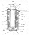
- FIG. 7 is a cross-sectional view illustrating a schematic configuration of hydrogen generation apparatus 101 of the related art which is disclosed in PTL 1.
- hydrogen generation apparatus 101 of the related art which is disclosed in PTL 1, is provided with cylindrical combustion tube 130 below heating unit 102 that combusts fuel.
- Bottomed cylindrical inner tube 105 which includes inner tube bottom plate 106, is disposed on an outer side of combustion tube 130.
- Bottomed intermediate tube 107 which includes intermediate tube bottom plate 108, is disposed on an outer side of inner tube 105.
- Bottomed cylindrical outer tube 115 which includes outer tube bottom plate 116, is disposed on an outer side of intermediate tube 107.
- Combustion tube 130, inner tube 105, intermediate tube 107, and outer tube 115 are disposed in a substantially concentric circular shape (including a concentric circular shape) when seen in a plan view (when seen from an upper surface). Upper portions of inner tube 105, intermediate tube 107, and outer tube 115 are appropriately connected to each other to constitute a reactor having a substantially cylindrical shape (including a cylindrical shape).
- Through-hole 109 is formed in a central portion of intermediate tube bottom plate 108.
- Intermediate tube 107 forms a gas flow path (first gas flow path), which folds back in an opposite direction (in FIG. 7 , from a lower side to an upper side) partway through the gas flow path (at through-hole 109 in intermediate tube bottom plate 108), by using a space between intermediate tube 107 and inner tube 105, and a space between intermediate tube 107 and outer tube 115.
- raw material supply unit 104 which is connected to an external gas pipeline and supplies a raw material gas to hydrogen generation apparatus 101 (specifically, the space between inner tube 105 and intermediate tube 107), is provided to an external wall surface of hydrogen generation apparatus 101 on a side (in FIG. 7 , an upper side) that is opposite to a gas folding-back portion (in FIG. 7 , a lower side).
- water supply unit 103 which is connected to an external water pipeline and supplies water to hydrogen generation apparatus 101 (specifically, the space between inner tube 105 and intermediate tube 107), is provided to an outer wall surface of hydrogen generation apparatus 101 on an upper side in FIG. 7 .
- a flowing direction of the reformed gas in through-hole 109 is reversed, and the reformed gas flows between intermediate tube 107 and outer tube 115 toward discharge portion 112, and passes through modification section 125 and selective oxidation section 126. According to this, carbon monoxide in the reformed gas is reduced.
- Preheating unit 123 is provided in the space between inner tube 105 and intermediate tube 107.
- water that is supplied from water supply unit 103 is evaporated and a mixed gas of a raw material gas and water vapor is preheated by using heat that is transferred from a combustion exhaust gas of heating unit 102, which passes through a space between combustion tube 130 and inner tube 105, through inner tube 105.
- the raw material gas and the water vapor are subjected to a reforming reaction with a reforming catalyst by using heat that is transferred from the combustion exhaust gas of heating unit 102, which passes through the space between combustion tube 130 and inner tube 105, through inner tube 105 to generate a reformed gas.
- Selective oxidation section 126 which is provided on a downstream side (upper side) of modification section 125 in the space between intermediate tube 107 and outer tube 115, converts carbon monoxide, which remains in a hydrogen-containing gas after the water gas shift reaction in modification section 125, into carbon dioxide with a selective oxidation catalyst by using air that is supplied from air supply unit 119 to a hydrogen-containing gas after passing through modification section 125.
- Reforming catalyst section 120 is provided with an Ru-based reforming catalyst in a spherical shape having a diameter of approximately 3 mm. Specifically, in a space that is constituted by lateral surfaces of inner tube 105 and intermediate tube 107, the reforming catalyst is provided on a tray that is constituted by a punching metal, which has a diameter smaller than the size of the reforming catalyst, that is, a bore diameter of approximately 2 mm, on a lateral surface portion of intermediate tube 107.
- modification section 125 is provided with a Cu-Zn-based CO modification catalyst in a cylindrical shape having a diameter of approximately 3 mm and a height of 3 mm.
- selective oxidation section 126 is provided with an Ru-based selective oxidation catalyst in a spherical shape having a diameter of approximately 3 mm.
- a side, from which the raw material gas flows into reforming catalyst section 120, is set as an upstream, and a side, from which the reformed gas flows out, is set as a downstream.
- a downstream portion of reforming catalyst section 120 is set as reforming catalyst downstream portion 120a.
- Heating unit 102 is configured to supply reaction heat necessary for a reforming reaction in reforming catalyst section 120, on an inner side of inner tube 105.
- Heating unit 102 includes a burner that combusts a combustion gas that becomes a heating source, combustion detector 122 including a flame rod that detects a combustion state of heating unit 102, and combustion fan 118 as a combustion air supply unit that supplies combustion air to heating unit 102.
- the flame rod is a device that applies a voltage to an ion that is generated when a flame is formed, and measures an ion current value that flows at that time.
- a combustion gas to be combusted in heating unit 102 is supplied to heating unit 102 through a combustion gas supply path.
- a hydrogen-containing gas that is generated by hydrogen generation apparatus 101 is supplied to a fuel cell and the like which are provided on an outer side through discharge portion 112.
- reforming catalyst section 120 and preheating unit 123 have a configuration in which heat is supplied thereto from the combustion exhaust gas that is generated in heating unit 102 through a wall surface of inner tube 105 that faces combustion tube 130 of heating unit 102.
- the combustion exhaust gas passes through the inside (inner side) of combustion tube 130 from heating unit 102, gets out of combustion tube 130, and comes into contact with a lower portion of inner tube 105 and inner tube bottom plate 106 in a high-temperature state.
- the combustion exhaust gas passes through a passage that is constituted by an outer peripheral surface of combustion tube 130 and an inner peripheral surface of inner tube 105, and is exhausted from a discharge port on an upper right side in the drawing to the outside of hydrogen generation apparatus 101.
- inner tube 105 and inner tube bottom plate 106 reach a high temperature due to heat of the combustion exhaust gas. Accordingly, there is a possibility that inner tube 105 and inner tube bottom plate 106 may be thermally deformed when being used for a long period of time. Particularly, in a portion that is not filled with a reforming catalyst, heat is not consumed through an endothermic reaction of the reforming catalyst, and thus a tendency of the thermal deformation becomes more significant.
- heat insulation material 140 is disposed on inner tube bottom plate 106 at a position that faces heating unit 102. According to this, it is possible to prevent a portion, which is not filled with the reforming catalyst, in inner tube bottom plate 106 and inner tube 105 from reaching a high temperature. Furthermore, SUS310S material, in which a proportion of nickel is great and which is strong against high-temperature thermal deformation, is used in inner tube bottom plate 106 and inner tube 105 for safety.
- hydrogen generation apparatus 101 is provided with a reforming temperature detector 121 that detects a temperature of a reforming catalyst in reforming catalyst section 120, and a modification temperature detector 124 that detects a temperature of a CO modification catalyst in modification section 125 so as to control an operation of hydrogen generation apparatus 101.
- heat insulation material 140 is disposed with respect to a portion that is not filled with a reforming catalyst at a downstream portion of reforming catalyst section 120. That is, heat insulation material 140, which is configured to suppress heat transfer to the downstream portion of reforming catalyst section 120, is not disposed. Accordingly, it is difficult to prevent the reforming catalyst from reaching a high temperature.
- a temperature necessary for a catalyst reaction and a threshold temperature for retention of durability of a metal that constitutes inner tube 105 are approximately equal to 600°C to 700°C.
- the invention has been made in consideration of the above-described problem, and an object thereof is to provide a hydrogen generation apparatus that is excellent in durability even when reducing the amount of a reforming catalyst.
- the heat transfer suppressing unit since the heat transfer suppressing unit is provided, it is possible to prevent a downstream portion including a downstream-side end of a reforming catalyst in a gas flow direction from being heated more than necessary due to heat transfer from a combustion exhaust gas. Accordingly, it is possible to realize a hydrogen generation apparatus in which a reduction in cost is attained by reducing the amount of an expensive reforming catalyst without the occurrence of a problem related to durability.
- FIG. 1 is a cross-sectional view illustrating a configuration of a main portion of hydrogen generation apparatus 1 according to the exemplary embodiment of the invention.
- hydrogen generation apparatus 1 is provided with cylindrical combustion tube 30 below heating unit 2 that is a combustor configured to combust fuel.
- Bottomed cylindrical inner tube 5 including inner tube bottom plate 6 is disposed on an outer side of cylindrical combustion tube 30.
- Bottomed cylindrical intermediate tube 7 including intermediate tube bottom plate 8 is disposed on an outer side of inner tube 5.
- Bottomed cylindrical outer tube 15 including outer tube bottom plate 16 is disposed on an outer side of intermediate tube 7.
- Combustion tube 30, inner tube 5, intermediate tube 7, and outer tube 15 are disposed in a substantially concentric shape (including a concentric shape) when seen in a plan view. Upper portions of inner tube 5, intermediate tube 7, and outer tube 15 are appropriately connected to each other to constitute a reactor having a substantially cylindrical shape (including a cylindrical shape).
- Through-hole 9 is formed in the central portion of intermediate tube bottom plate 8.
- Intermediate tube 7 forms a gas flow path (first gas flow path) which folds back in an opposite direction (in FIG. 1 , from a lower side to an upper side) partway through the gas flow path (at through-hole 9 of intermediate tube bottom plate 8) and which is formed by using a space between intermediate tube 7 and inner tube 5 and a space between intermediate tube 7 and outer tube 15.
- raw material supply unit 4 which is connected to an external gas pipeline and supplies a raw material gas to hydrogen generation apparatus 1 (the space between inner tube 5 and intermediate tube 7), is provided to an external wall surface of hydrogen generation apparatus 1 on a side (in FIG. 1 , an upper side) that is opposite to a gas folding-back portion side (in FIG. 1 , a lower side).
- water supply unit 3 which is connected to an external water pipeline and supplies water to hydrogen generation apparatus 1 (the space between inner tube 5 and intermediate tube 7), is provided to an outer wall surface of hydrogen generation apparatus 1.
- a flowing direction of the reformed gas in through-hole 9 is reversed, and the reformed gas flows between intermediate tube 7 and outer tube 15 toward discharge portion 12, and passes through modification section 25 and selective oxidation section 26. According to this, carbon monoxide in the reformed gas is reduced.
- preheating unit 23 that is provided in the space between inner tube 5 and intermediate tube 7, water that is supplied from water supply unit 3 is evaporated and a mixed gas of a raw material gas and water vapor is preheated by using heat that is transferred from a combustion exhaust gas (heated gas) of heating unit 2, which passes through a space between combustion tube 30 and inner tube 5, through inner tube 5.
- Reforming catalyst section 20 is provided in the space between inner tube 5 and intermediate tube 7 on a downstream side (lower side) of preheating unit 23.
- heat which is transferred from the combustion exhaust gas (heated gas) of heating unit 2 through inner tube 5, is used.
- the combustion exhaust gas passes through the space between combustion tube 30 and inner tube 5.
- a raw material gas and water vapor are subjected to a reforming reaction with a reforming catalyst to generate a reformed gas.
- Selective oxidation section 26 is provided in the space between intermediate tube 7 and outer tube 15 on a downstream side (upper side) of modification section 25.
- carbon monoxide which remains in a hydrogen-containing gas after the water gas shift reaction in modification section 25, can be converted into carbon dioxide with a selective oxidation catalyst by using air that is supplied from air supply unit 19 to a hydrogen-containing gas after passing through modification section 25.
- Reforming catalyst section 20 is provided with an Ru-based reforming catalyst in a spherical shape having a diameter of approximately 3 mm. Specifically, in a space that is constituted by lateral surfaces of inner tube 5 and intermediate tube 7, the reforming catalyst is provided on a tray that is constituted by a punching metal, which has a diameter smaller than the size of the reforming catalyst, that is, a bore diameter of approximately 2 mm, on a lateral surface portion of intermediate tube 7.
- modification section 25 is provided with a Cu-Zn-based CO modification catalyst in a cylindrical shape having a diameter of approximately 3 mm and a height of 3 mm.
- selective oxidation section 26 is provided with an Ru-based selective oxidation catalyst in a spherical shape having a diameter of approximately 3 mm.
- a side, into which the reformed gas flows, is set as an upstream, and a side, from which the reformed gas flows out, is set as a downstream.
- a downstream portion, from which the reformed gas flows out is set as reforming catalyst downstream portion 20a.
- Hydrogen generation apparatus 1 is provided with heating unit 2, which is configured to supply reaction heat necessary for a reforming reaction in reforming catalyst section 20, on an inner side of inner tube 5.
- heating unit 2 is configured to supply reaction heat necessary for a reforming reaction in reforming catalyst section 20, on an inner side of inner tube 5.
- description has been made by using a combustor as an example of heating unit 2, but the heating unit of the invention is not limited thereto.
- heating unit 2 may be an electric heater.
- Heating unit 2 includes a burner that combusts a combustion gas that becomes a heating source, a combustion detector including a flame rod that detects a combustion state of heating unit 2, and combustion fan 18 as a combustion air supply unit that supplies combustion air to heating unit 2. Furthermore, the flame rod is a device that applies a voltage to an ion that is generated when a flame is formed, and measures an ion current value that flows at that time.
- a combustion gas to be combusted in heating unit 2 is supplied to heating unit 2 through a combustion gas supply path.
- a hydrogen-containing gas that is generated by hydrogen generation apparatus 1 is supplied to a fuel cell and the like which are provided on an outer side through discharge portion 12.
- Reforming catalyst section 20 and preheating unit 23 have a configuration in which heat is supplied thereto from the combustion exhaust gas that is generated in heating unit 2 through a wall surface of inner tube 5 that faces combustion tube 30 of heating unit 2.
- the combustion exhaust gas passes through the inside (inner side) of combustion tube 30 from heating unit 2, gets out of combustion tube 30, and comes into contact with a lower portion of inner tube 5 and inner tube bottom plate 6 in a high-temperature state.
- the combustion exhaust gas passes through a passage that is constituted by an outer peripheral surface of combustion tube 30 and an inner peripheral surface of inner tube 5, and is exhausted from a discharge port on an upper right side in the drawing to the outside of hydrogen generation apparatus 1.
- a temperature of reforming catalyst downstream portion 20a is adjusted to a first temperature (for example, 600°C) so that a conversion ratio of a reformed gas at an outlet of reforming catalyst section 20 becomes a predetermined first conversion ratio (for example, 85%).
- the upper limit of the conversion ratio is determined in accordance with a catalyst temperature, and when the temperature is high, the upper limit tends to rise.
- the temperature of reforming catalyst downstream portion 20a so as to set the conversion ratio to the first conversion ratio is determined as the first temperature, and thus it is possible to avoid a problem such as deformation by appropriately selecting a material of inner tube 5 and inner tube bottom plate 6.
- the conversion ratio at the outlet of reforming catalyst section 20 becomes a value that is lower than the conversion ratio upper limit at a corresponding temperature (details thereof will be described later). According to this, in a case where the conversion ratio at the outlet of reforming catalyst section 20 is retained to the first conversion ratio, the temperature of reforming catalyst downstream portion 20a excessively rises. As a result, inner tube 5 and inner tube bottom plate 6 at the periphery of reforming catalyst downstream portion 20a tend to be thermally deformed.
- FIG. 2A is a view illustrating temperature variation characteristics of reforming catalyst section 120, in which a reforming catalyst is heated by heat transfer from a combustion exhaust gas over the entire region from an upstream portion to a downstream portion thereof, in a raw material gas flow direction in hydrogen generation apparatus 101 of the comparative example.
- FIG. 2B is a view illustrating variation characteristics of a conversion ratio (value indicating that a raw material gas is converted to hydrogen to a certain extent) of a gas, which is passing through reforming catalyst section 120 in which the reforming catalyst is heated by heat transfer from the combustion exhaust gas over the entire region from an upstream portion to a downstream portion thereof, in a gas flow direction in hydrogen generation apparatus 101 of the comparative example.
- a conversion ratio value indicating that a raw material gas is converted to hydrogen to a certain extent
- the temperature of the reforming catalyst that is heated has a temperature distribution in which the temperature gradually rises from an inlet portion into which the raw material gas flows toward an outlet portion from which a reformed gas generated through a reforming reaction flows out.
- a conversion ratio of a gas, which is passing through reforming catalyst section 120 has characteristics in which the upper limit of the conversion ratio increases as the temperature rises. Accordingly, so as to generate hydrogen gas in an amount that is required by a fuel cell system, an operation of hydrogen generation apparatus 101 is performed after adjusting a temperature at the outlet of reforming catalyst section 120 to a first temperature (for example, 600°C) so that the conversion ratio of the reformed gas that flows out from reforming catalyst section 120 becomes a first conversion ratio (for example, 85%) that is necessary.
- a first temperature for example, 600°C
- a reaction progress rate in reforming catalyst section 120 is sufficiently faster than a flow rate of the gas that passes therethrough, and thus the conversion ratio of the reformed gas, which flows out from reforming catalyst section 120, is set to be approximately the same as the upper limit with respect to an approximate temperature (as illustrated in FIG. 2B , a difference from the upper limit hardly occurs).
- the amount of the reforming catalyst is reduced.
- the temperature of reforming catalyst section 120 deviates in a high-temperature direction.
- FIG. 3A is a view illustrating the temperature variation characteristics of reforming catalyst section 120 in the raw material gas flow direction in hydrogen generation apparatus 101 of the comparative example in a case where the amount of the reforming catalyst is reduced by half.
- FIG. 3B is a view illustrating variation characteristics in a conversion ratio of a gas, which is passing through reforming catalyst section 120, in a gas flow direction in hydrogen generation apparatus 101 of the comparative example in a case where the amount of the reforming catalyst is reduced by half.
- a first conversion ratio and a first temperature in FIG. 3A and FIG. 3B indicate the same values as the first conversion ratio and the first temperature in FIG. 2A and FIG. 2B .
- the conversion ratio of a passing gas does not reach the upper limit of the conversion ratio with respect to a temperature of each portion, and it enters a state in which a reaction is not completed (according to this, as indicated by an arrow D on a right end in FIG. 3B , it is necessary to further raise the conversion ratio upper limit so as to retain the conversion ratio of the reformed gas that flows out).
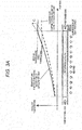
- FIG. 4A is a view illustrating temperature variation characteristics of reforming catalyst section 20 in a raw material gas flow direction in hydrogen generation apparatus 1 according to an exemplary embodiment of the invention.
- FIG. 4B is a view illustrating variation characteristics of a conversion ratio of a gas, which is passing through reforming catalyst section 20, in a gas flow direction in hydrogen generation apparatus 1.
- a first temperature and a first conversion ratio in FIG. 4A and FIG. 4B indicate the same values as the first temperature and the first conversion ratio in FIG. 2A , FIG. 2B , FIG. 3A , and FIG. 3B .
- heat insulation material 40 as the heat transfer suppressing unit is also disposed at a position (refer to region C in FIG. 1 ), which faces reforming catalyst downstream portion 20a including a lower end of reforming catalyst section 20, on a surface of inner tube 5 on heating unit 2 (combustion tube 30) side in addition to a surface of inner tube bottom plate 6 on heating unit 2 (combustion tube 30) side and a surface of inner tube 5 on heating unit 2 (combustion tube 30) side downstream (on a lower side) of the lower end of reforming catalyst section 20.
- Heat insulation material 40 is composed of ceramic fiber and can endure a temperature of 1,000°C or lower. According to this, it is possible to suppress a temperature rise toward an outlet of reforming catalyst section 20 to be low from the viewpoint of suppression of heat transfer from the combustion exhaust gas.
- the length of reforming catalyst downstream portion 20a, which is protected by the heat transfer suppressing unit is not limited, and may be appropriately set in accordance with a target temperature gradient in a catalyst temperature, a material and the thickness of heat insulation material 40, and the like.
- heat insulation material 40 is disposed as much as possible at a portion that faces reforming catalyst section 20, it is possible to exhibit a heat transfer suppressing effect.
- region B which is constant at approximately the first temperature, in the vicinity of reforming catalyst downstream portion 20a.
- a conversion ratio of a passing gas does not reach the first conversion ratio (refer to FIG. 4B ).
- region B a constant-temperature region
- a reforming reaction progresses, and thus the conversion ratio of the reformed gas reaches the first conversion ratio at a point of time at which the reformed gas flows out from the outlet of reforming catalyst section 20 (refer to FIG. 4B ).
- the amount of a hydrogen gas in a hydrogen-containing gas, which is transmitted from hydrogen generation apparatus 1 can be retained in the same amount as in the related art.
- the heat transfer suppressing unit is disposed, and thus a region (region B), in which the catalyst temperature is retained at a constant temperature after the catalyst temperature is raised to a predetermined first temperature (point A), is provided.
- the invention is not limited to this example.
- the invention also includes a configuration in which a heat transfer suppressing unit is disposed to make a temperature gradient on an outlet side of the reformed gas smaller (that is, duller) than a temperature gradient on an inlet side of the raw material gas.
- hydrogen generation apparatus 1 of this exemplary embodiment includes heating unit 2.
- the reforming catalyst is disposed in reforming catalyst section 20, and the raw material gas flows into reforming catalyst section 20 (the reforming catalyst therein).
- hydrogen generation apparatus 1 is provided with inner tube 5 that functions as a wall that partitions a first gas flow path through which the reformed gas from reforming catalyst section 20 (reforming catalyst therein) flows out, and an exhaust gas flow path (second gas flow path) through which a combustion exhaust gas (heated gas) generated due to heating by heating unit 2 flows.
- Hydrogen generation apparatus 1 heats the reforming catalyst in reforming catalyst section 20 by using heat, which is transferred through inner tube 5, of the combustion exhaust gas.
- hydrogen generation apparatus 1 is provided with the heat transfer suppressing unit (heat insulation material 40 that is provided on a surface of inner tube 5 on a heated gas side which faces at least a position of reforming catalyst downstream portion 20a) that suppresses heat transfer from the heated gas to the downstream portion (reforming catalyst downstream portion 20a) including the downstream-side end in a flow direction of the reformed gas in reforming catalyst section 20.
- the heat transfer suppressing unit heat insulation material 40 that is provided on a surface of inner tube 5 on a heated gas side which faces at least a position of reforming catalyst downstream portion 20a
- the conversion ratio at the outlet of reforming catalyst section 20 is approximately equal to the upper limit of the conversion ratio with respect to a temperature of the outlet (refer to FIG. 4B ).
- hydrogen generation apparatus 1 includes reforming temperature detector 21 that detects a temperature of the reforming catalyst in reforming catalyst section 20 to control an operation, and modification temperature detector 24 that detects a temperature of a CO modification catalyst in modification section 25.
- a conversion ratio in reforming catalyst downstream portion 20a is approximately equal to the upper limit of a conversion ratio with respect to a temperature of reforming catalyst downstream portion 20a, and thus it is possible to estimate the amount of the hydrogen gas with high accuracy through the temperature detection. As a result, it is possible to control the entirety of a fuel cell system with high accuracy.
- combustion exhaust gas blocking unit 41 which forms space 41a between an exhaust gas flow path (second gas flow path) and a gas flow path (first gas flow path) of reforming catalyst downstream portion 20a, may be provided instead of disposing heat insulation material 40.
- FIG. 5 is a view illustrating an additional configuration of hydrogen generation apparatus 1 according to the exemplary embodiment of the invention.
- Combustion exhaust gas blocking unit 41 illustrated in FIG. 5 has a configuration that is connected to inner tube 5 on an upper side (upstream) of reforming catalyst downstream portion 20a to close a lower opening of inner tube 5 instead of inner tube bottom plate 6 that is connected to a lower end of inner tube 5 to close the lower opening of inner tube 5.
- the heat transfer suppressing unit of the invention is not limited to this example, and space 41a may be formed, for example, by providing hollow cylindrical combustion exhaust gas blocking unit 41 in addition to inner tube bottom plate 6.
- reforming catalyst downstream portion 20a is not directly heated by the combustion exhaust gas, and thus it is possible to suppress heat transfer from the combustion exhaust gas to reforming catalyst downstream portion 20a.
- preheating unit 23 is provided to share a single-side wall surface (intermediate tube 8) with discharge portion 12, and a carbon monoxide reducing section (selective oxidation section 26 and modification section 25).
- Preheating unit 23 has a configuration capable of performing heat exchange with a hydrogen-containing gas that flows through discharge portion 12 and the carbon monoxide reducing section, and a catalyst that is provided in selective oxidation section 26 and modification section 25.
- a raw material gas which is supplied from raw material supply unit 4, may be a raw material gas including an organic compound such as hydrocarbon that contains at least carbon and hydrogen elements.
- a raw material gas including an organic compound such as hydrocarbon that contains at least carbon and hydrogen elements.
- city gas and natural gas which include methane as a main component, LPG, and the like can be used as the raw material gas.
- a gas infrastructure line of the city gas is used as a supply source of the raw material gas, and a desulfurizing unit, which removes a sulfur compound that is an odorization component in the raw material gas, is connected to the gas infrastructure line.
- a desulfurizing unit which removes a sulfur compound that is an odorization component in the raw material gas
- a desulfurizing unit which removes a sulfur compound that is an odorization component in the raw material gas
- a buster pump can be used as water supply unit 3 and raw material supply unit 4.
- the buster pump has a function of adjusting a flow rate of water that is supplied, and a flow rate of the raw material gas by controlling an input current pulse, an input power, and the like.
- a microporous-based heat insulation material for example, a heat insulation material that is a material having low heat conductivity such as WDS and Microtherm (product names) (registered trademarks) is provided to come into close contact with outer tube 15 and outer tube bottom plate 16.
- FIG. 6 is a view illustrating a schematic configuration of hydrogen generation apparatus 91 according to the example.
- hydrogen generation apparatus 91 of this example is constituted by a plurality of containers having a flat plate shape.
- Hydrogen generation apparatus 91 includes at least reforming section container 51, preheating unit container 52, combustion container 53, modification section 25, and selective oxidation section 26.
- Hydrogen generation apparatus 91 of this example includes preheating unit 23 that evaporates water supplied from water supply unit 3 and preheats a mixed gas of a raw material gas and water vapor.
- hydrogen generation apparatus 91 includes reforming catalyst section 20 that allows a reforming reaction of the raw material gas supplied from raw material supply unit 4 and water vapor to progress, and modification section 25 that subjects carbon monoxide and water vapor in a reformed gas generated in reforming catalyst section 20 to a modification reaction (shift reaction) so as to reduce the concentration of carbon monoxide in the reformed gas.
- hydrogen generation apparatus 91 includes selective oxidation section 26 that removes carbon monoxide, which remains in a hydrogen-containing gas after passing through modification section 25, mainly through oxidation by using air that is supplied from air supply unit 19 to the hydrogen-containing gas after passing through modification section 25.
- carbon monoxide reducing section is constituted by modification section 25 and selective oxidation section 26.
- Reforming catalyst section 20 is provided with an Ru-based reforming catalyst in a spherical shape having a diameter of approximately 3 mm.
- modification section 25 is provided with a Cu-Zn-based CO modification catalyst in a cylindrical shape having a diameter of approximately 3 mm and a height of 3 mm
- selective oxidation section 26 is provided with an Ru-based selective oxidation catalyst having a spherical shape having a diameter of approximately 3 mm.
- a side (a lower side in FIG. 6 ), from which a reformed gas flows into reforming catalyst section 20, is set as an upstream, and a side (an upper side in FIG. 6 ), from which a reformed gas flows out, is set as a downstream.
- a downstream portion, from which the reformed gas flows out, of reforming catalyst section 20 is set as reforming catalyst downstream portion 20a.
- hydrogen generation apparatus 1 is provided with heating unit 2, which supplies reaction heat necessary for a reforming reaction in reforming catalyst section 20, on an upper side of combustion container 53.
- Heating unit 2 is a combustor including a burner that combusts a combustion gas as a heating source. Fuel air is supplied to heating unit 2 from combustion fan 18 as a combustion air supply unit, and fuel is supplied to heating unit 2 from fuel supply unit 17.
- a hydrogen-containing gas which is generated by hydrogen generation apparatus 91 having the above-described configuration, is supplied from discharge portion 12 to a fuel cell and the like which are provided on an outer side and is used for power generation in the fuel cell.
- Heat of a combustion exhaust gas which is a heated gas generated in heating unit 2, is supplied to reforming catalyst section 20 of hydrogen generation apparatus 91 through a wall surface at which reforming section container 51 and combustion container 53 come into contact with each other.
- the combustion exhaust gas comes into contact with an inner surface of combustion container 53 in a high-temperature state from heating unit 2, flows out from combustion container 53, and is additionally introduced into preheating unit container 52.
- the combustion exhaust gas supplies heat to water and a mixed gas of a raw material gas and water vapor through preheating unit heat transfer wall 231, the water and the mixing gas flowing through preheating unit 23.
- the combustion exhaust gas is exhausted from combustion exhaust gas output 232 on an upper side of preheating unit container 52 to an outer side of hydrogen generation apparatus 91.
- heat insulation material 140 is provided on a side of combustion container 53 which is opposite to reforming section container 51, and does not function as the heat transfer suppressing unit.
- the combustion exhaust gas comes into contact with the inner surface of combustion container 53 in a high-temperature state (850°C to 950°C), and heats reforming catalyst section 20 through the wall surface at which reforming section container 51 and combustion container 53 come into contact with each other.
- a temperature of reforming catalyst downstream portion 20a may excessively rise due to the same reason as in the exemplary embodiment.
- reforming section container 51 and combustion container 53 in the vicinity of reforming catalyst downstream portion 20a tend to be thermally deformed.
- reforming section container 51 When reforming section container 51 is thermally deformed, a metal that constitutes reforming section container 51 is destroyed. Therefore, there is a possibility that a reformed gas on a side, at which a pressure is higher than the atmosphere, may be leaked to the outside of a path with reforming section container 51 set as a boundary. In addition, at this time, there is a possibility that a flow rate of the hydrogen-containing gas that is supplied to the fuel cell becomes deficient, and thus the fuel cell system is stopped.
- combustion exhaust gas blocking unit 41 which is a groove-shaped concave portion, is provided to a portion of combustion container 53 which faces reforming catalyst downstream portion 20a. Specifically, heat transfer from the combustion exhaust gas to reforming catalyst downstream portion 20a is suppressed due to space 41a that is formed by combustion exhaust gas blocking unit 41 that is provided between combustion exhaust gas blocking unit 41 and reforming section container 51. According to this, it is possible to suppress a temperature rise toward an outlet of reforming catalyst section 20 to be low. Furthermore, heat insulation material 40 may be provided at a position of space 41a, and heat insulation material 40 may be provided instead of space 41a. In addition, space 41a may have any shape as long as a configuration, in which the combustion exhaust gas does not come into contact with inner tube 5 in the vicinity of reforming catalyst downstream portion 20a, can be realized.
- region B which is constant at approximately the first temperature, in the vicinity of reforming catalyst downstream portion 20a.
- a conversion ratio of a passing gas does not reach the first conversion ratio (for example, 85% of the upper limit of the conversion ratio with respect to a temperature) (refer to FIG. 4B ).
- FIG. 4B illustrates the first conversion ratio
- a water supply path is connected to water supply unit 3.
- a raw material supply path is connected to raw material supply unit 4.
- a raw material gas, which is supplied from raw material supply unit 4 may be a raw material gas including an organic compound such as hydrocarbon that contains at least carbon and hydrogen elements.
- an organic compound such as hydrocarbon that contains at least carbon and hydrogen elements.
- city gas and natural gas which include methane as a main component, LPG, and the like can be used as the raw material gas.
- a gas infrastructure line of the city gas is used as a supply source of the raw material gas, and a desulfurizing unit, which removes a sulfur compound that is an odorization component in the raw material gas, is connected to the gas infrastructure line.
- a desulfurizing unit which removes a sulfur compound that is an odorization component in the raw material gas
- a desulfurizing unit which removes a sulfur compound that is an odorization component in the raw material gas
- a buster pump can be used as water supply unit 3 and raw material supply unit 4.
- the buster pump has a function of adjusting a flow rate of water that is supplied, and a flow rate of the raw material gas by controlling an input current pulse, an input power, and the like.
- hydrogen generation apparatuses 1 and 91 of the exemplary embodiment and example include heating unit 2, the first gas flow path in which reforming catalyst section 20 is disposed, and in which the raw material gas flows into reforming catalyst section 20 and the reformed gas flows out from reforming catalyst section 20, and the second gas flow path through which a heated gas heated by heating unit 2 flows.
- hydrogen generation apparatuses 1 and 91 have a wall that partitions the first gas flow path and the second gas flow path, and have a configuration in which reforming catalyst section 20 is heated by using heat, which is transferred through the wall, of the heated gas.
- hydrogen generation apparatuses 1 and 91 include the heat transfer suppressing unit that suppresses heat transfer from the heated gas to reforming catalyst downstream portion 20a including a downstream-side end of reforming catalyst section 20 in a flow direction of the reformed gas.
- the heat transfer suppressing unit may be constituted by heat insulation material 40 that is provided on a surface of the wall on a heated gas side.
- the heat transfer suppressing unit may be constituted by a space that is formed by a combustion exhaust gas blocking unit that is disposed between the second gas flow path and the first gas flow path downstream of the reforming catalyst section.
- heating unit 2 is a combustor
- the heated gas is the combustion exhaust gas that is generated through combustion in the combustor.
- the invention can exhibit a remarkable effect in which durability is excellent even when reducing the amount of the reforming catalyst. Accordingly, the invention is useful as a hydrogen generation apparatus that generates a hydrogen-containing gas through a reforming reaction of a raw material gas and water vapor by using a reforming catalyst, and the like.
Landscapes
- Chemical & Material Sciences (AREA)
- Chemical Kinetics & Catalysis (AREA)
- Organic Chemistry (AREA)
- Health & Medical Sciences (AREA)
- General Health & Medical Sciences (AREA)
- Engineering & Computer Science (AREA)
- Combustion & Propulsion (AREA)
- Inorganic Chemistry (AREA)
- Physics & Mathematics (AREA)
- Fluid Mechanics (AREA)
- Hydrogen, Water And Hydrids (AREA)
Claims (3)
- Wasserstofferzeugungs-Vorrichtung, die umfasst:eine Heiz-Einheit (2);eine Wasserzufuhr-Einheit (3), die an einer Außenwandfläche der Wasserstofferzeugungs-Vorrichtung (1) vorhanden ist;eine zylindrische Brennröhre (30), die unterhalb der Heiz-Einheit (2) vorhanden ist;eine innere Röhre (5), die eine Bodenplatte (6) der inneren Röhre einschließt und an einer Außenseite der Brennröhre (30) angeordnet ist;eine Zwischen-Röhre (7), die an einer Außenseite der inneren Röhre (5) angeordnet ist, wobei die Zwischen-Röhre (7) eine Zwischen-Bodenplatte (8) einschließt;ein Durchgangsloch (9), das in dem Mittelabschnitt der Bodenplatte (8) der Zwischen-Röhre ausgebildet ist;eine äußere Röhre (15), die an einer Außenseite der Zwischen-Röhre (7) angeordnet ist, wobei die äußere Röhre (15) eine Bodenplatte (16) der äußeren Röhre einschließt;wobei Brennröhre (30), innere Röhre (5), Zwischen-Röhre (7) und äußere Röhre (15) in einer im Wesentlichen konzentrischen Form angeordnet sind;einen Reformierkatalysator-Abschnitt (20), an dem ein von einer Rohstoffzufuhr-Einheit (4) zugeführtes Rohstoff-Gas und von einer Wasserzufuhr-Einheit (3) zugeführtes Wasser zu einem reformierten Gas reformiert werden, zwischen der inneren Röhre (5) und der Zwischen-Röhre (7) vorhanden ist;einen ersten Gas-Strömungsweg, in dem das Rohstoff-Gas, das einem Raum zwischen der inneren Röhre (5) und der Zwischen-Röhre (7) zugeführt wird, von einer oberen Seite des Reformierkatalysator-Abschnitts (20) in den Reformierkatalysator-Abschnitt (20) einströmt, und das reformierte Gas, das über ein unteres Ende des Reformierkatalysator-Abschnitts (20) ausströmt, von einer unteren Seite teilweise über den ersten Gas-Strömungsweg zu einer oberen Seite zurückströmt und zu einer Außenseite der Wasserstofferzeugungs-Vorrichtung (1, 91) durch einen Raum zwischen der Zwischen-Röhre (7) und der äußeren Röhre (15) ausströmt;einen zweiten Gas-Strömungsweg, in dem ein erhitztes Gas, das von der Heiz-Einheit (2) in einen Innenraum der Brennröhre (30) abgeleitet wird, aus der Brennröhre (30) austritt und durch einen Raum zwischen der Brennröhre (30) und der inneren Röhre (5) strömt,wobei der Reformierkatalysator-Abschnitt (20) unter Verwendung von Wärme des erhitzten Gases erhitzt wird, die über die innere Röhre (5) übertragen wird,eine Einheit (40) zum Einschränken von Wärmeübertragung;eine Ableitöffnung (12);eine Vorheiz-Einheit (23), die in dem Raum zwischen der inneren Röhre (5) und der Zwischen-Röhre (7) vorhanden ist;einen Modifizierungs-Teilabschnitt (25), der in dem Raum zwischen der Zwischen-Röhre (7) und der äußeren Röhre (15) vorhanden ist, wobei der Modifizierungs-Teilabschnitt (25) so ausgeführt ist, dass er Kohlenmonoxid in dem reformierten Gas, das an dem Reformierkatalysator-Abschnitt (20) erzeugt wird, unter Einsatz eines CO-Modifizierungskatalysators zur Umwandlung in Kohlendioxid einer Wassergas-Shift-Reaktion mit Wasserdampf unterzieht;einen Teilabschnitt (26) für selektive Oxidation, der in dem Raum zwischen der Zwischen-Röhre (7) und der äußeren Röhre (15) an einer stromab liegenden Seite des Modifizierungs-Teilabschnitts (25) vorhanden ist, wobei der Teilabschnitt (26) für selektive Oxidation so ausgeführt ist, dass er Kohlenmonoxid, das in einem wasserstoffhaltigen Gas nach der Wassergas-Shift-Reaktion in dem Modifizierungs-Teilabschnitt (25) verbleibt, mit einem selektiven Oxidationskatalysator unter Verwendung von Luft, die von einer Luftzufuhr-Einheit (19) einem wasserstoffhaltigen Gas zugeführt wird, nachdem es den Modifizierungs-Teilabschnitt (25) passiert hat, in Kohlendioxid umwandelt; sowieeine Rohstoffzufuhr-Einheit (4), die an einer Außenwandfläche der Wasserstofferzeugungs-Vorrichtung (1) an einer Seite vorhanden ist, die einer Seite eines Gas-Rücklaufabschnitts gegenüberliegt;dadurch gekennzeichnet, dassdie Einheit (40) zum Einschränken von Wärmeübertragung vorhanden ist, um Wärmeübertragung von dem erhitzten Gas auf einen stromab liegenden Abschnitt (20a) des Reformierkatalysators einzuschränken, der ein Abschnitt ist, der ein Ende des Reformierkatalysator-Abschnitts (20) an der stromab liegenden Seite in einer Strömungsrichtung des reformierten Gases, eine Fläche der Bodenplatte (6) der inneren Röhre an einer Seite der Heiz-Einheit sowie eine Fläche der inneren Röhre (5) an der Seite der Heiz-Einheit stromab von einem unteren Ende des Reformierkatalysator-Abschnitts (20) einschließt.
- Wasserstoff-Erzeugungsvorrichtung nach Anspruch 1,
wobei die Einheit (40) zum Einschränken von Wärmeübertragung ein Wärmeisoliermaterial (40) ist, das an einer Fläche der inneren Röhre (5) an der Seite des erhitzten Gases vorhanden ist. - Wasserstoff-Erzeugungsvorrichtung nach Anspruch 1 oder 2,
wobei die Heiz-Einheit (2) ein Brenner ist, und
das erhitzte Gas ein Verbrennungsabgas ist, das durch Verbrennung in dem Brenner entsteht.
Applications Claiming Priority (2)
| Application Number | Priority Date | Filing Date | Title |
|---|---|---|---|
| JP2014012960 | 2014-01-28 | ||
| PCT/JP2015/000276 WO2015115071A1 (ja) | 2014-01-28 | 2015-01-22 | 水素生成装置 |
Publications (3)
| Publication Number | Publication Date |
|---|---|
| EP3100976A1 EP3100976A1 (de) | 2016-12-07 |
| EP3100976A4 EP3100976A4 (de) | 2016-12-28 |
| EP3100976B1 true EP3100976B1 (de) | 2021-05-26 |
Family
ID=53756656
Family Applications (1)
| Application Number | Title | Priority Date | Filing Date |
|---|---|---|---|
| EP15742812.9A Active EP3100976B1 (de) | 2014-01-28 | 2015-01-22 | Wasserstoffgenerator |
Country Status (3)
| Country | Link |
|---|---|
| EP (1) | EP3100976B1 (de) |
| JP (1) | JP6467591B2 (de) |
| WO (1) | WO2015115071A1 (de) |
Families Citing this family (1)
| Publication number | Priority date | Publication date | Assignee | Title |
|---|---|---|---|---|
| JP7454764B2 (ja) * | 2021-01-14 | 2024-03-25 | パナソニックIpマネジメント株式会社 | 水素生成装置 |
Family Cites Families (8)
| Publication number | Priority date | Publication date | Assignee | Title |
|---|---|---|---|---|
| JPH0828202A (ja) * | 1994-07-12 | 1996-01-30 | Nissan Motor Co Ltd | 軸構造の組立方法 |
| JPH09249402A (ja) * | 1996-03-15 | 1997-09-22 | Mitsubishi Electric Corp | 改質装置 |
| JP4068111B2 (ja) * | 2004-02-17 | 2008-03-26 | 松下電器産業株式会社 | 水素生成装置およびこれを備えた燃料電池システム |
| JP2008120634A (ja) * | 2006-11-13 | 2008-05-29 | Idemitsu Kosan Co Ltd | 改質器、改質ユニットおよび燃料電池システム |
| JP2008192434A (ja) * | 2007-02-02 | 2008-08-21 | Idemitsu Kosan Co Ltd | 改質ユニットおよび燃料電池システム |
| JP2009249209A (ja) * | 2008-04-03 | 2009-10-29 | Panasonic Corp | 燃料処理装置 |
| JP2011102223A (ja) * | 2009-11-12 | 2011-05-26 | Panasonic Corp | 水素生成装置 |
| JP2011136865A (ja) * | 2009-12-28 | 2011-07-14 | Idemitsu Kosan Co Ltd | 改質装置、改質ユニットおよび燃料電池システム |
-
2015
- 2015-01-22 EP EP15742812.9A patent/EP3100976B1/de active Active
- 2015-01-22 JP JP2015559811A patent/JP6467591B2/ja active Active
- 2015-01-22 WO PCT/JP2015/000276 patent/WO2015115071A1/ja not_active Ceased
Non-Patent Citations (1)
| Title |
|---|
| None * |
Also Published As
| Publication number | Publication date |
|---|---|
| EP3100976A4 (de) | 2016-12-28 |
| WO2015115071A1 (ja) | 2015-08-06 |
| EP3100976A1 (de) | 2016-12-07 |
| JPWO2015115071A1 (ja) | 2017-03-23 |
| JP6467591B2 (ja) | 2019-02-13 |
Similar Documents
| Publication | Publication Date | Title |
|---|---|---|
| JP5164441B2 (ja) | 燃料電池システムの起動方法 | |
| JP5325403B2 (ja) | 燃料電池システムの起動方法 | |
| JP5214230B2 (ja) | 燃料電池システムの起動方法 | |
| US9012098B2 (en) | Hydrogen production apparatus and fuel cell system | |
| JP2009295380A (ja) | 間接内部改質型固体酸化物形燃料電池の停止方法 | |
| JP2015204172A (ja) | 燃料電池システム | |
| JP2009079155A (ja) | 液体燃料脱硫装置及び液体燃料脱硫システム | |
| EP3429008B1 (de) | Festoxid-brennstoffzelle | |
| EP2554512A1 (de) | Vorrichtung zur wasserstoffproduktion und brennstoffzellensystem | |
| JP5902581B2 (ja) | 燃料電池システム及びその制御方法 | |
| EP3100976A1 (de) | Wasserstoffgenerator | |
| EP3309887B1 (de) | Brennstoffzellensystem und verfahren zum betrieb des brennstoffzellensystems | |
| Meissner et al. | Start‐Up and Load‐Change Behavior of a Catalytic Burner for a Fuel‐Cell‐Based APU for Diesel Fuel | |
| JP2011102223A (ja) | 水素生成装置 | |
| JP5643707B2 (ja) | 水素含有ガス生成装置 | |
| JP2018104232A (ja) | 水素生成装置 | |
| JP5634729B2 (ja) | 水素製造装置及び燃料電池システム | |
| KR101350665B1 (ko) | 프록스 촉매 급속승온장치 및 이를 이용한 연료전지 시스템 운영 방법 | |
| JP2007331951A (ja) | 水素生成装置および燃料電池システム | |
| WO2011122373A1 (ja) | 水素製造装置、燃料電池システム及び水素製造装置の起動方法 | |
| JP2013234076A (ja) | 水素生成装置 | |
| WO2011027520A1 (ja) | 水素発生装置とその起動方法 | |
| JP4835273B2 (ja) | 水素生成装置および燃料電池システム | |
| JP2009289465A (ja) | 液体燃料脱硫器および液体燃料脱硫方法、並びに、燃料電池発電システム | |
| JP2009067645A (ja) | 水素製造装置及びこれを用いた燃料電池システム |
Legal Events
| Date | Code | Title | Description |
|---|---|---|---|
| PUAI | Public reference made under article 153(3) epc to a published international application that has entered the european phase |
Free format text: ORIGINAL CODE: 0009012 |
|
| STAA | Information on the status of an ep patent application or granted ep patent |
Free format text: STATUS: REQUEST FOR EXAMINATION WAS MADE |
|
| 17P | Request for examination filed |
Effective date: 20160629 |
|
| AK | Designated contracting states |
Kind code of ref document: A1 Designated state(s): AL AT BE BG CH CY CZ DE DK EE ES FI FR GB GR HR HU IE IS IT LI LT LU LV MC MK MT NL NO PL PT RO RS SE SI SK SM TR |
|
| AX | Request for extension of the european patent |
Extension state: BA ME |
|
| A4 | Supplementary search report drawn up and despatched |
Effective date: 20161130 |
|
| RIC1 | Information provided on ipc code assigned before grant |
Ipc: B01J 8/02 20060101ALN20161122BHEP Ipc: B01J 8/04 20060101ALN20161122BHEP Ipc: C01B 3/38 20060101AFI20161122BHEP |
|
| DAX | Request for extension of the european patent (deleted) | ||
| STAA | Information on the status of an ep patent application or granted ep patent |
Free format text: STATUS: EXAMINATION IS IN PROGRESS |
|
| 17Q | First examination report despatched |
Effective date: 20181024 |
|
| GRAP | Despatch of communication of intention to grant a patent |
Free format text: ORIGINAL CODE: EPIDOSNIGR1 |
|
| STAA | Information on the status of an ep patent application or granted ep patent |
Free format text: STATUS: GRANT OF PATENT IS INTENDED |
|
| RIC1 | Information provided on ipc code assigned before grant |
Ipc: B01J 8/04 20060101ALN20210122BHEP Ipc: C01B 3/38 20060101AFI20210122BHEP Ipc: B01J 8/02 20060101ALN20210122BHEP |
|
| INTG | Intention to grant announced |
Effective date: 20210208 |
|
| GRAS | Grant fee paid |
Free format text: ORIGINAL CODE: EPIDOSNIGR3 |
|
| GRAA | (expected) grant |
Free format text: ORIGINAL CODE: 0009210 |
|
| STAA | Information on the status of an ep patent application or granted ep patent |
Free format text: STATUS: THE PATENT HAS BEEN GRANTED |
|
| AK | Designated contracting states |
Kind code of ref document: B1 Designated state(s): AL AT BE BG CH CY CZ DE DK EE ES FI FR GB GR HR HU IE IS IT LI LT LU LV MC MK MT NL NO PL PT RO RS SE SI SK SM TR |
|
| REG | Reference to a national code |
Ref country code: GB Ref legal event code: FG4D |
|
| REG | Reference to a national code |
Ref country code: CH Ref legal event code: EP |
|
| REG | Reference to a national code |
Ref country code: AT Ref legal event code: REF Ref document number: 1396064 Country of ref document: AT Kind code of ref document: T Effective date: 20210615 |
|
| REG | Reference to a national code |
Ref country code: DE Ref legal event code: R096 Ref document number: 602015069711 Country of ref document: DE |
|
| REG | Reference to a national code |
Ref country code: IE Ref legal event code: FG4D |
|
| REG | Reference to a national code |
Ref country code: LT Ref legal event code: MG9D |
|
| REG | Reference to a national code |
Ref country code: AT Ref legal event code: MK05 Ref document number: 1396064 Country of ref document: AT Kind code of ref document: T Effective date: 20210526 |
|
| PG25 | Lapsed in a contracting state [announced via postgrant information from national office to epo] |
Ref country code: LT Free format text: LAPSE BECAUSE OF FAILURE TO SUBMIT A TRANSLATION OF THE DESCRIPTION OR TO PAY THE FEE WITHIN THE PRESCRIBED TIME-LIMIT Effective date: 20210526 Ref country code: FI Free format text: LAPSE BECAUSE OF FAILURE TO SUBMIT A TRANSLATION OF THE DESCRIPTION OR TO PAY THE FEE WITHIN THE PRESCRIBED TIME-LIMIT Effective date: 20210526 Ref country code: HR Free format text: LAPSE BECAUSE OF FAILURE TO SUBMIT A TRANSLATION OF THE DESCRIPTION OR TO PAY THE FEE WITHIN THE PRESCRIBED TIME-LIMIT Effective date: 20210526 Ref country code: AT Free format text: LAPSE BECAUSE OF FAILURE TO SUBMIT A TRANSLATION OF THE DESCRIPTION OR TO PAY THE FEE WITHIN THE PRESCRIBED TIME-LIMIT Effective date: 20210526 Ref country code: BG Free format text: LAPSE BECAUSE OF FAILURE TO SUBMIT A TRANSLATION OF THE DESCRIPTION OR TO PAY THE FEE WITHIN THE PRESCRIBED TIME-LIMIT Effective date: 20210826 |
|
| REG | Reference to a national code |
Ref country code: NL Ref legal event code: MP Effective date: 20210526 |
|
| PG25 | Lapsed in a contracting state [announced via postgrant information from national office to epo] |
Ref country code: GR Free format text: LAPSE BECAUSE OF FAILURE TO SUBMIT A TRANSLATION OF THE DESCRIPTION OR TO PAY THE FEE WITHIN THE PRESCRIBED TIME-LIMIT Effective date: 20210827 Ref country code: IS Free format text: LAPSE BECAUSE OF FAILURE TO SUBMIT A TRANSLATION OF THE DESCRIPTION OR TO PAY THE FEE WITHIN THE PRESCRIBED TIME-LIMIT Effective date: 20210926 Ref country code: LV Free format text: LAPSE BECAUSE OF FAILURE TO SUBMIT A TRANSLATION OF THE DESCRIPTION OR TO PAY THE FEE WITHIN THE PRESCRIBED TIME-LIMIT Effective date: 20210526 Ref country code: RS Free format text: LAPSE BECAUSE OF FAILURE TO SUBMIT A TRANSLATION OF THE DESCRIPTION OR TO PAY THE FEE WITHIN THE PRESCRIBED TIME-LIMIT Effective date: 20210526 Ref country code: SE Free format text: LAPSE BECAUSE OF FAILURE TO SUBMIT A TRANSLATION OF THE DESCRIPTION OR TO PAY THE FEE WITHIN THE PRESCRIBED TIME-LIMIT Effective date: 20210526 Ref country code: PT Free format text: LAPSE BECAUSE OF FAILURE TO SUBMIT A TRANSLATION OF THE DESCRIPTION OR TO PAY THE FEE WITHIN THE PRESCRIBED TIME-LIMIT Effective date: 20210927 Ref country code: PL Free format text: LAPSE BECAUSE OF FAILURE TO SUBMIT A TRANSLATION OF THE DESCRIPTION OR TO PAY THE FEE WITHIN THE PRESCRIBED TIME-LIMIT Effective date: 20210526 Ref country code: NO Free format text: LAPSE BECAUSE OF FAILURE TO SUBMIT A TRANSLATION OF THE DESCRIPTION OR TO PAY THE FEE WITHIN THE PRESCRIBED TIME-LIMIT Effective date: 20210826 |
|
| PG25 | Lapsed in a contracting state [announced via postgrant information from national office to epo] |
Ref country code: NL Free format text: LAPSE BECAUSE OF FAILURE TO SUBMIT A TRANSLATION OF THE DESCRIPTION OR TO PAY THE FEE WITHIN THE PRESCRIBED TIME-LIMIT Effective date: 20210526 |
|
| PG25 | Lapsed in a contracting state [announced via postgrant information from national office to epo] |
Ref country code: ES Free format text: LAPSE BECAUSE OF FAILURE TO SUBMIT A TRANSLATION OF THE DESCRIPTION OR TO PAY THE FEE WITHIN THE PRESCRIBED TIME-LIMIT Effective date: 20210526 Ref country code: RO Free format text: LAPSE BECAUSE OF FAILURE TO SUBMIT A TRANSLATION OF THE DESCRIPTION OR TO PAY THE FEE WITHIN THE PRESCRIBED TIME-LIMIT Effective date: 20210526 Ref country code: SM Free format text: LAPSE BECAUSE OF FAILURE TO SUBMIT A TRANSLATION OF THE DESCRIPTION OR TO PAY THE FEE WITHIN THE PRESCRIBED TIME-LIMIT Effective date: 20210526 Ref country code: SK Free format text: LAPSE BECAUSE OF FAILURE TO SUBMIT A TRANSLATION OF THE DESCRIPTION OR TO PAY THE FEE WITHIN THE PRESCRIBED TIME-LIMIT Effective date: 20210526 Ref country code: DK Free format text: LAPSE BECAUSE OF FAILURE TO SUBMIT A TRANSLATION OF THE DESCRIPTION OR TO PAY THE FEE WITHIN THE PRESCRIBED TIME-LIMIT Effective date: 20210526 Ref country code: CZ Free format text: LAPSE BECAUSE OF FAILURE TO SUBMIT A TRANSLATION OF THE DESCRIPTION OR TO PAY THE FEE WITHIN THE PRESCRIBED TIME-LIMIT Effective date: 20210526 Ref country code: EE Free format text: LAPSE BECAUSE OF FAILURE TO SUBMIT A TRANSLATION OF THE DESCRIPTION OR TO PAY THE FEE WITHIN THE PRESCRIBED TIME-LIMIT Effective date: 20210526 |
|
| REG | Reference to a national code |
Ref country code: DE Ref legal event code: R097 Ref document number: 602015069711 Country of ref document: DE |
|
| PLBE | No opposition filed within time limit |
Free format text: ORIGINAL CODE: 0009261 |
|
| STAA | Information on the status of an ep patent application or granted ep patent |
Free format text: STATUS: NO OPPOSITION FILED WITHIN TIME LIMIT |
|
| 26N | No opposition filed |
Effective date: 20220301 |
|
| PG25 | Lapsed in a contracting state [announced via postgrant information from national office to epo] |
Ref country code: IS Free format text: LAPSE BECAUSE OF FAILURE TO SUBMIT A TRANSLATION OF THE DESCRIPTION OR TO PAY THE FEE WITHIN THE PRESCRIBED TIME-LIMIT Effective date: 20210926 Ref country code: AL Free format text: LAPSE BECAUSE OF FAILURE TO SUBMIT A TRANSLATION OF THE DESCRIPTION OR TO PAY THE FEE WITHIN THE PRESCRIBED TIME-LIMIT Effective date: 20210526 |
|
| PG25 | Lapsed in a contracting state [announced via postgrant information from national office to epo] |
Ref country code: IT Free format text: LAPSE BECAUSE OF FAILURE TO SUBMIT A TRANSLATION OF THE DESCRIPTION OR TO PAY THE FEE WITHIN THE PRESCRIBED TIME-LIMIT Effective date: 20210526 |
|
| PG25 | Lapsed in a contracting state [announced via postgrant information from national office to epo] |
Ref country code: MC Free format text: LAPSE BECAUSE OF FAILURE TO SUBMIT A TRANSLATION OF THE DESCRIPTION OR TO PAY THE FEE WITHIN THE PRESCRIBED TIME-LIMIT Effective date: 20210526 |
|
| REG | Reference to a national code |
Ref country code: CH Ref legal event code: PL |
|
| GBPC | Gb: european patent ceased through non-payment of renewal fee |
Effective date: 20220122 |
|
| REG | Reference to a national code |
Ref country code: BE Ref legal event code: MM Effective date: 20220131 |
|
| PG25 | Lapsed in a contracting state [announced via postgrant information from national office to epo] |
Ref country code: LU Free format text: LAPSE BECAUSE OF NON-PAYMENT OF DUE FEES Effective date: 20220122 Ref country code: GB Free format text: LAPSE BECAUSE OF NON-PAYMENT OF DUE FEES Effective date: 20220122 |
|
| PG25 | Lapsed in a contracting state [announced via postgrant information from national office to epo] |
Ref country code: FR Free format text: LAPSE BECAUSE OF NON-PAYMENT OF DUE FEES Effective date: 20220131 Ref country code: BE Free format text: LAPSE BECAUSE OF NON-PAYMENT OF DUE FEES Effective date: 20220131 |
|
| PG25 | Lapsed in a contracting state [announced via postgrant information from national office to epo] |
Ref country code: LI Free format text: LAPSE BECAUSE OF NON-PAYMENT OF DUE FEES Effective date: 20220131 Ref country code: CH Free format text: LAPSE BECAUSE OF NON-PAYMENT OF DUE FEES Effective date: 20220131 |
|
| PG25 | Lapsed in a contracting state [announced via postgrant information from national office to epo] |
Ref country code: IE Free format text: LAPSE BECAUSE OF NON-PAYMENT OF DUE FEES Effective date: 20220122 |
|
| PG25 | Lapsed in a contracting state [announced via postgrant information from national office to epo] |
Ref country code: HU Free format text: LAPSE BECAUSE OF FAILURE TO SUBMIT A TRANSLATION OF THE DESCRIPTION OR TO PAY THE FEE WITHIN THE PRESCRIBED TIME-LIMIT; INVALID AB INITIO Effective date: 20150122 |
|
| PG25 | Lapsed in a contracting state [announced via postgrant information from national office to epo] |
Ref country code: MK Free format text: LAPSE BECAUSE OF FAILURE TO SUBMIT A TRANSLATION OF THE DESCRIPTION OR TO PAY THE FEE WITHIN THE PRESCRIBED TIME-LIMIT Effective date: 20210526 Ref country code: CY Free format text: LAPSE BECAUSE OF FAILURE TO SUBMIT A TRANSLATION OF THE DESCRIPTION OR TO PAY THE FEE WITHIN THE PRESCRIBED TIME-LIMIT Effective date: 20210526 |
|
| PG25 | Lapsed in a contracting state [announced via postgrant information from national office to epo] |
Ref country code: MT Free format text: LAPSE BECAUSE OF FAILURE TO SUBMIT A TRANSLATION OF THE DESCRIPTION OR TO PAY THE FEE WITHIN THE PRESCRIBED TIME-LIMIT Effective date: 20210526 |
|
| PG25 | Lapsed in a contracting state [announced via postgrant information from national office to epo] |
Ref country code: TR Free format text: LAPSE BECAUSE OF FAILURE TO SUBMIT A TRANSLATION OF THE DESCRIPTION OR TO PAY THE FEE WITHIN THE PRESCRIBED TIME-LIMIT Effective date: 20210526 |
|
| PGFP | Annual fee paid to national office [announced via postgrant information from national office to epo] |
Ref country code: DE Payment date: 20260121 Year of fee payment: 12 |