EP3100925B1 - Fahrzeug und tempomatsteuerungsverfahren für fahrzeug - Google Patents
Fahrzeug und tempomatsteuerungsverfahren für fahrzeug Download PDFInfo
- Publication number
- EP3100925B1 EP3100925B1 EP14880411.5A EP14880411A EP3100925B1 EP 3100925 B1 EP3100925 B1 EP 3100925B1 EP 14880411 A EP14880411 A EP 14880411A EP 3100925 B1 EP3100925 B1 EP 3100925B1
- Authority
- EP
- European Patent Office
- Prior art keywords
- vehicle
- motor generator
- output
- power
- cruise
- Prior art date
- Legal status (The legal status is an assumption and is not a legal conclusion. Google has not performed a legal analysis and makes no representation as to the accuracy of the status listed.)
- Active
Links
Images


Classifications
-
- B—PERFORMING OPERATIONS; TRANSPORTING
- B60—VEHICLES IN GENERAL
- B60W—CONJOINT CONTROL OF VEHICLE SUB-UNITS OF DIFFERENT TYPE OR DIFFERENT FUNCTION; CONTROL SYSTEMS SPECIALLY ADAPTED FOR HYBRID VEHICLES; ROAD VEHICLE DRIVE CONTROL SYSTEMS FOR PURPOSES NOT RELATED TO THE CONTROL OF A PARTICULAR SUB-UNIT
- B60W30/00—Purposes of road vehicle drive control systems not related to the control of a particular sub-unit, e.g. of systems using conjoint control of vehicle sub-units
- B60W30/14—Adaptive cruise control
-
- B—PERFORMING OPERATIONS; TRANSPORTING
- B60—VEHICLES IN GENERAL
- B60W—CONJOINT CONTROL OF VEHICLE SUB-UNITS OF DIFFERENT TYPE OR DIFFERENT FUNCTION; CONTROL SYSTEMS SPECIALLY ADAPTED FOR HYBRID VEHICLES; ROAD VEHICLE DRIVE CONTROL SYSTEMS FOR PURPOSES NOT RELATED TO THE CONTROL OF A PARTICULAR SUB-UNIT
- B60W10/00—Conjoint control of vehicle sub-units of different type or different function
- B60W10/04—Conjoint control of vehicle sub-units of different type or different function including control of propulsion units
- B60W10/06—Conjoint control of vehicle sub-units of different type or different function including control of propulsion units including control of combustion engines
-
- B—PERFORMING OPERATIONS; TRANSPORTING
- B60—VEHICLES IN GENERAL
- B60K—ARRANGEMENT OR MOUNTING OF PROPULSION UNITS OR OF TRANSMISSIONS IN VEHICLES; ARRANGEMENT OR MOUNTING OF PLURAL DIVERSE PRIME-MOVERS IN VEHICLES; AUXILIARY DRIVES FOR VEHICLES; INSTRUMENTATION OR DASHBOARDS FOR VEHICLES; ARRANGEMENTS IN CONNECTION WITH COOLING, AIR INTAKE, GAS EXHAUST OR FUEL SUPPLY OF PROPULSION UNITS IN VEHICLES
- B60K6/00—Arrangement or mounting of plural diverse prime-movers for mutual or common propulsion, e.g. hybrid propulsion systems comprising electric motors and internal combustion engines
- B60K6/20—Arrangement or mounting of plural diverse prime-movers for mutual or common propulsion, e.g. hybrid propulsion systems comprising electric motors and internal combustion engines the prime-movers consisting of electric motors and internal combustion engines, e.g. HEVs
- B60K6/22—Arrangement or mounting of plural diverse prime-movers for mutual or common propulsion, e.g. hybrid propulsion systems comprising electric motors and internal combustion engines the prime-movers consisting of electric motors and internal combustion engines, e.g. HEVs characterised by apparatus, components or means specially adapted for HEVs
- B60K6/38—Arrangement or mounting of plural diverse prime-movers for mutual or common propulsion, e.g. hybrid propulsion systems comprising electric motors and internal combustion engines the prime-movers consisting of electric motors and internal combustion engines, e.g. HEVs characterised by apparatus, components or means specially adapted for HEVs characterised by the driveline clutches
- B60K6/387—Actuated clutches, i.e. clutches engaged or disengaged by electric, hydraulic or mechanical actuating means
-
- B—PERFORMING OPERATIONS; TRANSPORTING
- B60—VEHICLES IN GENERAL
- B60K—ARRANGEMENT OR MOUNTING OF PROPULSION UNITS OR OF TRANSMISSIONS IN VEHICLES; ARRANGEMENT OR MOUNTING OF PLURAL DIVERSE PRIME-MOVERS IN VEHICLES; AUXILIARY DRIVES FOR VEHICLES; INSTRUMENTATION OR DASHBOARDS FOR VEHICLES; ARRANGEMENTS IN CONNECTION WITH COOLING, AIR INTAKE, GAS EXHAUST OR FUEL SUPPLY OF PROPULSION UNITS IN VEHICLES
- B60K6/00—Arrangement or mounting of plural diverse prime-movers for mutual or common propulsion, e.g. hybrid propulsion systems comprising electric motors and internal combustion engines
- B60K6/20—Arrangement or mounting of plural diverse prime-movers for mutual or common propulsion, e.g. hybrid propulsion systems comprising electric motors and internal combustion engines the prime-movers consisting of electric motors and internal combustion engines, e.g. HEVs
- B60K6/42—Arrangement or mounting of plural diverse prime-movers for mutual or common propulsion, e.g. hybrid propulsion systems comprising electric motors and internal combustion engines the prime-movers consisting of electric motors and internal combustion engines, e.g. HEVs characterised by the architecture of the hybrid electric vehicle
- B60K6/44—Series-parallel type
- B60K6/442—Series-parallel switching type
-
- B—PERFORMING OPERATIONS; TRANSPORTING
- B60—VEHICLES IN GENERAL
- B60K—ARRANGEMENT OR MOUNTING OF PROPULSION UNITS OR OF TRANSMISSIONS IN VEHICLES; ARRANGEMENT OR MOUNTING OF PLURAL DIVERSE PRIME-MOVERS IN VEHICLES; AUXILIARY DRIVES FOR VEHICLES; INSTRUMENTATION OR DASHBOARDS FOR VEHICLES; ARRANGEMENTS IN CONNECTION WITH COOLING, AIR INTAKE, GAS EXHAUST OR FUEL SUPPLY OF PROPULSION UNITS IN VEHICLES
- B60K6/00—Arrangement or mounting of plural diverse prime-movers for mutual or common propulsion, e.g. hybrid propulsion systems comprising electric motors and internal combustion engines
- B60K6/20—Arrangement or mounting of plural diverse prime-movers for mutual or common propulsion, e.g. hybrid propulsion systems comprising electric motors and internal combustion engines the prime-movers consisting of electric motors and internal combustion engines, e.g. HEVs
- B60K6/42—Arrangement or mounting of plural diverse prime-movers for mutual or common propulsion, e.g. hybrid propulsion systems comprising electric motors and internal combustion engines the prime-movers consisting of electric motors and internal combustion engines, e.g. HEVs characterised by the architecture of the hybrid electric vehicle
- B60K6/44—Series-parallel type
- B60K6/445—Differential gearing distribution type
-
- B—PERFORMING OPERATIONS; TRANSPORTING
- B60—VEHICLES IN GENERAL
- B60W—CONJOINT CONTROL OF VEHICLE SUB-UNITS OF DIFFERENT TYPE OR DIFFERENT FUNCTION; CONTROL SYSTEMS SPECIALLY ADAPTED FOR HYBRID VEHICLES; ROAD VEHICLE DRIVE CONTROL SYSTEMS FOR PURPOSES NOT RELATED TO THE CONTROL OF A PARTICULAR SUB-UNIT
- B60W10/00—Conjoint control of vehicle sub-units of different type or different function
- B60W10/04—Conjoint control of vehicle sub-units of different type or different function including control of propulsion units
- B60W10/08—Conjoint control of vehicle sub-units of different type or different function including control of propulsion units including control of electric propulsion units, e.g. motors or generators
-
- B—PERFORMING OPERATIONS; TRANSPORTING
- B60—VEHICLES IN GENERAL
- B60W—CONJOINT CONTROL OF VEHICLE SUB-UNITS OF DIFFERENT TYPE OR DIFFERENT FUNCTION; CONTROL SYSTEMS SPECIALLY ADAPTED FOR HYBRID VEHICLES; ROAD VEHICLE DRIVE CONTROL SYSTEMS FOR PURPOSES NOT RELATED TO THE CONTROL OF A PARTICULAR SUB-UNIT
- B60W10/00—Conjoint control of vehicle sub-units of different type or different function
- B60W10/10—Conjoint control of vehicle sub-units of different type or different function including control of change-speed gearings
- B60W10/11—Stepped gearings
- B60W10/113—Stepped gearings with two input flow paths, e.g. double clutch transmission selection of one of the torque flow paths by the corresponding input clutch
-
- B—PERFORMING OPERATIONS; TRANSPORTING
- B60—VEHICLES IN GENERAL
- B60W—CONJOINT CONTROL OF VEHICLE SUB-UNITS OF DIFFERENT TYPE OR DIFFERENT FUNCTION; CONTROL SYSTEMS SPECIALLY ADAPTED FOR HYBRID VEHICLES; ROAD VEHICLE DRIVE CONTROL SYSTEMS FOR PURPOSES NOT RELATED TO THE CONTROL OF A PARTICULAR SUB-UNIT
- B60W10/00—Conjoint control of vehicle sub-units of different type or different function
- B60W10/24—Conjoint control of vehicle sub-units of different type or different function including control of energy storage means
- B60W10/26—Conjoint control of vehicle sub-units of different type or different function including control of energy storage means for electrical energy, e.g. batteries or capacitors
-
- B—PERFORMING OPERATIONS; TRANSPORTING
- B60—VEHICLES IN GENERAL
- B60W—CONJOINT CONTROL OF VEHICLE SUB-UNITS OF DIFFERENT TYPE OR DIFFERENT FUNCTION; CONTROL SYSTEMS SPECIALLY ADAPTED FOR HYBRID VEHICLES; ROAD VEHICLE DRIVE CONTROL SYSTEMS FOR PURPOSES NOT RELATED TO THE CONTROL OF A PARTICULAR SUB-UNIT
- B60W20/00—Control systems specially adapted for hybrid vehicles
- B60W20/10—Controlling the power contribution of each of the prime movers to meet required power demand
- B60W20/11—Controlling the power contribution of each of the prime movers to meet required power demand using model predictive control [MPC] strategies, i.e. control methods based on models predicting performance
-
- B—PERFORMING OPERATIONS; TRANSPORTING
- B60—VEHICLES IN GENERAL
- B60W—CONJOINT CONTROL OF VEHICLE SUB-UNITS OF DIFFERENT TYPE OR DIFFERENT FUNCTION; CONTROL SYSTEMS SPECIALLY ADAPTED FOR HYBRID VEHICLES; ROAD VEHICLE DRIVE CONTROL SYSTEMS FOR PURPOSES NOT RELATED TO THE CONTROL OF A PARTICULAR SUB-UNIT
- B60W30/00—Purposes of road vehicle drive control systems not related to the control of a particular sub-unit, e.g. of systems using conjoint control of vehicle sub-units
- B60W30/14—Adaptive cruise control
- B60W30/143—Speed control
-
- B—PERFORMING OPERATIONS; TRANSPORTING
- B60—VEHICLES IN GENERAL
- B60W—CONJOINT CONTROL OF VEHICLE SUB-UNITS OF DIFFERENT TYPE OR DIFFERENT FUNCTION; CONTROL SYSTEMS SPECIALLY ADAPTED FOR HYBRID VEHICLES; ROAD VEHICLE DRIVE CONTROL SYSTEMS FOR PURPOSES NOT RELATED TO THE CONTROL OF A PARTICULAR SUB-UNIT
- B60W50/00—Details of control systems for road vehicle drive control not related to the control of a particular sub-unit, e.g. process diagnostic or vehicle driver interfaces
- B60W50/02—Ensuring safety in case of control system failures, e.g. by diagnosing, circumventing or fixing failures
- B60W50/0205—Diagnosing or detecting failures; Failure detection models
-
- B—PERFORMING OPERATIONS; TRANSPORTING
- B60—VEHICLES IN GENERAL
- B60K—ARRANGEMENT OR MOUNTING OF PROPULSION UNITS OR OF TRANSMISSIONS IN VEHICLES; ARRANGEMENT OR MOUNTING OF PLURAL DIVERSE PRIME-MOVERS IN VEHICLES; AUXILIARY DRIVES FOR VEHICLES; INSTRUMENTATION OR DASHBOARDS FOR VEHICLES; ARRANGEMENTS IN CONNECTION WITH COOLING, AIR INTAKE, GAS EXHAUST OR FUEL SUPPLY OF PROPULSION UNITS IN VEHICLES
- B60K2310/00—Arrangements, adaptations or methods for cruise controls
- B60K2310/24—Speed setting methods
- B60K2310/242—Speed setting methods setting initial target speed, e.g. initial algorithms
-
- B—PERFORMING OPERATIONS; TRANSPORTING
- B60—VEHICLES IN GENERAL
- B60W—CONJOINT CONTROL OF VEHICLE SUB-UNITS OF DIFFERENT TYPE OR DIFFERENT FUNCTION; CONTROL SYSTEMS SPECIALLY ADAPTED FOR HYBRID VEHICLES; ROAD VEHICLE DRIVE CONTROL SYSTEMS FOR PURPOSES NOT RELATED TO THE CONTROL OF A PARTICULAR SUB-UNIT
- B60W50/00—Details of control systems for road vehicle drive control not related to the control of a particular sub-unit, e.g. process diagnostic or vehicle driver interfaces
- B60W50/02—Ensuring safety in case of control system failures, e.g. by diagnosing, circumventing or fixing failures
- B60W50/029—Adapting to failures or work around with other constraints, e.g. circumvention by avoiding use of failed parts
- B60W2050/0295—Inhibiting action of specific actuators or systems
-
- B—PERFORMING OPERATIONS; TRANSPORTING
- B60—VEHICLES IN GENERAL
- B60W—CONJOINT CONTROL OF VEHICLE SUB-UNITS OF DIFFERENT TYPE OR DIFFERENT FUNCTION; CONTROL SYSTEMS SPECIALLY ADAPTED FOR HYBRID VEHICLES; ROAD VEHICLE DRIVE CONTROL SYSTEMS FOR PURPOSES NOT RELATED TO THE CONTROL OF A PARTICULAR SUB-UNIT
- B60W2510/00—Input parameters relating to a particular sub-units
- B60W2510/18—Braking system
- B60W2510/186—Status of parking brakes
-
- B—PERFORMING OPERATIONS; TRANSPORTING
- B60—VEHICLES IN GENERAL
- B60W—CONJOINT CONTROL OF VEHICLE SUB-UNITS OF DIFFERENT TYPE OR DIFFERENT FUNCTION; CONTROL SYSTEMS SPECIALLY ADAPTED FOR HYBRID VEHICLES; ROAD VEHICLE DRIVE CONTROL SYSTEMS FOR PURPOSES NOT RELATED TO THE CONTROL OF A PARTICULAR SUB-UNIT
- B60W2510/00—Input parameters relating to a particular sub-units
- B60W2510/24—Energy storage means
- B60W2510/242—Energy storage means for electrical energy
- B60W2510/244—Charge state
-
- B—PERFORMING OPERATIONS; TRANSPORTING
- B60—VEHICLES IN GENERAL
- B60W—CONJOINT CONTROL OF VEHICLE SUB-UNITS OF DIFFERENT TYPE OR DIFFERENT FUNCTION; CONTROL SYSTEMS SPECIALLY ADAPTED FOR HYBRID VEHICLES; ROAD VEHICLE DRIVE CONTROL SYSTEMS FOR PURPOSES NOT RELATED TO THE CONTROL OF A PARTICULAR SUB-UNIT
- B60W2520/00—Input parameters relating to overall vehicle dynamics
- B60W2520/10—Longitudinal speed
-
- B—PERFORMING OPERATIONS; TRANSPORTING
- B60—VEHICLES IN GENERAL
- B60W—CONJOINT CONTROL OF VEHICLE SUB-UNITS OF DIFFERENT TYPE OR DIFFERENT FUNCTION; CONTROL SYSTEMS SPECIALLY ADAPTED FOR HYBRID VEHICLES; ROAD VEHICLE DRIVE CONTROL SYSTEMS FOR PURPOSES NOT RELATED TO THE CONTROL OF A PARTICULAR SUB-UNIT
- B60W2540/00—Input parameters relating to occupants
- B60W2540/10—Accelerator pedal position
-
- B—PERFORMING OPERATIONS; TRANSPORTING
- B60—VEHICLES IN GENERAL
- B60W—CONJOINT CONTROL OF VEHICLE SUB-UNITS OF DIFFERENT TYPE OR DIFFERENT FUNCTION; CONTROL SYSTEMS SPECIALLY ADAPTED FOR HYBRID VEHICLES; ROAD VEHICLE DRIVE CONTROL SYSTEMS FOR PURPOSES NOT RELATED TO THE CONTROL OF A PARTICULAR SUB-UNIT
- B60W2540/00—Input parameters relating to occupants
- B60W2540/12—Brake pedal position
-
- B—PERFORMING OPERATIONS; TRANSPORTING
- B60—VEHICLES IN GENERAL
- B60W—CONJOINT CONTROL OF VEHICLE SUB-UNITS OF DIFFERENT TYPE OR DIFFERENT FUNCTION; CONTROL SYSTEMS SPECIALLY ADAPTED FOR HYBRID VEHICLES; ROAD VEHICLE DRIVE CONTROL SYSTEMS FOR PURPOSES NOT RELATED TO THE CONTROL OF A PARTICULAR SUB-UNIT
- B60W2540/00—Input parameters relating to occupants
- B60W2540/16—Ratio selector position
-
- B—PERFORMING OPERATIONS; TRANSPORTING
- B60—VEHICLES IN GENERAL
- B60W—CONJOINT CONTROL OF VEHICLE SUB-UNITS OF DIFFERENT TYPE OR DIFFERENT FUNCTION; CONTROL SYSTEMS SPECIALLY ADAPTED FOR HYBRID VEHICLES; ROAD VEHICLE DRIVE CONTROL SYSTEMS FOR PURPOSES NOT RELATED TO THE CONTROL OF A PARTICULAR SUB-UNIT
- B60W2552/00—Input parameters relating to infrastructure
- B60W2552/15—Road slope, i.e. the inclination of a road segment in the longitudinal direction
-
- B—PERFORMING OPERATIONS; TRANSPORTING
- B60—VEHICLES IN GENERAL
- B60W—CONJOINT CONTROL OF VEHICLE SUB-UNITS OF DIFFERENT TYPE OR DIFFERENT FUNCTION; CONTROL SYSTEMS SPECIALLY ADAPTED FOR HYBRID VEHICLES; ROAD VEHICLE DRIVE CONTROL SYSTEMS FOR PURPOSES NOT RELATED TO THE CONTROL OF A PARTICULAR SUB-UNIT
- B60W2552/00—Input parameters relating to infrastructure
- B60W2552/20—Road profile, i.e. the change in elevation or curvature of a plurality of continuous road segments
-
- B—PERFORMING OPERATIONS; TRANSPORTING
- B60—VEHICLES IN GENERAL
- B60W—CONJOINT CONTROL OF VEHICLE SUB-UNITS OF DIFFERENT TYPE OR DIFFERENT FUNCTION; CONTROL SYSTEMS SPECIALLY ADAPTED FOR HYBRID VEHICLES; ROAD VEHICLE DRIVE CONTROL SYSTEMS FOR PURPOSES NOT RELATED TO THE CONTROL OF A PARTICULAR SUB-UNIT
- B60W2710/00—Output or target parameters relating to a particular sub-units
- B60W2710/06—Combustion engines, Gas turbines
- B60W2710/0666—Engine torque
-
- B—PERFORMING OPERATIONS; TRANSPORTING
- B60—VEHICLES IN GENERAL
- B60W—CONJOINT CONTROL OF VEHICLE SUB-UNITS OF DIFFERENT TYPE OR DIFFERENT FUNCTION; CONTROL SYSTEMS SPECIALLY ADAPTED FOR HYBRID VEHICLES; ROAD VEHICLE DRIVE CONTROL SYSTEMS FOR PURPOSES NOT RELATED TO THE CONTROL OF A PARTICULAR SUB-UNIT
- B60W2710/00—Output or target parameters relating to a particular sub-units
- B60W2710/08—Electric propulsion units
- B60W2710/083—Torque
-
- Y—GENERAL TAGGING OF NEW TECHNOLOGICAL DEVELOPMENTS; GENERAL TAGGING OF CROSS-SECTIONAL TECHNOLOGIES SPANNING OVER SEVERAL SECTIONS OF THE IPC; TECHNICAL SUBJECTS COVERED BY FORMER USPC CROSS-REFERENCE ART COLLECTIONS [XRACs] AND DIGESTS
- Y02—TECHNOLOGIES OR APPLICATIONS FOR MITIGATION OR ADAPTATION AGAINST CLIMATE CHANGE
- Y02T—CLIMATE CHANGE MITIGATION TECHNOLOGIES RELATED TO TRANSPORTATION
- Y02T10/00—Road transport of goods or passengers
- Y02T10/60—Other road transportation technologies with climate change mitigation effect
- Y02T10/62—Hybrid vehicles
Definitions
- the present invention relates to the technical field of vehicles, and more particularly to a cruise control method for a vehicle and a vehicle.
- a vehicle is driven by at least one of an engine and a motor and has various operation modes, and consequently may operate with improved transmission efficiency and fuel economic efficiency.
- the power transmission system in the vehicle is generally complex in structure, bulky, low in transmission efficiency, and complicated in control strategy.
- a plurality of gear shift actuating components needs to be controlled simultaneously during the gear shifting or mode switching. An improvement needs to be made.
- EP2133252A1 discloses a vehicle controlling apparatus including a motor travel selection detecting unit for detecting that the driver has selected the motor travel allowing the vehicle to travel by motive power of the rotating electric machine, and a cruise travel selection detection unit for detecting that the driver has selected the cruise travel in which either one of the speed of the vehicle and the distance from another vehicle is automatically maintained at a predetermined value, wherein the vehicle is controlled with the cruise travel having priority over the motor travel, when it is detected that the driver has selected both the motor travel and the cruise travel.
- US2013/0096749A1 discloses a method for controlling a two electric tandem motor apparatus for use in a hybrid electric drive vehicle.
- the invention relates to a method and a vehicle having the features according to the respective independent claim.
- Preferred embodiments are subject-matters of the dependent claims.
- the present invention seeks to solve at least one of the problems existing in the related art to at least some extent.
- the present invention provides a cruise control method for a vehicle, which can overcome deficiencies in the prior art, and implement combination of selection of a driving mode and an automatic cruise function for running at a constant speed, so as to meet different driving requirements of drivers, and bring convenience to driving while fuel consumption can be reduced.
- Another objective of the present invention is to provide a vehicle.
- an aspect of the present invention provides a cruise control method according to claim 1 for a vehicle.
- the vehicle includes an engine unit, a transmission unit adapted to selectively couple with the engine unit and also configured to transmit the power generated by the engine unit, a first motor generator coupled with the transmission unit, an output unit, a power switching device, a second motor generator configured to drive front wheels and/or rear wheels, and a power battery supplying power to the first motor generator and/or the second motor generator.
- the output unit is configured to transmit the power transmitted by the transmission unit to at least one of the front and rear wheels of the vehicle, and the power switching device is adapted to enable or interrupt a transmitting of power between the transmission unit and the output unit.
- the cruise control method includes the following steps: when a signal for the vehicle to enter cruise control is detected, determining whether the vehicle meets a preset cruise control condition; and if the vehicle meets the preset cruise control condition, controlling the vehicle according to a current operating mode of the vehicle to enter a corresponding cruise mode, where when the current operating mode of the vehicle is an electric vehicle (EV) mode, the vehicle is controlled to enter an EV cruise mode, and when the current operating mode of the vehicle is a HEV mode, the vehicle is controlled to enter a HEV cruise mode.
- EV electric vehicle
- the cruise control method for a vehicle in some embodiments of the present disclosure, combination of selection of a driving mode and an automatic cruise function for running at a constant speed is implemented, so as to meet different driving requirements of drivers, and bring convenience to driving while fuel consumption can be reduced, making it more economical and environmentally friendly.
- power output by the engine unit and/or a first motor generator may be output to an output unit via a power switching device, and the output unit then outputs the power to at least one of front and rear wheels of the vehicle.
- the second motor generator may compensate for a torque for the front wheels or rear wheels, and may also cooperate with the engine unit and the first motor generator to drive the vehicle, thus increasing the number of operation modes of the vehicle, so that the vehicle may be better adapted to different operating conditions, thus achieving better fuel economic efficiency while reducing the emission of harmful gases.
- the present invention provides a vehicle according to claim 6, including: an engine unit; a transmission unit, where the transmission unit is adapted to selectively couple with the engine unit and also configured to transmit the power generated by the engine unit; a first motor generator, where the first motor generator is coupled with the transmission unit; an output unit, where the output unit is configured to transmit the power transmitted by the transmission unit to at least one of the front and rear wheels of the vehicle; a power switching device, where the power switching device is adapted to enable or interrupt a transmitting of power between the transmission unit and the output unit; a second motor generator, where the second motor generator is configured to drive the front wheel or the rear wheel; a power battery, where the power battery is connected to the first motor generator and/or the second motor generator to supply power to the first motor generator and/or the second motor generator; and a controller, where when a signal for the vehicle to enter cruise control is detected, the controller determines whether the vehicle meets a preset cruise control condition, and when the vehicle meets the preset cruise control condition, the controller controls
- combination of selection of a driving mode and an automatic cruise function for running at a constant speed is implemented, so as to meet different driving requirements of drivers, and bring convenience to driving while fuel consumption can be reduced, making it more economical and environmentally friendly.
- power output by the engine unit and/or a first motor generator may be output to an output unit via a power switching device, and the output unit then outputs the power to at least one of front and rear wheels of the vehicle.
- the second motor generator may compensate for a torque for the front wheels or rear wheels, and may also cooperate with the engine unit and the first motor generator to drive the vehicle, thus increasing the number of operation modes of the vehicle, so that the vehicle may be better adapted to different operating conditions, thus achieving better fuel economic efficiency while reducing the emission of harmful gases.
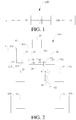
- the engine unit 1 may output at least a part of the power generated thus to the first motor generator 41 via the transmission unit 2a, and the first motor generator 41 may generate electricity and convert mechanical energy into electric energy to be stored in an energy storage component such as a battery component.
- the first motor generator 41 may convert electric energy from the battery component into mechanical energy, and output the mechanical energy to the output unit 5 via the transmission unit 2a to drive the vehicle.
- the synchronizer 6 Because of special application scenarios, compared to a clutch, the synchronizer 6 has the following advantages.
- the transmission power output part 22a includes an output shaft 24, and a driven gear 26 mounted on the output shaft 24 and configured to mesh with the driving gear 25 on the input shaft.
- the driven gears 26 are configured to mesh with the driving gears 25 on the input shafts respectively.
- the number of the driven gears 26 may be the same as that of the input shafts.
- the two driven gears 26 may be configured to mesh with the driving gears 25 on the two input shafts to transmit the power, so as to make the two pairs of gears form two gears for power transmitting.
- the power transmission system 100 in this embodiment may have at least the following operating conditions: a pure electric vehicle (EV) operating condition of the third motor generator 43, a pure EV four-wheel drive operating condition, a parallel operating condition, a series operating condition, and a braking/decelerating feedback operating condition.
- a pure electric vehicle (EV) operating condition of the third motor generator 43 a pure electric vehicle four-wheel drive operating condition, a parallel operating condition, a series operating condition, and a braking/decelerating feedback operating condition.
- This operating condition has the advantages of having better dynamic performance than a single-motor drive, and having better economic efficiency and lower noise than a hybrid drive.
- a typical application highlighting the advantages of this operating condition is traffic congestion at a steep slope (mountain road).
- a pure EV four-wheel drive vehicle has better acceleration performance, gradeability, handling performance and off-road capability. Since two second motor generators 42 and two third motor generators 43 drive four wheels independently, the wheels may obtain different torques and rotating speeds, to achieve the individual control on the four wheels, thus maximizing the dynamic performance, operating stability and off-road performance. Furthermore, when torques in different directions are applied to the left and right wheels by corresponding motor generators, the in-situ steering of the vehicle may be realized.
- This operating condition is a parallel operating condition.
- the dual clutch 31 is in an engaged state
- the synchronizer 6 is in an engaged state
- the engine unit 1 and the first motor generator 41 transfer the power to the driving gear 51 of the final drive via the shift gear set and the synchronizer 6, and the driving gear 51 of the final drive transfers the power to the front wheels 210 via the differential 54
- two second motor generators 42 transfer the power to the corresponding front wheels 210
- two third motor generators 43 transfer the power to the corresponding rear wheels 220.
- This operating condition is mainly applicable to a situation where a load is the largest, for example, during quick acceleration, or climbing steep slopes.
- This operating condition is a series operating condition.
- the dual clutch 31 is in an engaged state
- the synchronizer 6 is in a disengaged state
- the engine unit 1 drives the first motor generator 41 via the dual clutch 31 and the shift gear set to generate electricity
- the second motor generators 42 are configured to drive the front wheels 210 respectively
- the third motor generators 43 are configured to drive the rear wheels 220 respectively.
- This operating condition is mainly applicable to a situation where a load is medium and an electric quantity of a battery is small.
- This operating condition has the advantages that, since the second motor generator 42 and the third motor generator 43 brake four wheels respectively during the decelerating or braking, whether the vehicle is turning or moving straightly, the power of each wheel may be fully absorbed, in the premise of ensuring the braking force and stability of the vehicle, thus maximizing the energy feedback. Moreover, because of the disengagement of the synchronizer 6, while the four motor generators brake the four wheels respectively, the engine unit 1 and the first motor generator 41 may continue generating electricity, so as to enable a stable electricity generation state, avoid frequent switching, and extend the life of components.
- the second motor generators 42 and the third motor generators 43 may respond to the needs of the driver to increase the torque, such that the vehicle is accelerated, unlike a vehicle in the related art, the vehicle needs not to be accelerated only when the synchronizer 6 is in an engaged state.
- the torque compensation in advance may greatly shorten the torque response time and improve the instantaneous acceleration performance of the vehicle.
- the engine unit 1 and the first motor generator 41 may be kept generating electricity, under the braking operating condition and the series operating condition.
- the torque compensation in advance may greatly shorten the motor braking response time and increase the feedback electric quantity.
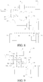
- the power transmission system 100 in this embodiment differs from the power transmission system 100 shown in Fig. 2 in the arrangement of the third motor generators 43.
- each third motor generator 43 drives a corresponding rear wheel 220 via one second speed changing mechanism 72.
- Other parts in this embodiment are substantially the same as those in the power transmission system 100 in the embodiment shown in Fig. 2 , so the detailed description thereof will be omitted here.
- the specific operating conditions of the power transmission system 100 in this embodiment are substantially the same as those of the power transmission system 100 in the embodiment shown in Fig. 2 , except that the power transfer between the third motor generators 43 and the corresponding rear wheels 220 is performed via the second speed changing mechanism 72, which will not be detailed here.
- the differential function of the rear wheels 220 may not be realized by means of only one motor and one speed changing mechanism, however, it would be appreciated that a differential integrally formed with the first speed changing mechanism 71 may be added to realize the differential rotation of the two rear wheels 220.
- the power transmission system 100 in this embodiment differs from the power transmission system 100 shown in Fig. 2 in the arrangement of the second motor generators 42.
- the second motor generators 42 are disposed at two sides of the differential 54 back to back respectively.
- Other parts in this embodiment are substantially the same as those in the power transmission system 100 in the embodiment shown in Fig. 2 , so the detailed description thereof will be omitted here.
- the specific operating conditions of the power transmission system 100 in this embodiment are substantially the same as those of the power transmission system 100 in the embodiment shown in Fig. 2 , which will not be detailed here.
- the power transmission system 100 in this embodiment differs from the power transmission system 100 shown in Fig. 5 in the arrangement of the third motor generators 43.
- each third motor generator 43 drives a corresponding rear wheel 220 via one second speed changing mechanism 72.
- Other parts in this embodiment are substantially the same as those in the power transmission system 100 in the embodiment shown in Fig. 2 , so the detailed description thereof will be omitted here.
- the specific operating conditions of the power transmission system 100 in this embodiment are substantially the same as those of the power transmission system 100 in the embodiment shown in Fig. 2 , which will not be detailed here.
- the power transmission system 100 in this embodiment differs from the power transmission system 100 shown in Fig. 5 in the arrangement of the third motor generators 43.
- one third motor generator 43 is provided and drives the rear wheels 220 via one first speed changing mechanism 71.
- Other parts in this embodiment are substantially the same as those in the power transmission system 100 in the embodiment shown in Fig. 5 , so the detailed description thereof will be omitted here.
- the specific operating conditions of the power transmission system 100 in this embodiment are substantially the same as those of the power transmission system 100 in the embodiment shown in Fig.
- the differential function of the rear wheels 220 may not be realized by means of only one motor and one speed changing mechanism, however, it would be appreciated that a differential integrally formed with the first speed changing mechanism 71 may be added to realize the differential rotation of the two rear wheels 220.
- the power transmission system 100 in this embodiment differs from the power transmission system 100 shown in Fig. 2 in the type of the clutch as well as the number of the input shafts, the driving gears 25 and the driven gears 26.
- the clutch is a triple clutch 32, three input shafts are provided, and correspondingly three pairs of driving gears 25 and driven gears 26 are provided.
- Other parts in this embodiment are substantially the same as those in the power transmission system 100 in the embodiment shown in Fig. 2 , so the detailed description thereof will be omitted here.
- the power transmission system 100 in this embodiment differs from the power transmission system 100 shown in Fig. 2 in that the third motor generators 43 in the embodiment shown in Fig. 2 are eliminated, and the power transmission system 100 in this embodiment is operable in a two-wheel drive mode.
- the power transmission system 100 in this embodiment may have at least the following operating conditions.
- This operating condition is a pure EV operating condition of the second motor generator 42.
- the dual clutch 31 is in a disengaged state
- the synchronizer 6 is in a disengaged state
- the engine unit 1 and the first motor generator 41 do not operate
- the second motor generators 42 drive the front wheels 210 directly.
- This operating condition is mainly applicable to a situation where a load is small and an electric quantity of a battery is large, for example, during uniform motions or under urban operating conditions.
- This operating condition has the advantages that, since the second motor generators 42 directly drive the front wheels 210, the transmission chain is the shortest, and operating components are the fewest, thus achieving maximum transmission efficiency and minimum noise. Moreover, since the second motor generators 42 independently drive the left front wheel 210 and the right front wheel 210 respectively, an electronic differential function may be achieved, thus increasing the handling stability and reducing the amount of tire wear.
- This operating condition is a pure EV operating condition of three motors.
- the dual clutch 31 is in a disengaged state, the synchronizer 6 is in an engaged state, the engine unit 1 does not operate, the first motor generator 41 transfers the power to the driving gear 51 of the final drive via the shift gear set and the synchronizer 6, and the driving gear 51 of the final drive evenly distributes the power to the left and right front wheels 210 via the differential 54, while the second motor generators 42 directly drive the left and right front wheels 210.
- This operating condition is mainly applicable to a situation where a load is large and an electric quantity of a battery is large, for example, during acceleration, climbing, overtaking, or high-speed running.
- This operating condition has the advantages of having better dynamic performance than a single-motor drive, and having better economic efficiency and lower noise than a hybrid drive.
- a typical application highlighting the advantages of this operating condition is traffic congestion at a steep slope (mountain road).
- This operating condition is a parallel operating condition.
- the dual clutch 31 is in a disengaged state
- the synchronizer 6 is in an engaged state
- the engine unit 1 and the first motor generator 41 transfer the power to the driving gear 51 of the final drive via the shift gear set and the synchronizer 6
- the driving gear 51 of the final drive evenly distributes the power to the left and right front wheels via the differential 54
- the second motor generators 42 directly drive the left and right front wheels.
- This operating condition is mainly applicable to a situation where a load is the largest, for example, during quick acceleration, or climbing steep slopes.
- This operating condition has the advantages that three motors and the engine unit 1 drive the vehicle simultaneously, thus maximizing the dynamic performance.
- This operating condition is a series operating condition.
- the dual clutch 31 is in an engaged state
- the synchronizer 6 is in a disengaged state
- the engine unit 1 drives the first motor generator 41 via the dual clutch 31 and the shift gear set to generate electricity
- the second motor generators 42 directly drive the wheels.
- This operating condition is mainly applicable to a situation where a load is medium and an electric quantity of a battery is small.
- This operating condition has the advantages that, since the second motor generators 42 directly drive the wheels, the transmission chain is the shortest, and operating components are the fewest, thus achieving maximum transmission efficiency and minimum noise.
- the first motor generator 41 may keep the engine unit 1 running in an optimal economic region through torque and rotating speed adjustment, thus reducing fuel consumption during the electricity generation.
- the second motor generators 42 independently drive the left front wheel and the right front wheel respectively, an electronic differential function may be achieved, thus increasing the handling stability and reducing the amount of tire wear.
- This operating condition is a braking/decelerating feedback operating condition.
- the dual clutch 31 is in an engaged state, the synchronizer 6 is in a disengaged state, the engine unit 1 drives the first motor generator 41 to generate electricity, and the second motor generator 42 directly brakes the wheels and generates electricity.
- This operating condition is mainly used for braking or decelerating the vehicle.
- This operating condition has the advantages that, since the second motor generator 42 brake two wheels respectively during the decelerating or braking of the vehicle, the braking energy may be absorbed to the largest extent and converted into electric energy, and the engine unit 1 and the first motor generator 41 may continue generating electricity, to enable a stable electricity generation state and avoid frequent switching.
- the power transmission system may switch from the fourth operating condition to the third operating condition.
- the first motor generator 41 may adjust the rotating speed of the output shaft 24 with the rotating speed of the driving gear 51 of the final drive as a target value through the rotating speed control, so as to match the rotating speed of the output shaft 24 with the rotating speed of the driving gear 51 of the final drive as far as possible, thus facilitating the engagement of the synchronizer 6.
- the second motor generators 42 may respond to the needs of the driver to increase the torque, such that the vehicle is accelerated, unlike a vehicle in the related art, the vehicle does not require the synchronizer 6 to be in an engaged state in order to be accelerated.
- the torque compensation in advance may greatly shorten the torque response time and improve the instantaneous acceleration performance of the vehicle.
- the switching from the fourth operating condition to the fifth operating condition will be described as follows.
- the power transmission system 100 may switch from the fourth operating condition to the fifth operating condition.
- the second motor generators 42 may meet the braking feedback requirements, and the feedback of the first motor generator 41 is not needed.
- the second motor generators 42 may instantly respond to the needs of the driver to brake the wheels and feed back the electric quantity, unlike a vehicle in the related art, the vehicle does not require the synchronizer 6 to be in an engaged state to feed back the electric quantity.
- the power transmission system 100 in this embodiment differs from the power transmission system 100 shown in Fig. 9 in the arrangement of the second motor generators 42.
- the second motor generators 42 are disposed at two sides of the differential 54 back to back respectively.
- Other parts in this embodiment are substantially the same as those in the power transmission system 100 in the embodiment shown in Fig. 9 , so the detailed description thereof will be omitted here.
- the power transmission system 100 in this embodiment differs from the power transmission system 100 shown in Fig. 9 in the arrangement of the second motor generators 42.
- two second motor generators 42 are provided, and each second motor generator 42 drives a corresponding rear wheel 220 via one fourth speed changing mechanism 74.
- Other parts in this embodiment are substantially the same as those in the power transmission system 100 in the embodiment shown in Fig. 9 , so the detailed description thereof will be omitted here.
- the power transmission system 100 in this embodiment may have at least the following operating conditions.
- This operating condition is a pure EV four-wheel drive operating condition.
- the dual clutch 31 is in a disengaged state, the synchronizer 6 is in an engaged state, the engine unit 1 does not operate, the first motor generator 41 drives the front wheels respectively, and the second motor generators 42 drive the rear wheels respectively.
- This operating condition is mainly applicable to a situation where a load is large and an electric quantity of a battery is large, for example, during acceleration, climbing, overtaking, or high-speed running.
- This operating condition has the advantages of having better dynamic performance than a single-motor drive, and having better economic efficiency and lower noise than a hybrid drive.
- a typical application highlighting the advantages of this operating condition is traffic congestion at a steep slope (mountain road).
- a pure EV four-wheel drive vehicle has better acceleration performance, gradeability, handling performance and off-road capability.
- the second motor generators 42 independently drive the left rear wheel and the right rear wheel respectively, an electronic differential function may be achieved, thus increasing the handling stability and reducing the amount of tire wear.
- This operating condition is a parallel operating condition.
- the dual clutch 31 is in a disengaged state
- the synchronizer 6 is in an engaged state
- the engine unit 1 and the first motor generator 41 drive the front wheels 210 simultaneously
- the second motor generators 42 drive the rear wheels respectively.
- This operating condition is mainly applicable to a situation where a load is the largest, for example, during quick acceleration, or climbing steep slopes.
- This operating condition has the advantages that two motor generators and the engine unit drive the vehicle simultaneously, thus maximizing the dynamic performance.
- a HEV four-wheel drive vehicle has better acceleration performance, gradeability, handling performance and off-road capability.
- the second motor generators 42 independently drive the left rear wheel and the right rear wheel respectively, an electronic differential function may be achieved, thus increasing the handling stability and reducing the amount of tire wear.
- This operating condition is a series operating condition.
- the dual clutch 31 is in an engaged state
- the synchronizer 6 is in a disengaged state
- the engine unit 1 drives the first motor generator 41 to generate electricity
- the second motor generators 42 drive the rear wheels respectively.
- This operating condition is mainly applicable to a situation where a load is medium and an electric quantity of a battery is small.
- This operating condition has the advantages that, since the two second motor generators independently drive the left rear wheel and the right rear wheel respectively, an electronic differential function may be achieved, thus increasing the handling stability and reducing the amount of tire wear.
- the vehicle under the series operating condition has better acceleration performance, gradeability, and steering capability.
- the first motor generator 41 may keep the engine unit 1 running in an optimal economic region through torque and rotating speed adjustment, thus reducing fuel consumption during the electricity generation.
- This operating condition is a braking/decelerating feedback operating condition.
- the dual clutch 31 is in a disengaged state, the synchronizer 6 is in an engaged state, the engine unit does not operate, and the first motor generator and the second motor generators brake the vehicle and generate electricity simultaneously.
- This operating condition has the advantages that, since three motors brake the vehicle simultaneously during the decelerating or braking of the vehicle, the braking energy may be absorbed to the largest extent and converted into electric energy.
- the disengagement of the dual clutch the braking of the vehicle by the friction torque of the engine unit may be eliminated, so that more power is left to be absorbed by the motor.
- the braking force may be distributed to front and rear motors in the premise of ensuring the braking force of the vehicle, and more electric energy may be fed back compared to a front-wheel drive vehicle or a rear-wheel drive vehicle.
- two second motor generators may control the braking force independently, thus improving the handling stability of the vehicle during braking when turning, and further increasing the feedback energy.
- the operating conditions of the power transmission system 100 in this embodiment may be switched, and typical switching between operating conditions is switching from the fourth operating condition to the third operating condition, or switching from the fourth operating condition to the fifth operating condition.
- the switching between the operating conditions of the power transmission system 100 in this embodiment is similar to that in the above embodiments, so the detailed description thereof will be omitted here.
- the power transmission system 100 in this embodiment differs from the power transmission system 100 shown in Fig. 9 in the arrangement of the second motor generators 42.
- one second motor generators 42 is provided, and the second motor generator 42 drives the rear wheels 220 via one third speed changing mechanism 73.
- Other parts in this embodiment are substantially the same as those in the power transmission system 100 in the embodiment shown in Fig. 9 , so the detailed description thereof will be omitted here.
- the second motor generator 42 may be used to drive the vehicle separately.
- the dual clutch 31 and the synchronizer 6 are in a disengaged state.
- This operating condition is mainly applicable to a situation where a load is small and an electric quantity of a battery is large, for example, during uniform motions or under urban operating conditions.
- This operating condition has the advantages that, since the second motor generators 42 directly drive the rear wheels 220 via the third speed changing mechanism 73, compared to a front-wheel drive vehicle, the vehicle in this embodiment has better acceleration performance, gradeability and steering capability.
- the synchronizer 6 In a front-wheel drive part, the synchronizer 6 is in a disengaged state, so there is no mechanical loss in the front-wheel drive part, thus reducing the energy consumption of the vehicle.
- a differential integrally formed with the third speed changing mechanism 73 may also be added.
- the power transmission system 100 may also have a pure EV four-wheel drive operating condition.
- the dual clutch 31 is in a disengaged state
- the synchronizer 6 is in an engaged state
- the engine unit 1 does not operate
- the first motor generator 41 drives the front wheels 210 respectively
- the second motor generator 42 drives the rear wheels 220 respectively.
- This operating condition is mainly applicable to a situation where a load is large and an electric quantity of a battery is large, for example, during acceleration, climbing, overtaking, or high-speed running.
- This operating condition has better dynamic performance than a single-motor drive, and has better economic efficiency and lower noise than a hybrid drive.
- a typical application highlighting the advantages of this operating condition is traffic congestion at a steep slope (mountain road).
- a pure EV four-wheel drive vehicle has better acceleration performance, gradeability, handling performance and off-road capability.
- the power transmission system may also have a parallel operating condition.
- the dual clutch 31 is in an engaged state
- the synchronizer 6 is in an engaged state
- the engine unit 1 and the first motor generator 41 drive the front wheels 210 simultaneously
- the second motor generator 42 drives the rear wheels 220.
- This operating condition is mainly applicable to a situation where a load is the largest, for example, during quick acceleration, or climbing steep slopes.
- This operating condition has the advantages that two motors and the engine unit 1 drive the vehicle simultaneously, thus maximizing the dynamic performance.
- a HEV four-wheel drive vehicle has better acceleration performance, gradeability, handling performance and off-road capability.
- the power transmission system may also have a series operating condition.
- the dual clutch 31 is in an engaged state
- the synchronizer 6 is in a disengaged state
- the engine unit 1 drives the first motor generator 41 to generate electricity
- the second motor generator drives the rear wheels.
- This operating condition is mainly applicable to a situation where a load is medium and an electric quantity of a battery is small.
- This operating condition has the advantages that the second motor generator 42 drives the rear wheels, and compared to a front-wheel drive vehicle, the vehicle under the series operating condition has better acceleration performance, gradeability and steering capability.
- the first motor generator 41 may keep the engine unit 1 running in an optimal economic region through torque and rotating speed adjustment, thus reducing fuel consumption during the electricity generation.
- the braking force may be distributed to front and rear motors in the premise of ensuring the braking force of the vehicle, and more electric energy may be fed back compared to a front-wheel drive vehicle or a rear-wheel drive vehicle.
- the operating conditions of the power transmission system 100 in this embodiment may be switched, and typical switching between operating conditions is switching from the fourth operating condition to the third operating condition, or switching from the fourth operating condition to the fifth operating condition.
- the switching between the operating conditions of the power transmission system 100 in this embodiment is similar to that in the above embodiments, so the detailed description thereof will be omitted here.
- the power transmission system 100 in this embodiment differs from the power transmission system 100 shown in Fig. 9 in the arrangement of the second motor generators 42.
- two second motor generators 42 are provided and are wheel-side motors, and each second motor generator 42 drives a corresponding rear wheel 220.
- Other parts in this embodiment are substantially the same as those in the power transmission system 100 in the embodiment shown in Fig. 9 , so the detailed description thereof will be omitted here.
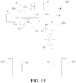
- the engine unit 1 is coupled with the input terminal 313 of the dual clutch 31, the first output terminal 311 of the dual clutch 31 is coupled with the first input shaft 21, the second output terminal 312 of the dual clutch 31 is coupled with the second input shaft 22, and the second input shaft 22 is coaxially fitted over the first input shaft 21.
- Each of the first input shaft 21 and the second input shaft 22 is provided with one driving gear 25 by fixing, the double-linked gear structure 26 (i.e. a driven gear) is freely fitted over the output shaft 24, the first gear part 261 of the double-linked gear structure 26 is configured to mesh with the driving gear 25 on the first input shaft 21, and the second gear part 262 of the double-linked gear structure 26 is configured to mesh with the driving gear 25 on the second input shaft 22.
- the double-linked gear structure 26 i.e. a driven gear
- a first intermediate shaft gear 451 and a second intermediate shaft gear 452 are fixed on the intermediate shaft 45.
- the first intermediate shaft gear 451 is configured to mesh with the driving gear 25 on the second input shaft 22. Indirect power transmitting between the output terminal of the first motor generator 41 and the second intermediate shaft gear 452 via an intermediate idler 44 is performed.
- the synchronizer 6 is disposed on the output shaft 24 and configured to engage with the double-linked gear structure 26.
- the driving gear 51 of the final drive is fixed on the output shaft 24.
- the driving gear 51 of the final drive is configured to externally mesh with the driven gear 53 of the final drive, and the driven gear 53 of the final drive may be fixed on a shell of the differential 54, so as to transfer the power to the differential 54.
- the differential 54 distributes the power and adaptively transfers the distributed power to half axles at two sides of the vehicle, so as to drive the wheels 200.
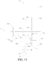
- a first intermediate shaft gear 451 and a second intermediate shaft gear 452 are fixed on the intermediate shaft 45.
- the first intermediate shaft gear 451 is configured to mesh with the driving gear 25 on the second input shaft 22.
- the output terminal of the first motor generator 41 is configured to directly mesh with the second intermediate shaft gear 452 for power transmitting.
- the power transmission system 100 may further include the second motor generator 42 and the third motor generator 43 or only include the third motor generator 43 (not shown in Figs. 14-19 ), and the arrangement of the second motor generator 42 and the third motor generator 43 may be the same as that in Figs. 2-13 , for example, being in a wheel-side form, or being disposed at two sides of the differential back to back.
- the driving gear 51 of the final drive of the power transmission system 100 shown in Figs. 14-19 may be configured to drive the front wheels 210, and the rear-wheel drive may be the same as that shown in Fig. 12 , i.e. the rear wheels 220 are driven by one second motor generator 42 and one reducing mechanism.
- embodiments of the present disclosure further provide a vehicle including the abovementioned power transmission system 100.
- other components e.g., a driving system, a steering system, and a braking system
- a driving system e.g., a steering system, and a braking system
- a condition for entering cruise control is determined. When all preset cruise control conditions are met, the vehicle enters cruise.
- the EV mode cruise strategy and the HEV mode cruise strategy are respectively provided for different operating modes of the vehicle, so as to meet cruise requirements of an automobile of a user in different operating modes.
- a control method for the EV cruise mode and a control method for the HEV cruise mode are respectively described below by using two specific embodiments.
- the required torque Tc of the vehicle is calculated, so that in a low-electric quantity strategy, if the current SOC of the power battery of the vehicle is less than the second electric quantity threshold value SOC2 and the output torque upper limit of the engine unit is greater than the required torque, the engine unit is controlled to output the required torque.
- the engine unit is controlled to drive the first motor generator to generate electricity. If the output torque upper limit of the engine unit is less than the required torque, the second motor generator and the first motor generator are controlled to successively perform torque compensation output.
- the engine unit performs output according to the output torque upper limit Te of the engine unit, the second motor generator and the first motor generator successively compensate for the remaining torque, and the output torque of the second motor generator and the first motor generator is Tc-Te.
- the engine unit when the vehicle enters the HEV cruise mode, if it is determined that the current SOC of the power battery of the vehicle is less than the second electric quantity threshold value SOC2, and when the output torque upper limit Te of the engine unit is less than required torque Tc, the engine unit is controlled to output the output torque upper limit Te of the engine unit, and according to the method shown in Fig. 4 in some embodiments of the present disclosure, the second motor generator is first controlled to perform torque compensation output, and when the second motor generator also cannot fully compensate for the remaining torque, the first motor generator is then controlled to perform torque compensation output.
- S1112 Compare the required torque Tc of the current cruise mode of the vehicle with the output torque upper limit Te of the engine unit, to determine the range of the required torque Tc of the current cruise mode.
- the engine unit outputs the torque Tc, and the first motor and the second motor do not perform output. That is, after the vehicle enters the HEV cruise mode, if it is determined that the current SOC of the power battery of the vehicle is greater than or equal to the second electric quantity threshold value SOC2 and is less than or equal to the third electric quantity threshold value SOC3, and when the output torque upper limit Te of the engine unit is greater than or equal to the required torque Tc of the vehicle, the engine unit is controlled to output a torque according to the cruise required torque Tc of the vehicle.
- Step S1115 When it is determined that the output torque upper limit Te of the engine unit is less than the required torque Tc, perform Step S1116.
- S1119 Compare the required torque Tc of the current cruise mode of the vehicle with the output torque upper limit Tm2 of the second motor generator, and determine the range of the required torque Tc of the current cruise mode.
- the torque output by the second motor generator is the required torque Tc. That is, after the vehicle enters the HEV cruise mode, if it is determined that the current SOC of the power battery of the vehicle is greater than the third electric quantity threshold value SOC3, and when the output torque upper limit Tm2 of the second motor generator is greater than or equal to the required torque Tc, the second motor generator is controlled to output a torque according to the required cruise torque Tc of the vehicle.
- the second motor generator performs output according to the output torque upper limit Tm2 of the second motor generator, and the engine unit and the first motor generator successively compensate for the remaining torque, where the output torque of the engine unit and the first motor generator is Tc-Tm2.
- the second motor generator when the vehicle enters the HEV cruise mode, if it is determined that the current SOC of the power battery of the vehicle is greater than the third electric quantity threshold value SOC3, and when the output torque upper limit Tm2 of the second motor generator is less than the required torque Tc, the second motor generator is controlled to output the output torque upper limit Tm2 of the second motor generator, the engine unit is first controlled to perform torque compensation output, and when the engine unit also cannot fully compensate for the remaining torque, the first motor generator is then controlled to perform torque compensation output.
- the electric quantity SOC of the battery is compared with the second electric quantity threshold value SOC2, the third electric quantity threshold value SOC3.
- the cruise control method for a HEV mode is correspondingly classified into the low-electric quantity strategy, the intermediate-electric quantity strategy, and the high-electric quantity strategy, and different power distribution strategies for the engine unit, the first motor generator, and the second motor generator are separately provided for the foregoing three strategies.
- the engine unit first performs driving, and within the economic region, the engine unit is controlled to drive the first motor generator to generate electricity.
- a method for determining to exit cruise in the foregoing cruise control method for a vehicle specifically includes the following steps: S1201: Determine whether a cruise main switch or a cruise cancel button is triggered, that is, is pressed. If yes, perform Step S1214; or if not, perform Step S1202.
- Step S1202 Determine whether the current cruise speed V is less than the preset lower limit value Vmin. If yes, perform Step S1214; or if not, perform Step S1203.
- Step S1203 Determine whether the braking pedal is depressed. If yes, perform Step S1214; or if not, perform Step S1204.
- Step S1204 Determine whether the current gear is changed to a gear other than gear D. If yes, perform Step S1214; or if not, perform Step S1205.
- Step S1205 Determine whether the cruise control switch is in an abnormal state. If yes, perform Step S314; or if not, perform Step S1206.
- Step S1206 Determine whether the speed signal is in an abnormal state. If yes, perform Step S1214; or if not, perform Step S1207.
- Step S1207 Determine whether the braking signal is in an abnormal state. If yes, perform Step S1214; or if not, perform Step S1208.
- Step S1209 Determine whether the EPB requests to cancel cruise. If yes, perform Step S1214; or if not, perform Step S1210.
- Step S1210 Determine whether the ESP works. If yes, perform Step S1214; or if not, perform Step S1211.
- Step S1211 Determine whether the EPB/ESP fails. If yes, perform Step S1214; or if not, perform Step S1212.
- Step S1201 to Step S1212 If during the cruise process, none of the conditions in Step S1201 to Step S1212 is met, continue with the cruise, and determining is performed cyclically from Step S1201 to Step S1212 during the cruise.
- Step S1201 to Step S1212 the vehicle is controlled to exit the cruise mode.
- the vehicle exits cruise control, and the cruise mode cannot automatically restore that is, after the vehicle exits cruise, if the user does not enter a cruise operation again, the vehicle cannot automatically restore the cruise mode.
- the vehicle may cruise in operating modes: the EV mode and the HEV mode, and cruise control strategies in the two operating modes are provided.
- the cruise control strategies are, for example, a control strategy for an EV cruise mode in which the first motor generator and the second motor generator are used to perform torque output to perform cruise and a control strategy for a HEV cruise mode in which the engine unit, the first motor generator, and the second motor generator jointly perform output to perform cruise.
- the cruise control strategy for the EV mode cannot meet a cruise requirement, the engine unit is automatically started, and the vehicle is switched to the cruise control strategy for the HEV mode.
- the control method for entering cruise and exiting cruise is added. Therefore, safety of a user can be ensured while a normal cruise function of the vehicle is ensured.
- a user can control the vehicle to cruise in an EV mode and a HEV mode, so that a pure EV cruise requirement of the user can be met, and fuel consumption can be reduced. It can also be ensured that when the pure EV cannot meet the cruise requirement, the vehicle automatically switches to a cruise control strategy for a HEV mode, so that it is ensured that the user can perform cruise driving continuously and reliably.
- the cruise control strategies in two different operating modes meet different driving requirements of the user, so as to implement combination of selection of a driving mode and an automatic cruise function for running at a constant speed, and bring convenience to driving while fuel consumption can be reduced, making it more economical and environmentally friendly.
- the transmission unit 2a is adapted to selectively be coupled with the engine unit 1.
- the first motor generator 41 is coupled with the transmission unit 2a.
- the output unit 5 is configured to transmit the power transmitted by the transmission unit 2a to at least one of front and rear wheels of the vehicle.
- the power switching device e.g., the synchronizer 6) is adapted to enable or interrupt a transmitting of power between the transmission unit 2a and the output unit 5.
- the second motor generator 42 is configured to drive the front wheels or rear wheels.
- the power battery 300 is connected to the first motor generator 41 and/or the second motor generator 42 to supply power to the first motor generator 41 and/or the second motor generator 42.
- the controller 500 determines whether the vehicle meets a preset cruise control condition, and when the vehicle meets the preset cruise control condition, the controller 500 controls the vehicle according to the current operating mode of the vehicle to enter a corresponding cruise mode, where when the current operating mode of the vehicle is an EV mode, the controller 500 controls the vehicle to enter an EV cruise mode, and when the current operating mode of the vehicle is a HEV mode, the controller 500 controls the vehicle to enter a HEV cruise mode.
- the controller 500 controls the vehicle not to enter a corresponding cruise mode.
- the vehicle is in the cruise mode, if any condition of the preset cruise control conditions is not met or when a signal for the vehicle to exit cruise control is detected, the vehicle is controlled to exit the corresponding cruise mode. Therefore, safety of a user can be further ensured while it is ensured that the vehicle maintains a normal cruise function.
- the controller 500 controls the engine unit 1 to start, and controls the vehicle to enter the HEV cruise mode.
Landscapes
- Engineering & Computer Science (AREA)
- Transportation (AREA)
- Mechanical Engineering (AREA)
- Chemical & Material Sciences (AREA)
- Combustion & Propulsion (AREA)
- Automation & Control Theory (AREA)
- Human Computer Interaction (AREA)
- Electric Propulsion And Braking For Vehicles (AREA)
- Hybrid Electric Vehicles (AREA)
Claims (10)
- Verfahren zur Fahrtregelung für ein Fahrzeug, wobei das Fahrzeug eine Motoreinheit (1), eine Getriebeeinheit (2a), die dazu eingerichtet ist, selektiv mit der Motoreinheit (1) gekoppelt zu werden, und auch dazu konfiguriert ist, die von der Motoreinheit (1) erzeugte Leistung zu übertragen, einen ersten Motorgenerator (41), der mit der Getriebeeinheit (2a) gekoppelt ist, eine Ausgangseinheit (5), eine Leistungsschaltvorrichtung (6), einen zweiten Motorgenerator (42), der dazu konfiguriert ist, Vorderräder und/oder Hinterräder (210, 220) anzutreiben, und eine Leistungsbatterie (300), die den ersten Motorgenerator (41) und/oder den zweiten Motorgenerator (42) mit Energie versorgt, umfasst, wobei die Ausgangseinheit (5) dazu konfiguriert ist, die von der Getriebeeinheit (2a) übertragene Leistung an zumindest eines von Vorder- und Hinterrädern (210, 220) des Fahrzeugs zu übertragen, die Leistungsschaltvorrichtung (6) dazu eingerichtet ist, eine Leistungsübertragung zwischen der Getriebeeinheit (2a) und der Ausgangseinheit (5) zu ermöglichen oder zu unterbrechen, und das Verfahren zur Fahrtregelung die folgenden Schritte umfasst:Bestimmen, ob das Fahrzeug eine voreingestellte Fahrtregelungsbedingung erfüllt, wenn ein Signal für den Eintritt des Fahrzeugs in die Fahrtregelung erfasst wird;Steuern des Fahrzeugs gemäß einem aktuellen Betriebsmodus des Fahrzeugs, wenn das Fahrzeug die voreingestellte Fahrtregelungsbedingung erfüllt, um in einen entsprechenden Fahrtmodus einzutreten, wobei das Fahrzeug so gesteuert wird, dass es in einen EV-Fahrtmodus eintritt, wenn der aktuelle Betriebsmodus des Fahrzeugs ein Elektrofahrzeug (EV)-Modus ist,, und das Fahrzeug so gesteuert wird, dass es in einen HEV-Fahrtmodus eintritt, wenn der aktuelle Betriebsmodus des Fahrzeugs ein Hybrid-Elektrofahrzeug (HEV)-Modus ist;dadurch gekennzeichnet, dass die voreingestellte Fahrtregelungsbedingung Folgendes umfasst:(1) die aktuelle Geschwindigkeit des Fahrzeugs ist größer als oder gleich wie ein voreingestellter unterer Grenzwert der Fahrgeschwindigkeit und ist kleiner als oder gleich wie ein voreingestellter oberer Grenzwert der Fahrgeschwindigkeit;(2) ein aktueller Gang des Fahrzeugs ist der Gang D;(3) ein Bremspedal des Fahrzeugs wird nicht ausgelöst;(4) ein Fahrtregelungsschalter des Fahrzeugs befindet sich in einem normalen Zustand;(5) ein Geschwindigkeitssignal des Fahrzeugs befindet sich in einem normalen Zustand;(6) ein Bremssignal des Fahrzeugs befindet sich in einem normalen Zustand;(7) ein Gaspedalsignal des Fahrzeugs befindet sich in einem normalen Zustand;(8) ein elektrisches Parkbrems-(EPB-) System des Fahrzeugs verlangt nicht, die Fahrtregelung des Fahrzeugs aufzuheben;(9) ein elektronisches Stabilitätsprogramm-(ESP)-System des Fahrzeugs wird nicht ausgeführt;(10) das EPB/ESP des Fahrzeugs hat keinen Ausfall; und(11) Kommunikation mit der EPB/ESP funktioniert einwandfrei, undwobei, wenn sich das Fahrzeug in dem Fahrtmodus befindet, das Fahrzeug so gesteuert wird, dass es den entsprechenden Fahrtmodus verlässt, wenn eine beliebige Bedingung der voreingestellten Fahrtregelungsbedingungen nicht erfüllt ist oder ein Signal zum Verlassen der Fahrtregelung erfasst wird.
- Verfahren zur Fahrtregelung für ein Fahrzeug nach Anspruch 1, wobei die Leistungsschaltvorrichtung (6) als Synchronisiereinrichtung (6) konfiguriert ist und die Synchronisiereinrichtung (6) dazu eingerichtet ist, selektiv zwischen der Ausgangseinheit (5) und der Getriebeeinheit (2a) zu synchronisieren.
- Verfahren zur Fahrtregelung für ein Fahrzeug nach Anspruch 1 oder 2, das, wenn sich das Fahrzeug in dem EV-Fahrtmodus befindet, Folgendes umfasst:Berechnen eines erforderlichen Drehmoments des Fahrzeugs und Steuern des zweiten Motorgenerators (42), um das erforderliche Drehmoment auszugeben, wenn ein aktueller Ladezustand (SOC) der Leistungsbatterie (300) größer als ein erster Schwellenwert einer elektrischen Größe ist, eine maximal zulässige Entladeleistung der Leistungsbatterie (300) größer als ein vorgegebener Leistungsschwellenwert ist und die aktuelle Steigung des Fahrzeugs kleiner als ein Steigungsschwellenwert ist, und wenn eine obere Grenze des Ausgangsdrehmoments des zweiten Motorgenerators (42) kleiner als das erforderliche Drehmoment ist, Steuern des ersten Motorgenerators (41), um eine Drehmomentkompensationsausgabe durchzuführen; undwenn ein aktueller SOC der Leistungsbatterie (300) kleiner als oder gleich wie ein erster Schwellenwert einer elektrischen Größe ist, eine maximal zulässige Entladeleistung der Leistungsbatterie (300) kleiner als oder gleich wie ein voreingestellter Leistungsschwellenwert ist oder die aktuelle Steigung des Fahrzeugs größer als oder gleich wie ein Steigungsschwellenwert ist, Steuern der Motoreinheit (1) zum Starten und Steuern des Fahrzeugs zum Eintritt in den HEV-Fahrtmodus.
- Verfahren zur Fahrtregelung für ein Fahrzeug nach einem der Ansprüche 1 bis 3, wobei ein erforderliches Drehmoment des Fahrzeugs berechnet wird, wenn das Fahrzeug in den HEV-Reisemodus eintritt, und das Verfahren umfasst:Steuern der Motoreinheit (1), um das erforderliche Drehmoment abzugeben, wenn ein aktueller SOC der Leistungsbatterie (300) kleiner als ein zweiter Schwellwert der elektrischen Größe ist und eine obere Grenze des Ausgangsdrehmoments der Motoreinheit (1) größer als das erforderliche Drehmoment ist, und Steuern der Motoreinheit, um den ersten Motorgenerator (41) anzutreiben, um Elektrizität zu erzeugen, wenn das Fahrzeug in einem wirtschaftlichen Modus läuft; undSteuern des zweiten Motorgenerators (42) und des ersten Motorgenerators (41), um nacheinander eine Drehmomentkompensationsausgabe durchzuführen, wenn die obere Grenze des Ausgangsdrehmoments der Motoreinheit (1) kleiner als das erforderliche Drehmoment ist.
- Verfahren zur Fahrtregelung für ein Fahrzeug nach Anspruch 4, wobei
die Motoreinheit (1) so gesteuert wird, dass sie das erforderliche Drehmoment ausgibt, wenn der aktuelle SOC der Leistungsbatterie (300) größer oder gleich dem zweiten Schwellenwert der elektrischen Größe und kleiner oder gleich einem dritten Schwellenwert der elektrischen Größe ist und die obere Grenze des Ausgangsdrehmoments der Motoreinheit (1) größer als das erforderliche Drehmoment ist, wobei der dritte Schwellenwert der elektrischen Größe größer als der zweite Schwellenwert der elektrischen Größe ist; und
der zweite Motorgenerator (42) und der erste Motorgenerator (41) gesteuert werden, um nacheinander eine Drehmomentkompensationsausgabe durchzuführen, wenn die obere Grenze des Ausgangsdrehmoments der Motoreinheit (1) kleiner als das erforderliche Drehmoment ist, oder wobei
der zweite Motorgenerator (42) so gesteuert wird, dass er das erforderliche Drehmoment ausgibt, wenn ein Strom-SOC der Leistungsbatterie (300) größer als ein dritter Schwellenwert der elektrischen Größe ist und eine obere Grenze des Ausgangsdrehmoments des zweiten Motorgenerators (42) größer als das erforderliche Drehmoment ist; und
die Motoreinheit (1) und der erste Motorgenerator (41) gesteuert werden, um nacheinander eine Drehmomentkompensationsausgabe durchzuführen, wenn die obere Grenze des Ausgangsdrehmoments des zweiten Motorgenerators (42) kleiner als das erforderliche Drehmoment ist. - Fahrzeug, umfassend:eine Motoreinheit (1);eine Getriebeeinheit (2a), die dazu eingerichtet ist, selektiv mit der Motoreinheit (1) gekoppelt zu werden, und auch dazu konfiguriert ist, die von der Motoreinheit (1) erzeugte Leistung zu übertragen;einen ersten Motorgenerator (41), der mit der Getriebeeinheit (2a) gekoppelt ist;eine Ausgangseinheit (5), die dazu konfiguriert ist, die von der Getriebeeinheit (2a) übertragene Leistung auf zumindesten eines von Vorder- und Hinterrädern (210, 220) des Fahrzeugs zu übertragen;eine Leistungsschaltvorrichtung (6), die dazu eingerichtet ist, eine Leistungsübertragung zwischen der Getriebeeinheit (2a) und der Ausgangseinheit (5) zu ermöglichen oder zu unterbrechen;einen zweiten Motorgenerator (42), der dazu konfiguriert ist, die Vorderräder (210) oder die Hinterräder (220) anzutreiben;eine Leistungsbatterie (300), die mit dem ersten Motorgenerator (41) und/oder dem zweiten Motorgenerator (42) verbunden ist, um den ersten Motorgenerator (41) und/oder den zweiten Motorgenerator (42) mit Energie zu versorgen; undeine Steuerung (500), wobei die Steuerung (500) bestimmt, ob das Fahrzeug eine voreingestellte Geschwindigkeitsregelungsbedingung erfüllt, wenn ein Signal für das Fahrzeug zum Eintreten in die Fahrtregelung erfasst wird, und die Steuerung (500) das Fahrzeug gemäß einem aktuellen Betriebsmodus des Fahrzeugs steuert, um in einen entsprechenden Geschwindigkeitsmodus einzutreten, wenn das Fahrzeug die voreingestellte Fahrtregelungsbedingung erfüllt, wobei die Steuerung (500) das Fahrzeug so steuert, dass es in einen EV-Fahrtmodus eintritt, wenn der aktuelle Betriebsmodus des Fahrzeugs ein Elektrofahrzeug (EV) Modus ist, und die Steuerung (500) das Fahrzeug so steuert, dass es in einen HEV-Fahrtmodus eintritt, wenn ein aktueller Betriebsmodus des Fahrzeugs ein Hybrid-Elektrofahrzeug (HEV) Modus ist;dadurch gekennzeichnet, dass die voreingestellte Fahrtregelungsbedingung Folgendes umfasst:(1) die aktuelle Geschwindigkeit des Fahrzeugs ist größer oder gleich einem voreingestellten unteren Grenzwert der Fahrtgeschwindigkeit und ist kleiner oder gleich einem voreingestellten oberen Grenzwert der Fahrtgeschwindigkeit;(2) ein aktueller Gang des Fahrzeugs ist der Gang D;(3) ein Bremspedal des Fahrzeugs wird nicht betätigt;(4) ein Fahrtregelungsschalter des Fahrzeugs befindet sich in einem normalen Zustand;(5) ein Geschwindigkeitssignal des Fahrzeugs befindet sich in einem normalen Zustand;(6) ein Bremssignal des Fahrzeugs befindet sich in einem normalen Zustand;(7) ein Gaspedalsignal des Fahrzeugs befindet sich in einem normalen Zustand;(8) ein elektrisches Parkbrems-(EPB-)System des Fahrzeugs verlangt nicht, die Fahrtregelung des Fahrzeugs aufzuheben;(9) ein elektronisches Stabilitätsprogramm-(ESP)-System des Fahrzeugs wird nicht ausgeführt;(10) das EPB/ESP des Fahrzeugs hat keinen Ausfall; und(11) Kommunikation mit der EPB/ESP funktioniert einwandfrei,und wobei das Fahrzeug so gesteuert wird, dass es den entsprechenden Fahrtmodus verlässt, wenn sich das Fahrzeug im Fahrtmodus befindet, wenn eine beliebige Bedingung der voreingestellten Bedingungen des Fahrtreglers nicht erfüllt ist oder ein Signal zum Verlassen des Fahrtreglers erkannt wird.
- Fahrzeug nach Anspruch 6, wobei
die Leistungsschaltvorrichtung (6) als eine Synchronisiereinrichtung (6) konfiguriert ist und die Synchronisiereinrichtung (6) dazu eingerichtet ist, selektiv zwischen der Ausgangseinheit (5) und der Getriebeeinheit (2a) zu synchronisieren. - Fahrzeug nach Anspruch 6 oder 7, wobei, wenn sich das Fahrzeug im EV-Reisemodus befindet,
die Steuerung ein erforderliches Drehmoment des Fahrzeugs berechnet, wenn ein aktueller SOC der Leistungsbatterie (300) größer als ein erster Schwellenwert für eine elektrische Größe ist, eine maximal zulässige Entladeleistung der Leistungsbatterie (300) größer als ein voreingestellter Leistungsschwellenwert ist und die aktuelle Steigung des Fahrzeugs kleiner als ein Steigungsschwellenwert ist, der zweite Motorgenerator (42) dazu gesteuert wird, das erforderliche Drehmoment auszugeben, und wenn eine obere Grenze des Ausgangsdrehmoments des zweiten Motorgenerators (42) kleiner als das erforderliche Drehmoment ist, der erste Motorgenerator (41) dazu gesteuert wird, eine Drehmomentkompensationsausgabe durchzuführen; oder
die Steuerung (500) das Anlassen der Motoreinheit und den Eintritt des Fahrzeugs in den HEV-Fahrtmodus steuert, wenn ein aktueller SOC der Leistungsbatterie (300) kleiner oder gleich einem ersten Schwellenwert der elektrischen Größe ist, eine maximal zulässige Entladeleistung der Leistungsbatterie (300) kleiner oder gleich einem voreingestellten Leistungsschwellenwert ist oder die aktuelle Steigung des Fahrzeugs größer oder gleich einem Steigungsschwellenwert ist. - Fahrzeug nach einem der Ansprüche 6 bis 8, wobei die Steuerung ein erforderliches Drehmoment des Fahrzeugs berechnet, wenn das Fahrzeug in den HEV-Fahrtmodus eintritt, wobei
die Steuerung die Motoreinheit (1) steuert, das erforderliche Drehmoment auszugeben, wenn ein aktueller SOC der Leistungsbatterie (300) kleiner als ein zweiter Schwellenwert der elektrischen Größe ist und eine obere Grenze des Ausgangsdrehmoments der Motoreinheit (1) größer als das erforderliche Drehmoment ist, und die Motoreinheit gesteuert wird, um den ersten Motorgenerator (41) anzutreiben, um Elektrizität zu erzeugen, wenn das Fahrzeug in einem wirtschaftlichen Modus läuft; und
die Steuerung den zweiten Motorgenerator (42) und den ersten Motorgenerator (41) steuert, nacheinander eine Drehmomentkompensationsausgabe durchzuführen, wenn die obere Grenze des Ausgangsdrehmoments der Motoreinheit (1) kleiner als das erforderliche Drehmoment ist. - Fahrzeug nach Anspruch 9, wobei
die Steuerung die Motoreinheit (1) steuert, das erforderliche Drehmoment auszugeben, wenn der aktuelle SOC der Leistungsbatterie (300) größer oder gleich dem zweiten Schwellwert der elektrischen Größe und kleiner oder gleich einem dritten Schwellwert der elektrischen Größe ist und die obere Grenze des Ausgangsdrehmoments der Motoreinheit (1) größer als das erforderliche Drehmoment ist, wobei der dritte Schwellwert der elektrischen Größe größer als der zweite Schwellwert der elektrischen Größe ist; und
die Steuerung den zweiten Motorgenerator (42) und den ersten Motorgenerator (41) steuert, nacheinander eine Drehmomentkompensationsausgabe durchzuführen, wenn die obere Grenze des Ausgangsdrehmoments der Motoreinheit (1) kleiner als das erforderliche Drehmoment ist, oder wobei
die Steuerung (500) den zweiten Motorgenerator (42) steuert, das erforderliche Drehmoment auszugeben, wenn der aktuelle SOC der Leistungsbatterie (300) größer als ein dritter Schwellenwert der elektrischen Größe ist und ein oberer Grenzwert des Ausgangsdrehmoments des zweiten Motorgenerators (42) größer als das erforderliche Drehmoment ist; und
die Steuerung (500) die Motoreinheit (1) und den ersten Motorgenerator (41) steuert, nacheinander eine Drehmomentkompensationsausgabe durchzuführen, wenn die obere Grenze des Ausgangsdrehmoments des zweiten Motorgenerators (42) kleiner als das erforderliche Drehmoment ist.
Applications Claiming Priority (2)
| Application Number | Priority Date | Filing Date | Title |
|---|---|---|---|
| CN201410044581.9A CN104276176B (zh) | 2014-01-30 | 2014-01-30 | 车辆及车辆的巡航控制方法 |
| PCT/CN2014/089836 WO2015113419A1 (zh) | 2014-01-30 | 2014-10-29 | 车辆及车辆的巡航控制方法 |
Publications (3)
| Publication Number | Publication Date |
|---|---|
| EP3100925A1 EP3100925A1 (de) | 2016-12-07 |
| EP3100925A4 EP3100925A4 (de) | 2017-05-10 |
| EP3100925B1 true EP3100925B1 (de) | 2020-06-17 |
Family
ID=52251650
Family Applications (1)
| Application Number | Title | Priority Date | Filing Date |
|---|---|---|---|
| EP14880411.5A Active EP3100925B1 (de) | 2014-01-30 | 2014-10-29 | Fahrzeug und tempomatsteuerungsverfahren für fahrzeug |
Country Status (4)
| Country | Link |
|---|---|
| US (1) | US10065640B2 (de) |
| EP (1) | EP3100925B1 (de) |
| CN (1) | CN104276176B (de) |
| WO (1) | WO2015113419A1 (de) |
Families Citing this family (31)
| Publication number | Priority date | Publication date | Assignee | Title |
|---|---|---|---|---|
| GB2527100B (en) * | 2014-06-12 | 2017-11-08 | Jaguar Land Rover Ltd | Hill ascent method |
| JP6237716B2 (ja) * | 2015-06-25 | 2017-11-29 | 株式会社アドヴィックス | 車両用制御装置 |
| CN105302125B (zh) * | 2015-10-10 | 2018-03-27 | 广东轻工职业技术学院 | 车辆自动控制方法 |
| CN106931159B (zh) * | 2015-12-29 | 2019-03-15 | 长城汽车股份有限公司 | 一种分动器的模式切换控制方法、装置及系统 |
| US9827986B2 (en) * | 2016-03-29 | 2017-11-28 | Ford Global Technologies, Llc | System and methods for adaptive cruise control based on user defined parameters |
| CN107867169A (zh) * | 2016-09-28 | 2018-04-03 | 比亚迪股份有限公司 | 用于车辆的动力驱动系统以及车辆 |
| CN106240361A (zh) * | 2016-10-04 | 2016-12-21 | 长沙悠力传动有限公司 | 一种采用手动脉冲发生器控制车速的车辆及控制方法 |
| CN109996695B (zh) * | 2016-11-30 | 2022-06-28 | 德纳有限公司 | 电动车辆和混合电动车辆的电动车轴传动装置 |
| KR20180084228A (ko) * | 2017-01-16 | 2018-07-25 | 현대자동차주식회사 | 크루즈 컨트롤 시스템 및 이를 포함하는 차량, 크루즈 컨트롤 시스템의 제어방법 |
| CN108427409A (zh) * | 2017-02-15 | 2018-08-21 | 苏州宝时得电动工具有限公司 | 自动工作系统,自移动设备及其控制方法 |
| US10518767B2 (en) * | 2017-02-24 | 2019-12-31 | Ford Global Technologies, Llc | Systems and methods for controlling an engine start in a hybrid vehicle |
| CN107323309B (zh) * | 2017-06-30 | 2019-08-02 | 北京新能源汽车股份有限公司 | 下坡时电动汽车定速巡航操作退出控制方法、装置及系统 |
| FR3070151B1 (fr) * | 2017-08-18 | 2020-10-23 | Psa Automobiles Sa | Procede de commutation entre modes de transmission sur un vehicule automobile hybride |
| CN107745712B (zh) * | 2017-10-31 | 2021-11-30 | 奇瑞汽车股份有限公司 | 控制车辆巡航的方法和装置 |
| KR102422138B1 (ko) * | 2017-11-01 | 2022-07-18 | 현대자동차주식회사 | 하이브리드 자동차 및 그를 위한 엔진 기동 제어 방법 |
| CN109835316B (zh) * | 2017-11-27 | 2021-06-29 | 上海汽车集团股份有限公司 | 一种自动驻车功能失效的处理方法、装置及整车控制器 |
| CN109895769A (zh) * | 2017-12-11 | 2019-06-18 | 郑州宇通客车股份有限公司 | 混合动力汽车及定速巡航控制方法和控制系统 |
| CN108189708B (zh) * | 2017-12-28 | 2022-02-01 | 深圳市布谷鸟科技有限公司 | 一种联合控制电动汽车电机的方法 |
| CN108860147B (zh) * | 2018-06-11 | 2020-04-21 | 浙江吉利汽车研究院有限公司 | 巡航控制方法、整车控制器及汽车 |
| KR102709780B1 (ko) * | 2018-11-15 | 2024-09-26 | 섀플러 테크놀로지스 아게 운트 코. 카게 | 하이브리드 파워 시스템, 및 그 작동 방법, 토크 분배 방법 및 기어 변속 제어 방법 |
| CN111746259A (zh) * | 2019-03-29 | 2020-10-09 | 乾碳国际公司 | 重卡节油机器人装置和控制方法 |
| CN112319478B (zh) * | 2019-07-31 | 2022-04-15 | 比亚迪股份有限公司 | 车辆驱动模式切换方法、装置及存储介质、电动商用车 |
| CN112440756B (zh) * | 2019-08-29 | 2022-06-17 | 北京新能源汽车股份有限公司 | 定速巡航的扭矩控制方法、控制器、定速巡航系统及车辆 |
| CN111591290B (zh) * | 2020-05-25 | 2022-04-05 | 潍柴动力股份有限公司 | 一种巡航控制方法、装置、终端及车辆系统 |
| CN111645520B (zh) * | 2020-06-18 | 2021-11-02 | 摩登汽车有限公司 | 单踏板新能源汽车的踏板开度控制方法 |
| CN111661040B (zh) * | 2020-06-18 | 2022-08-12 | 吉林大学 | 一种中低速度下的缓行安全系统以及方法 |
| CN112158199B (zh) * | 2020-09-25 | 2022-03-18 | 阿波罗智能技术(北京)有限公司 | 巡航控制方法、装置、设备、车辆及介质 |
| JP7711669B2 (ja) * | 2022-09-05 | 2025-07-23 | トヨタ自動車株式会社 | 車両制御装置 |
| CN116461499B (zh) * | 2023-03-02 | 2024-01-02 | 合众新能源汽车股份有限公司 | 一种泊车控制方法及装置 |
| FR3147767A1 (fr) * | 2023-04-12 | 2024-10-18 | Psa Automobiles Sa | Contrôle des couples fournis par des machines motrices thermique et électrique d’un véhicule terrestre à fonction de contrôle de vitesse |
| CN116588071A (zh) * | 2023-06-25 | 2023-08-15 | 长城汽车股份有限公司 | 汽车动力输出的修正方法、多运动模式混动系统及汽车 |
Family Cites Families (21)
| Publication number | Priority date | Publication date | Assignee | Title |
|---|---|---|---|---|
| US5081365A (en) * | 1990-06-06 | 1992-01-14 | Field Bruce F | Electric hybrid vehicle and method of controlling it |
| JP3563314B2 (ja) * | 1999-11-25 | 2004-09-08 | 本田技研工業株式会社 | ハイブリッド車両のオートクルーズ制御装置 |
| JP4240713B2 (ja) * | 2000-01-07 | 2009-03-18 | トヨタ自動車株式会社 | 車両の制御装置 |
| JP3568941B2 (ja) * | 2002-06-19 | 2004-09-22 | 本田技研工業株式会社 | ハイブリッド車両の制御装置 |
| JP3997955B2 (ja) * | 2003-06-23 | 2007-10-24 | トヨタ自動車株式会社 | ハイブリッド自動車およびその制御方法 |
| JP3956929B2 (ja) * | 2003-10-31 | 2007-08-08 | 日産自動車株式会社 | ハイブリッド車両用定速走行制御装置 |
| JP4453468B2 (ja) * | 2004-07-16 | 2010-04-21 | 日産自動車株式会社 | 先行車追従走行制御装置 |
| JP2007118751A (ja) * | 2005-10-27 | 2007-05-17 | Toyota Motor Corp | 動力出力装置、それを搭載した車両及び動力出力装置の制御方法 |
| JP4241845B2 (ja) * | 2007-03-06 | 2009-03-18 | トヨタ自動車株式会社 | 車両の制御装置、制御方法、その方法を実現するプログラムおよびそのプログラムを記録した記録媒体 |
| CN101400536A (zh) * | 2007-04-24 | 2009-04-01 | 三菱电机株式会社 | 电驱动系统和混合驱动系统 |
| KR100887797B1 (ko) * | 2007-09-28 | 2009-03-09 | 현대자동차주식회사 | 하이브리드 차량의 오토크루즈 주행 제어 방법 |
| CN201214410Y (zh) * | 2007-12-29 | 2009-04-01 | 桂林吉星电子等平衡动力有限公司 | 一种油电混合动力电动车的速度巡航控制装置 |
| CN101909912B (zh) * | 2008-01-08 | 2013-05-08 | 桂林星辰电力电子有限公司 | 一种油电混合动力电动车的速度巡航控制装置和方法 |
| JP5386479B2 (ja) * | 2008-03-27 | 2014-01-15 | ニチユ三菱フォークリフト株式会社 | ハイブリッド型産業車両 |
| JP5521340B2 (ja) * | 2009-02-06 | 2014-06-11 | 日産自動車株式会社 | ハイブリッド車両の制御装置 |
| CN102085795B (zh) * | 2009-12-04 | 2015-04-15 | 上海汽车集团股份有限公司 | 一种车用离合器动力藕合同步器换档混合动力驱动系统 |
| JP5356543B2 (ja) * | 2010-01-18 | 2013-12-04 | 日立建機株式会社 | 作業用車両の駆動制御装置 |
| JP2012086701A (ja) * | 2010-10-20 | 2012-05-10 | Nissan Motor Co Ltd | ハイブリッド車両の制御装置 |
| EP2460704B1 (de) * | 2010-12-06 | 2019-01-23 | Iveco S.p.A. | Verfahren zur Betätigung der Tempomatfunktion in einem Fahrzeug, das mit einem Hybridantrieb ausgestattet ist, insbesondere einem Industrie- oder Nutzfahrzeug |
| US20130096749A1 (en) * | 2011-10-18 | 2013-04-18 | Fuel Motion Inc. | Method for a vehicle control unit (VCU) for control of the engine in a converted hybrid electric powered vehicle |
| CN104417554B (zh) * | 2013-09-09 | 2018-03-13 | 比亚迪股份有限公司 | 混合动力汽车及其的巡航控制方法 |
-
2014
- 2014-01-30 CN CN201410044581.9A patent/CN104276176B/zh active Active
- 2014-10-29 WO PCT/CN2014/089836 patent/WO2015113419A1/zh not_active Ceased
- 2014-10-29 EP EP14880411.5A patent/EP3100925B1/de active Active
-
2016
- 2016-07-20 US US15/215,335 patent/US10065640B2/en active Active
Non-Patent Citations (1)
| Title |
|---|
| None * |
Also Published As
| Publication number | Publication date |
|---|---|
| US20160325744A1 (en) | 2016-11-10 |
| EP3100925A1 (de) | 2016-12-07 |
| CN104276176B (zh) | 2015-09-02 |
| EP3100925A4 (de) | 2017-05-10 |
| US10065640B2 (en) | 2018-09-04 |
| WO2015113419A1 (zh) | 2015-08-06 |
| CN104276176A (zh) | 2015-01-14 |
Similar Documents
| Publication | Publication Date | Title |
|---|---|---|
| EP3100925B1 (de) | Fahrzeug und tempomatsteuerungsverfahren für fahrzeug | |
| US9849873B2 (en) | Vehicle and coasting feedback control method for the same | |
| US10232839B2 (en) | Vehicle and braking feedback control method for the same | |
| EP3100884B1 (de) | Verfahren zur steuerung einer motoreinheit eines fahrzeuges und fahrzeug | |
| US9919699B2 (en) | Vehicle and method for controlling synchronizer of the same | |
| US9566978B2 (en) | Vehicle and drive control method for the same | |
| EP2902231B1 (de) | Kraftübertragungssystem für ein Fahrzeug und Fahrzeug damit | |
| EP2902234B1 (de) | Kraftübertragungssystem für ein Fahrzeug und Fahrzeug damit | |
| EP2902232B1 (de) | Kraftübertragungssystem für ein Fahrzeug und Fahrzeug damit | |
| EP3100886A1 (de) | Fahrzeug und kraftübertragungssystem dafür | |
| US10214092B2 (en) | Power transmission system for vehicle and vehicle comprising the same | |
| EP2902233B1 (de) | Kraftübertragungssystem für ein Fahrzeug und Fahrzeug damit | |
| EP2902230B1 (de) | Kraftübertragungssystem für ein Fahrzeug und Fahrzeug damit |
Legal Events
| Date | Code | Title | Description |
|---|---|---|---|
| PUAI | Public reference made under article 153(3) epc to a published international application that has entered the european phase |
Free format text: ORIGINAL CODE: 0009012 |
|
| STAA | Information on the status of an ep patent application or granted ep patent |
Free format text: STATUS: REQUEST FOR EXAMINATION WAS MADE |
|
| 17P | Request for examination filed |
Effective date: 20160715 |
|
| AK | Designated contracting states |
Kind code of ref document: A1 Designated state(s): AL AT BE BG CH CY CZ DE DK EE ES FI FR GB GR HR HU IE IS IT LI LT LU LV MC MK MT NL NO PL PT RO RS SE SI SK SM TR |
|
| AX | Request for extension of the european patent |
Extension state: BA ME |
|
| DAX | Request for extension of the european patent (deleted) | ||
| A4 | Supplementary search report drawn up and despatched |
Effective date: 20170411 |
|
| RIC1 | Information provided on ipc code assigned before grant |
Ipc: B60K 6/442 20071001ALI20170405BHEP Ipc: B60W 50/029 20120101ALN20170405BHEP Ipc: B60K 6/387 20071001ALI20170405BHEP Ipc: B60K 6/445 20071001ALI20170405BHEP Ipc: B60W 10/06 20060101ALI20170405BHEP Ipc: B60W 10/08 20060101ALI20170405BHEP Ipc: B60W 20/11 20160101ALI20170405BHEP Ipc: B60W 50/02 20120101ALI20170405BHEP Ipc: B60W 10/26 20060101ALI20170405BHEP Ipc: B60W 20/10 20160101AFI20170405BHEP Ipc: B60W 10/113 20120101ALI20170405BHEP Ipc: B60W 30/14 20060101ALI20170405BHEP |
|
| REG | Reference to a national code |
Ref country code: DE Ref legal event code: R079 Ref document number: 602014066848 Country of ref document: DE Free format text: PREVIOUS MAIN CLASS: B60W0030140000 Ipc: B60W0020100000 |
|
| RIC1 | Information provided on ipc code assigned before grant |
Ipc: B60K 6/387 20071001ALI20191126BHEP Ipc: B60K 6/442 20071001ALI20191126BHEP Ipc: B60W 10/08 20060101ALI20191126BHEP Ipc: B60W 10/06 20060101ALI20191126BHEP Ipc: B60W 50/029 20120101ALN20191126BHEP Ipc: B60K 6/445 20071001ALI20191126BHEP Ipc: B60W 10/26 20060101ALI20191126BHEP Ipc: B60W 30/14 20060101ALI20191126BHEP Ipc: B60W 10/113 20120101ALI20191126BHEP Ipc: B60W 20/11 20160101ALI20191126BHEP Ipc: B60W 20/10 20160101AFI20191126BHEP Ipc: B60W 50/02 20120101ALI20191126BHEP |
|
| GRAP | Despatch of communication of intention to grant a patent |
Free format text: ORIGINAL CODE: EPIDOSNIGR1 |
|
| STAA | Information on the status of an ep patent application or granted ep patent |
Free format text: STATUS: GRANT OF PATENT IS INTENDED |
|
| INTG | Intention to grant announced |
Effective date: 20200107 |
|
| GRAS | Grant fee paid |
Free format text: ORIGINAL CODE: EPIDOSNIGR3 |
|
| GRAA | (expected) grant |
Free format text: ORIGINAL CODE: 0009210 |
|
| STAA | Information on the status of an ep patent application or granted ep patent |
Free format text: STATUS: THE PATENT HAS BEEN GRANTED |
|
| AK | Designated contracting states |
Kind code of ref document: B1 Designated state(s): AL AT BE BG CH CY CZ DE DK EE ES FI FR GB GR HR HU IE IS IT LI LT LU LV MC MK MT NL NO PL PT RO RS SE SI SK SM TR |
|
| REG | Reference to a national code |
Ref country code: GB Ref legal event code: FG4D |
|
| REG | Reference to a national code |
Ref country code: CH Ref legal event code: EP |
|
| REG | Reference to a national code |
Ref country code: DE Ref legal event code: R096 Ref document number: 602014066848 Country of ref document: DE |
|
| REG | Reference to a national code |
Ref country code: IE Ref legal event code: FG4D |
|
| REG | Reference to a national code |
Ref country code: AT Ref legal event code: REF Ref document number: 1280950 Country of ref document: AT Kind code of ref document: T Effective date: 20200715 |
|
| PG25 | Lapsed in a contracting state [announced via postgrant information from national office to epo] |
Ref country code: GR Free format text: LAPSE BECAUSE OF FAILURE TO SUBMIT A TRANSLATION OF THE DESCRIPTION OR TO PAY THE FEE WITHIN THE PRESCRIBED TIME-LIMIT Effective date: 20200918 Ref country code: FI Free format text: LAPSE BECAUSE OF FAILURE TO SUBMIT A TRANSLATION OF THE DESCRIPTION OR TO PAY THE FEE WITHIN THE PRESCRIBED TIME-LIMIT Effective date: 20200617 Ref country code: NO Free format text: LAPSE BECAUSE OF FAILURE TO SUBMIT A TRANSLATION OF THE DESCRIPTION OR TO PAY THE FEE WITHIN THE PRESCRIBED TIME-LIMIT Effective date: 20200917 Ref country code: SE Free format text: LAPSE BECAUSE OF FAILURE TO SUBMIT A TRANSLATION OF THE DESCRIPTION OR TO PAY THE FEE WITHIN THE PRESCRIBED TIME-LIMIT Effective date: 20200617 Ref country code: LT Free format text: LAPSE BECAUSE OF FAILURE TO SUBMIT A TRANSLATION OF THE DESCRIPTION OR TO PAY THE FEE WITHIN THE PRESCRIBED TIME-LIMIT Effective date: 20200617 |
|
| REG | Reference to a national code |
Ref country code: LT Ref legal event code: MG4D |
|
| REG | Reference to a national code |
Ref country code: NL Ref legal event code: MP Effective date: 20200617 |
|
| PG25 | Lapsed in a contracting state [announced via postgrant information from national office to epo] |
Ref country code: RS Free format text: LAPSE BECAUSE OF FAILURE TO SUBMIT A TRANSLATION OF THE DESCRIPTION OR TO PAY THE FEE WITHIN THE PRESCRIBED TIME-LIMIT Effective date: 20200617 Ref country code: HR Free format text: LAPSE BECAUSE OF FAILURE TO SUBMIT A TRANSLATION OF THE DESCRIPTION OR TO PAY THE FEE WITHIN THE PRESCRIBED TIME-LIMIT Effective date: 20200617 Ref country code: LV Free format text: LAPSE BECAUSE OF FAILURE TO SUBMIT A TRANSLATION OF THE DESCRIPTION OR TO PAY THE FEE WITHIN THE PRESCRIBED TIME-LIMIT Effective date: 20200617 Ref country code: BG Free format text: LAPSE BECAUSE OF FAILURE TO SUBMIT A TRANSLATION OF THE DESCRIPTION OR TO PAY THE FEE WITHIN THE PRESCRIBED TIME-LIMIT Effective date: 20200917 |
|
| REG | Reference to a national code |
Ref country code: AT Ref legal event code: MK05 Ref document number: 1280950 Country of ref document: AT Kind code of ref document: T Effective date: 20200617 |
|
| PG25 | Lapsed in a contracting state [announced via postgrant information from national office to epo] |
Ref country code: NL Free format text: LAPSE BECAUSE OF FAILURE TO SUBMIT A TRANSLATION OF THE DESCRIPTION OR TO PAY THE FEE WITHIN THE PRESCRIBED TIME-LIMIT Effective date: 20200617 Ref country code: AL Free format text: LAPSE BECAUSE OF FAILURE TO SUBMIT A TRANSLATION OF THE DESCRIPTION OR TO PAY THE FEE WITHIN THE PRESCRIBED TIME-LIMIT Effective date: 20200617 |
|
| PG25 | Lapsed in a contracting state [announced via postgrant information from national office to epo] |
Ref country code: PT Free format text: LAPSE BECAUSE OF FAILURE TO SUBMIT A TRANSLATION OF THE DESCRIPTION OR TO PAY THE FEE WITHIN THE PRESCRIBED TIME-LIMIT Effective date: 20201019 Ref country code: AT Free format text: LAPSE BECAUSE OF FAILURE TO SUBMIT A TRANSLATION OF THE DESCRIPTION OR TO PAY THE FEE WITHIN THE PRESCRIBED TIME-LIMIT Effective date: 20200617 Ref country code: IT Free format text: LAPSE BECAUSE OF FAILURE TO SUBMIT A TRANSLATION OF THE DESCRIPTION OR TO PAY THE FEE WITHIN THE PRESCRIBED TIME-LIMIT Effective date: 20200617 Ref country code: EE Free format text: LAPSE BECAUSE OF FAILURE TO SUBMIT A TRANSLATION OF THE DESCRIPTION OR TO PAY THE FEE WITHIN THE PRESCRIBED TIME-LIMIT Effective date: 20200617 Ref country code: SM Free format text: LAPSE BECAUSE OF FAILURE TO SUBMIT A TRANSLATION OF THE DESCRIPTION OR TO PAY THE FEE WITHIN THE PRESCRIBED TIME-LIMIT Effective date: 20200617 Ref country code: CZ Free format text: LAPSE BECAUSE OF FAILURE TO SUBMIT A TRANSLATION OF THE DESCRIPTION OR TO PAY THE FEE WITHIN THE PRESCRIBED TIME-LIMIT Effective date: 20200617 Ref country code: RO Free format text: LAPSE BECAUSE OF FAILURE TO SUBMIT A TRANSLATION OF THE DESCRIPTION OR TO PAY THE FEE WITHIN THE PRESCRIBED TIME-LIMIT Effective date: 20200617 Ref country code: ES Free format text: LAPSE BECAUSE OF FAILURE TO SUBMIT A TRANSLATION OF THE DESCRIPTION OR TO PAY THE FEE WITHIN THE PRESCRIBED TIME-LIMIT Effective date: 20200617 |
|
| PG25 | Lapsed in a contracting state [announced via postgrant information from national office to epo] |
Ref country code: PL Free format text: LAPSE BECAUSE OF FAILURE TO SUBMIT A TRANSLATION OF THE DESCRIPTION OR TO PAY THE FEE WITHIN THE PRESCRIBED TIME-LIMIT Effective date: 20200617 Ref country code: SK Free format text: LAPSE BECAUSE OF FAILURE TO SUBMIT A TRANSLATION OF THE DESCRIPTION OR TO PAY THE FEE WITHIN THE PRESCRIBED TIME-LIMIT Effective date: 20200617 Ref country code: IS Free format text: LAPSE BECAUSE OF FAILURE TO SUBMIT A TRANSLATION OF THE DESCRIPTION OR TO PAY THE FEE WITHIN THE PRESCRIBED TIME-LIMIT Effective date: 20201017 |
|
| REG | Reference to a national code |
Ref country code: DE Ref legal event code: R097 Ref document number: 602014066848 Country of ref document: DE |
|
| PLBE | No opposition filed within time limit |
Free format text: ORIGINAL CODE: 0009261 |
|
| STAA | Information on the status of an ep patent application or granted ep patent |
Free format text: STATUS: NO OPPOSITION FILED WITHIN TIME LIMIT |
|
| PG25 | Lapsed in a contracting state [announced via postgrant information from national office to epo] |
Ref country code: DK Free format text: LAPSE BECAUSE OF FAILURE TO SUBMIT A TRANSLATION OF THE DESCRIPTION OR TO PAY THE FEE WITHIN THE PRESCRIBED TIME-LIMIT Effective date: 20200617 |
|
| 26N | No opposition filed |
Effective date: 20210318 |
|
| PG25 | Lapsed in a contracting state [announced via postgrant information from national office to epo] |
Ref country code: SI Free format text: LAPSE BECAUSE OF FAILURE TO SUBMIT A TRANSLATION OF THE DESCRIPTION OR TO PAY THE FEE WITHIN THE PRESCRIBED TIME-LIMIT Effective date: 20200617 |
|
| REG | Reference to a national code |
Ref country code: CH Ref legal event code: PL |
|
| PG25 | Lapsed in a contracting state [announced via postgrant information from national office to epo] |
Ref country code: LU Free format text: LAPSE BECAUSE OF NON-PAYMENT OF DUE FEES Effective date: 20201029 Ref country code: MC Free format text: LAPSE BECAUSE OF FAILURE TO SUBMIT A TRANSLATION OF THE DESCRIPTION OR TO PAY THE FEE WITHIN THE PRESCRIBED TIME-LIMIT Effective date: 20200617 |
|
| REG | Reference to a national code |
Ref country code: BE Ref legal event code: MM Effective date: 20201031 |
|
| PG25 | Lapsed in a contracting state [announced via postgrant information from national office to epo] |
Ref country code: BE Free format text: LAPSE BECAUSE OF NON-PAYMENT OF DUE FEES Effective date: 20201031 Ref country code: CH Free format text: LAPSE BECAUSE OF NON-PAYMENT OF DUE FEES Effective date: 20201031 Ref country code: LI Free format text: LAPSE BECAUSE OF NON-PAYMENT OF DUE FEES Effective date: 20201031 |
|
| PG25 | Lapsed in a contracting state [announced via postgrant information from national office to epo] |
Ref country code: IE Free format text: LAPSE BECAUSE OF NON-PAYMENT OF DUE FEES Effective date: 20201029 |
|
| PG25 | Lapsed in a contracting state [announced via postgrant information from national office to epo] |
Ref country code: TR Free format text: LAPSE BECAUSE OF FAILURE TO SUBMIT A TRANSLATION OF THE DESCRIPTION OR TO PAY THE FEE WITHIN THE PRESCRIBED TIME-LIMIT Effective date: 20200617 Ref country code: MT Free format text: LAPSE BECAUSE OF FAILURE TO SUBMIT A TRANSLATION OF THE DESCRIPTION OR TO PAY THE FEE WITHIN THE PRESCRIBED TIME-LIMIT Effective date: 20200617 Ref country code: CY Free format text: LAPSE BECAUSE OF FAILURE TO SUBMIT A TRANSLATION OF THE DESCRIPTION OR TO PAY THE FEE WITHIN THE PRESCRIBED TIME-LIMIT Effective date: 20200617 |
|
| PG25 | Lapsed in a contracting state [announced via postgrant information from national office to epo] |
Ref country code: MK Free format text: LAPSE BECAUSE OF FAILURE TO SUBMIT A TRANSLATION OF THE DESCRIPTION OR TO PAY THE FEE WITHIN THE PRESCRIBED TIME-LIMIT Effective date: 20200617 |
|
| P01 | Opt-out of the competence of the unified patent court (upc) registered |
Effective date: 20230527 |
|
| PGFP | Annual fee paid to national office [announced via postgrant information from national office to epo] |
Ref country code: DE Payment date: 20251020 Year of fee payment: 12 |
|
| PGFP | Annual fee paid to national office [announced via postgrant information from national office to epo] |
Ref country code: GB Payment date: 20251024 Year of fee payment: 12 |
|
| PGFP | Annual fee paid to national office [announced via postgrant information from national office to epo] |
Ref country code: FR Payment date: 20251029 Year of fee payment: 12 |